Intuitive Surgical CHB01 RFID TRANSCEIVER 3D-HD CAMERA HEAD User Manual da Vinci Si
Intuitive Surgical, Inc. RFID TRANSCEIVER 3D-HD CAMERA HEAD da Vinci Si
Contents
- 1. User Manual Part 1
- 2. User Manual Part 2
- 3. User Manual Part 3
- 4. User Manual Part 4
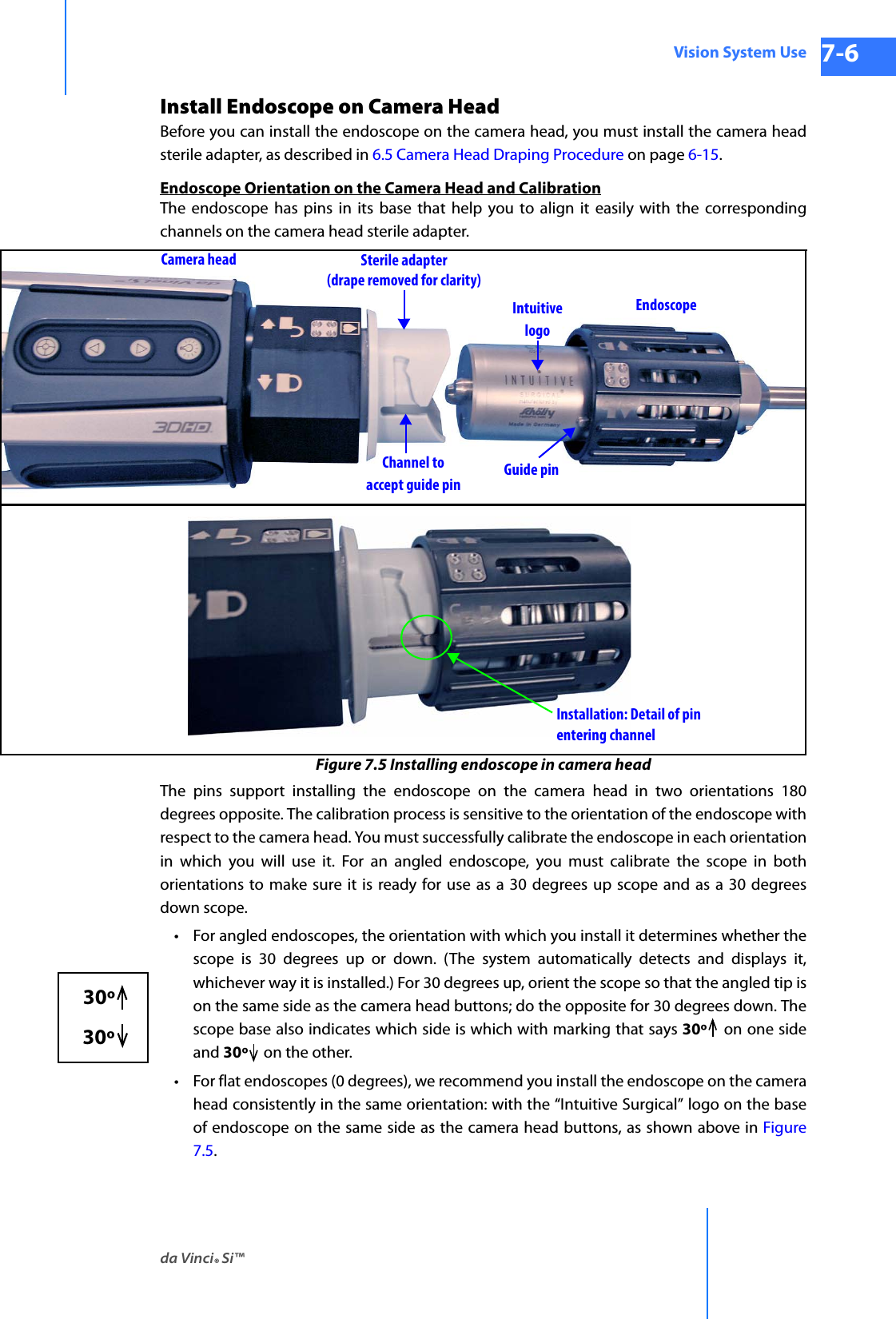
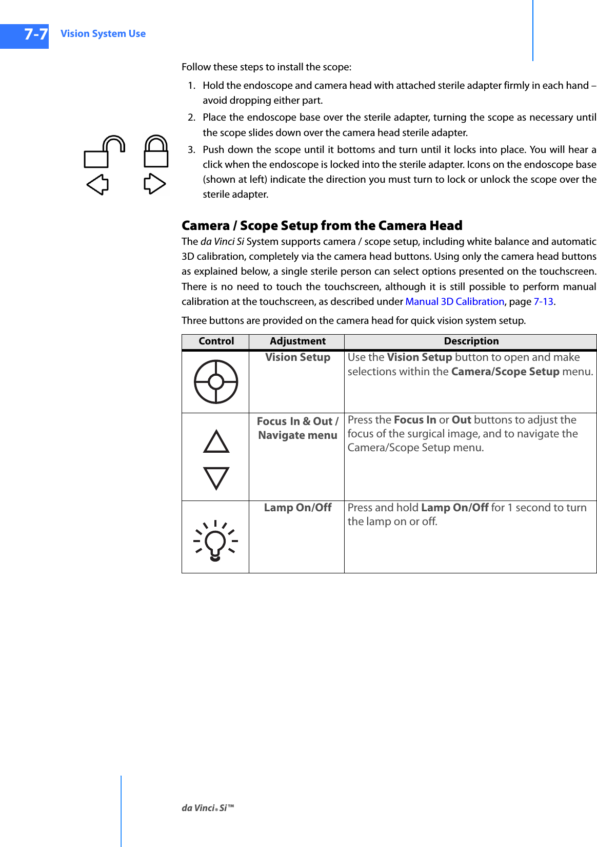
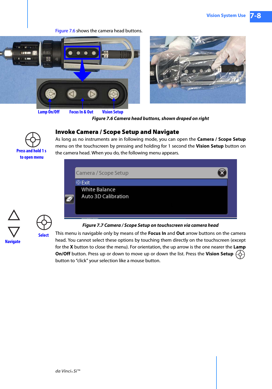
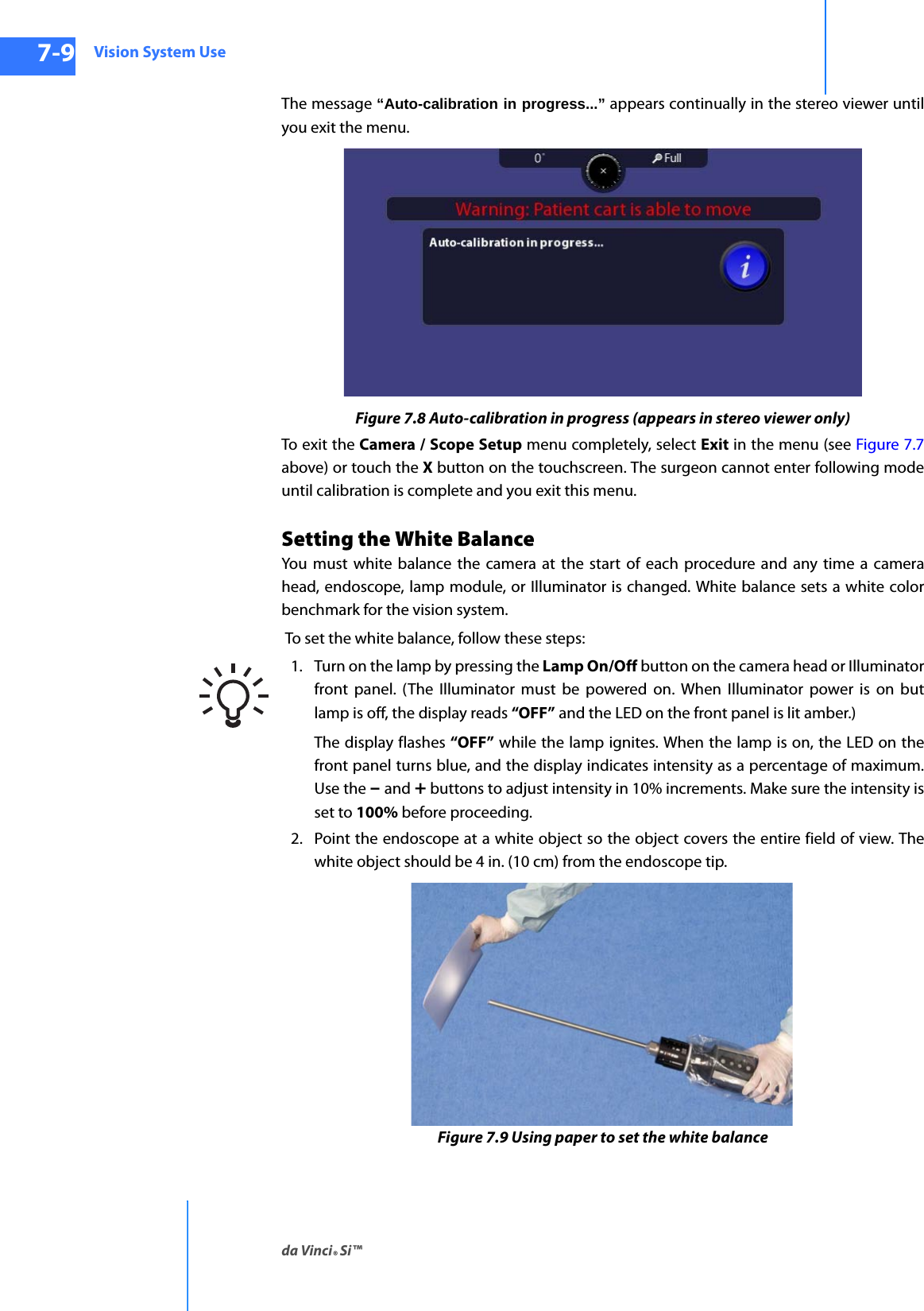
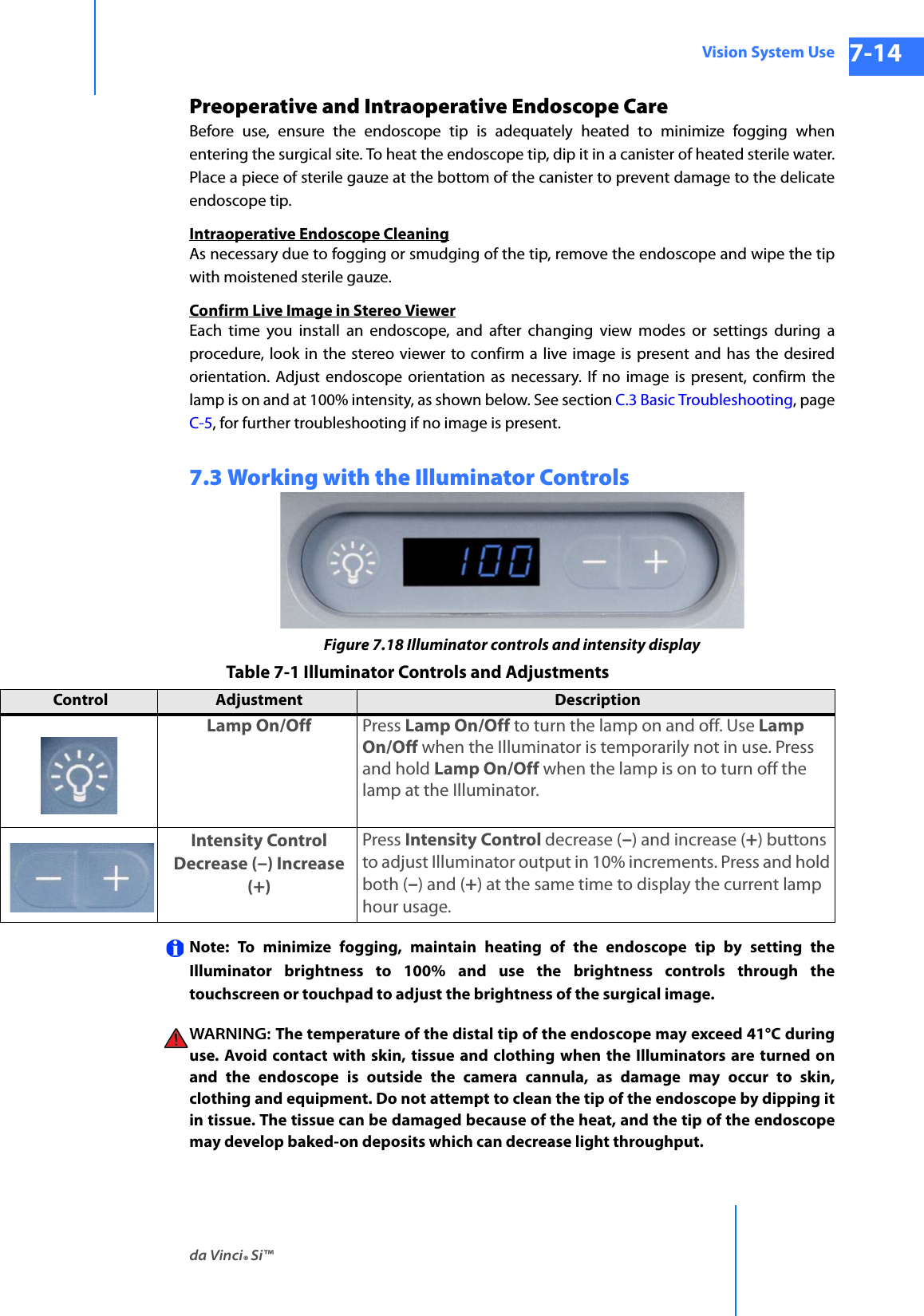
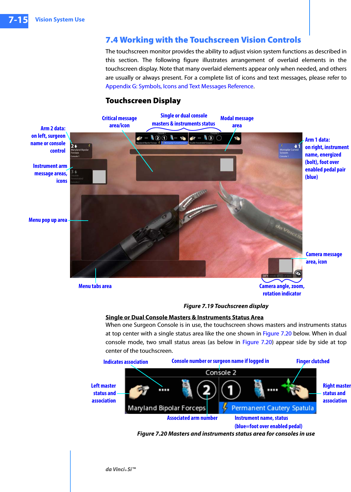
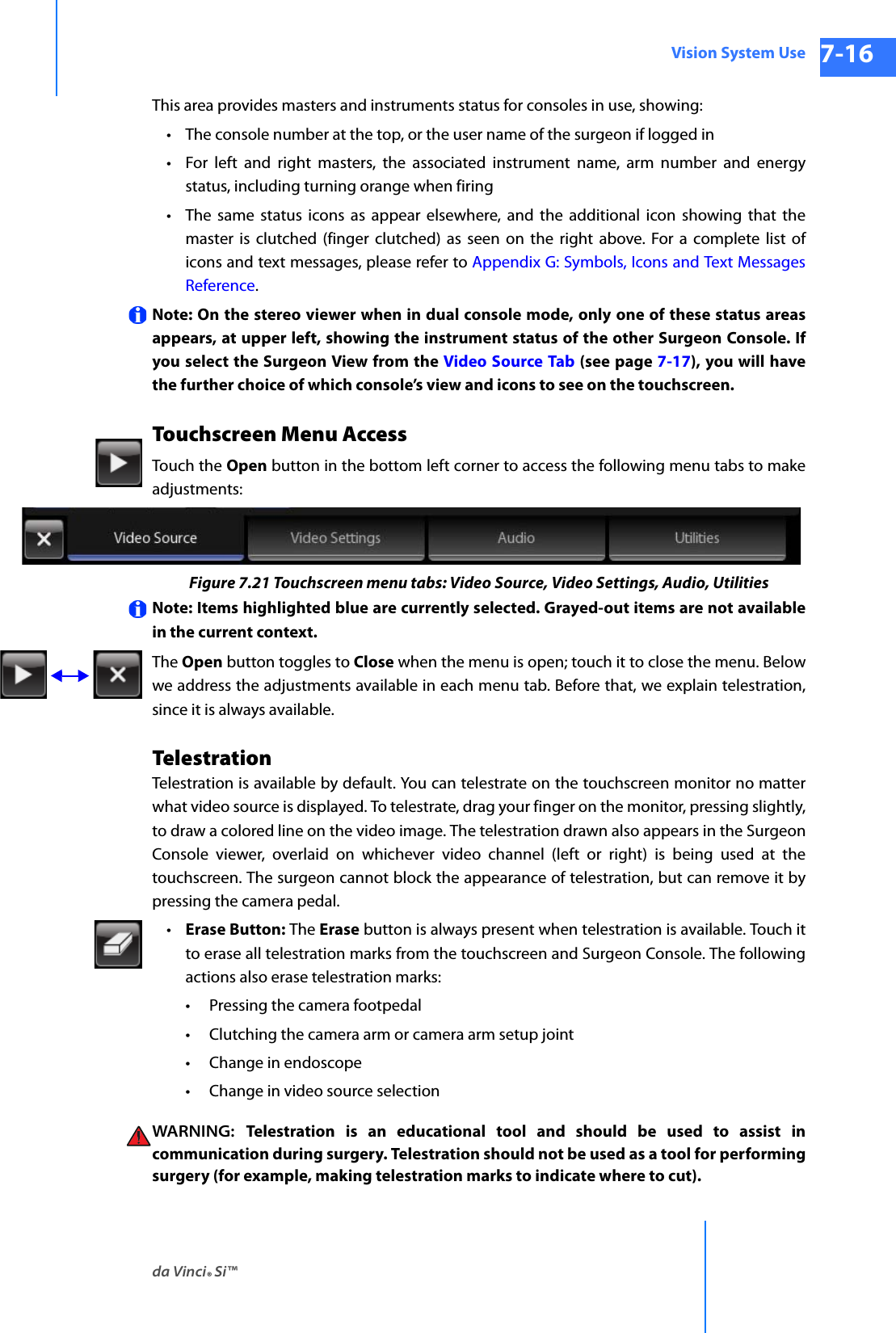
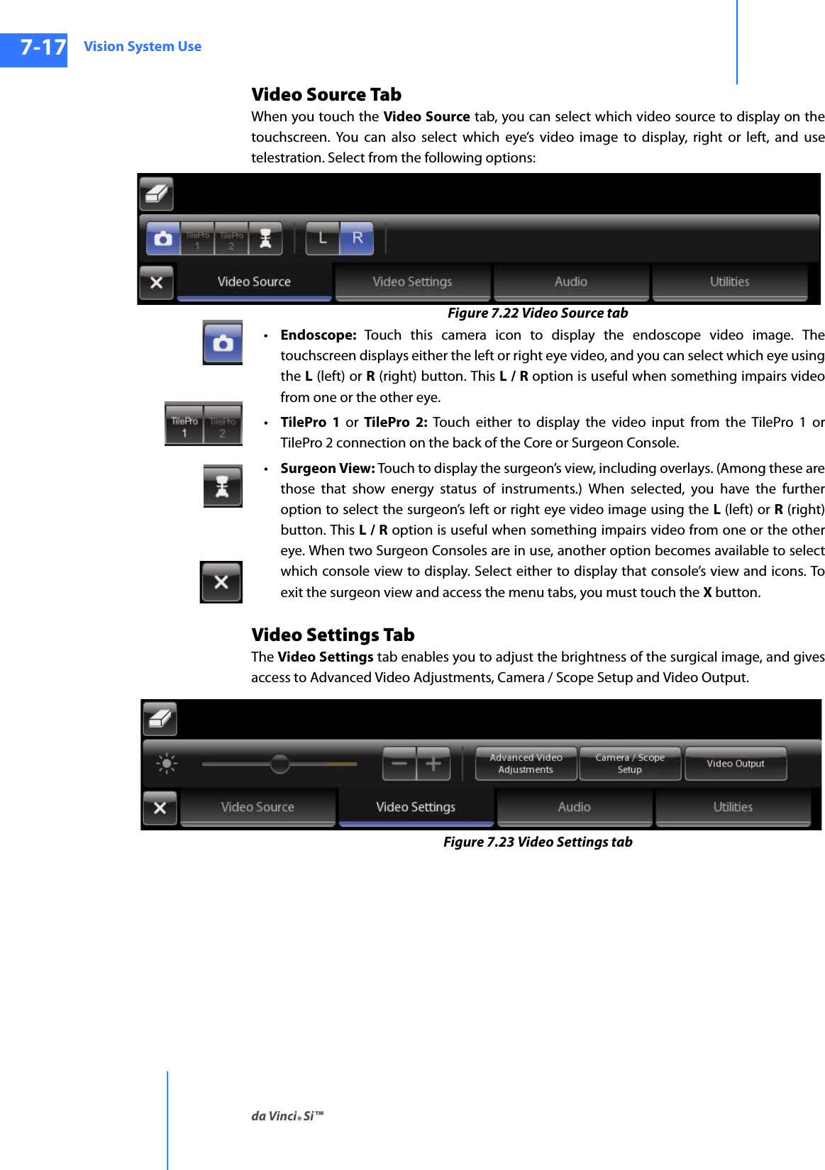
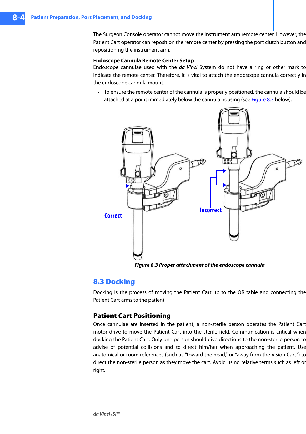
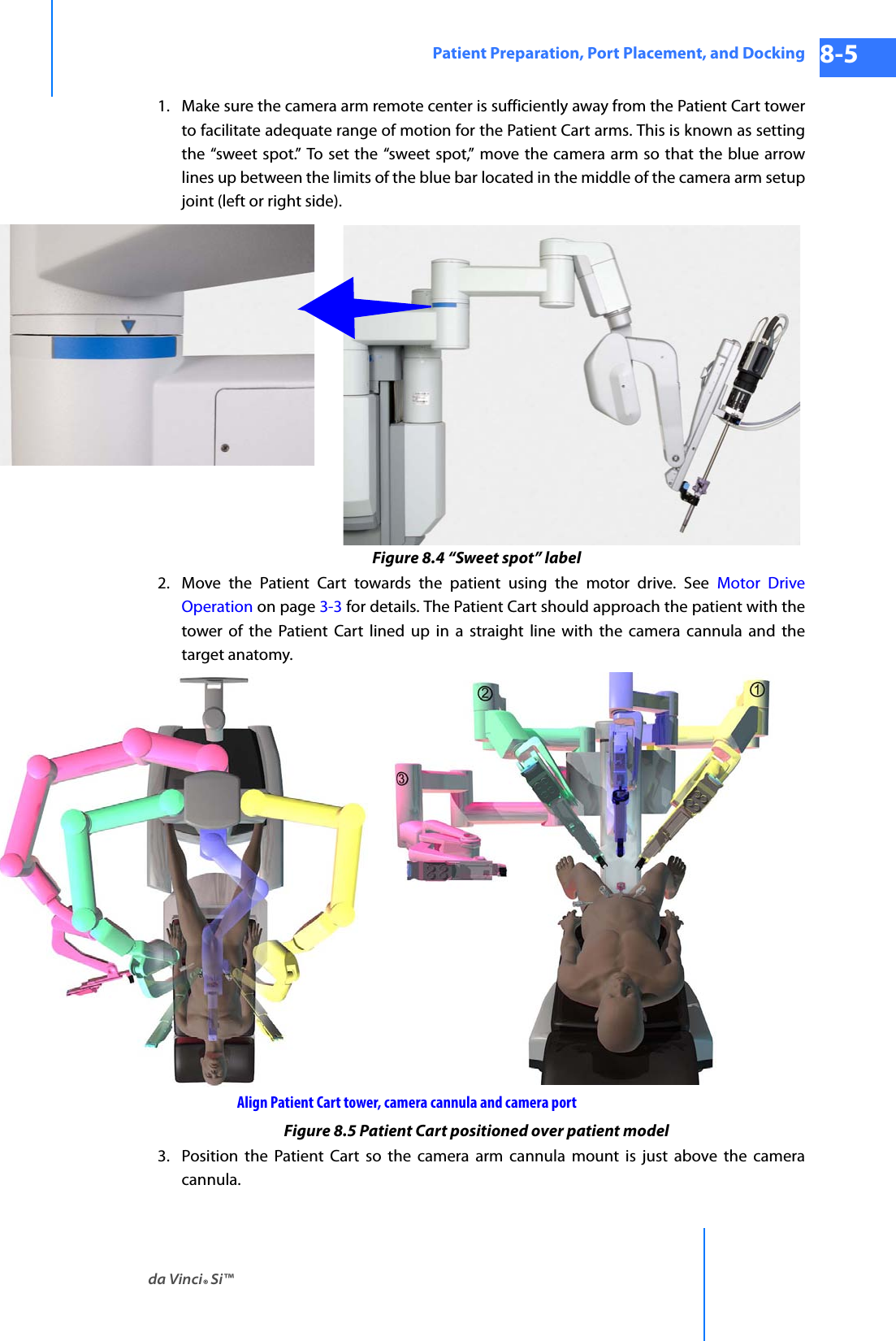
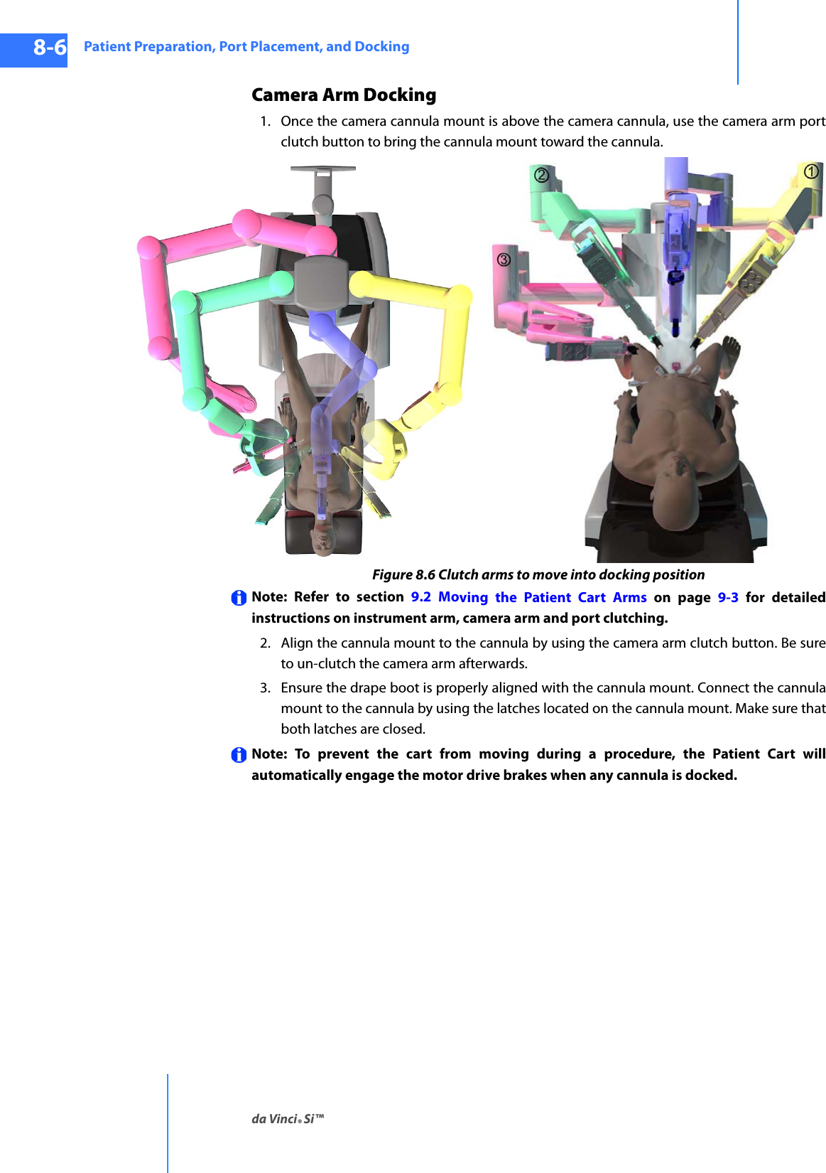
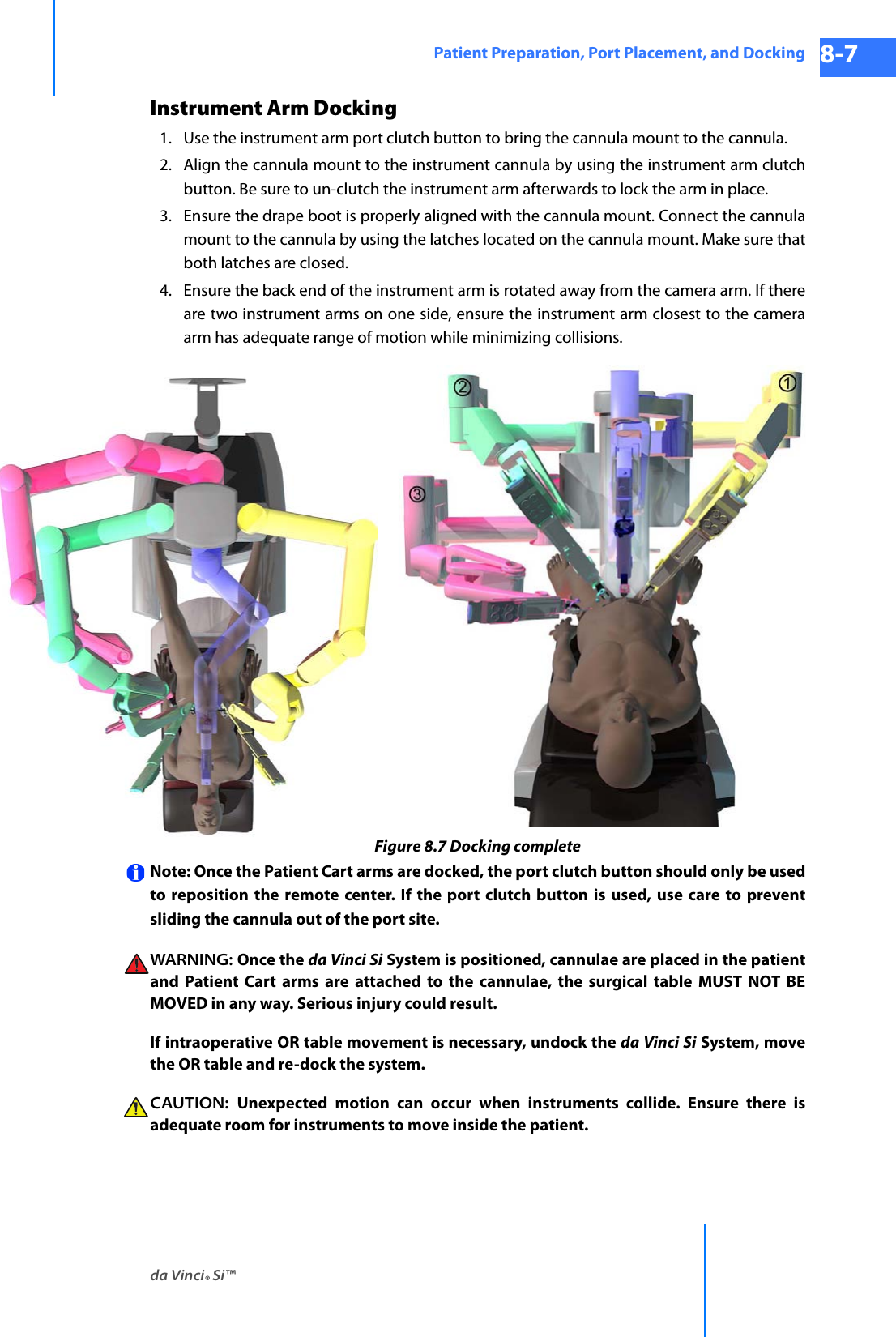
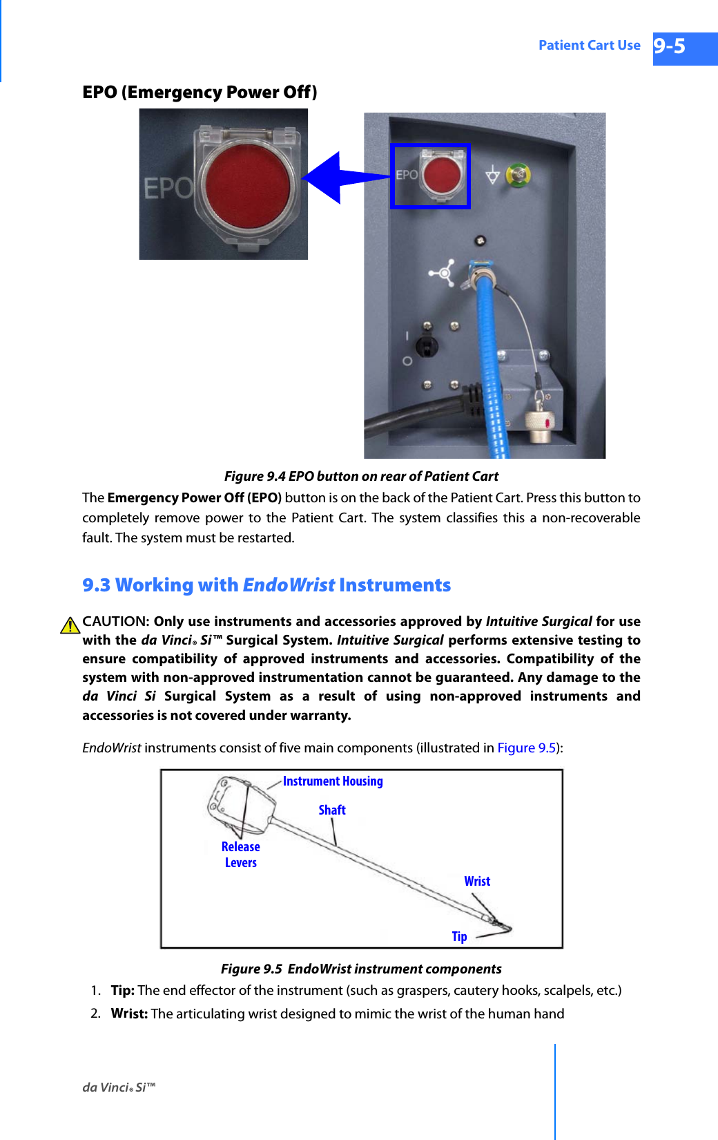
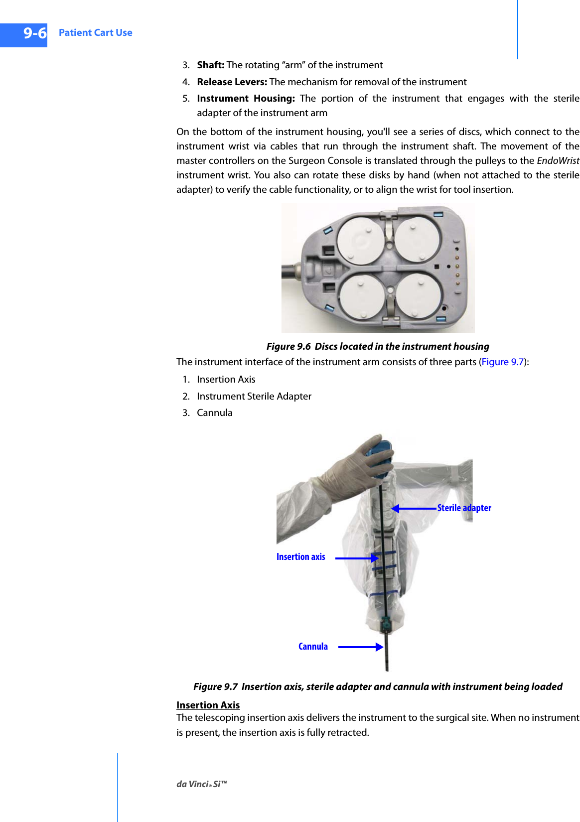
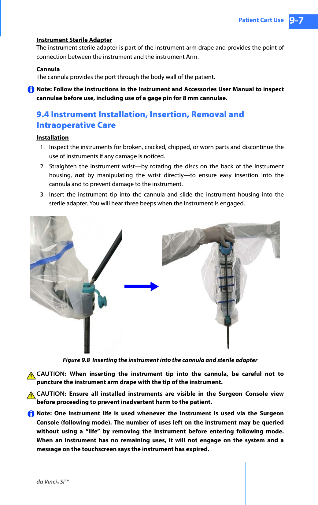
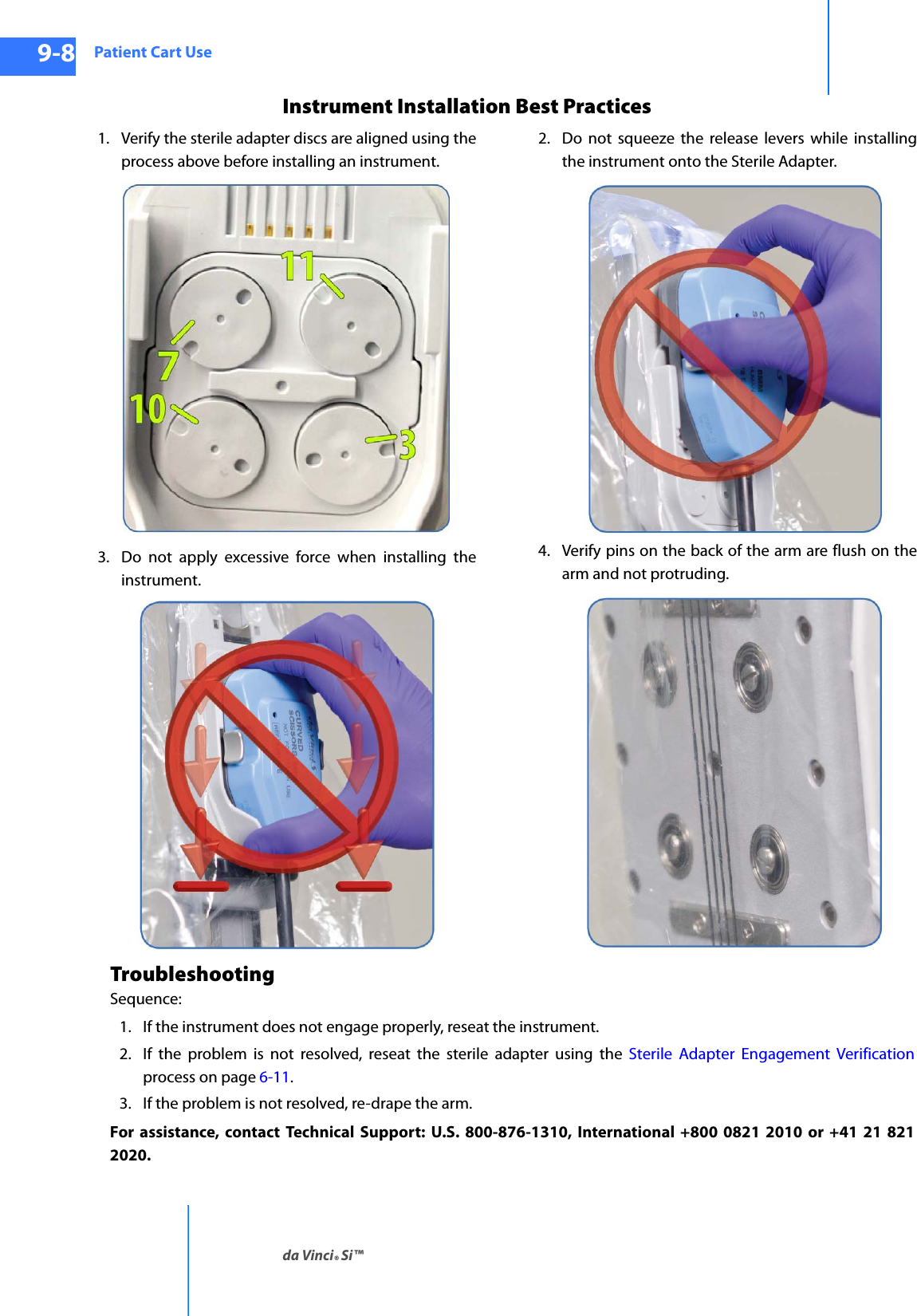
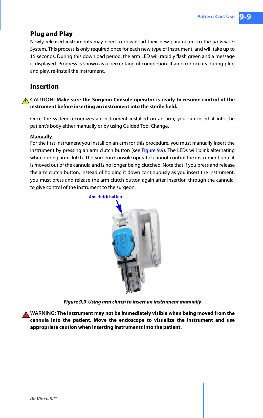
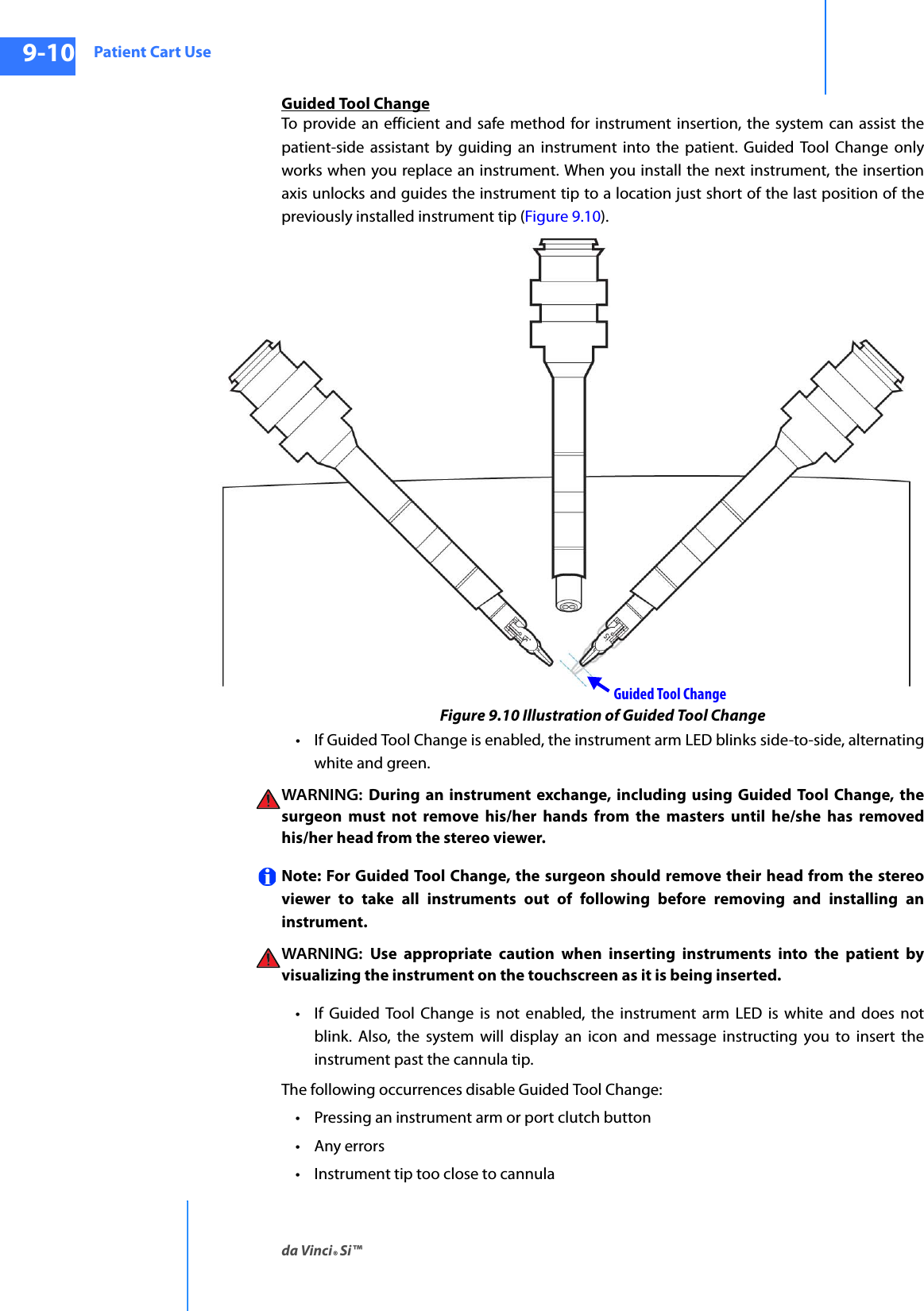
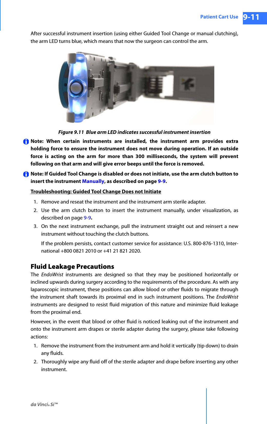
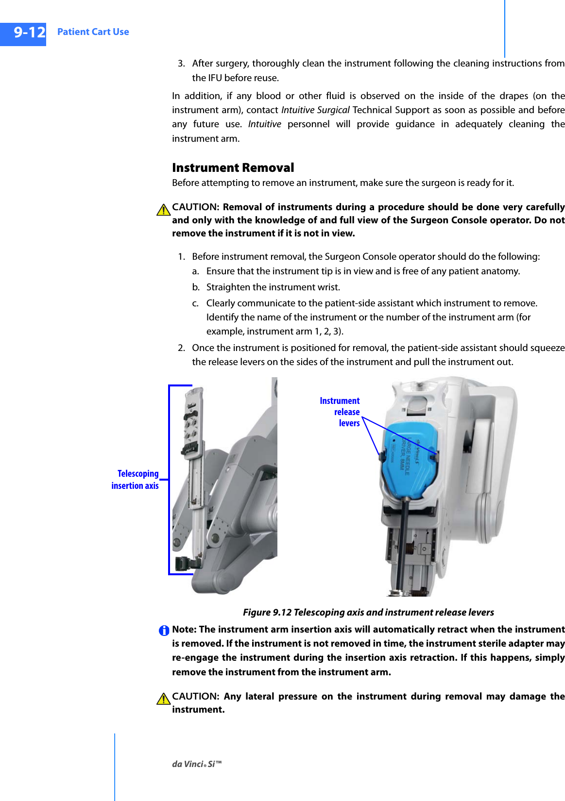
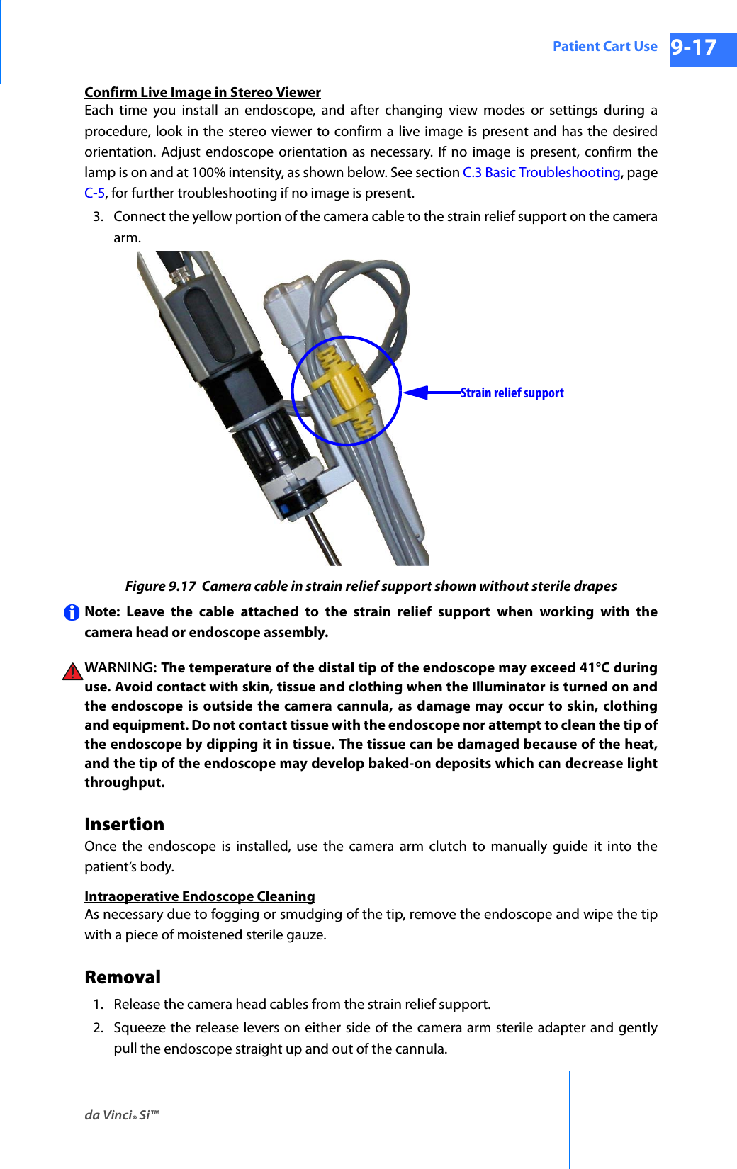
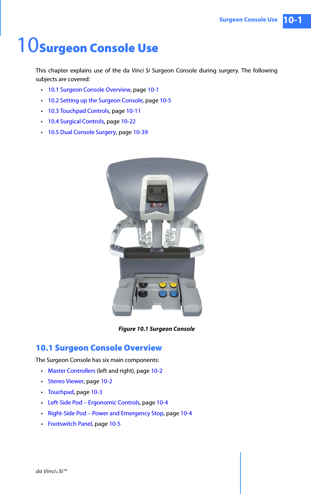
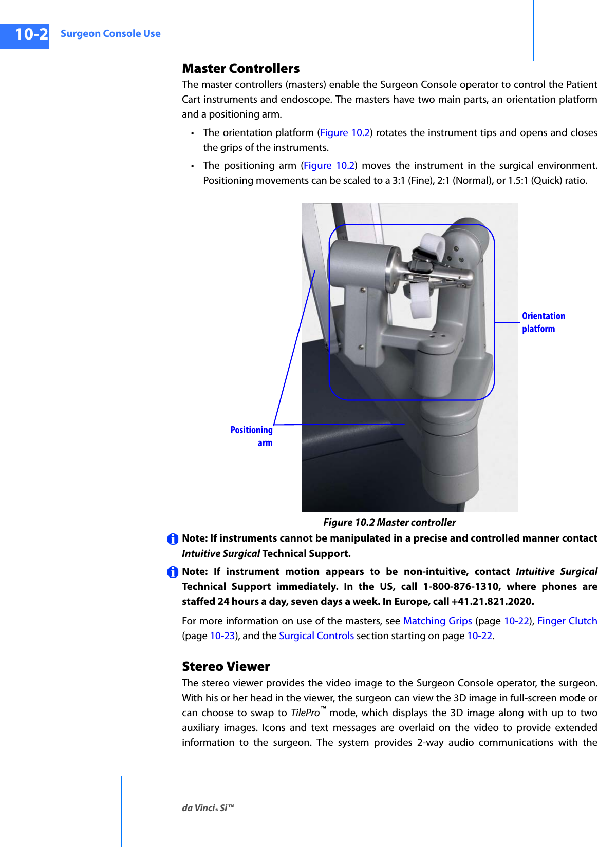
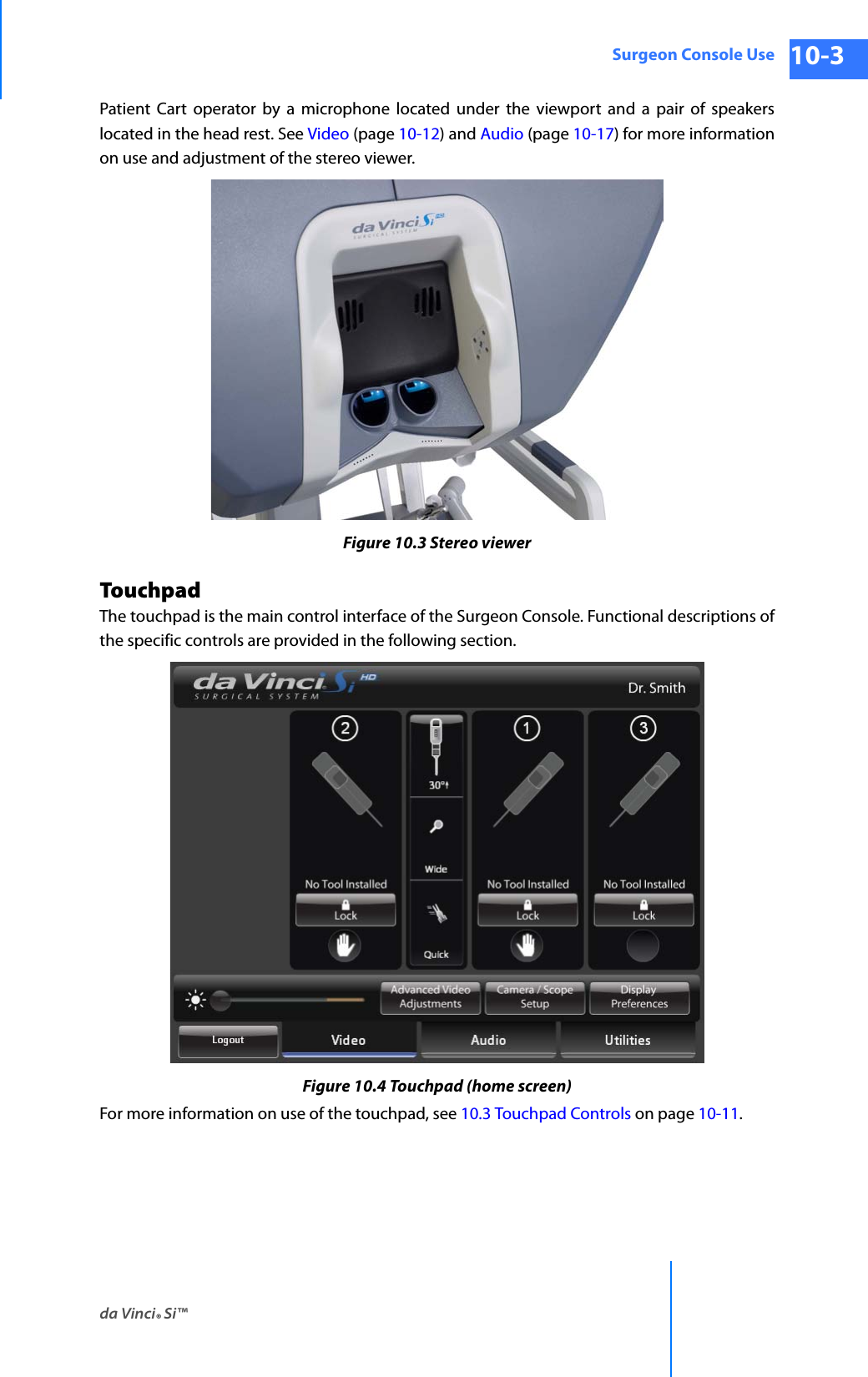
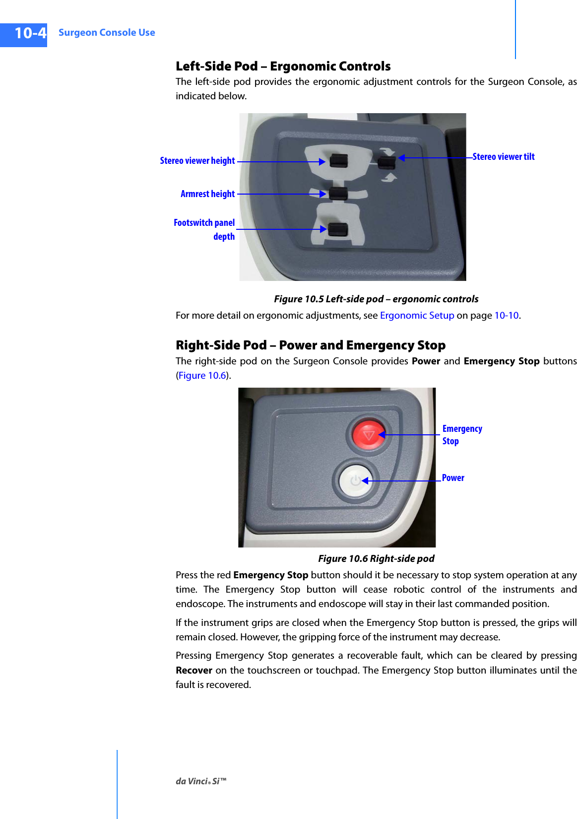
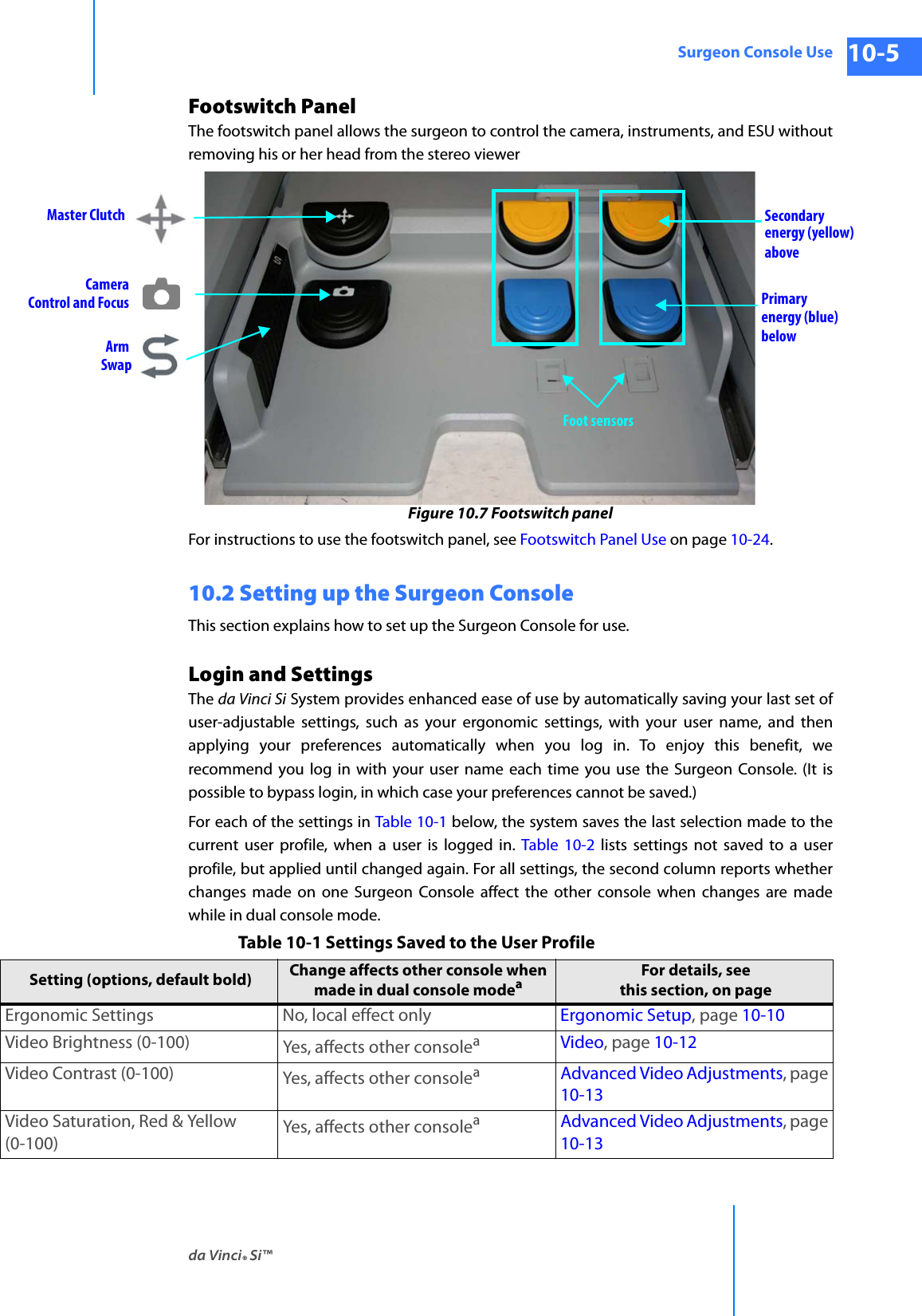
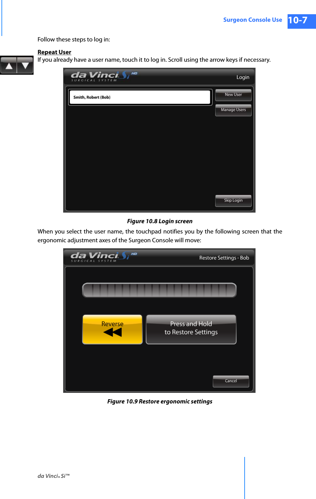
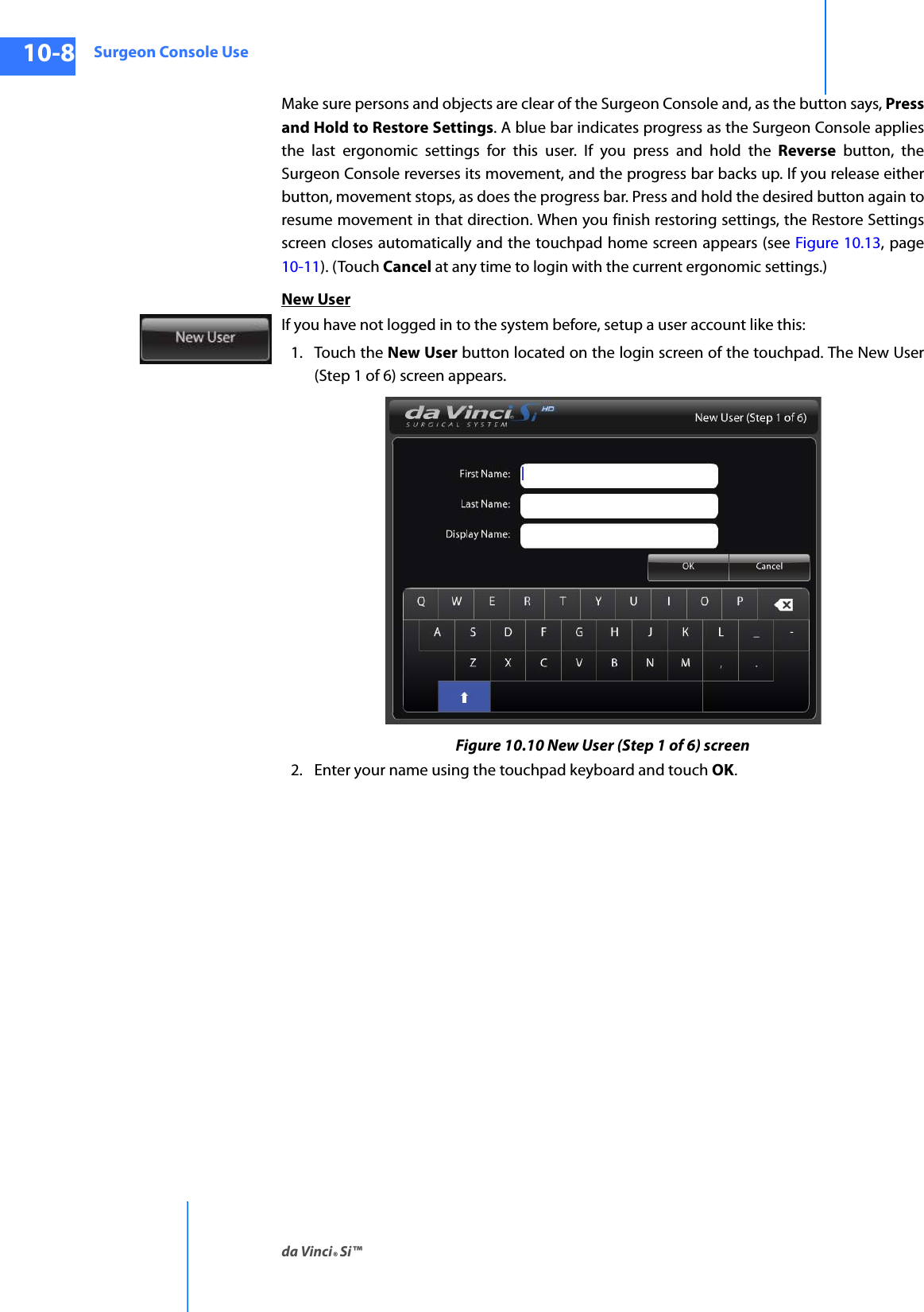
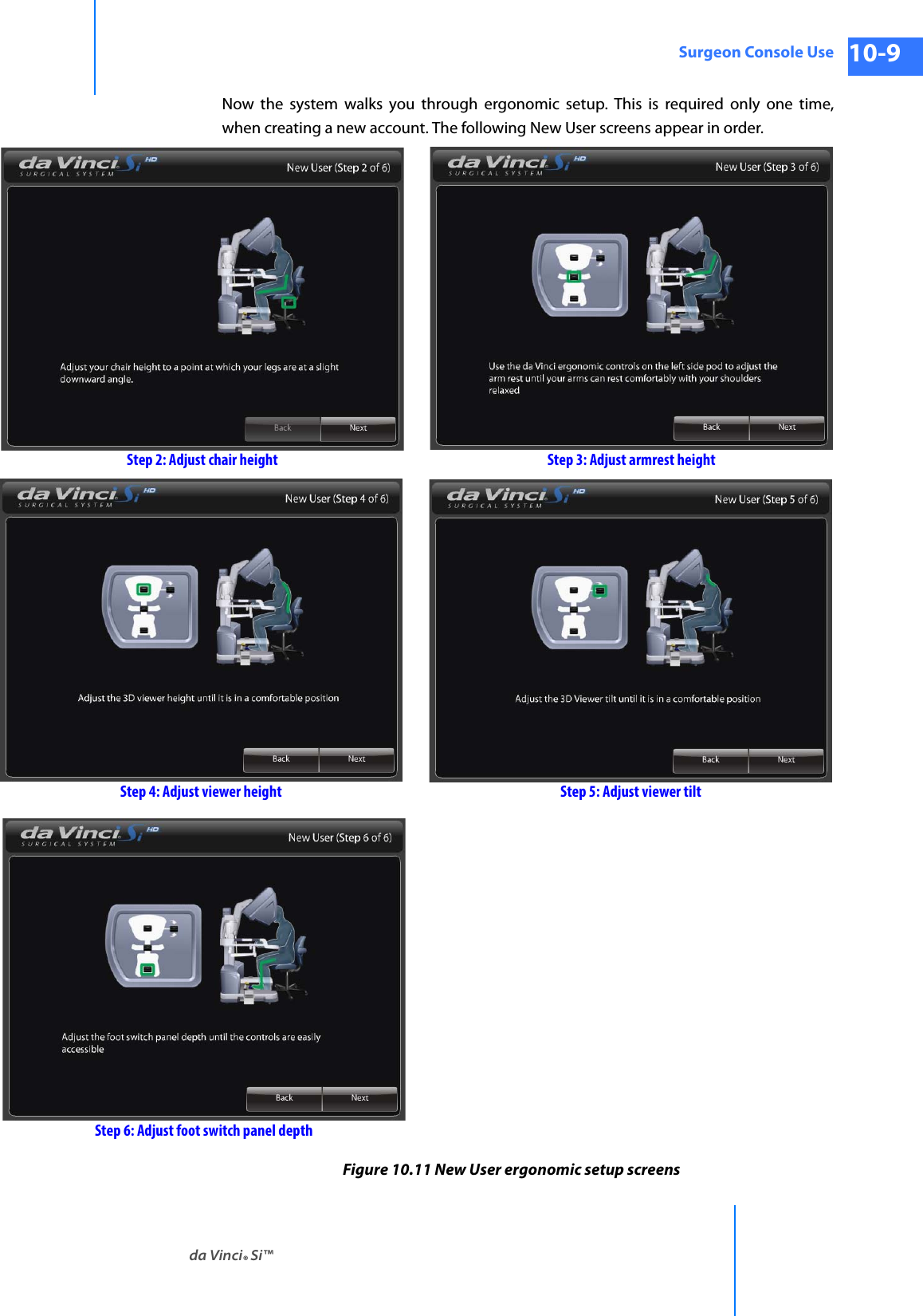
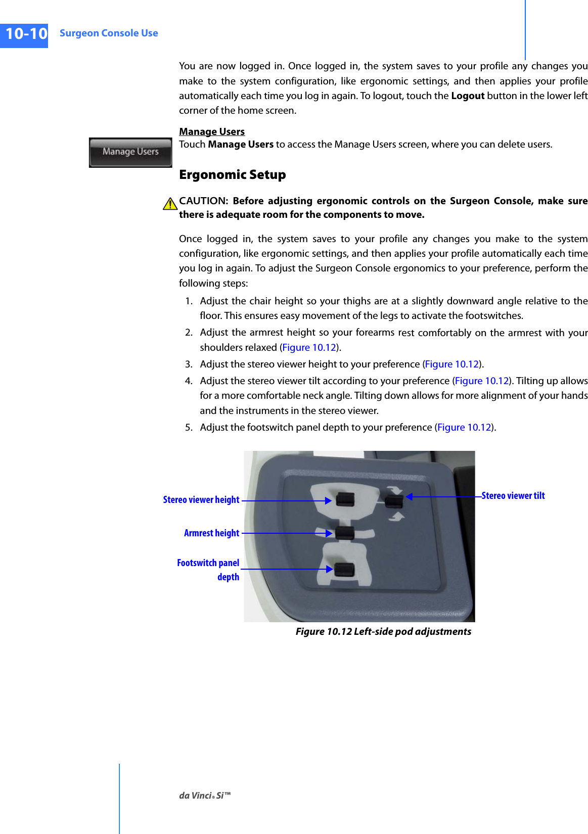
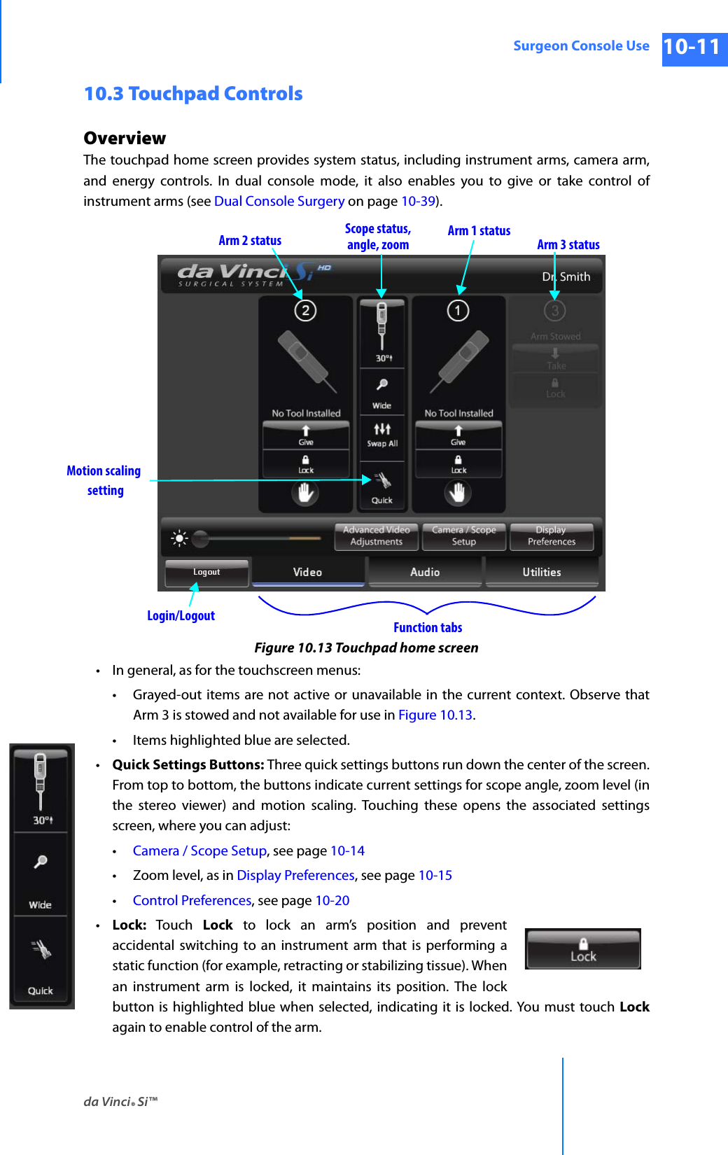
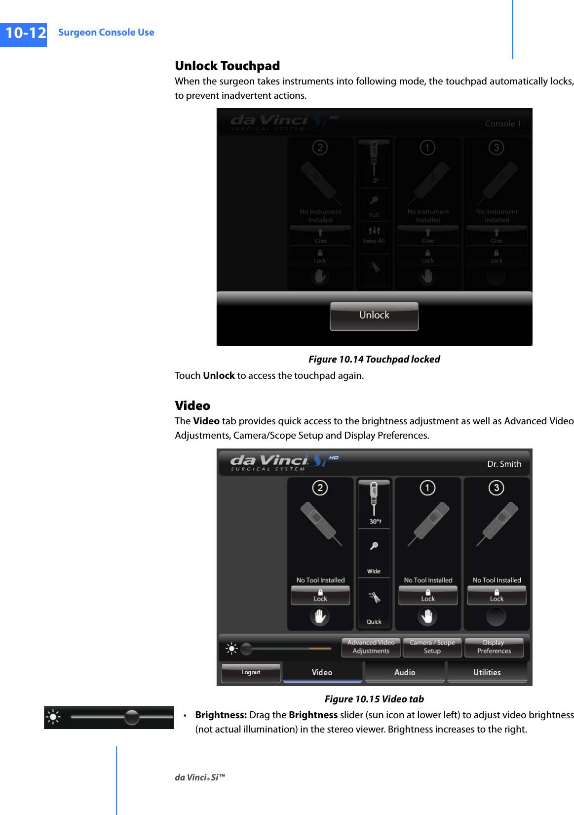
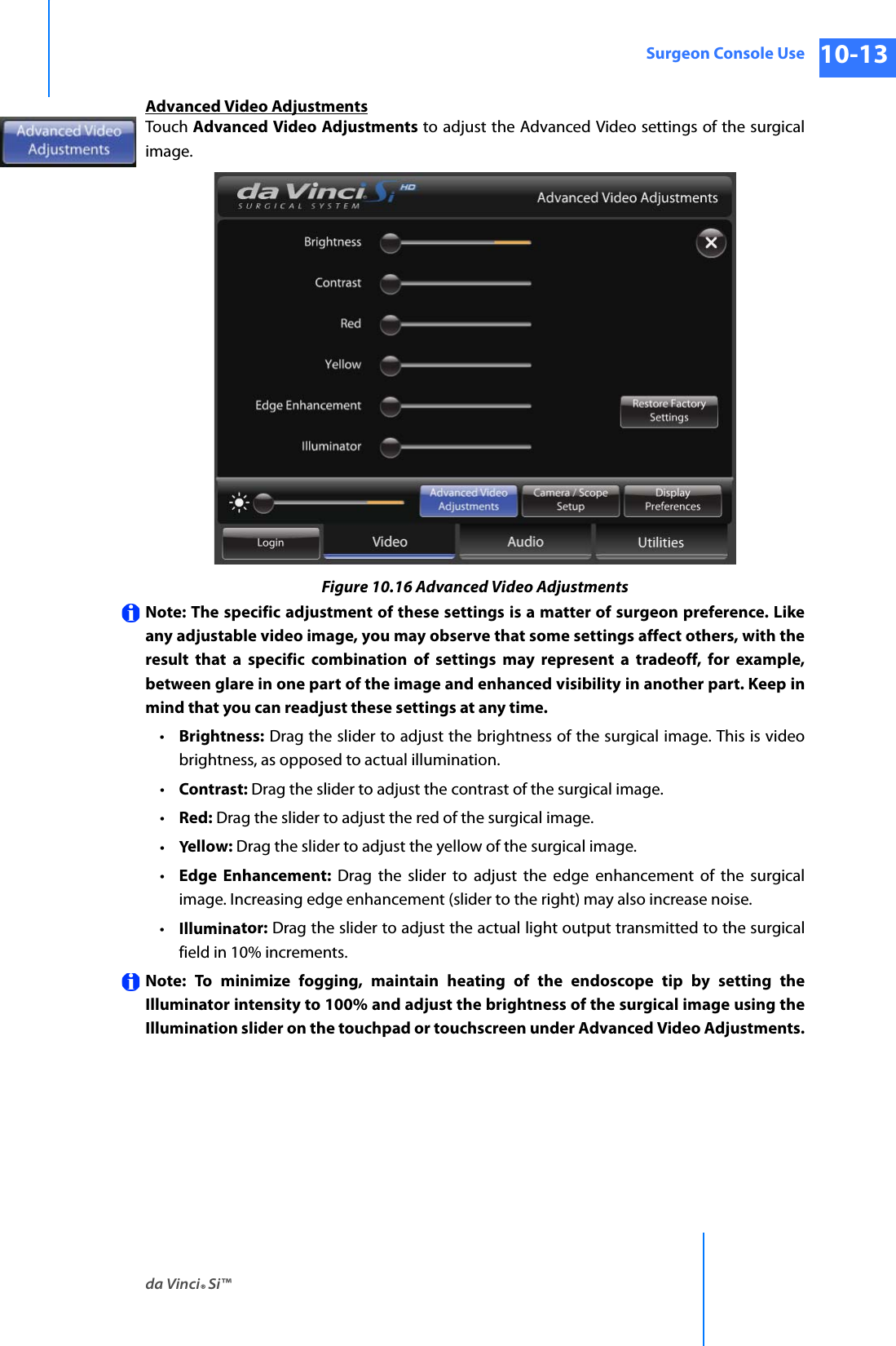
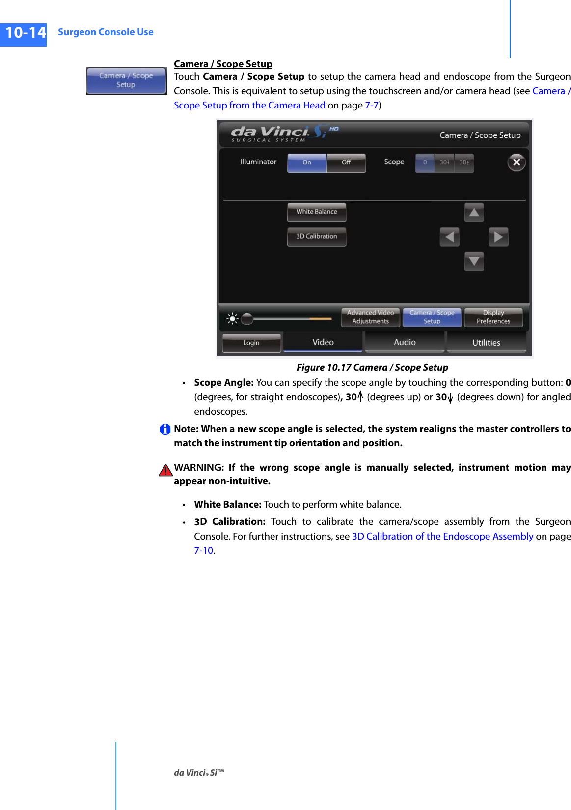
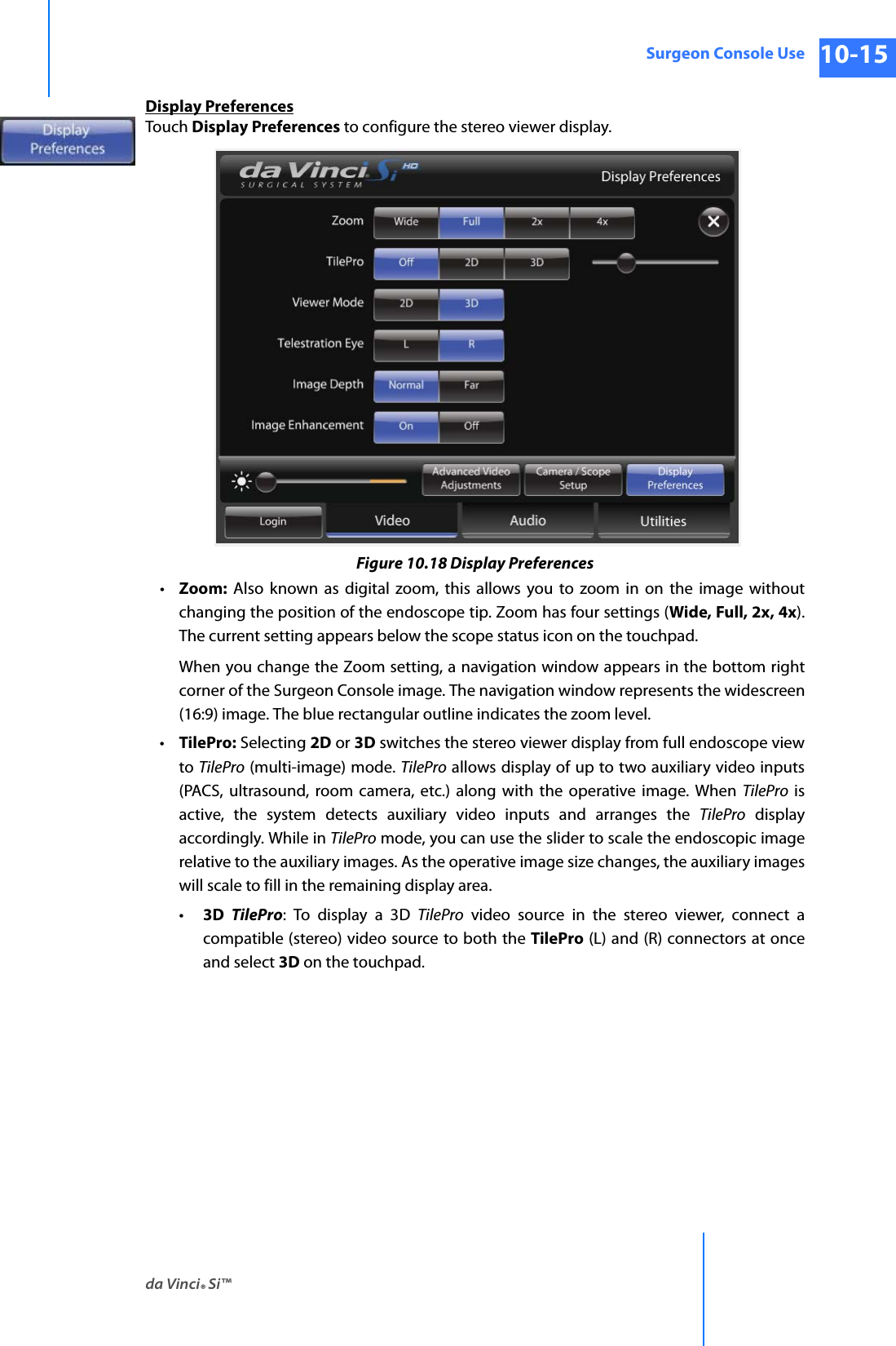
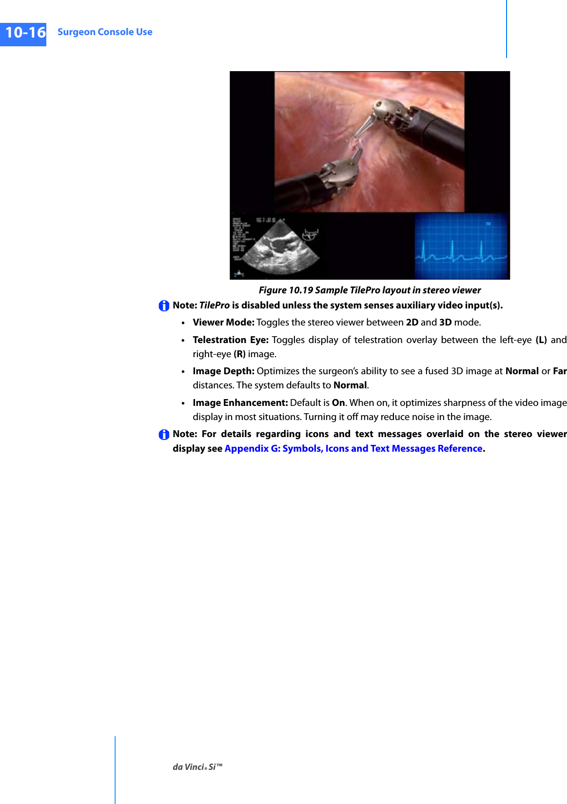
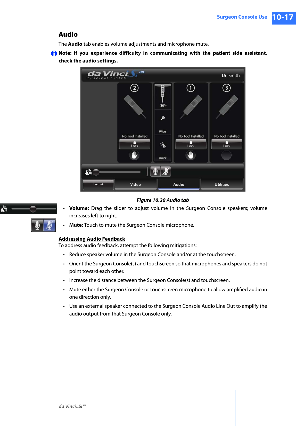
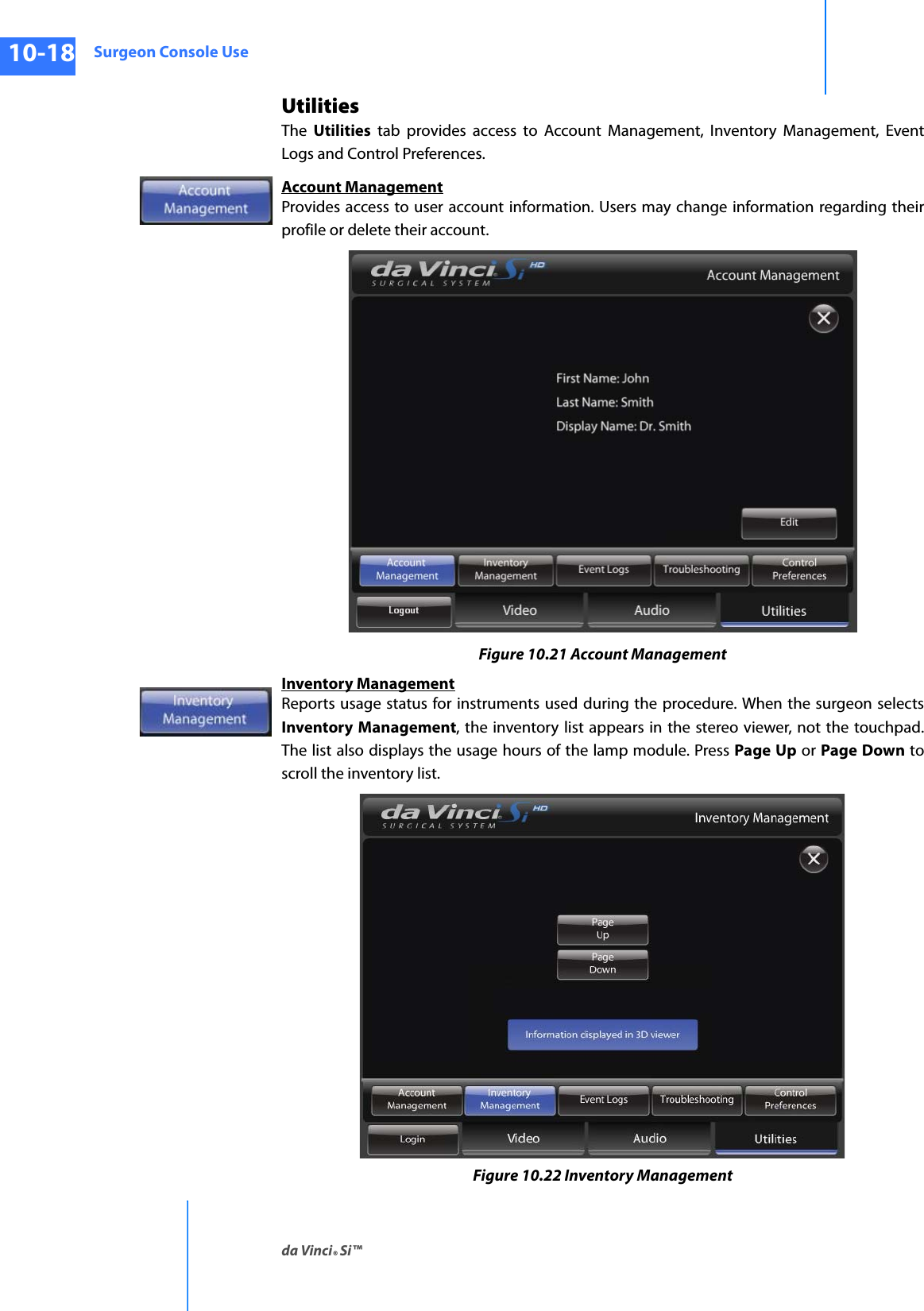
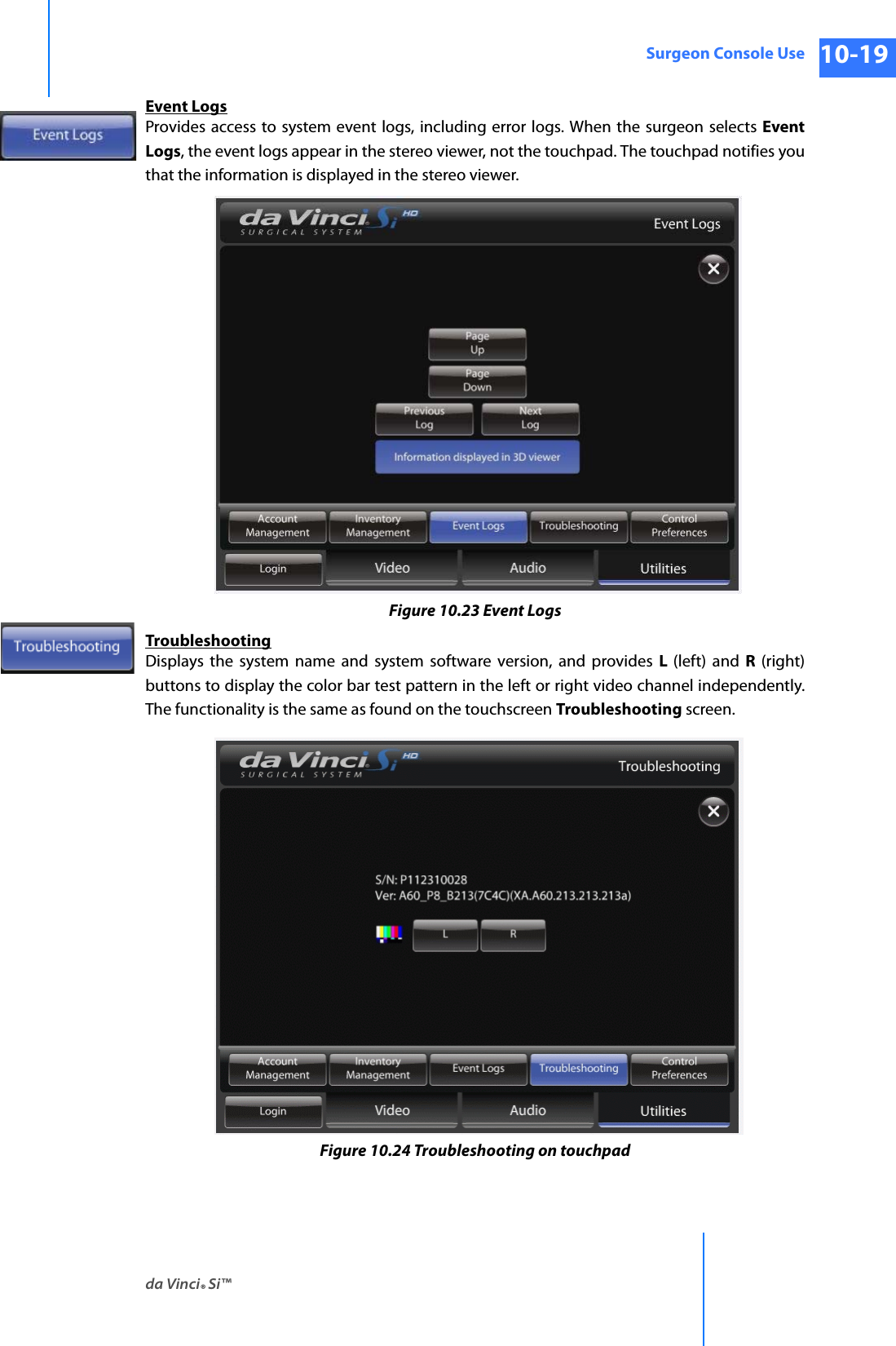
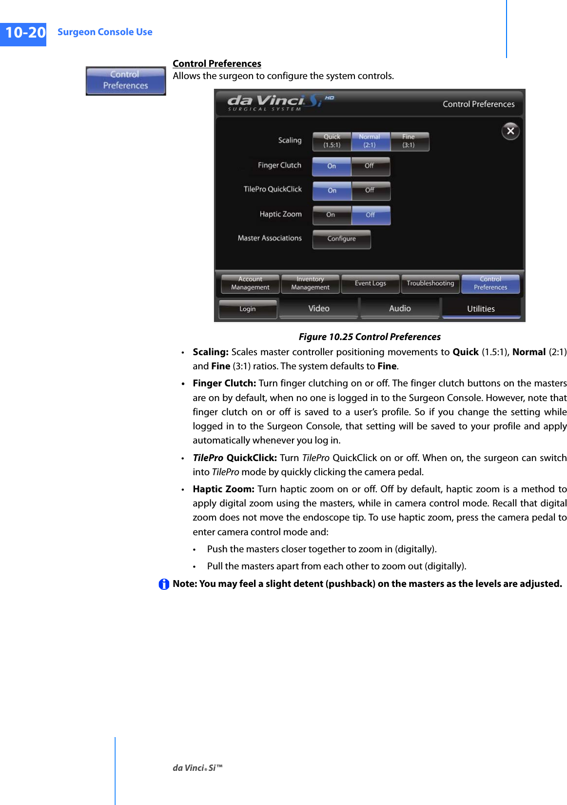
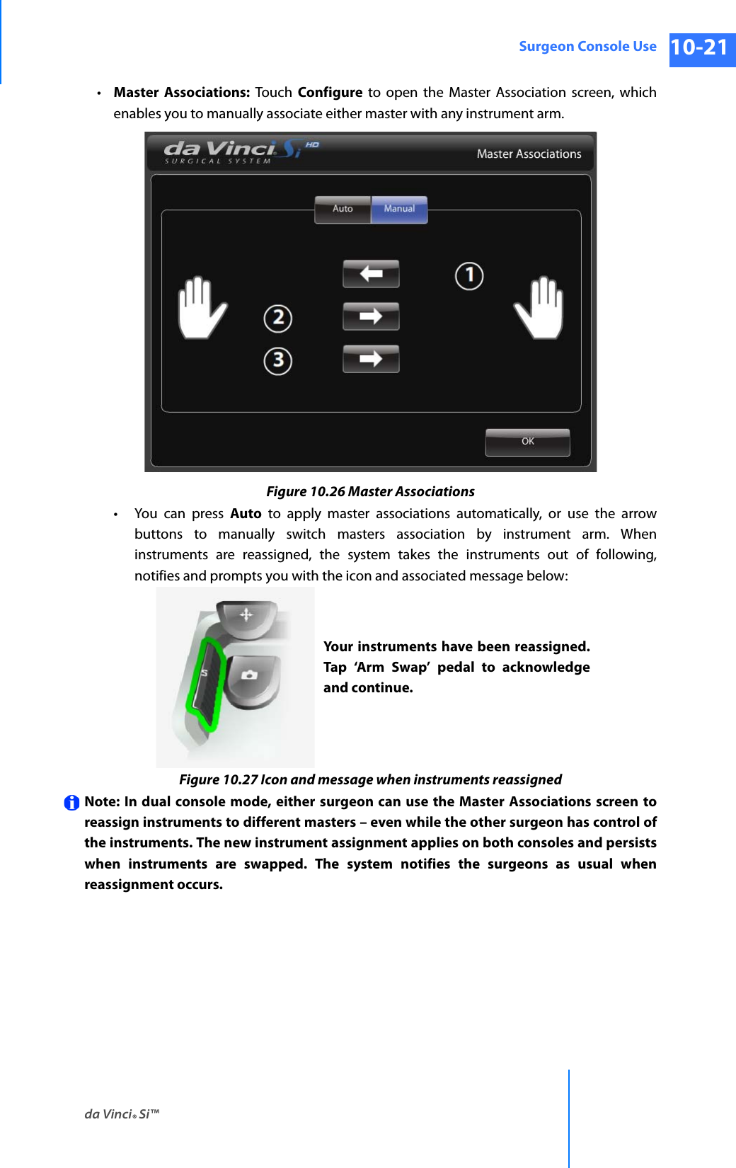
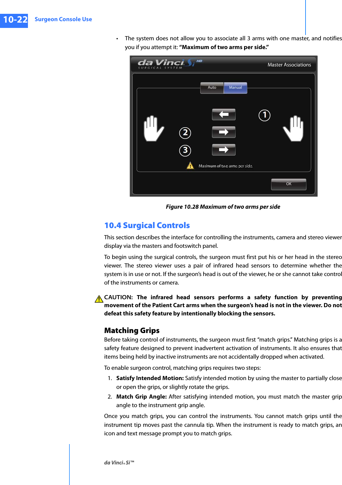
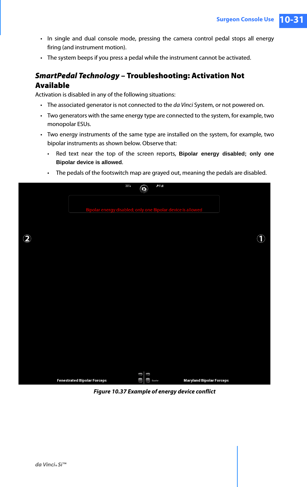
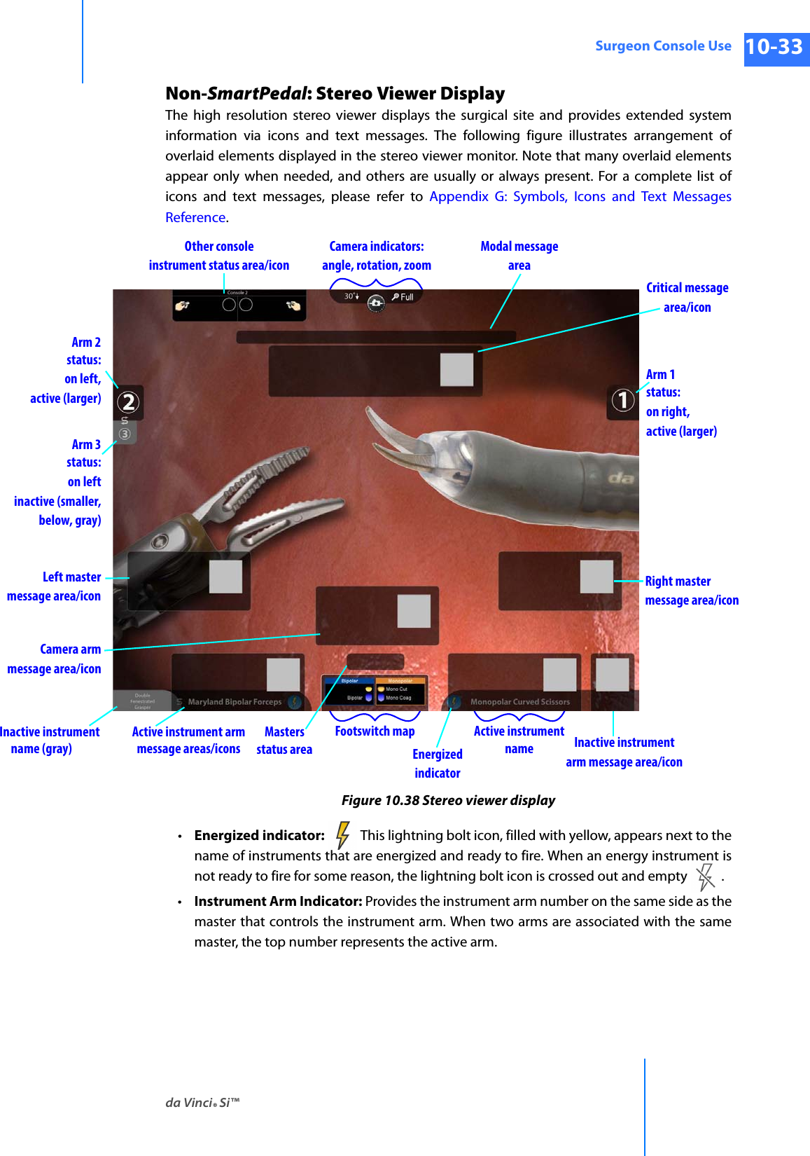
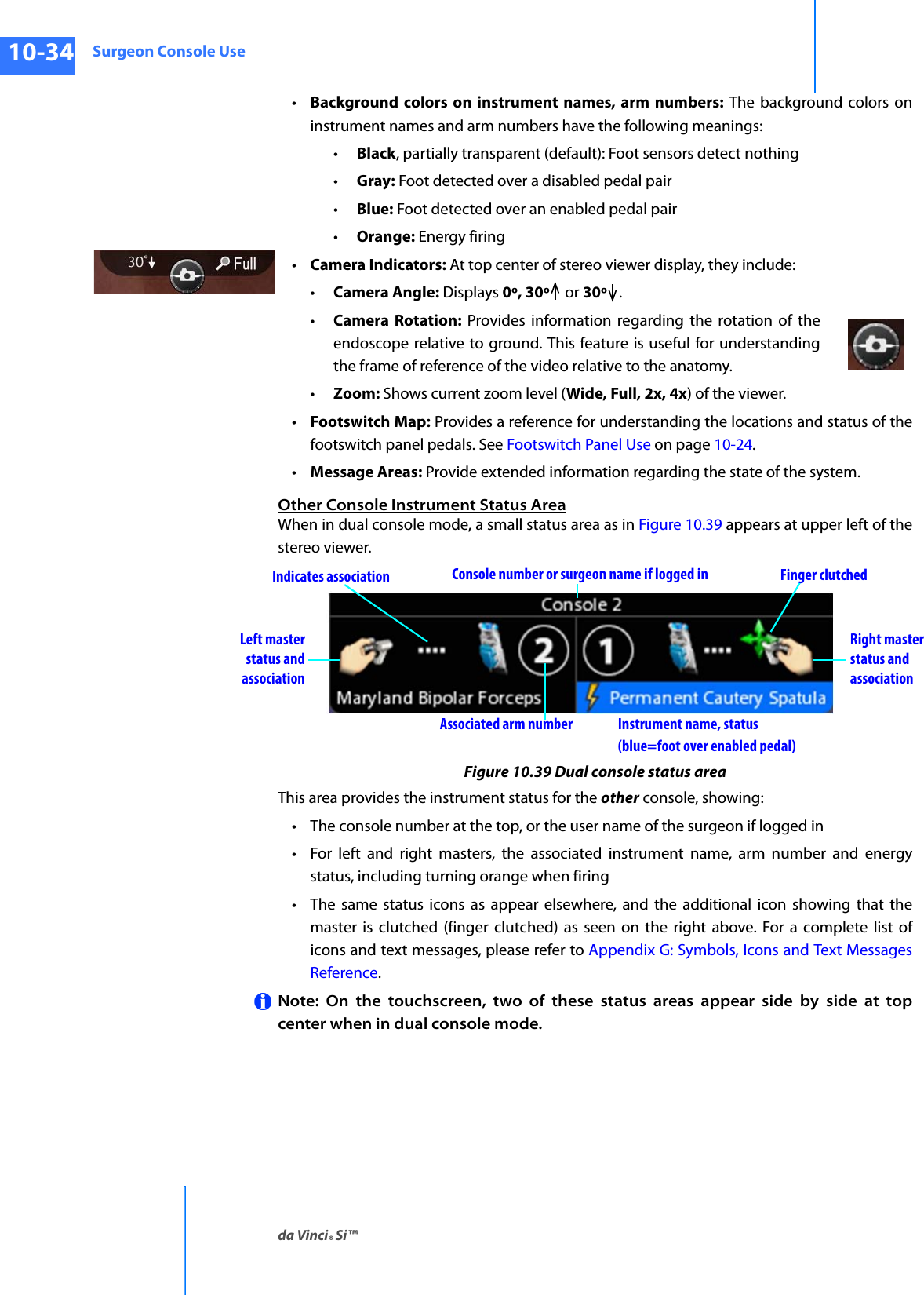
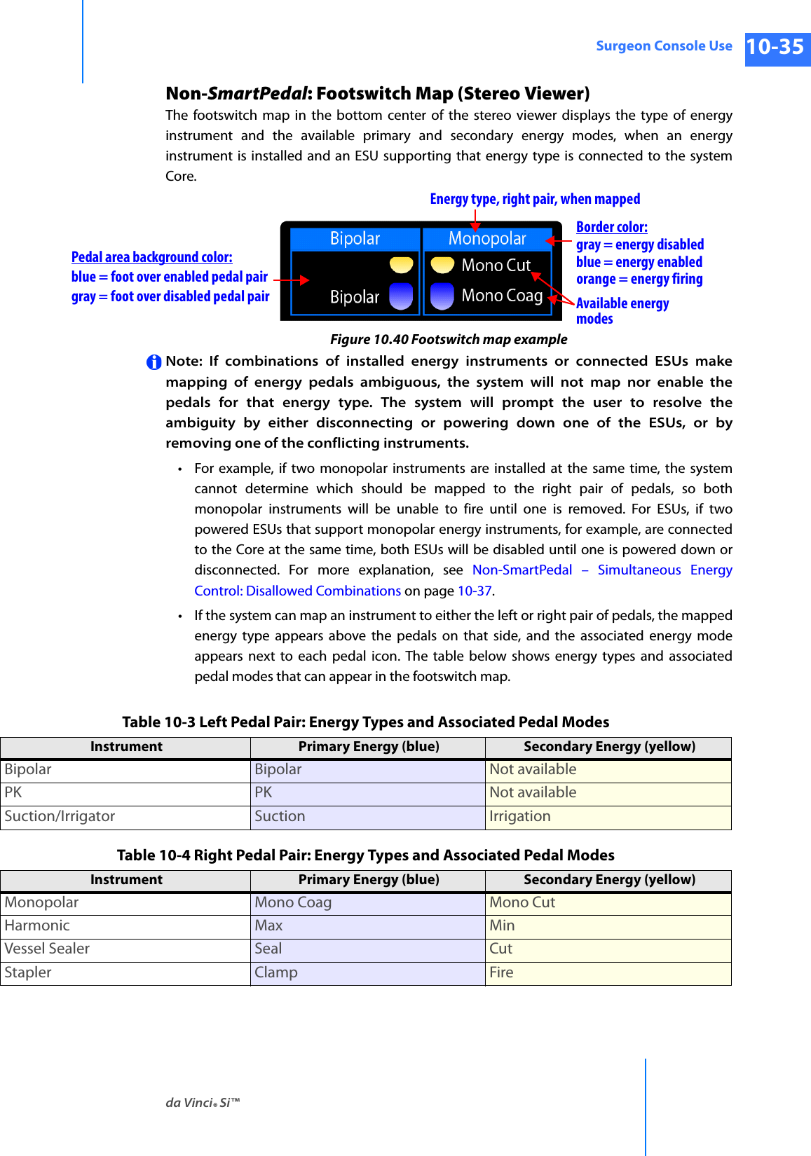
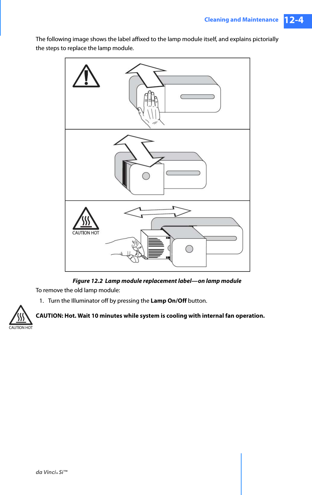
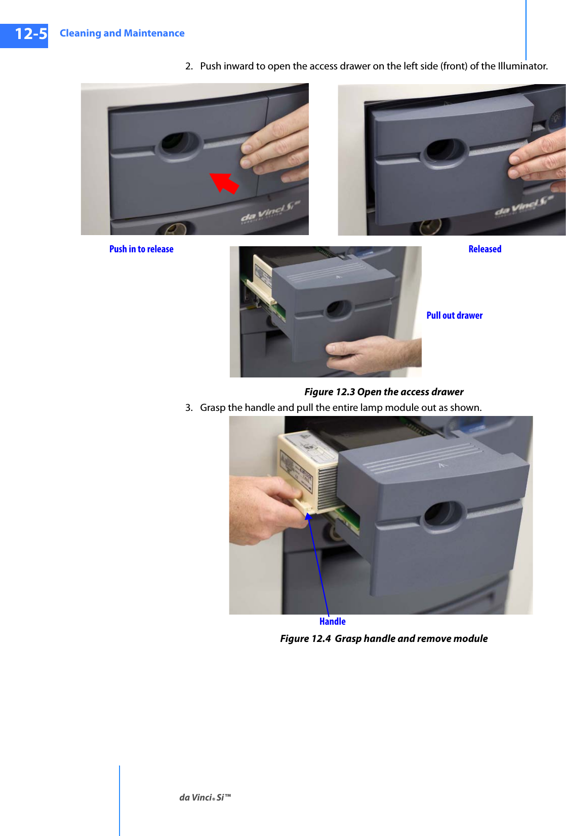
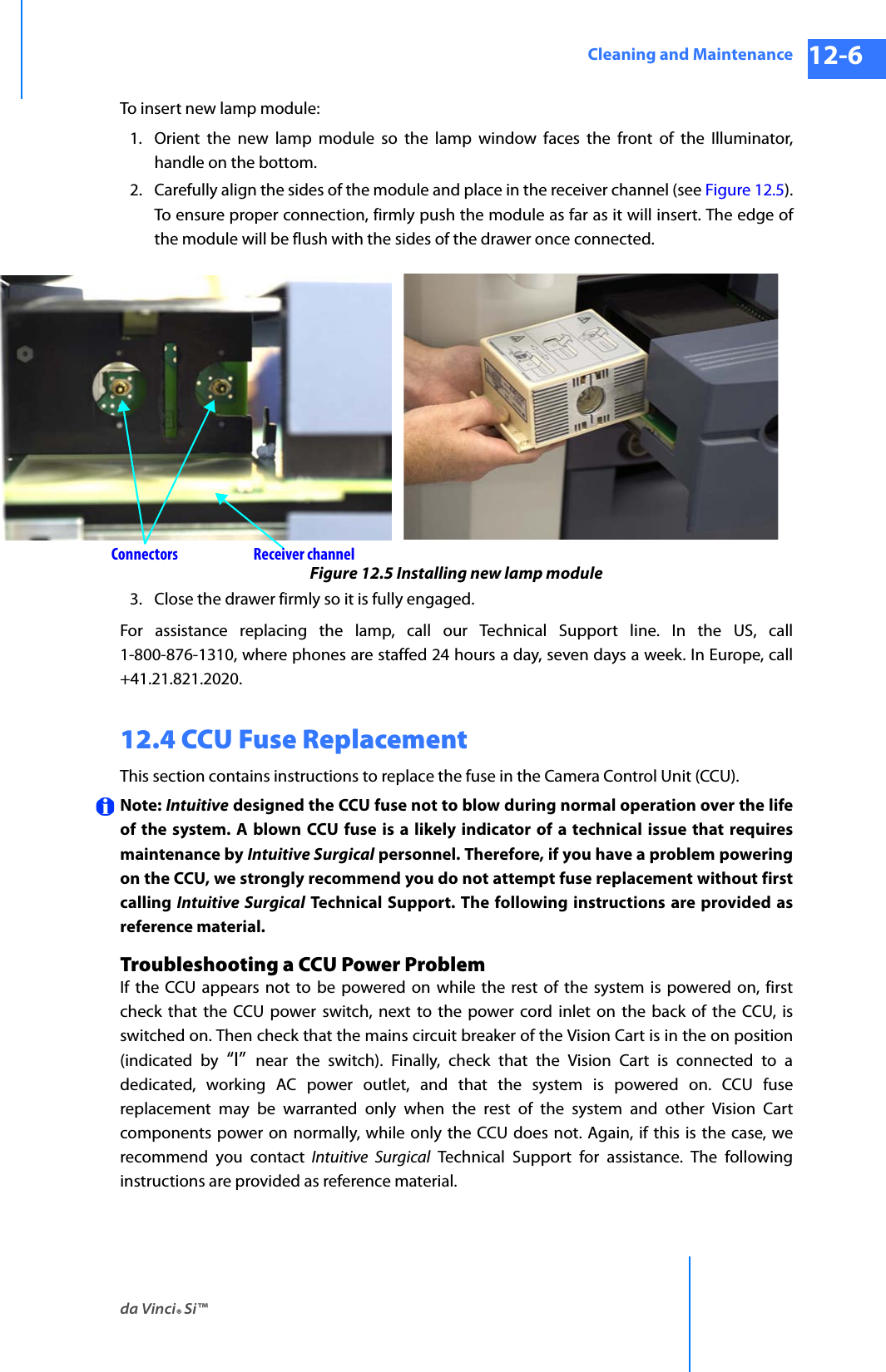
User Manual Part 2