Invengo Information Technology XC-RF850 Reader User Manual
Invengo Information Technology Co., Ltd. Reader Users Manual
UserManual.wiki
>
Invengo Information Technology
>
XC RF850 User Manual
Users Manual
Navigation menu
Upload a User Manual
Namespaces
Wiki Guide
HTML
PDF
Info
Views
User Manual
Discussion / Help
Navigation
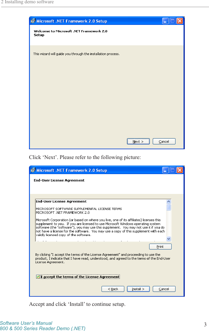
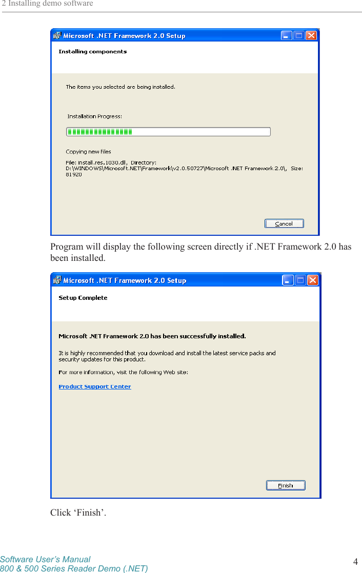
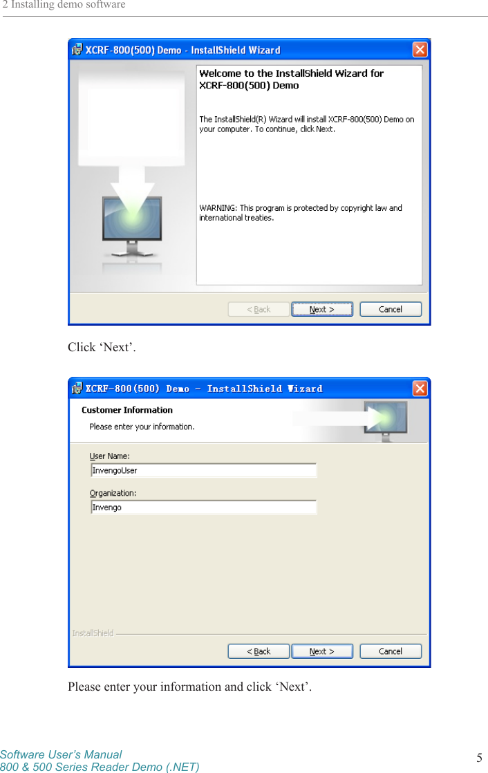
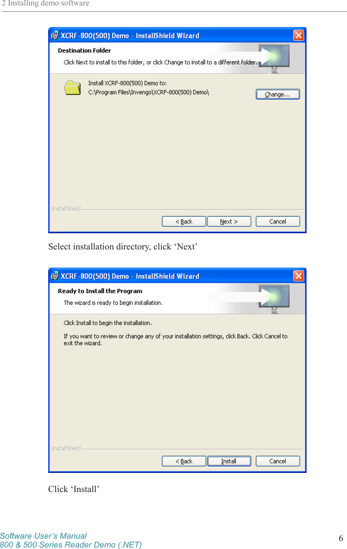
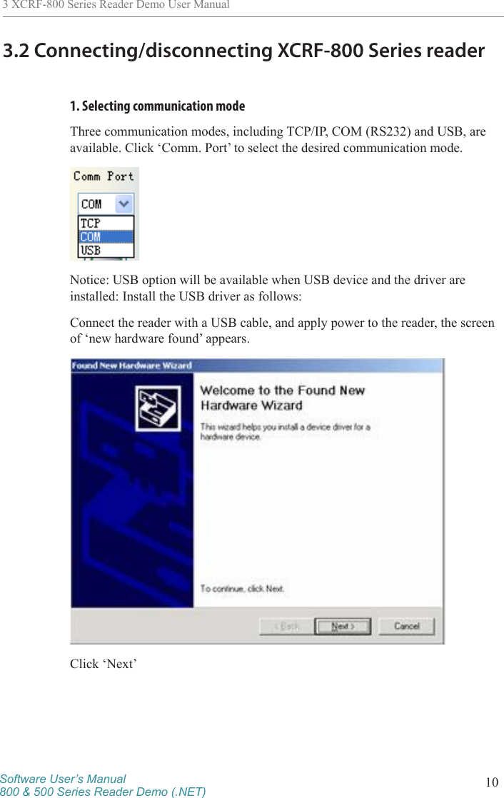
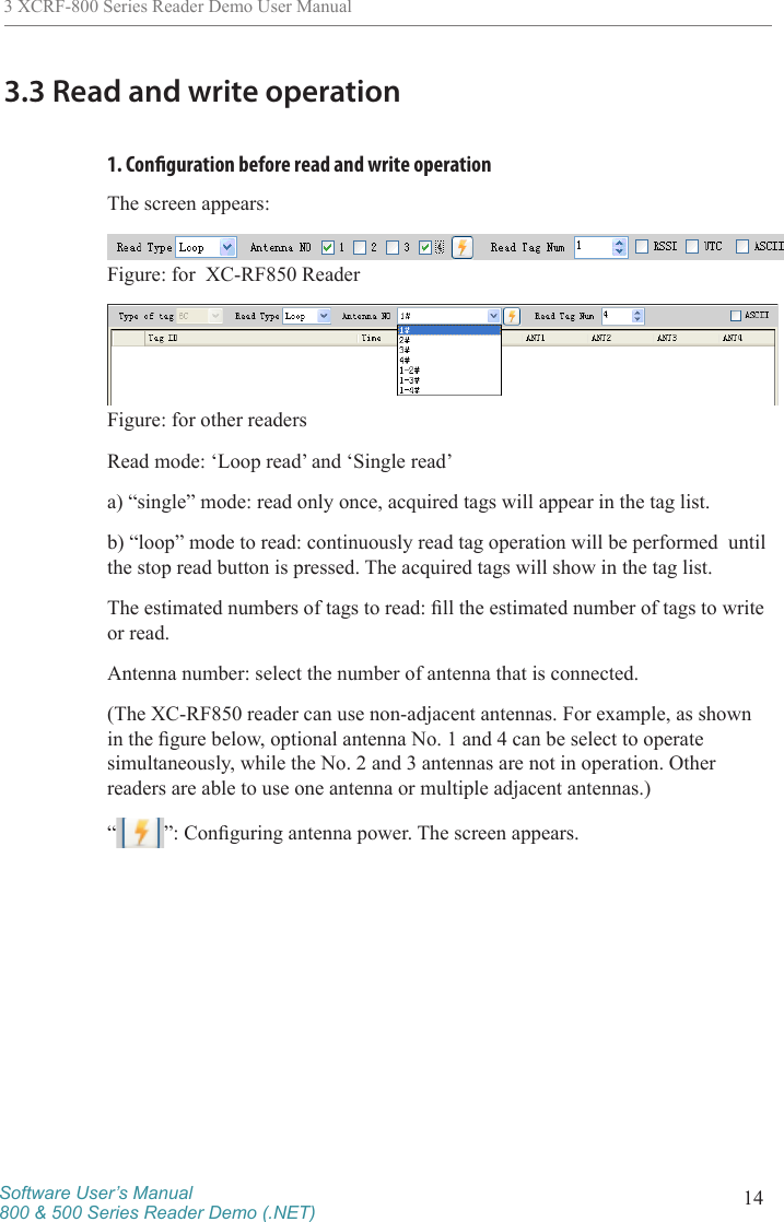
![Software User’s Manual800 & 500 Series Reader Demo (.NET) 93 XCRF-800 Series Reader Demo User Manual3 XCRF-800 Series Reader Demo User Manual3.1 Running the read demoClick [Start]—[Programs], select Invengo Demo v1.83 program group, and click ‘XCRF-800(500) Demo v1.83’ to run the XCRF-800(500) Series reader Demo. Or double click ‘XCRF-800(500) Demo v1.83’ on the desktop run the XCRF-800(500) Series reader Demo.Click ‘Start 800 Series Reader Demo’: The screen appears:](https://usermanual.wiki/Invengo-Information-Technology/XC-RF850/User-Guide-2275384-Page-14.png)