Invengo Information Technology XC-RF850 Reader User Manual
Invengo Information Technology Co., Ltd. Reader Users Manual
Users Manual

Invengo Information Technology Co., Ltd.
Software User’s Manual
800&500 Series Reader Demo (.NET)
Version:V1.83

Preface
This demo is applicable to the Invengo product models including, but not limited to:
XC-RF850 Reader
This manual provides the information on the software installation, operation and
other features.
This manual’s version number is V1.83, printed on 2013-01-16 .
and logos are owned by Invengo Information Technology
Co., Ltd.
Content
1 Overview........................................................................................1
1.1 About Demo Software ......................................................................1
1.2 System Requirements ......................................................................1
1.3 Technical Terms ................................................................................1
2 Installing demo software .............................................................2
3 XCRF-800 Series Reader Demo User Manual ............................ 9
3.1 Running the read demo ...................................................................9
3.2 Connecting/disconnecting XCRF-800 Series reader ..................10
3.3 Read and write operation ..............................................................14
3.4 Conguration menu .......................................................................21
3.5 Function Menu ................................................................................ 30
4 Troubleshooting .........................................................................36
Appendix ........................................................................................38

Safety Instructions
Your safety is extremely important. Read and follow all warnings and cautions in
this document before handling and operating Invengo equipment. You can be
seriously injured, and equipment and data can be damaged if you do not follow
the cautions.
Warning
A warning alerts you of an operating procedure, practice, condition, or statement
that must be strictly observed to avoid death or serious injury to the persons
operating on the equipment.
Notice
A Note either provides: extra information about a topic or alerts to an operating
procedure, practice, condition, or statement or corruption or loss of data, or
contains special instructions for handling a particular condition or set of
circumstances.

Software User’s Manual
800 & 500 Series Reader Demo (.NET) 1
1 Overview
1 Overview
1.1 About Demo Software
The Demo software is used to set system parameters and perform write/read
operation on Invengo XCRF-800 series and XCRF-500 series reader and ISO
compliant transponders
1.2 System Requirements
●Supported Operating Systems
Windows 2000 Service Pack 3; Windows Server 2003; Windows XP Service
Pack 2; Windows Vista; Windows 7
These systems are 32-bit operating system. The USB driver does not support 64-
bit OS for the time being..
●Required Software
Windows Installer 3.0 is required. Windows Installer 3.1 or later is
recommended. IE 5.01 or later is required: for installing the .NET Framework.
●Recommended hardware requirements
CPU: Pentium 4 at 1.7 GHz or above
Memory: min. 512MB
1.3 Technical Terms
TID: Tag identier
EPC: Electronic product code
RSSI: Received signal strength indicator
LBT: Listen before Talk
DRM: Dense reader mode
Q: Slot count parameters
EAS: Electronic Article Surveillance
QT: innovative privacy features of Impinj Monza 4 tag chip
Software User’s Manual
800 & 500 Series Reader Demo (.NET) 2
2 Installing demo software
2 Installing demo software
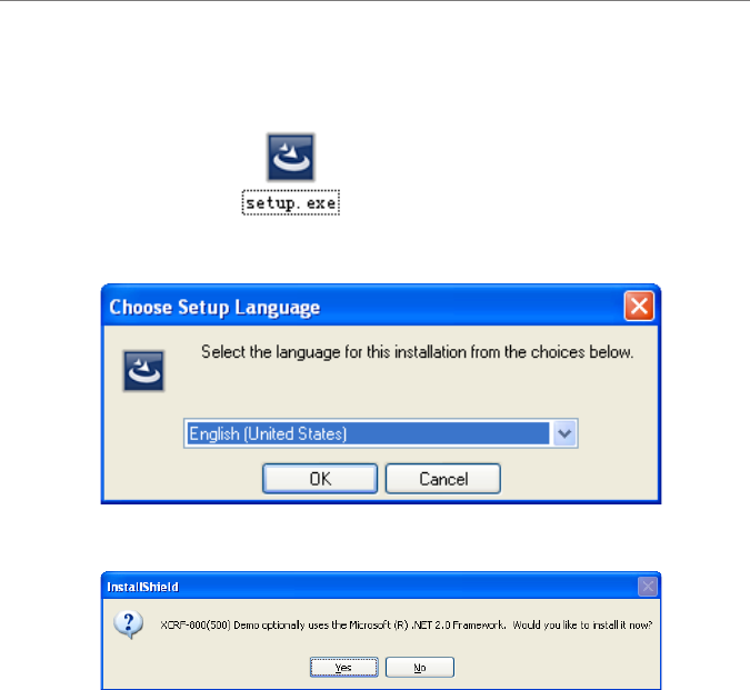
Click’setup.exe’
Choose English and click OK button.
Installation window will pop up if .NET Framework 2.0 is not installed.
Click ‘Yes’.
Software User’s Manual
800 & 500 Series Reader Demo (.NET) 3
2 Installing demo software
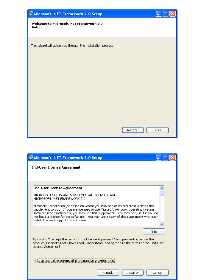
Click ‘Next’. Please refer to the following picture:
Accept and click ‘Install’ to continue setup.
Software User’s Manual
800 & 500 Series Reader Demo (.NET) 4
2 Installing demo software
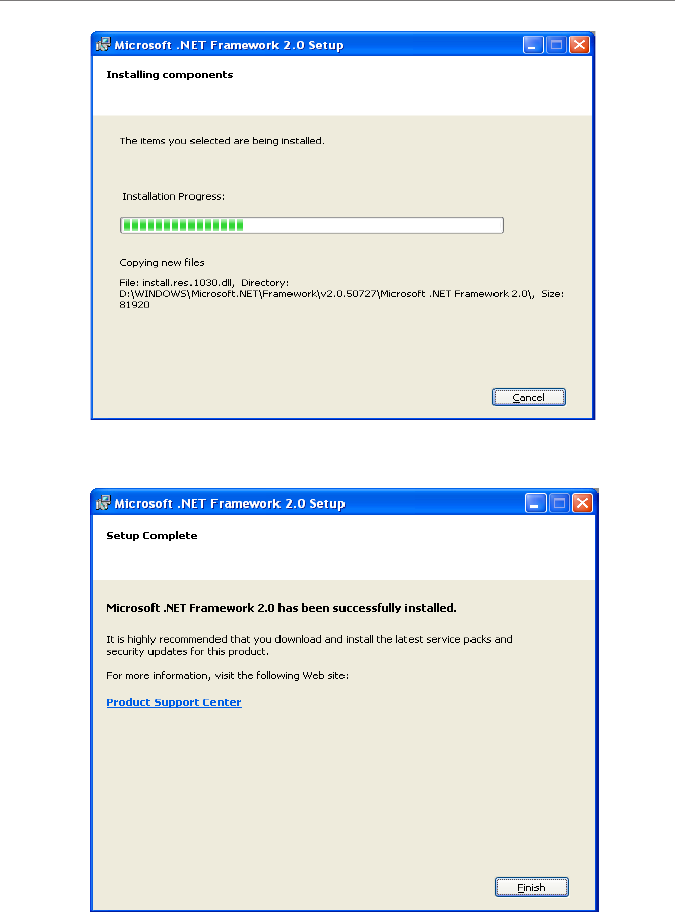
Program will display the following screen directly if .NET Framework 2.0 has
been installed.
Click ‘Finish’.
Software User’s Manual
800 & 500 Series Reader Demo (.NET) 5
2 Installing demo software
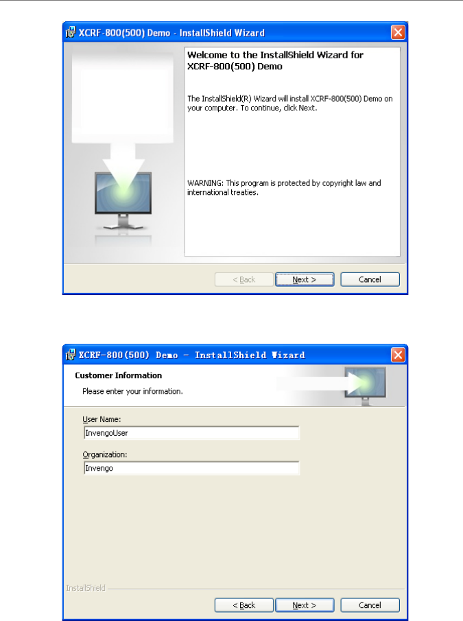
Click ‘Next’.
Please enter your information and click ‘Next’.
Software User’s Manual
800 & 500 Series Reader Demo (.NET) 6
2 Installing demo software
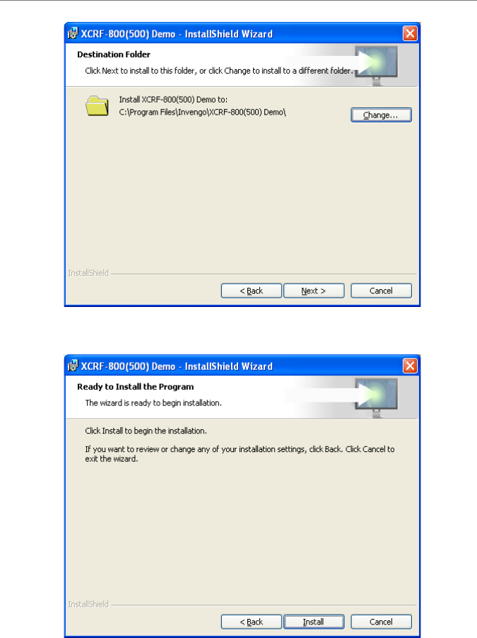
Select installation directory, click ‘Next’
Click ‘Install’
Software User’s Manual
800 & 500 Series Reader Demo (.NET) 7
2 Installing demo software
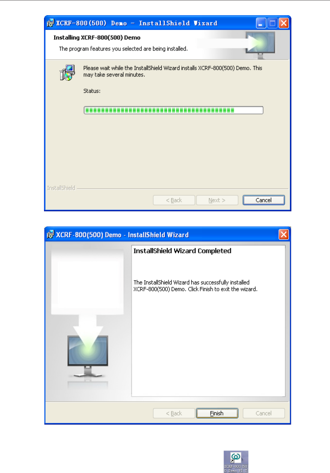
Click ‘Finish’ to close installation.
After successful installation, the desktop shortcut " "will appear
Software User’s Manual
800 & 500 Series Reader Demo (.NET) 8
3 XCRF-800 Series Reader Demo User Manual
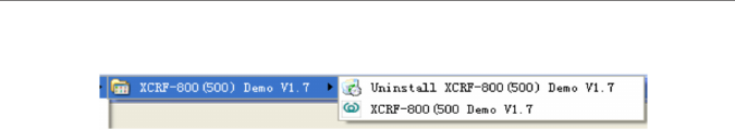
The appropriate Start menu shortcuts will appear, as shown:
Software User’s Manual
800 & 500 Series Reader Demo (.NET) 9
3 XCRF-800 Series Reader Demo User Manual
3 XCRF-800 Series Reader Demo User
Manual
3.1 Running the read demo
Click [Start]—[Programs], select Invengo Demo v1.83 program group, and click
‘XCRF-800(500) Demo v1.83’ to run the XCRF-800(500) Series reader Demo.
Or double click ‘XCRF-800(500) Demo v1.83’ on the desktop run the XCRF-
800(500) Series reader Demo.
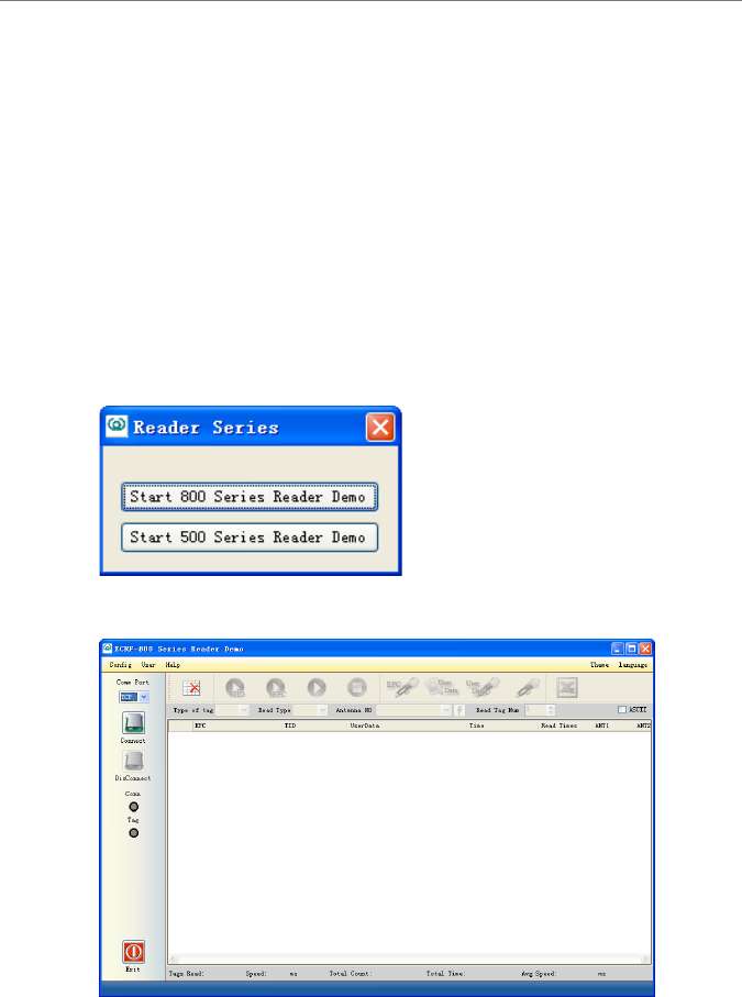
Click ‘Start 800 Series Reader Demo’:
The screen appears:
Software User’s Manual
800 & 500 Series Reader Demo (.NET) 10
3 XCRF-800 Series Reader Demo User Manual
3.2 Connecting/disconnecting XCRF-800 Series reader
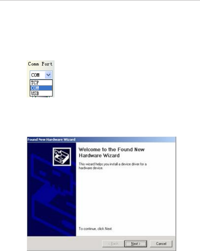
1. Selecting communication mode
Three communication modes, including TCP/IP, COM (RS232) and USB, are
available. Click ‘Comm. Port’ to select the desired communication mode.
Notice: USB option will be available when USB device and the driver are
installed: Install the USB driver as follows:
Connect the reader with a USB cable, and apply power to the reader, the screen
of ‘new hardware found’ appears.
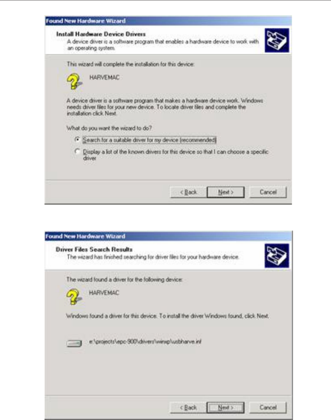
Click ‘Next’
Software User’s Manual
800 & 500 Series Reader Demo (.NET) 11
3 XCRF-800 Series Reader Demo User Manual
Click ‘Next’
Click ‘Next’
Software User’s Manual
800 & 500 Series Reader Demo (.NET) 12
3 XCRF-800 Series Reader Demo User Manual
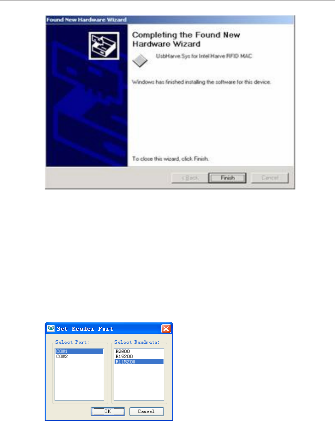
Click ‘Finish’.
The message of ‘New hardware is installed and ready for use’ displays. When
the installation of driver is completed, the computer can communicate with the
XCRF-800(500) Series reader via USB port. 2. Click ‘Connect’ button after the
desired communication mode is selected.
3. Conguring COM port parameters
The communication mode COM should be selected. Select the desired COM port
and baud rate as the screen appears below, and click ‘OK’ to connect the XCRF-
800(500) Series reader.
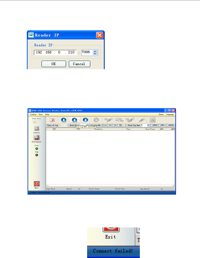
4. Conguring IP address
The communication mode TCP should be selected as the screen appears below.
Input the reader’s IP address, and congure the PC network area which should
be identical with that of the reader (defaulted as 192.168.0.210). The default port
number is 7086. And click ‘OK’ to connect the XCRF-500 Series reader. When
Software User’s Manual
800 & 500 Series Reader Demo (.NET) 13
3 XCRF-800 Series Reader Demo User Manual
the IP addresses of the PC and the reader are not in different segment, enter
mapped IP address and port number or the reader and click “OK Connect” button
to connect.
5. Successful connection
After the successful connection, the Conn icon on the following screen turns
green, and the software status bar indicates that ‘successful connection’. The
screen appears.
6. Connection failed
‘Connect failed’ message will appear on the software status bar.
7. Disconnecting the XCRF-800 Series reader
Click ‘Disconnect’ button, and the Conn icon turns gray. ‘Disconnected’
message will appear on the software status bar.
Software User’s Manual
800 & 500 Series Reader Demo (.NET) 14
3 XCRF-800 Series Reader Demo User Manual
3.3 Read and write operation
1. Conguration before read and write operation
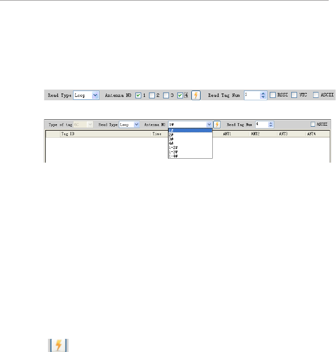
The screen appears:
Figure: for XC-RF850 Reader
Figure: for other readers
Read mode: ‘Loop read’ and ‘Single read’
a) “single” mode: read only once, acquired tags will appear in the tag list.
b) “loop” mode to read: continuously read tag operation will be performed until
the stop read button is pressed. The acquired tags will show in the tag list.
The estimated numbers of tags to read: ll the estimated number of tags to write
or read.
Antenna number: select the number of antenna that is connected.
(The XC-RF850 reader can use non-adjacent antennas. For example, as shown
in the gure below, optional antenna No. 1 and 4 can be select to operate
simultaneously, while the No. 2 and 3 antennas are not in operation. Other
readers are able to use one antenna or multiple adjacent antennas.)
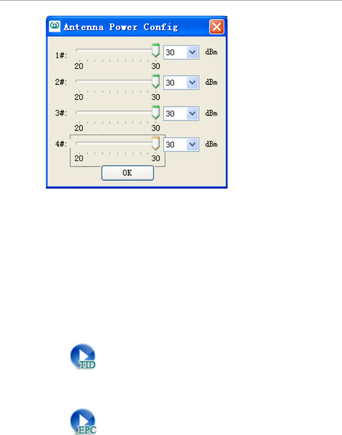
“”: Conguring antenna power. The screen appears.
Software User’s Manual
800 & 500 Series Reader Demo (.NET) 15
3 XCRF-800 Series Reader Demo User Manual
Set the power antenna/s, and click “OK”.
RSSI: the antenna signal strength will display when selected. (Readers of
specic models support this function.)
UTC: UTC time will display when selected. (Readers of specic models support
this function.)
ASCII: ASCII format will be used to write tag data when selected; TID which
is of 16 hex will be unaltered. 16 hex format will be used to write tag data when
de-selected.
2. Read TID
Click’ ‘to read TID number
3. Read EPC number
Click’ ‘button to read EPC number .
Software User’s Manual
800 & 500 Series Reader Demo (.NET) 16
3 XCRF-800 Series Reader Demo User Manual
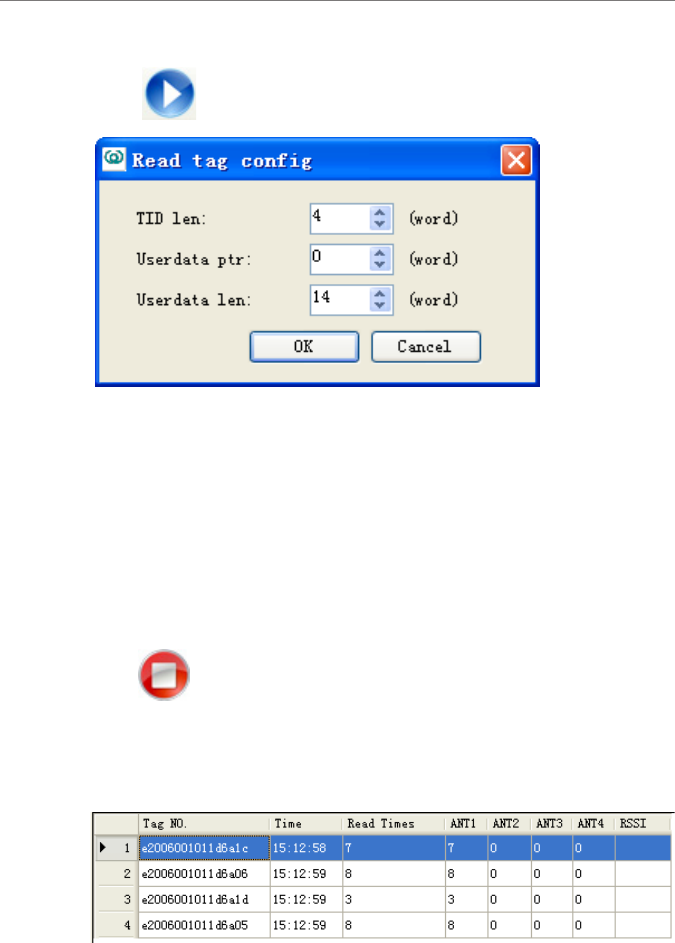
4.General read
Click“ ”button to cong reading parameters.
TID len: species the length of the TID to read, usually set to 4 words (8 byte).
Userdata ptr: species the offset of the user data to read. Userdata ptr must be
within the memory bank.
Userdata len: species the length of the user data to read. The sum of the offset
and data length must be within the size of the memory bank.
Click “OK” to set.
5. Stop read
Click’ ‘Stop read tag (stop read tag operation of 2,3 and 4)
6. Read tag data result
Show the data. The screen appears.:
Software User’s Manual
800 & 500 Series Reader Demo (.NET) 17
3 XCRF-800 Series Reader Demo User Manual
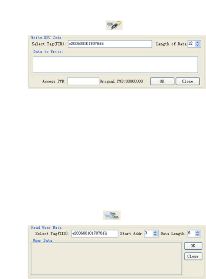
7. Write EPC data
Select a data in the data list. Click ‘ ’ button and the screen appears:
Select tag (TID): click a data in the data list, and the TID number will be
automatically added into the text box. (EPC number will be displayed in event of
read EPC number.)
Write data byte: The length of data byte to write which is even number will be
automatically calculated according the input characters.
Write EPC data: input the hexadecimal digit (A byte consists of two characters)
or ASCII string in the text box. 0 will be automatically added if the number of
input characters is odd.
Tag access password: input tag the access password, defaulted as ‘00000000’.
OK: conrm to write EPC data.
Close: close the write EPC data screen.
8. Read user data
Select a tag in the data list, click ‘ ’ button and the screen appears:
Select tag (TID): click the data in the data list and the TID number will
automatically added to the text box.
Software User’s Manual
800 & 500 Series Reader Demo (.NET) 18
3 XCRF-800 Series Reader Demo User Manual
Start address: in byte, start address is the start location for reading user data. (even
number).
Data length: the data length is calculated from the start address, the byte number
of the data to read (even number)
Tag user area data: read data results.
OK: conrm to read user area data.
Close: close the read user data area screen.
Tip: EPC code defaults to 12 bytes. The length of EPC data area of tags from
different vendors or of different models may vary, of which the maximum is 30
bytes.
Tip: “Start address” + “data length” should not exceed the maximum number of
bytes of user data.
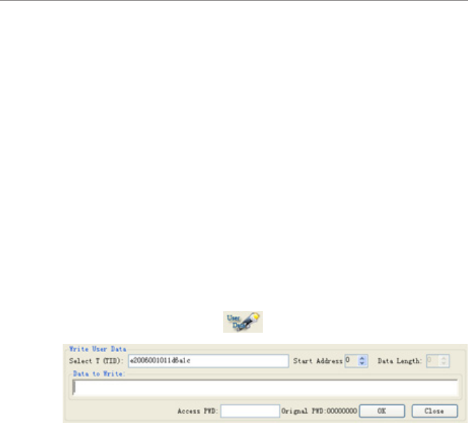
9. Write user data
Select the data is the list, click ’ ’ button, and the screen appears:
Select tag (TID): Select the data is the list, and the TID number will
automatically be added to the text box. (If the operation is to read EPC, it will be
the EPC number.)
Start address: in byte, the start address is the start point (even number) of the
user data area to write.
Data length: the length will be calculated according to the input characters. The
byte number of the data to write should be even.
Write data: input the hexadecimal digit (A byte consists of two characters) or
ASCII string in the text box. The number of characters input should not be odd,
and should correspond with the byte number congured.
Write: Conrm to write the user area data.
Close: close the write user data area screen.
Software User’s Manual
800 & 500 Series Reader Demo (.NET) 20
3 XCRF-800 Series Reader Demo User Manual
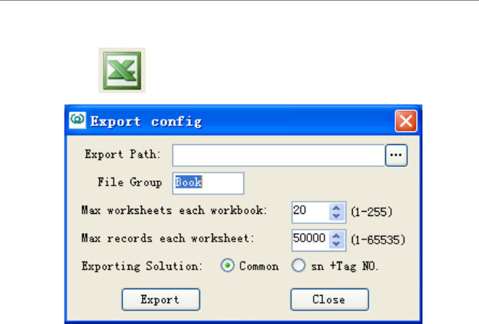
11. Exporting data
Click’ ’ button, and the screen appears:
Export Path: the directory to save the imported le. Click the ‘...’ button to
explore the folders.
File Group: input the le names, and the les exported will be automatically
named by adding a sequent number.
Export Solution: ‘Common’ enables the export of data listed in the box, and ‘sn
+ Tag NO.’ enables the export of sequence number + tag number.
Export: exporting data.
Close: close Export Cong box.
Software User’s Manual
800 & 500 Series Reader Demo (.NET) 21
3 XCRF-800 Series Reader Demo User Manual
3.4 Conguration menu
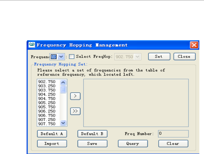
1. Frequency hopping management
a) Frequency range:
select ‘CN’, ‘US’ or ‘EU’ to switch the frequency range. If the frequency range
is selected, the frequency of the reader will switch to the standard frequency of
the selected region. (Not supported by all the XCRF-800 Series readers) (“CN”:
Chinese standard band; “US”: North American Standard Band; “EU”: EU
standard band)
Selecting frequency hopping: select the desired frequency point in the frequency
range box.
b) Conguring frequency hopping option:
The left list box includes the frequency point data of the frequency range, and
the right box includes the frequency point list, showing the selected frequency
point or frequency point query results.
>: add a frequency point to the frequency point list.
>>: add the frequency point in the list box to the frequency point list, or add the
maximum frequency points that the XCRF-800 Series reader supports.
Default option A: showing the frequency point of default option A listed in the
frequency point list.
Software User’s Manual
800 & 500 Series Reader Demo (.NET) 22
3 XCRF-800 Series Reader Demo User Manual
Default option B: showing the frequency point of default option B listed in the
frequency point list.
Frequency point number: listing the frequency point number in the frequency
point list.
Import option: import the external frequency point options saved by demo
software.
Storing option: store the frequency point of the frequency point list in the
external option le.
Querying frequency point: query the current operating frequency point of the
XCRF-800 Series reader; show the current operating frequency point of the
XCRF-800 Series reader in the frequency point list.
Clear: clearing the data of frequency point list will not change the conguration
of frequency point.
Conguring: congure the data of frequency point list or the selected frequency
point in frequency hopping selection list to the XCRF-800 Series reader.
Close: close the screen.
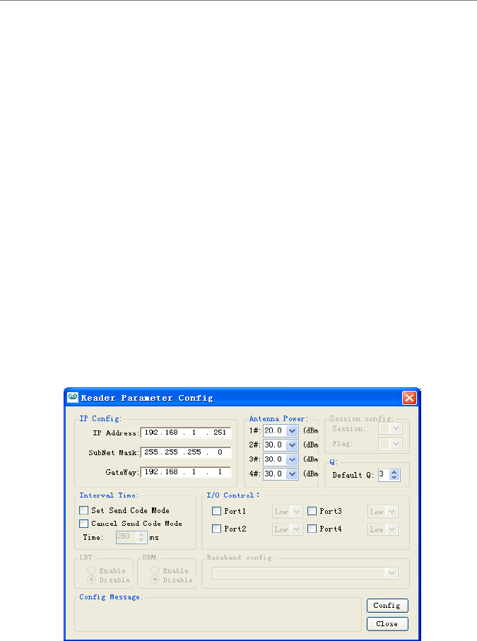
2. Frequency hopping management
The current conguration of the XCRF-800 Series reader display in the screen
appears above. If one of the congurations is not available, it is probably caused

Software User’s Manual
800 & 500 Series Reader Demo (.NET) 23
3 XCRF-800 Series Reader Demo User Manual
by failed query, possibly indicating the feature to operate is not supported. Close
screen is recommended.
Conguring IP: modify the IP if needed
Adjusting antenna power: adjust if needed. Or select the desired value (20-30).
I/O control: conguring the ports.
Session cong: conguring the session.
Q value: the XCRF-800 Series reader’s default Q value.
Conguring Session: Inventory session and ag conguration
Code sending interval: the time interval the multiple readers require to send code
which is supported by XCRF-804 only.
LBT: listen before talk.
DRM: dense reader mode switch.
Baseband data rate: baseband data rate setting
Conguration status: Click the button to congure the operation, and execution
result will be displayed.
Conguration: add the conguration data to the XCRF-800 Series reader.
Close: closing the screen.
Software User’s Manual
800 & 500 Series Reader Demo (.NET) 24
3 XCRF-800 Series Reader Demo User Manual
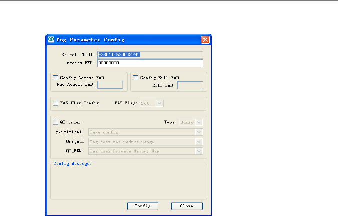
3. Conguring tag parameters
Select a data is the data list. And the TID will automatically be added to the ‘select
tag (TID)’ text box.
Select TID: The system will automatically add the number of selected tags to the
“Select Tag (TID)” text box. Input the desired number of tags to operate.
Tag access password: input tag access password, the default is: ‘00000000’.
Conguring access password: select and input new password.
Conguring kill password: select and input new password.
Conguring EAS: select to congure or cancel EAS bit position conguration.
QT command: QT command can be queried and congured when selected.
(Specic models of reader support this command.)
Conguring message: Click the Congure button to congure the operation,
results will be shown
Conguring: congure the desired options.
Close: closing the screen.
Software User’s Manual
800 & 500 Series Reader Demo (.NET) 25
3 XCRF-800 Series Reader Demo User Manual
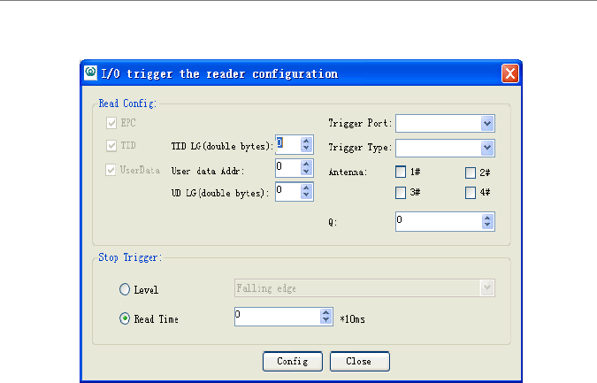
4. Setting Read tag by I/O input trigger (applies to XCRF-807 reader)
TID LG (doule bytes): Enter TID length of the tag to operate.
User data Addr (double bytes): in byte, starting address for the user data area to
read (even number).
UD LG (double bytes): enter the length of user memory (even number).
Trigger port: select the trigger port.
Trigger type: Never, falling edge, rising edge.
Antenna: select the number of antenna to operate.
Q: set the Q value when a read operation is performed.
The conditions to terminate read operation:
Level: the level of the input ports used to determine whether to stop a read
operation.
Read time: read operation trigger, by a certain time interval delay, stop a read
operation.
Cong: save the conguration changes to the reader.
Close: close the window.
Software User’s Manual
800 & 500 Series Reader Demo (.NET) 26
3 XCRF-800 Series Reader Demo User Manual
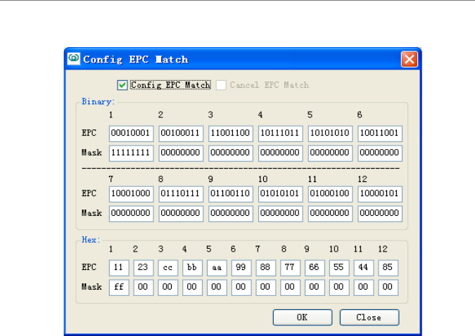
5. EPC matching conguration
Binary Code and hexadecimal digit are supported.
EPC: EPC number data.
Mask code: data to match, 0 indicates un-matched masked code.
Conguring EPC matching: select the text box and edit.
Canceling EPC matching: select and cancel the matching.
OK: conrm or cancel the conguration according to the text box.
Close: closing the screen.
Software User’s Manual
800 & 500 Series Reader Demo (.NET) 27
3 XCRF-800 Series Reader Demo User Manual
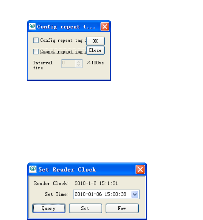
6. Filtering repeatedly acquired tag conguration.
Repeatedly acquired tags ltering by time interval can be congured or canceled.
Conguring repeated tag ltering: select and congure.
Cancel repeated tag ltering: select and congure.
Interval time: input or select the desired interval time.
OK: Congure or cancel conguration.
Close: closing the screen.
7. Setting reader clock
Reader clock can be set in the above screen.
Query: query the reader’s current time.
Set: congure the reader’s current time. Enter the current time directly in the
input box or click the drop-down button to select the time in the input box.
Current time: the current time of PC is displayed if "now" is clicked.
Software User’s Manual
800 & 500 Series Reader Demo (.NET) 28
3 XCRF-800 Series Reader Demo User Manual
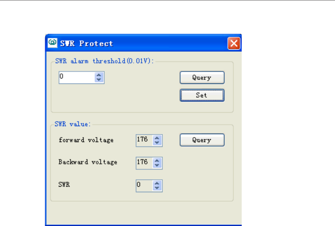
8. VSWR protection (only applies to XCRF-807 reader)
Query (VSWR warning threshold): Query the current standing wave ratio
warning threshold
Set: Setting SWR warning threshold
Query (standing wave ratio): forward volatage, backward voltage, and standing
wave ratio.
Software User’s Manual
800 & 500 Series Reader Demo (.NET) 29
3 XCRF-800 Series Reader Demo User Manual
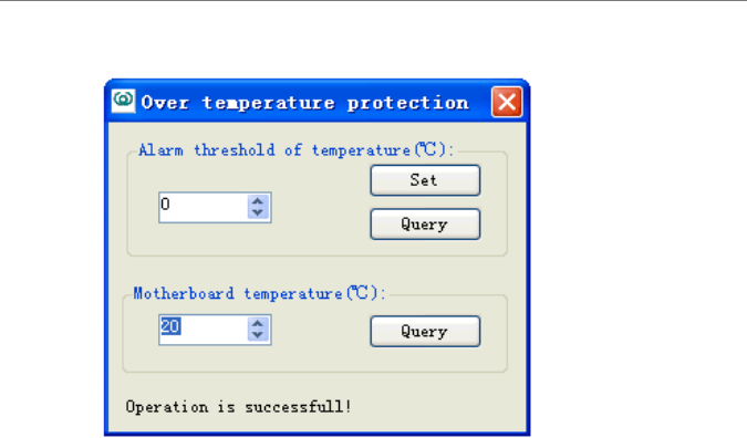
9. Over-temperature protection (only applies to XCRF-807 reader)
Set: The over-temperature warning threshold saved to the reader.
Query (over-temperature warning threshold): Query over-temperature warning
threshold.
Query (Motherboard temperature): The current board temperature.
10. Close
Close the screen.
Software User’s Manual
800 & 500 Series Reader Demo (.NET) 30
4 XCRF-500 Series Reader Demo User Manual
3.5 Function Menu
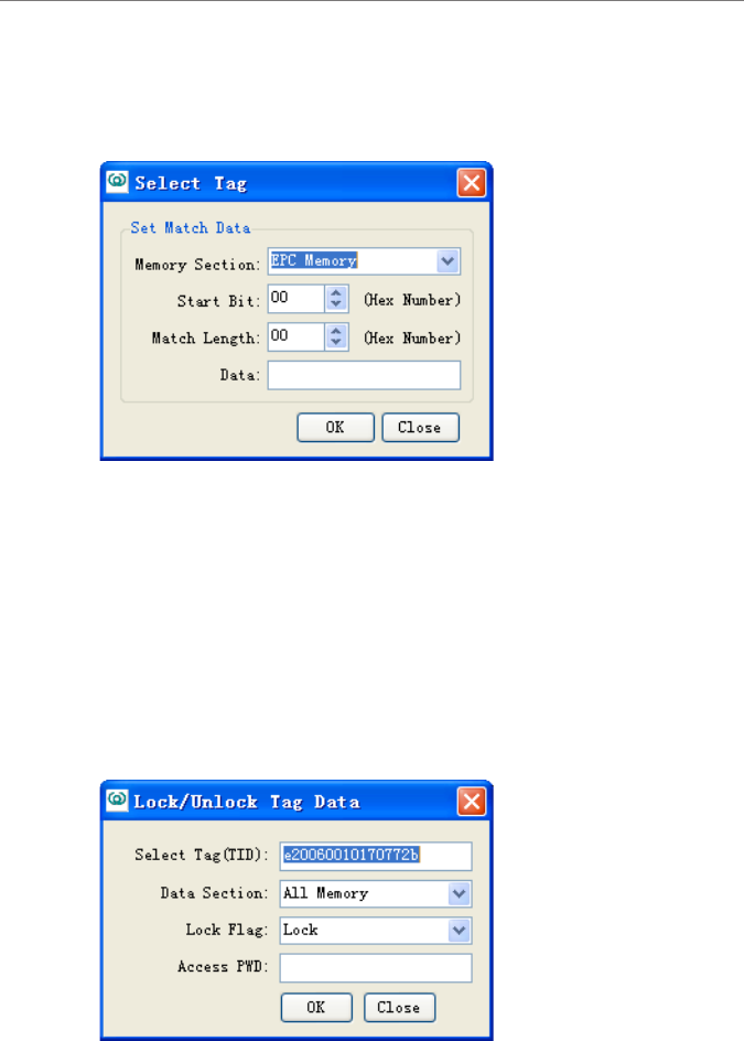
1. Select and read tags
Memory Section: select ‘TID Memory’, ‘EPC Memory’ and ‘user Memory’
Start Bit: the start position of the memory, in byte.
Match Length: matching per bit.
Memory Section: the section to match.
OK: conrm the conguration.
Close: close the screen.
2. Lock tag data area
Select the data is the list. The TID will automatically be added to the ‘select tag
Software User’s Manual
800 & 500 Series Reader Demo (.NET) 31
4 XCRF-500 Series Reader Demo User Manual
(TID)’ text box. TIDs can be set by user.
Select tag (TID): input the tag TID.
Data Section: select ‘All Memory’ , ‘TID", ‘EPC’ , ‘user’ , ‘access password , or
‘kill password’ .
Lock Flag: select ‘lock’ or ‘unlock’.
Access FWD: input tag access password. The default is: ‘00000000’.
OK: conrm conguration.
Close: close the screen.
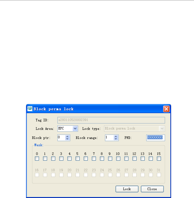
3. Block Permanent Lock
Lock Area: select the block to lock.
Address of start block (BlockPtr) : 16 blocks comprise of a unit. 0x00 indicates
that operation starts from block 0, and 0x01 indicates block 16.
Block permanent lock range (BlockRange): range of block permanent locks,
from the starting block address (BlockPtr) to (16 * BlockRange-1), the minimum
is 1.
Mask (Mask): each one corresponds to a block for permanent lock operation.
1 performing a permanent lock, 0 maintaining the original lock state. BlockPtr
Mask corresponds to the highest position, (16 * BlockRange- 1) corresponds to
the lowest level.
Software User’s Manual
800 & 500 Series Reader Demo (.NET) 32
4 XCRF-500 Series Reader Demo User Manual
Lock: to complete lock operation.
Close: close the screen.
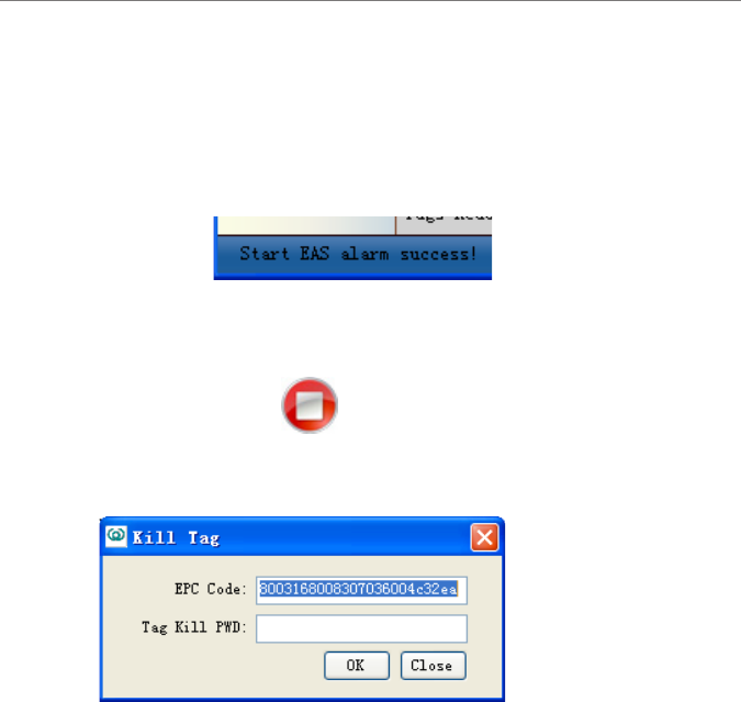
4. Activate EAS Alarm
EAS alarm will be activated when specic tags in preset location are identied.
EAS enabled:
Conguring EAS: See Section 3.4
Alarm setting: 1. Visual alarm; 2. Audio alarm.
Disabling EAS: click“ ”.
5. Kill tag
Select the data in the list. The EPC will automatically be added to the ‘EPC
number ‘text box.
EPC Code: input the tag EPC.
Tag Kill PWD: input the tag access password. The default is: ‘00000000’.
OK: Conrm the conguration.
Close: close the screen.
Software User’s Manual
800 & 500 Series Reader Demo (.NET) 33
4 XCRF-500 Series Reader Demo User Manual
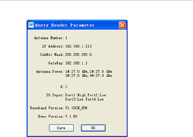
6. Querying the XCRF-800 Series reader parameters.
Save: save the information in the external le.
OK: Close the screen
Software User’s Manual
800 & 500 Series Reader Demo (.NET) 34
4 XCRF-500 Series Reader Demo User Manual
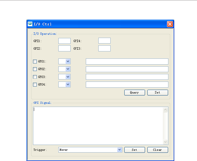
7. IO control (GPI signal monitoring applies to XCRF-807 reader)
Query: query info of I/O port.
Set: set the level of output port: high level or low level.
Set (GPI signal change monitoring): Monitoring GPI signal changes.
Trigger (GPI signal change monitoring):
Select the condition to trigger GPI signal change monitoring:
by level change
by falling edge
by rising edge
not to be triggered by level change
Clear (GPI signal change monitoring): Clear GPI signal change monitoring
information.

Software User’s Manual
800 & 500 Series Reader Demo (.NET) 35
4 XCRF-500 Series Reader Demo User Manual
8. Beep
A warning tone gives off during operation when it is enabled. For example: a
beep tone gives off when read tag is performed.

Software User’s Manual
800 & 500 Series Reader Demo (.NET) 36
Appendix
4 Troubleshooting
1 Serial Port Connection Failure
Check whether the COM port of the reader is connected with the corresponding
port. The serial link baud rate of computer and reader must be identical with that
of reader. Whether the serial port cable is correctly connected. Disconnection or
loose connection may disable the instructions from the computer to the Reader;
2 Network Port Connection Failure
The default IP address is 192.168.0.210. The connection between the Reader and
PC can be established if the PC’s IP address and Reader’s IP address are in the
same network, segment (e.g. 192.168.0.XXX), or of connected networks, The
Reader IP can be set by using Demo software in a computer with RS-232 serial
port if the IP address is missing.
3 USB Port Connection Failure
Check whether the PC has identied such USB Device. If identication is failed,
please install USB driver by referring to Section 3.2.
Check whether the USB cable is correctly connected, as disconnection or loose
connection may disable the instructions from the computer to the Reader.
4 Unable to Read Tags
Check the serial port cable, USB cable or network cable is correctly connected.
Disconnection or loose connection may disable the instructions from the
computer to the Reader.
Check whether the antenna’s SMA connector is tight, and whether the tag is
damaged.
Whether the Antenna number on the main interface is correctly selected and
whether it is identical with port number of external antenna.
Whether the ‘Number of Tags to be Read’ is correctly set. (It shall be
approximate to the number of the tags within the antenna’s coverage)

Software User’s Manual
800 & 500 Series Reader Demo (.NET) 37
Appendix
5 How to operate readers remotely?
Reader is equivalent to a network terminal. Demo software can be connected
with IP address port (For connecting XCRF-800 Series reader see IP connection
of 3.2; for IP address settings, see 3.4 in reader parameter settings; for connecting
XCRF-500 Series reader, see IP Settings of 4.2; IP address settings, see 4.4 IP
settings; reader port number is xed at 7086); the reader can be operated when
connection is established .
6 Must IP address range be reserved for reader?
Every reader needs an IP. IP address of reader can be set, ensuring that there is
not |IP address conict between reader and other network devices. Reader does
not automatically check the IP conict.
7 How to cancel configuration parameters operation, such as:
access password, kill password, and EAS?
For setting access password and kill password, see 4.3.9 and 4.3.10. Access
password and kill password will be valid when Locking tag (4.3.11) is
completed. For EAS conguration settings see 4.3.13, 4.3.14 and 6.1.14. Only
one tag will set off alarm when EAS function. In other words, EAS is designed
to set off on the alarm of the EAS tag with EAS.
8 How to set the EPC matching?
EPC matching is valid for the 12-byte EPC number. EPC matching instructions
include three parameters; one to set or cancel the parameter, one to match
EPC parameter, and one to match mask parameter. Matching is based on bit
match. Matching a mask of which one bit is 1 will be effective. Matching a
mask of which one bit is 0 will not be effective. For example, to read the EPC
of which the rst 2 bytes is “1234”, set the parameters to match the EPC code
as “12340000000000000000” (16 hex), and set the matching mask parameter
as “ffff00000000000000000000” (16 hex). This conguration enables the
acquisition of tags of “1234 ********************”.
For additional information, contact your Invengo representative.

Software User’s Manual
800 & 500 Series Reader Demo (.NET) 38
Appendix
Appendix
The CD-ROM contains setup installer, USB driver, API (including Invengo.
CongFileClass.dll, Invengo.Order.dll, Invengo.XCRFAPI.dll, Invengo.
XCRFReader.dll, log4net.dll, FreqType.xml, language folder) and so on.
API interface function is the interface platform for the reader and background
software which provides help for system integrators and end users. For addtional
information on API interface function, please refer to .NET API Technical
Reference Manual.

Warning
This device complies with Part 15 of the FCC Rules. Operation is subject to
the following two conditions: (1) this device may not cause harmful interference,
and (2) this device must accept any interference received, including interference
that may cause undesired operation.
changes or modifications not expressly approved by the party responsible for
compliance could void the user's authority to operate the equipment.
NOTE: This equipment has been tested and found to comply with the limits for a
Class B digital device, pursuant to Part 15 of the FCC Rules. These limits are
designed to provide reasonable protection against harmful interference in a
residential installation. This equipment generates, uses and can radiate radio
frequency energy and, if not installed and used in accordance with the
instructions, may cause harmful interference to radio communications. However,
there is no guarantee that interference will not occur in a particular installation.
If this equipment does cause harmful interference to radio or television reception,
which can be determined by turning the equipment off and on, the user is
encouraged to try to correct the interference by one or more of the following
measures:
-- Reorient or relocate the receiving antenna.
-- Increase the separation between the equipment and receiver.
-- Connect the equipment into an outlet on a circuit different
from that to which the receiver is connected.
-- Consult the dealer or an experienced radio/TV technician for help.
RF Exposure Statement
To maintain compliance with FCC’s RF Exposure guidelines, This equipment
should be installed and operated with minimum distance between 20cm the
radiator your body: Use only the supplied antenna.

Corporate Headquarters
Invengo Information Technology Co., Ltd.
3/F, No.T2-B, High-tech Industrial Park South,
Shenzhen 518057, China
www.invengo.cn
Tel: (86) 755 26525585
Fax: (86) 755 26525277
intl@invengo.cn
US Subsidiary
Invengo Technology Corp.
12801 Worldgate Drive, Suite 500
Herndon, VA 20170 U.S.A
www.invengo.com
Tel: 1 703 793 0085
Fax: 1 703 871 3901
sales@invengo.com