Invengo Information Technology XC2903 UHF RFID Reader User Manual XC2903 software user guide
Invengo Information Technology Co., Ltd. UHF RFID Reader XC2903 software user guide
UserManual.wiki
>
Invengo Information Technology
>
XC2903 User Manual
Users Manual
Navigation menu
Upload a User Manual
Namespaces
Wiki Guide
HTML
PDF
Info
Views
User Manual
Discussion / Help
Navigation
![Figure 2-2 RFID interface l Clear: To clear the scanning results in the table. l Read: To perform loop reading. l Option: To set reader parameters and tag operations. Click the button “Scan” (the button will be transferred to “Stop” after clicking), the reader will perform loop scanning. That means a tag will be scanned for many times. Then, the data and scanning times of the tag will be listed in the table. The loop scanning will not be stopped until you click the button “Stop” (the button will be transferred to “Scan” after clicking). The example is shown as figure 2-3. Note: scanning can also be performed by pressing the key [SCAN] on the RFID handheld reader. Figure 2-3 read As shown in the figures above, the scanning state (including reading time, reading rate and tag amount) will be displayed under the table. If the data of the last time is not cleared, the current scanning data will be added to the previous data. In the same word, the scanning times will be added to the value displayed at the last stop instead of 0. If you would like to count the scanning times from 0, please click “Clear”. Then, the data of the last scanning will be cleared and could perform a new time of scanning. The software is set to read TID of tags in default. The reading settings could be changed in “Read set”. Click “Option”, the interface is shown as figure 2-4. Figure 2-4 RFID option The read settings and other settings will be introduced in detail below.](https://usermanual.wiki/Invengo-Information-Technology/XC2903/User-Guide-2289714-Page-4.png)
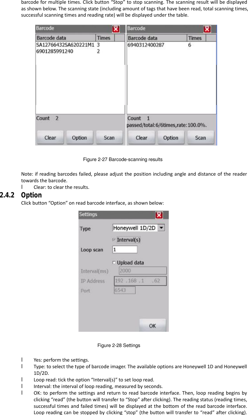
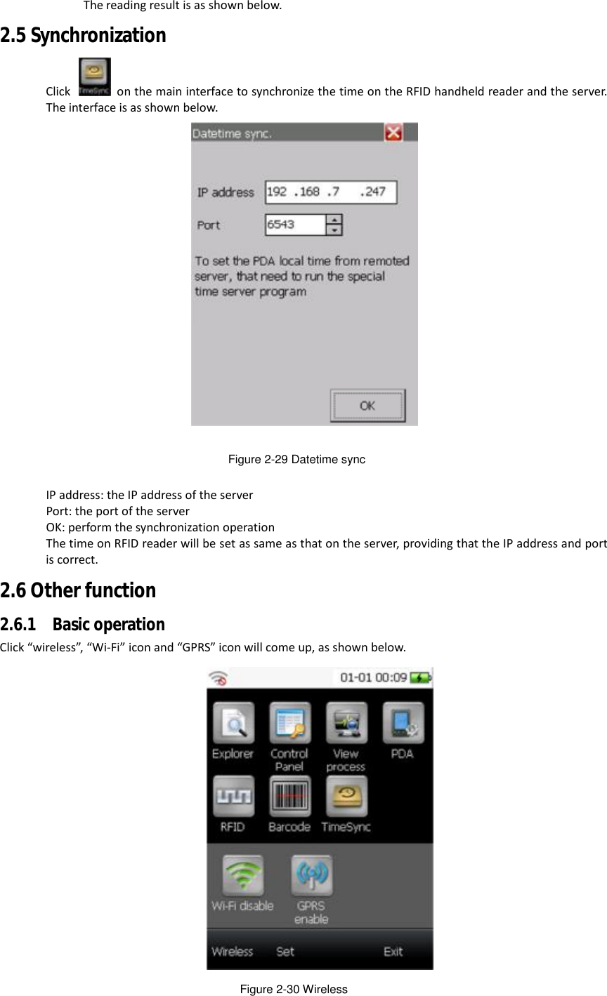
![Figure 2-25 Version l Software version: the version number of software. l Operation System: the version number of the operation system. l Inner System: the version number to distinguish customization of operation system. 2.4 Read Barcode The interface is to display how RFID handheld reader reads barcodes. 2.4.1 Read operation Click to enter read barcodes interface, as shown below: Figure 2-26 Barcode Click button “Read”, barcodes scanning begins. Make the scanner toward to the barcode and the laser beam horizontally through the barcode. The scanning is set to singe reading in default. In other words, the reader will stop as soon as the barcode has been read for once. (Note: the single operation can also be performed by pressing the key [SCAN] on the reader) The scanning result is shown as below: You can set loop reading in “Option” referring to chapter “Option” below. Then, the reader can read a](https://usermanual.wiki/Invengo-Information-Technology/XC2903/User-Guide-2289714-Page-17.png)