Invengo Information Technology XC2903 UHF RFID Reader User Manual XC2903 software user guide
Invengo Information Technology Co., Ltd. UHF RFID Reader XC2903 software user guide
Users Manual
1. Before You Begin
1.1 Overview
l Target client
The user who uses Invengo RFID handheld reader products
l Software application
The RFID handheld reader demo software applies to multiple types of RFID handheld readers,
demonstrating the function and parameters setting of the RFID handheld reader.
l Features
The software applies to multiple types of RFID handheld reader products, integrating many functions
including barcode reading and photographing.
1.2 Application Scope
The software applies to following types of Invengo RFID handheld readers:
l XC2903
l XC2901-FUF
1.3 Supported Operation Systems and Protocols
l Supported Operation Systems
Windows CE 5.0
Windows CE 6.0
l Supported protocols
ISO18000-6C
ISO18000-6B
1.4 Knowledge to prepare
l Install or uninstall software in Windows CE system.
l Basic concepts of the reader and the tag
l Basic operations of the RFID handheld reader
1.5 Terms and Abbreviations
RFID: Radio Frequency Identification, also called electronic tag or wireless radio frequency identification, is
a type of communication technique that could identify target object and read/write relevant data through
radio signal.
TID: Tag Identification, referring to data stored within TID data memory section, as the unique identification
of a tag, could be read but not be modified.
EPC: Electronic Product Code, the new generation of product coding system disclaimed by EPCglobal,
allowing every product to have the unique code over the world, could be read and written.
UserData: User Data, referring to data stored within user data memory section, defined by user, could be
reader and written.
1.6 FCC Compliance Statement
This device complies with Part 15 of the FCC Rules. Operation is subject to the following two conditions: (1)
this device may not cause harmful interference, and (2) this device must accept any interference received,
including interference that may cause undesired operation.
Changes or modifications not expressly approved by the party responsible for compliance could void the
user's authority to operate the equipment.
NOTE: This equipment has been tested and found to comply with the limits for a Class B digital device,
pursuant to Part 15 of the FCC Rules. These limits are designed to provide reasonable protection against
harmful interference in a residential installation. This equipment generates uses and can radiate radio
frequency energy and, if not installed and used in accordance with the instructions, may cause harmful
interference to radio communications. However, there is no guarantee that interference will not occur in a
particular installation. If this equipment does cause harmful interference to radio or television reception,
which can be determined by turning the equipment off and on, the user is encouraged to try to correct the
interference by one or more of the following measures:
-- Reorient or relocate the receiving antenna.
-- Increase the separation between the equipment and receiver.
-- Connect the equipment into an outlet on a circuit different from that to which the receiver is connected.
-- Consult the dealer or an experienced radio/TV technician for help.
FCC RF exposure Statement
The exposure standard for wireless devices employs a unit of measurement known as the Specific
Absorption Rate(SAR). The SAR limit set by the FCC is 1.6 W/kg. The highest SAR level measured for this
device is W/kg, so this device meets the FCC Requirement.
This device and its antenna(s) must not be co‐located or operation in conjunction with any other antenna or
transmitter.
1.06
2. Application Instruction
2.1 Open the Interface
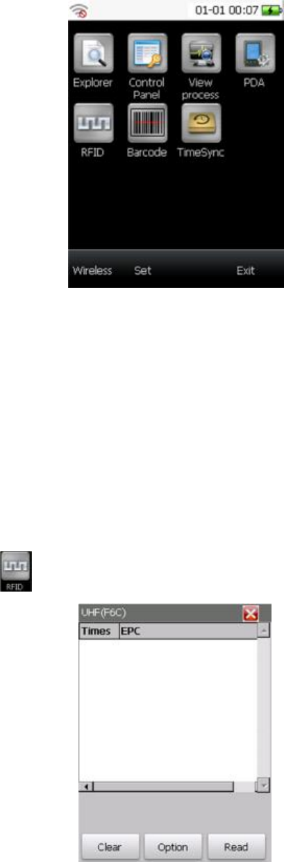
Open the demo software, the main interface will show as below:
Figure 2-1 the main interface
l Explorer: To open the explore in the system
l Control Panel: To open the control panel in the system.
l View process: To open the process viewer in the system.
“PDA”, “RFID”, “Barcode”, “TimeSync” and “Camera” will be described in detail below.
2.2 RFID
RFID module is used for demonstrating the function of radio frequency identification on the RFID handheld
reader, including operations on the tag.
2.2.1 Read tag
Click the button , the RFID interface will come up as below:
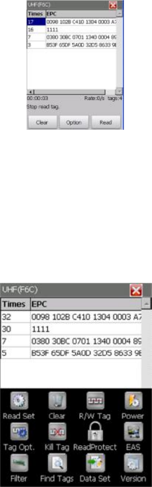
Figure 2-2 RFID interface
l Clear: To clear the scanning results in the table.
l Read: To perform loop reading.
l Option: To set reader parameters and tag operations.
Click the button “Scan” (the button will be transferred to “Stop” after clicking), the reader will perform
loop scanning. That means a tag will be scanned for many times. Then, the data and scanning times of
the tag will be listed in the table. The loop scanning will not be stopped until you click the button “Stop”
(the button will be transferred to “Scan” after clicking). The example is shown as figure 2-3.
Note: scanning can also be performed by pressing the key [SCAN] on the RFID handheld reader.
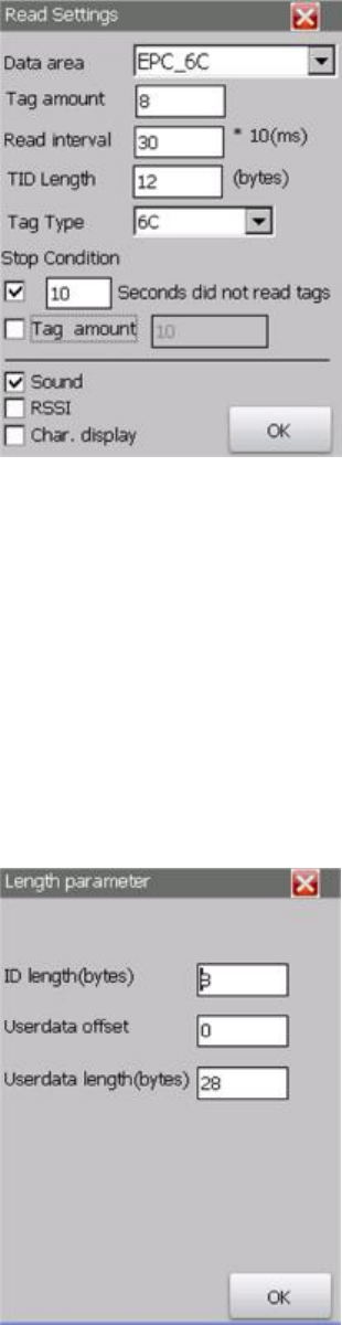
Figure 2-3 read
As shown in the figures above, the scanning state (including reading time, reading rate and tag amount)
will be displayed under the table.
If the data of the last time is not cleared, the current scanning data will be added to the previous data.
In the same word, the scanning times will be added to the value displayed at the last stop instead of 0.
If you would like to count the scanning times from 0, please click “Clear”. Then, the data of the last
scanning will be cleared and could perform a new time of scanning.
The software is set to read TID of tags in default. The reading settings could be changed in “Read set”.
Click “Option”, the interface is shown as figure 2-4.
Figure 2-4 RFID option
The read settings and other settings will be introduced in detail below.
2.2.2 Read Settings
Path: RFID --> Option --> Read Set
Settings: Data area, Tag amount, Read interval, TID Length, Tag Type, RSSI, Sound, Char. display.
The interface is shown as figure 2-5.
Figure 2-5 Read Settings
• Data area:
∘ TID_6C: TID data memory section of 6C tag. The default length is 8 bytes.
∘ EPC_6C: EPC data memory section of 6C tag. The default length is 30 bytes.
∘ EPC_TID_UserData: the data memory sections of 6C tag including EPC, TID and UserData.
The default length of user data memory section is 28 bytes.
∘ EPC_TID_UserData2: the data memory sections of 6C tag including EPC, TID and UserData.
By selecting this option, another interface for setting length parameters will come up. You
can set ID length, UserData offset and UserData length (the length of EPC could not be set,
the length is 30 bytes). The interface is shown as figure 2-6.
Figure 2-6 Length parameter
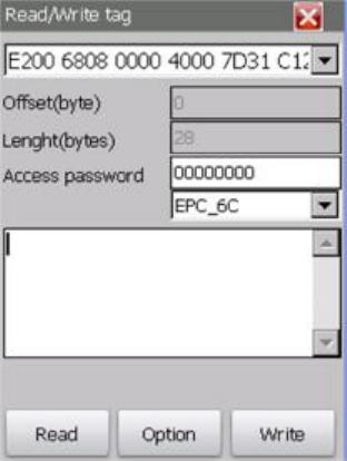
∘ ID length: The length of TID data memory section to be read, measured in bytes.
∘ Userdata offset: The offset address of user data memory section, measured in byte.
∘ Userdata length: The length of user data, measured in bytes.
∘ OK: perform the settings and return to the interface of read settings.
l Tag Amount: to set the max amount of tags covered by the radio signal.
l Read interval: to set the interval of reading tags, measured in 10 milliseconds.
l TID Length: to set the length of TID data memory section that will be read.
l Tag Type: to select the tag type (6C, 6B or 6C/6B).
l Stop Condition:
∘ Read Time: tick to set the reading time period (10 seconds to 300 seconds). If there are no
tags to be read in the period, the reader will stop scanning afterward. Otherwise, scanning
will not be stopped automatically.
∘ Tag amount: tick to set how many tags to be scanned. The reader will stop after the same
numbers of tags have been read.
∘ You can click button “Stop” on the RFID interface to or press the key “SCAN” on the device
to stop reading. You can also press the yellow key on the left side of the device to stop
reading.
l Sound: tick to open the prompt sound.
l RSSI: tick to display RSSI.
l Char. Display: tick to display read data in characters.
l OK: to perform the settings.
2.2.3 Read/Write tag
Path: RFID --> Option --> Read/Write tag
Settings: If the RFID interface has got the read data of tags, you could set the tag reading or writing
settings for each tag on this interface as shown in figure 2-7.
Figure 2-7 Read/Write tag
l Drop-down list: to select a tag to operate.
l Offset: to set the beginning address for operation.
l Length: to set the data length for operation.
l Access password: to enter the correct access password
l Data memory section: to select the data memory section for operation from the drop-down list.
l Text Area: to display or input data.
l Read: to perform read operation.
l Write: to perform write operation.
l Option: click to jump into another interface shown as figure 2-8.
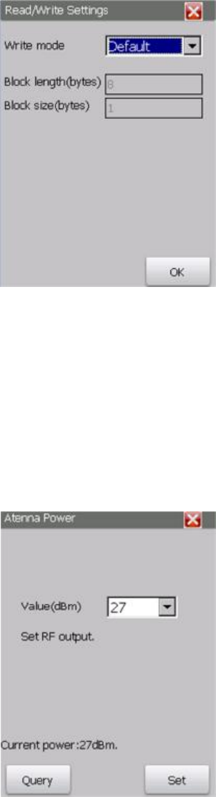
Figure 2-8 Read/Write tag
∘ Write mode: Default, Block write or Block erase.
∘ Block length: the length of block to be operated, measured in bytes. The setting works
providing that the write mode is set to block write or block erase.
∘ Block size: the number of blocks to be operated measured by bytes. The setting only works
if the write mode is block erase.
∘ OK: to perform the settings.
2.2.4 Power
Path: RFID --> Option --> Power
Settings: You could view or set the value of the antenna power on the interface shown as figure 2-9.
Figure 2-9 Antenna Power
l Value: To display or set the value of the antenna power, measured by dBm. The selection is 21,
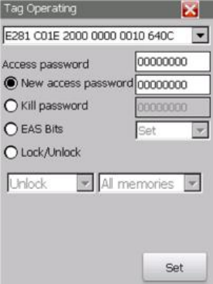
24, 27 or 30dBm.
l Query: to query current antenna power.
l Set: to set new antenna power.
2.2.5 Tag operation
Path: RFID --> Option --> Tag Opt
Settings: If the RFID interface has got the read data of tags, you could set access password, kill password,
EAS Bits, locking or unlocking of memory sections for each tag. The interface is as shown in figure 2-10.
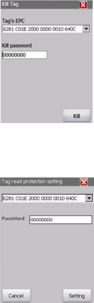
Figure 2-10 Tag Operating
l Drop-down list: to select a tag for operation.
l Access password: to enter the correct current access password.
l New access password: tick to set new access password. Please enter new password in the text
box beside.
l Kill password: tick to set the new Kill password. Please enter new password in the text box
beside.
l EAS Bits: tick to set or cancel EAS Bits.
l Lock/Unlock: tick to perform locking or unlocking operation on the tag.
l Drop-Down list1: to select “Unlock” or “Lock”.
l Drop-Down list2: to select “All Memories”, “TID memory”, “EPC memory”, “User data memory ”,
“Access password” or “Kill password memory”.
l Set: perform the settings. (Note: the default password of the tag is 8 hexadecimal zero, which
may still work after the new access password is set. However, if you lock the data memory
sections using new password, the default access password will not work on the data memory
sections.)
2.2.6 Kill Tag
Path: RFID --> Option --> Kill Tag
Settings: the killed tag will not be available so please be careful on this operation. The EPC and kill
password should be provided when doing this operation, as shown in figure 2-11. Therefore, please
make sure that the EPC of the tag has been read. The read data memory section could be changed
referring to chapter 2.2.2 Read Settings.
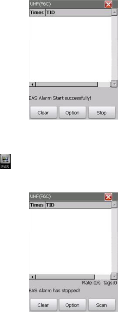
Figure 2-11 Kill tag
l EPC: to select EPC of the tag to be killed.
l Kill Password: to enter the correct kill password.
l Kill: to kill the tag.
2.2.7 Read Protect
Figure 2-12 Tag read protection setting
Drop-down list: to select the tag to be operated.
Password: to set the tag access password.
2.2.8 EAS
EAS is available on tags with NXP tag chips. An EAS flag bit is provided on an EAS tag. After enabling EAS
flag bit, EAS will be on. If tags with enabled EAS flag bits are located in reader field, data of tags with
configured EAS flag bit (alarm information) will be returned. EAS can be disabled by power off operation
instruction.
Figure 2-13 EAS Alarm start
Path: RFID --> Option --> EAS
Click button , the EAS Alarm starts. The opening status of EAS alarm will be displayed on the RFID
interface as shown in figure 2-14. Then, you can click the button “Stop” (the button will transfer to
“Scan” when EAS alarm is stopped) to stop EAS alarm, as shown as figure 2-14.
Figure 2-14 EAS Alarm stop
2.2.9 Filter
Path: RFID --> Option --> Filter
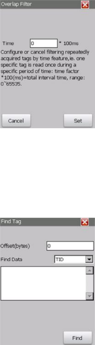
Settings: set or cancel filtering overlap tags by time. In other word, a tag will be read for once in
specified time. The interface is as shown in figure 2-15.
Figure 2-15 Overlap Filter
l Time: set the overlap filtering time, measured by milliseconds. The value is limited from 0 to
65535.
l Cancel: cancel overlap filtering.
l Set: perform the settings.
2.2.10 Find Tags
Path: RFID --> Option --> Find Tags
Settings: set conditions to scan tags that are in these conditions
Figure 2-16 Find Tag
l Offset: to set the offset byte of the tags to be matched.
l Find Data: to set the data memory area of the tags to be matched, “TID” or “EPC”.
l Text area: to enter the key word in the tags to be matched. The text area cannot be empty.
l Find: click to jump back to RFID interface and the scanning result will be displayed in the table.
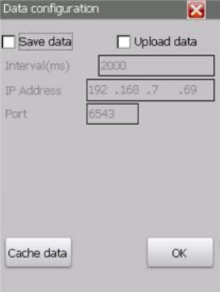
Only the tags matching these conditions can be scanned.
2.2.11 Data Set
Path: RFID --> Option --> Data Set
Settings: save or upload tag data to specified PC. The interface is as shown in figure 2-17.
Figure 2-17 Data configuration
l Save data: tick to perform save data operation. The operation is to save tag data to the file
system of the reader. You can click button “Cache data” to view or process saved data (please
refer to details below).
l Upload data: tick to perform upload operation. The operation is to save data to the PC which is
running data receiving software. Please enter the IP address of that PC and the port monitored
by data receiving software running on that PC (please refer to chapter data receiving software).
l Interval: to set the interval of saving data, measured by milliseconds. The value works providing
that “Sava data” or “Upload data” is ticked.
l IP Address: the IP address of PC which receives uploaded data. The address works providing that
“Upload data” is ticked.
l Port: the port monitored by data receiving software running on the PC which receives uploaded
data. The port works providing that “Upload data” is ticked.
l OK: to perform the settings.
l Cache data: to click to jump into another interface shown as figure 2-18.
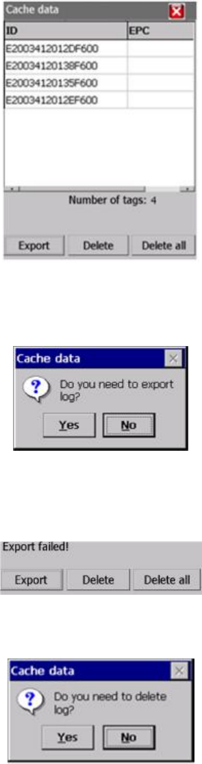
Figure 2-18 Cache data
∘ Export: to export cache data to local file system. A dialog will come up as below.
Click “No” to cancel the operation and return to cache data interface.
Click “Yes” to output data and save to “\InvengoFlash\Demo\Data”. The operation result
will be displayed at the bottom of cache data interface, as shown below.
∘ Delete: to delete selected data. A dialog will come up as below.
Click “No” to cancel the operation and return to cache data interface.
Click “Yes” to delete selected data and return to cache data interface (cache data interface
will be refreshed and the operation result will be displayed).
∘ Delete All: to delete all the cache data (Note: the output file is not deleted). A dialog will
come up as below.
Click “No” to cancel the operation and return to cache data interface.
Click “Yes” to delete selected data and return to cache data interface (cache data interface
will be refreshed and the operation
result will be displayed).
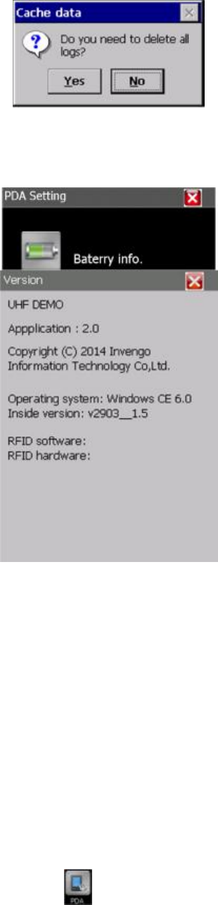
2.2.12 Version
Path: RFID --> Option --> Version
Settings: to display the version of software and hardware.
Figure 2-19 Version
The information displayed is:
l The name of the software
l The version number of software
l The copyright
l The version number of operation system
l The inner version number (to distinguish customization of operation system)
l The version number of RFID software
2.3 PDA settings
PDA settings include viewing power information, brightness adjusting, volume adjusting and version
information, as shown in Figure 2-19. Click , the PDA settings interface is shown as below:
Figure 2-20 PDA Setting
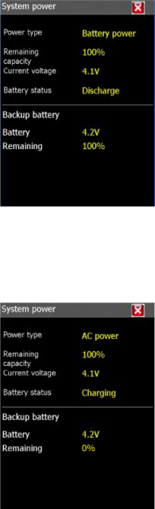
2.3.1 Battery information
Path: PDA settings --> Battery information
Settings: to display power type, remained energy, current voltage and battery status.
There are two ways to supply power for RFID handheld reader as below:
l Battery supplying interface is as shown below:
Figure 2-21 System power-battery power
The battery can be used directly. However, the power is limited so you need to charge the battery
before it runs out.
l Extra power supplying interface is shown below:
Figure 2-22 System power-AC power
You need connect the reader using the power line. That may be a little bit inconvenient but the
power supplying is reliable.
2.3.2 Adjust Backlight
Path: PDA settings --> Adjust backlight
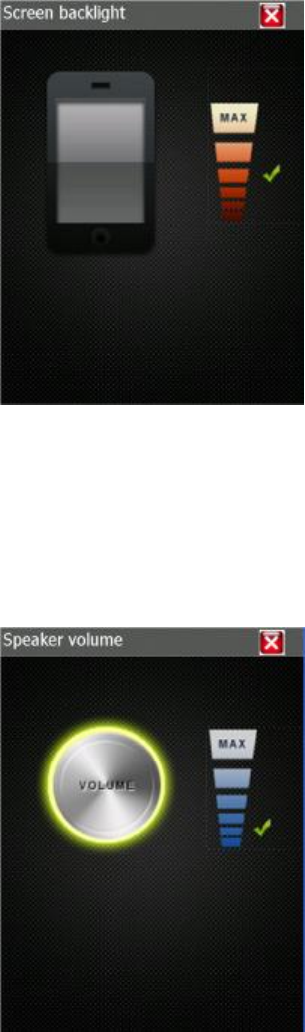
Settings: to adjust brightness of the screen by using the slider, as shown below.
Figure 2-23 Screen backlight
l Upward: the screen will be brighter.
l Downward: the screen will be darker.
l Note: the brightness can also be adjusted by the progress bar.
2.3.3 Adjust Volume
Path: PDA settings --> Adjust Volume
Settings: to adjust the volume using the slider, as shown below.
Figure 2-24 Speaker volume
l Upward: turn up the volume
l Downward: turn down the volume
l Note: the brightness can also be adjusted by the progress bar.
2.3.4 Version information
Path: PDA settings --> Volume adjusting
Settings: to display the version number of software, system and inner version. The interface is shown
below.
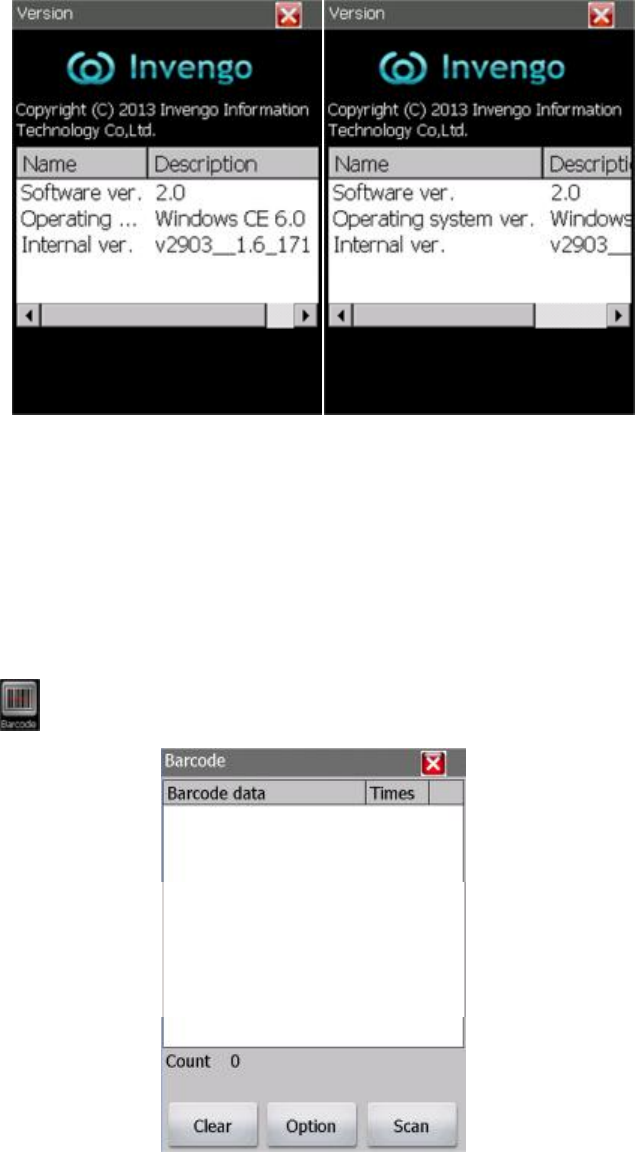
Figure 2-25 Version
l Software version: the version number of software.
l Operation System: the version number of the operation system.
l Inner System: the version number to distinguish customization of operation system.
2.4 Read Barcode
The interface is to display how RFID handheld reader reads barcodes.
2.4.1 Read operation
Click to enter read barcodes interface, as shown below:
Figure 2-26 Barcode
Click button “Read”, barcodes scanning begins. Make the scanner toward to the barcode and the laser
beam horizontally through the barcode. The scanning is set to singe reading in default. In other words,
the reader will stop as soon as the barcode has been read for once. (Note: the single operation can also
be performed by pressing the key [SCAN] on the reader)
The scanning result is shown as below:
You can set loop reading in “Option” referring to chapter “Option” below. Then, the reader can read a
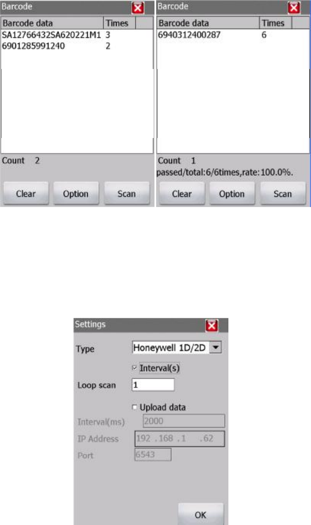
barcode for multiple times. Click button “Stop” to stop scanning. The scanning result will be displayed
as shown below. The scanning state (including amount of tags that have been read, total scanning times,
successful scanning times and reading rate) will be displayed under the table.
Figure 2-27 Barcode-scanning results
Note: if reading barcodes failed, please adjust the position including angle and distance of the reader
towards the barcode.
l Clear: to clear the results.
2.4.2 Option
Click button “Option” on read barcode interface, as shown below:
Figure 2-28 Settings
l Yes: perform the settings.
l Type: to select the type of barcode imager. The available options are Honeywell 1D and Honeywell
1D/2D.
l Loop read: tick the option “Interval(s)” to set loop read.
l Interval: the interval of loop reading, measured by seconds.
l OK: to perform the settings and return to read barcode interface. Then, loop reading begins by
clicking “read” (the button will transfer to “Stop” after clicking). The reading status (reading times,
successful times and failed times) will be displayed at the bottom of the read barcode interface.
Loop reading can be stopped by clicking “stop” (the button will transfer to “read” after clicking).
The reading result is as shown below.
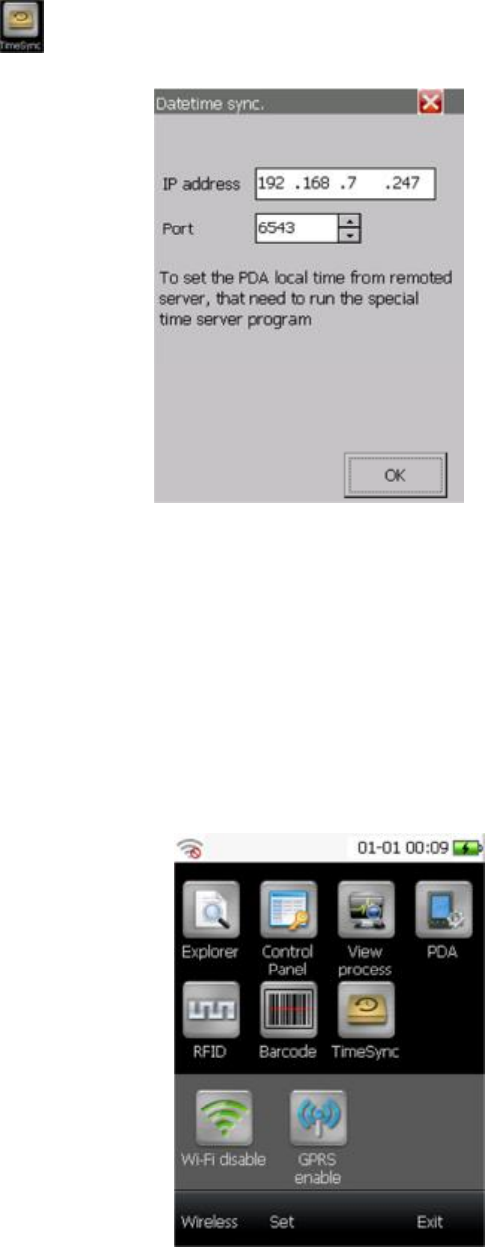
2.5 Synchronization
Click on the main interface to synchronize the time on the RFID handheld reader and the server.
The interface is as shown below.
Figure 2-29 Datetime sync
IP address: the IP address of the server
Port: the port of the server
OK: perform the synchronization operation
The time on RFID reader will be set as same as that on the server, providing that the IP address and port
is correct.
2.6 Other function
2.6.1 Basic operation
Click “wireless”, “Wi-Fi” icon and “GPRS” icon will come up, as shown below.
Figure 2-30 Wireless
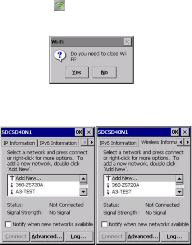
The opening status of Wi-Fi and GPRS will be displayed under the icons. As shown in the picture above, the Wi-Fi
ad GPRS are being closed.
2.6.2 Wi-Fi
Path: “Wi-Fi” on main interface --> Wi-Fi
Providing that Wi-Fi is opening, a confirm message to close Wi-Fi will come up by clicking the icon “Wi-Fi”, as
shown below.
Yes: to close Wi-Fi.
No: not to close Wi-Fi.
Providing that Wi-Fi is being closed, a new interface will come up, as shown below.
Figure 2-31 Wireless information
There are three tabs: IP information, IPv6 information and wireless information. The interface is as shown above.
The IP information tab age will display the IP information. The IPV6 information tab page display the IPv6
information. Please click the tab to view.
Wireless tag page shows all the Wi-Fi signal that has been searched, click the target one and click the button
“connect” to connect to it, as shown below.
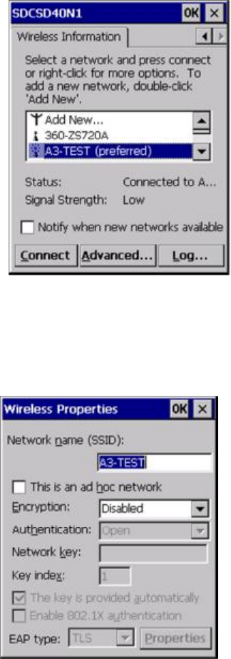
Figure 2-32 connect the wireless
If it is necessary to modify the setting of the target network, please double-click the target name. Then, another
interface will come up, as shown below.
Figure 2-33 Wireless Properties
If the password identifying is not configured, the text box for encryption will display “Forbidden”, otherwise you
need to enter correct password. After modifying the settings, click “OK” to perform the settings and return to
wireless information interface. Then, the reader will be connected to the target network( if the connection is not
made automatically made, please click the target network and click the button “OK” to connect).
2.7 Data receiving software(PC)
Data receiving software is run on the PC, cooperating with the RFID demo software, receiving data sent by
the demo software. Open CommunicationServer.exe on the PC, the interface is shown as below:
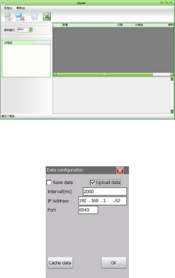
Figure 2-34 Data receiving software
The program will monitor automatically.
Then, please open the demo software on RFID handheld reader, select “RFID--> Option--> data config”, as shown
below.
Figure 2-35 Data configuration
Please see the chapter 2.2.11 Data set for the description of this interface.
Tick “upload data”, enter the IP address of the PC where runs the data receiving software. The port should be the
port monitored by the program on the server (6543 in default). Click “OK” to return to the RFID interface. Then,
click the button “Scan”.
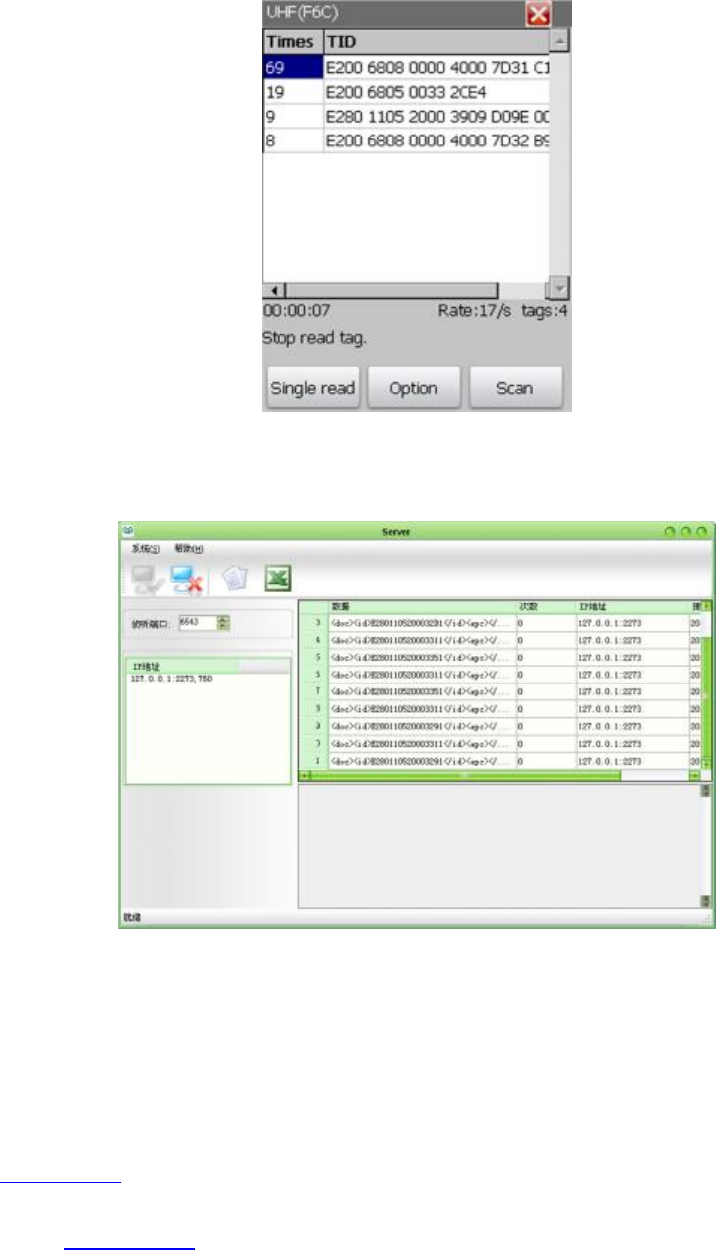
Figure 2-36 RFID interface
By the time the tags are scanned, the demo software will upload the data shown in the table, as shown above.
Then, the data receiving program receives the data as shown below.
3. After sale
3.1 Contact
Invengo Information Technology Co.,Ltd.
3/F, No.T2-B, High-tech Industrial Park South,
Shenzhen 518057,
China
www.invengo.cn
Tel: (86)755 26711633
Fax: (86) 755 26711693
E-mail
:
sales@invengo.cn