Invensys Rail 80319 Gate Tip Tx User Manual August 2005
Invensys Rail Corporation Gate Tip Tx August 2005
UserManual.wiki
>
Invensys Rail
>
80319 User Manual
Users Manual
Navigation menu
Upload a User Manual
Namespaces
Wiki Guide
HTML
PDF
Info
Views
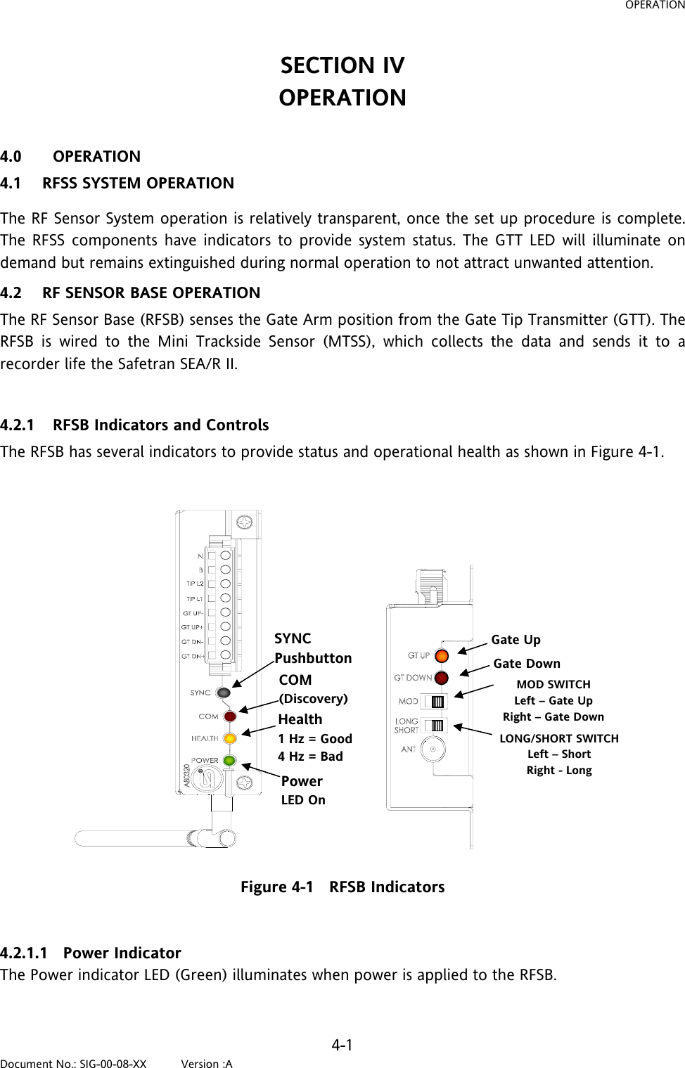
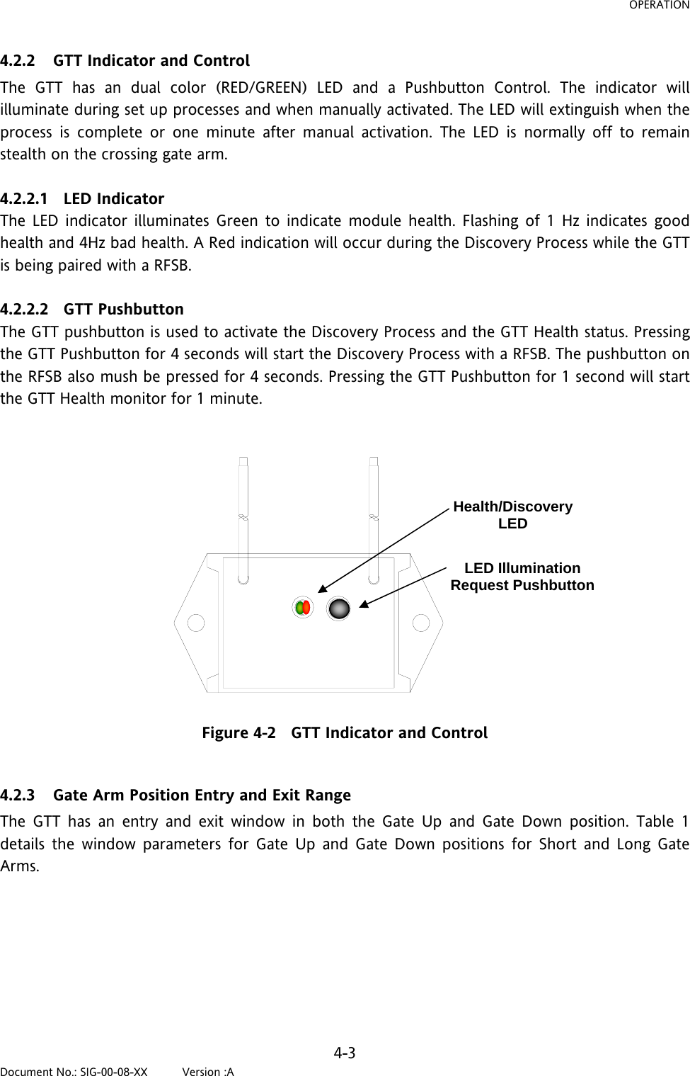
User Manual
Discussion / Help
Navigation