Invensys Rail 80319 Gate Tip Tx User Manual August 2005
Invensys Rail Corporation Gate Tip Tx August 2005
Users Manual

$50.00
PRINTED IN U.S.A.
USER'S GUIDE
RF SENSOR SYSTEM
JULY 2008
DOCUMENT NO. COM-00-08-XX
VERSION A
Safetran Systems Corporation, California Division
10655 7th Street, Cucamonga, California 91730
1-800-793-SAFE
Copyright © 2008 Safetran Systems Corporation, All rights reserved

ii
PROPRIETARY INFORMATION
SAFETRAN SYSTEMS CORPORATION has a proprietary interest in the information contained
herein and, in some instances, has patent rights in the systems and components described. It is
requested that you distribute this information only to those responsible people within your
organization who have an official interest.
This document, or the information disclosed herein, shall not be reproduced or transferred to other
documents or used or disclosed for manufacturing or for any other purpose except as specifically
authorized in writing by SAFETRAN SYSTEMS CORPORATION.
WARRANTY INFORMATION
SAFETRAN SYSTEMS CORPORATION warranty policy is as stated in the current Terms and
Conditions of Sale document. Warranty adjustments will not be allowed for products or
components which have been subjected to abuse, alteration, improper handling or installation, or
which have not been operated in accordance with Seller's instructions. Alteration or removal of any
serial number or identification mark voids the warranty.
SALES AND SERVICE LOCATIONS
Technical assistance and sales information on SAFETRAN products may be obtained at the following
locations:
SAFETRAN SYSTEMS CORPORATION SAFETRAN SYSTEMS CORPORATION
2400 NELSON MILLER PARKWAY CALIFORNIA DIVISION
LOUISVILLE, KENTUCKY 40223 10655 7th STREET
TELEPHONE: (502) 618-8800 CUCAMONGA, CALIFORNIA 91730
FAX: (502) 618-8810 TELEPHONE: (909) 532-5300
SALES & SERVICE: (800) 626-2710 CUSTOMER SERVICE: (800) 793-7233
WEB SITE: http://www.safetran.com TECHNICAL SUPPORT: (800) 793-7233
FAX: (909) 532-5400
FCC RULES COMPLIANCE
This device complies with Part 15 of the FCC rules. Operation is subject to the following two
conditions: (1) This device may not cause harmful interference, and (2) this device must accept
any interference received, including interference that may cause undesired operation.
WARNING TO USERS
The user that changes, or modifications not expressly approved by the part responsible for
compliance could void the user’s authority to operate the equipment.

iii
NOTES, CAUTIONS, AND WARNINGS
Throughout this manual, notes, cautions, and warnings are frequently used to direct the reader’s
attention to specific information. Use of the three terms is defined as follows:
NOTE
Generally used to highlight certain information
relating to the topic under discussion.
CAUTION
REFERS TO PROPER PROCEDURES OR PRACTICES
WHICH IF NOT STRICTLY OBSERVED, COULD RESULT
IN A POTENTIALLY HAZARDOUS SITUATION
AND/OR POSSIBLE DAMAGE TO EQUIPMENT.
CAUTIONS TAKE PRECEDENCE OVER NOTES AND
ALL OTHER INFORMATION, EXCEPT WARNINGS.
WARNING
INDICATES A POTENTIALLY HAZARDOUS
SITUATION WHICH, IF NOT AVOIDED, COULD
RESULT IN DEATH OR SERIOUS INJURY. WARN-
INGS ALWAYS TAKE PRECEDENCE OVER NOTES,
CAUTIONS, AND ALL OTHER INFORMATION.
If there are any questions, contact Safetran Application Engineering.
iv
This Page Intentionally Left Blank

TABLE OF CONTENTS
Section Title Page
PROPRIETARY INFORMATION .................................................................................................... II
WARRANTY INFORMATION ........................................................................................................ II
SALES AND SERVICE LOCATIONS .............................................................................................. II
NOTES, CAUTIONS, AND WARNINGS ..................................................................................... III
TABLE OF CONTENTS.................................................................................................................... V
1.0 INTRODUCTION ........................................................................... 1-1
1.1 SCOPE .............................................................................................................................................1-1
1.2 DEFINITIONS AND ACRONYMS ..............................................................................................1-1
1.3 SYSTEM COMPONENTS .............................................................................................................1-2
1.4 THEORY OF OPERATION ...........................................................................................................1-3
1.5 SYSTEM DESCRIPTION................................................................................................................1-4
1.6 SPECIFICATIONS...........................................................................................................................1-5
1.7 ORDERING INFORMATION.......................................................................................................1-6
2.0 INSTALLATION.............................................................................. 2-1
2.1 GTT INSTALLATION ....................................................................................................................2-1
2.2 RFSB INSTALLATION...................................................................................................................2-3
2.2.1 RFSB Interconnect ........................................................................................................2-4
3.0 SET UP............................................................................................. 3-1
3.1 RFSS SYSTEM SET UP..................................................................................................................3-1
3.2 DISCOVERY PROCESS .................................................................................................................3-1
3.3 RFSB SET UP..................................................................................................................................3-2
3.3.1 MOD Switch ...................................................................................................................3-2
3.3.2 LONG/SHORT SWITCH ................................................................................................3-3
3.3.3 GATE UP REFERENCE ...................................................................................................3-3
4.0 OPERATION ................................................................................... 4-1
4.1 RFSS SYSTEM OPERATION ........................................................................................................4-1
4.2 RF SENSOR BASE OPERATION .................................................................................................4-1
4.2.1 RFSB Indicators and Controls....................................................................................4-1
4.2.1.1 POWER INDICATOR.....................................................................................................4-1
4.2.1.2 HEALTH INDICATOR....................................................................................................4-2
v
Document No.: COM-00-08-XX Version: A

TABLE OF CONTENTS
Section Title Page
4.2.1.3 COM (DISCOVERY) INDICATOR.................................................................................4-2
4.2.1.4 GATE UP INDICATOR ..................................................................................................4-2
4.2.1.5 GATE DOWN INDICATOR ...........................................................................................4-2
4.2.1.6 SYNC PUSHBUTTON ..................................................................................................4-2
4.2.1.7 MOD SWITCH ............................................................................................................4-2
4.2.1.8 LONG/SHORT SWITCH ............................................................................................4-2
4.2.2 GTT Indicator and Control.........................................................................................4-3
4.2.2.1 LED INDICATOR..........................................................................................................4-3
4.2.2.2 GTT PUSHBUTTON .....................................................................................................4-3
4.2.3 Gate Arm Position Entry and Exit Range................................................................4-3
5.0 TROUBLESHOOTING ................................................................... 5-1
5.1 RFSS SYSTEM TROUBLESHOOTING........................................................................................5-1
5.2 OPERATIONAL CHECKS .............................................................................................................5-1
5.2.1 RFSB CHECKS .................................................................................................................5-2
5.2.2 GTT CHECKS ...................................................................................................................5-2
LIST OF FIGURES
Number Title Page
Figure 1-1 Gate Tip Transmitter (GTT) ............................................................................................................1-2
Figure 1-2 RF Sensor Base ...................................................................................................................................1-2
Figure 1-3 System Block Diagram .....................................................................................................................1-3
Figure 1-4 GTT Indicator and Control..............................................................................................................1-4
Figure 1-5 RFSB Indicators and Controls ........................................................................................................1-4
Figure 2-1 Mounting GTT ....................................................................................................................................2-1
Figure 2-2 80319-02 GTT and RECO Light Harness......................................................................................2-2
Figure 2-3 GTT installation with RECO Light..................................................................................................2-2
Figure 2-4 Typical GTT Installation on Gate Arm .........................................................................................2-3
Figure 2-5 Mounting RFSB Component...........................................................................................................2-3
Figure 2-6 RFSB Interconnect ...........................................................................................................................2-4
Figure 3-1 Discovery Process..............................................................................................................................3-1
Figure 3-2 RFSB Set Up ........................................................................................................................................3-2
Figure 3-3 Gate Up Reference............................................................................................................................3-3
Figure 4-1 RFSB Indicators ..................................................................................................................................4-1
vi
Document No.: COM-00-08-XX Version: A

LIST OF FIGURES
Number Title Page
Figure 4-2 GTT Indicator and Control..............................................................................................................4-3
Figure 5-1 RFSB Indicators ..................................................................................................................................5-1
Figure 5-2 GTT Indicators ....................................................................................................................................5-2
LIST OF TABLES
Number Title Page
Table 4-1 Gate Arm Position Entry and Exit Windows...................................................................................4-4
Table 4-2 Gate Arm Position Entry and Exit Windows ................................................................................4-4
Table 5-1 TROUBLESHOOTING CHART.............................................................................................................5-3
vii
Document No.: COM-00-08-XX Version: A
This Page Intentionally Left Blank
viii
Document No.: COM-00-08-XX Version: A
INTRODUCTION
SECTION I
INTRODUCTION
1.0 INTRODUCTION
1.1 SCOPE
This manual describes the installation and operation of the Safetran RF Sensor System
consisting of an RF Sensor Base (RFSB) and a Gate Tip Transmitter (GTT).
1.2 DEFINITIONS AND ACRONYMS
RF Sensor System (RFSS) – General term for a base and sensor combination. For this
specification, the sensor is the GTT and the base (RFSB) monitors the gate arm position and
reports “down” and “up” events to the MTSS
RF Sensor Base (RFSB) – A device that receives the sensor information transmissions and may
determine events and report to a monitoring system.
Gate Tip Transmitter (GTT) – A device that attaches near the end of a crossing gate arm and
transmits position information. This tip sensor uses a low power RF radio to communicate with a
base device.
Industrial, Scientific and Medical Band (ISM) – Radio frequencies available for use by
unlicensed devices governed by Part 18 of the FCC rules. The RFSS uses a low power radio
communicating on several frequencies in the 902-928 MHz band.
Safetran Mini Trackside Sensor (MTSS) – A device for collecting various sensor data and
reporting to a centralized device.
Up/Vertical/Clear – Position of a Gate Arm that allows traffic to cross a railway. Due to
overhead clearance, many gate arms are not vertical when they are stopped and locked in their
raised position. The “Up” condition is indicated when the gate arm is within 10º of the established
reference position.
Down/Horizontal/Level – Position of a Gate Arm that prevents traffic from crossing a railway.
The “Down” condition is indicated when the gate arm is within 3º of the established reference
position.
Beacon – A signal that is broadcast for synchronization or notification. For the RFSS, the RF
Sensor Base broadcasts a beacon packet to indicate the start of a communication period on a
frequency. The beacon also contains a list of the successive frequencies that the RFSB will use.
Discovery – Procedure used by a base and a tip to uniquely distinguish each other and exchange
configuration information. After a successful Discovery, the base and tip will remain “paired” until
the next Discovery.
1-1
Document No.: SIG-00-08-XX Version: A
INTRODUCTION
1.3 SYSTEM COMPONENTS
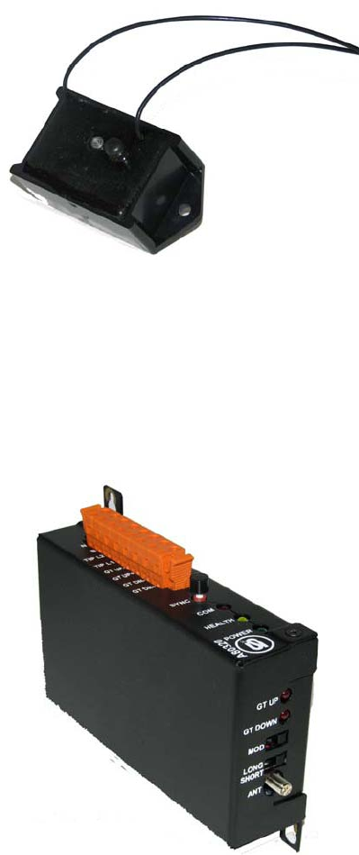
The RFSS has two components: the GTT, as shown in Figure 1-1, which gathers and transmits gate
arm position information
Figure 1-1 Gate Tip Transmitter (GTT)
The RFSB, as shown in Figure 1-2, which receives and analyzes the position information and
provides the output signals to the recording equipment.
Figure 1-2 RF Sensor Base
Both components use PC-boards which have a microcontroller and radio; in addition, the GTT has
an accelerometer.
1-2
Document No.: SIG-00-08-XX Version :A
INTRODUCTION
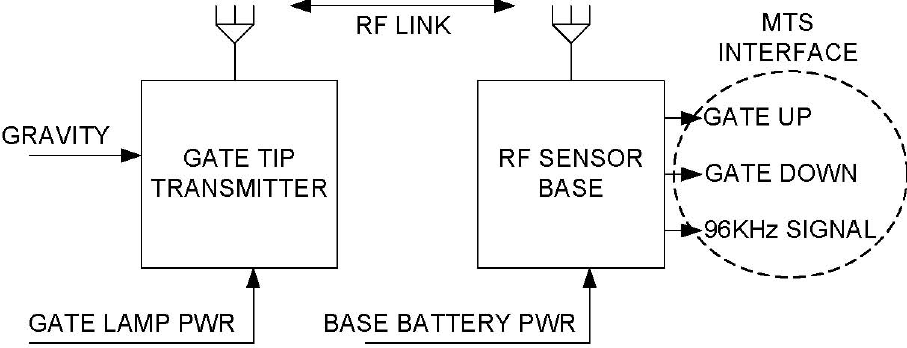
1.4 THEORY OF OPERATION
The RFSS uses an RF Sensor Base (RFSB) and a Gate Tip Transmitter (GTT) to sense the position of
the grade crossing barrier arm and provide event signals to reporting equipment (MTSS).
Figure 1-3 System Block Diagram
The GTT continually senses orientation and movement of the gate arm using an accelerometer
and transmits the 3-axis acceleration values to the RFSB using a low power radio. The RFSB
receives the radio packets from the GTT, analyzes the data and sets the output signals to indicate
the position of the gate arm.
The RF Sensor System interface to the reporting equipment (MTSS) is provided by the RF Sensor
Base. The Gate Tip Transmitter communicates with the RFSB; but has no direct interface to the
MTSS.
For compatibility with the existing 80282 Gate Tip Sensor, the RFSB provides a 96 KHz signal to
the MTSS to indicate Gate-Down. In addition to the current 96 KHz signal, the RFSB provides
independent Gate-Down and Gate-Up position indications (both LED and digital output) and
allows switching the 96 KHz carrier to be presented on either Gate-Down or Gate-Up condition.
Note that the digital signals are independent; Gate Down and Gate Up are asserted or de-asserted
independently. Since the position of the gate arm is actually down, up or somewhere in between,
the indications are Down-asserted, Up-asserted or both de-asserted. While Down and Up are
exclusive events, they are not opposites.
The System devices (RFSB and GTT) rely on a local power source, but they do not require signal
wiring or use the power wiring for signaling. The devices use low power radios for wireless
communication.
1-3
Document No.: SIG-00-08-XX Version: A
INTRODUCTION
1.5 SYSTEM DESCRIPTION
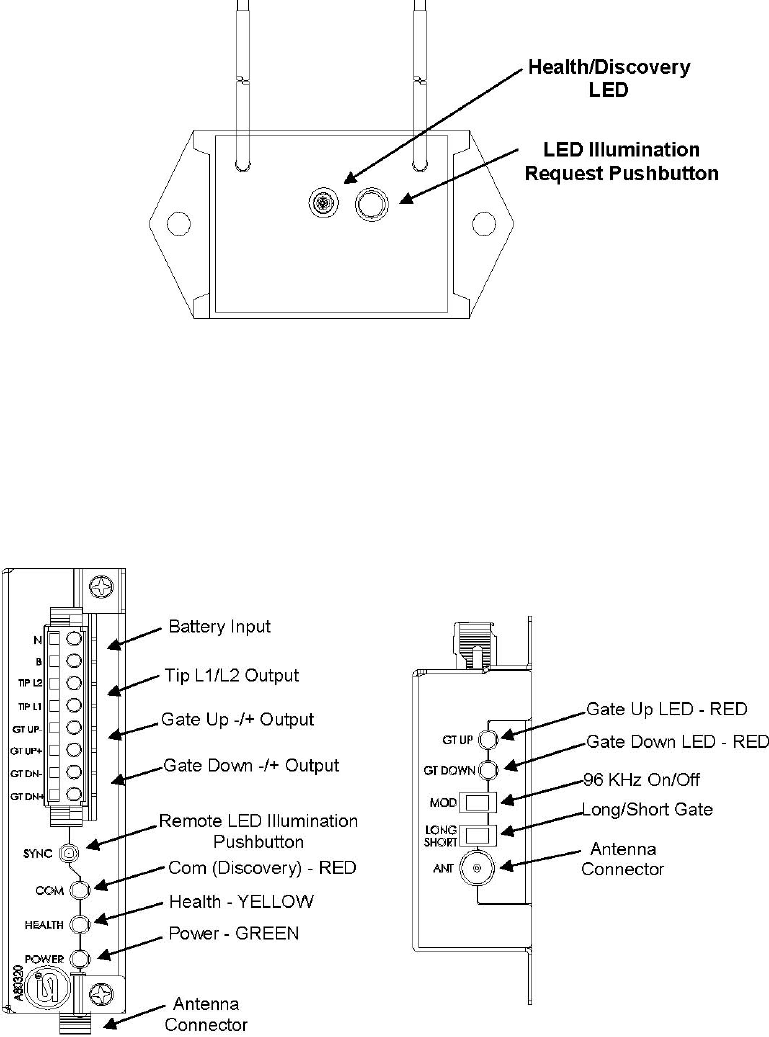
The GTT has a single Green/Red LED that is illuminated on request to indicate Health (Green) or
Discovery (Red). There is a single pushbutton to request LED illumination or a Discovery
sequence. The GTT is in an exposed location (on the gate arm), so the LED is normally off to
avoid drawing attention to the device.
Figure 1-4 GTT Indicator and Control
The RFSB has LEDs to indicate POWER, HEALTH, DOWN position, UP position and COM
(Discovery); these LEDs are illuminated whenever appropriate. The RFSB has a SYNC pushbutton
that is used to request Remote LED illumination, establish Gate-Up reference, or Discovery
sequence. The RFSB has two configuration switches: LONG/SHORT for different length gate arms
and MOD to activate the 96 KHz carrier signal (Gate-Down or Gate-Up).
Figure 1-5 RFSB Indicators and Controls
1-4
Document No.: SIG-00-08-XX Version :A
INTRODUCTION
1.6 SPECIFICATIONS
Gate Tip Transceiver
Input Voltage 9.0 – 20.0 VAC - VDC (13.2 V Nominal) Any Polarity
Input Current 0.2A @ Nominal Voltage
Environmental:
Temperature: -40 F - +160 F (-40 C - +71 C)
Humidity: Hermetically Sealed
Dimensions:
Length: 3.0 inches (7.6 cm)
Width: 1.5 inches (3.8 cm)
Depth: 1.625 inches (4.1 cm)
Weight:: 2 ounces (56.7 g)
FCC ID: LTY80319
IC: 2347A-80319
FCC CFR Part 15.247 and 15.109 Class B compliant
Frequency Range: 902 MHz – 928 MHz ISM Band
Number of Channels: 10
Channel Separation: 325 KHz
RF Output Power: +10 dBm
Modulation: FSK, OOK, MSK, GFSK
Differential Load Impedance: 86.5 + j43 Ω
FSK Data Rate: 500 kbps Maximum
RSSI Output: Digital
Receiver Sensitivity (FSK): -94 dBm
Spurious Emissions: -57 dBm
Antenna Connection Differential
RF Sensor Base
Input Voltage 8.0 – 34.5 VDC (13.2 V Nominal)
Input Current 0.2A @ Nominal Voltage
Environmental:
Temperature: -40 F - +160 F (-40 C - +71 C)
Humidity: 95% non-condensing
Dimensions:
Length: 3.50 inches (8.9 cm)
Width: 6.00 inches (15.2 cm)
Depth: 1.15 inches (2.9 cm)
Weight:: 1.25 lbs (567 g)
FCC ID: LTY80319
IC: 2347A-80319
1-5
Document No.: SIG-00-08-XX Version: A

INTRODUCTION
FCC CFR Part 15.247 and 15.109 Class B compliant
Frequency Range: 902 MHz – 928 MHz ISM Band
Number of Channels: 10
Channel Separation: 325 KHz
RF Output Power: +10 dBm
Modulation: FSK, OOK, MSK, GFSK
Differential Load Impedance: 86.5 + j43 Ω
FSK Data Rate: 500 kbps Maximum
RSSI Output: Digital
Receiver Sensitivity (FSK): -111 dBm
Spurious Emissions: -57 dBm
Antenna Connection: RP - SMA
Antenna: ½ Wave Center-fed Dipole
Frequencies Used: 903.4 – 903.6 MHz
905.8 – 906.0 MHz
908.2 – 908.4 MHz
910.6 – 910.8 MHz
913.0 – 913.2 MHz
915.4 – 915.6 MHz
917.8 – 918.0 MHz
920.2 – 920.4 MHz
922.6 – 922.8 MHz
925.0 – 925.2 MHz
1.7 ORDERING INFORMATION
CONFIGURATION CHART
8000-80314-00X
X
GATE TIP TRANSMITTER ASSEMBLY
MOUNTING PLATE
1 = 80319-01 (ITEM 2)
2 = 80319-02 (ITEM 3) W/RECO
0 = NONE
1 = 074035-8-1 (ITEM 4) S-60
2 = 074038-8 (ITEM 5) S-40
1-6
Document No.: SIG-00-08-XX Version :A
INSTALLATION
SECTION II
INSTALLATION
2.0 INSTALLATION
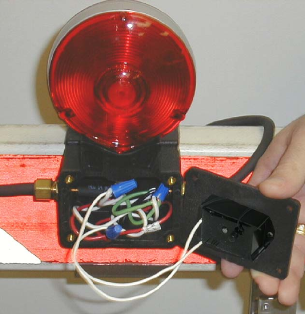
2.1 GTT INSTALLATION
The GTT installs in the lamp assembly on the gate arm. Wires are attached in parallel to existing
Tip Light power wires using wire nuts. The GTT is mounted inside the cover of the Tip Light
junction box using two #10 self tapping sheet metal screws included with the unit. The GTT should
be mounted as near to the end of the gate as possible. The long surface is parallel to the edge of
the gate arm.
Figure 2-1 Mounting GTT
2-1
Document No.: SIG-00-08-XX Version:A
INSTALLATION
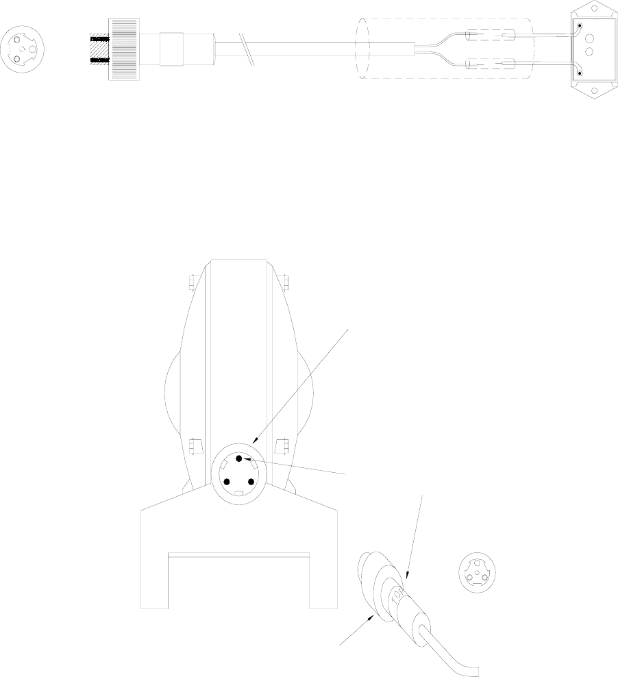
Crossing gates using the Reco Tip Lights will require the use of the 80319-02 GTT shown in Figure
2-1, which includes a cable and plug.
Figure 2-2 80319-02 GTT and RECO Light Harness
The GTT RECO Light Harness connects to the Exit Connector on the Tip Light. as shown in Figure
2-3.
TOP
TOP PIN IN LAMP HOUSING CONNECTOR
MUST BE ALIGNED WITH THE WORD "TOP"
MARKED ON GATE-TIP SENSOR CABLE PLUG
TIP LIGHT
EXIT CONNECTOR ON
TIP LIGHT
FRONT VIEW
(SHOWS MISSING TOP
CONTACT)
(TOP TERMINAL DOES NOT HAVE A METAL
CONTACT INSERTED INTO THE MOLDED
CONNECTOR)
Figure 2-3 GTT installation with RECO Light
2-2
Document No.: SIG-00-08-XX Version:A
INSTALLATION
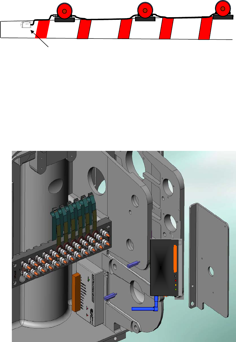
The GTT is mounted on the tip of the gate arm using the two #10 self tapping screws included
with the GTT. A typical installation is shown in Figure 2-4.
Gate Tip
Transmitter
Figure 2-4 Typical GTT Installation on Gate Arm
2.2 RFSB INSTALLATION
The RFSB module installs inside the crossing gear box. A mounting plate is provided to mount the
RFSB inside the gear box compartment as shown in Figure 2-5. Arrange the swivel antenna away
from any gears or moving parts.
Figure 2-5 Mounting RFSB Component
2-3
Document No.: SIG-00-08-XX Version:A
SET UP PROCEDURE
SECTION III
SET UP PROCEDURE
3.0 SET UP
3.1 RFSS SYSTEM SET UP
The RF Sensor System set up procedure a simple operation. The procedure requires the crossing
be powered up and the crossing gate in the down position. The appropriate measures will be
required to secure vehicular traffic as well as pedestrian and worker safety.
WARNING
SET UP OF THE RF SENSOR SYSTEM REQUIRES
THE CROSSING BE POWERED AND THE GATE IN
THE DOWN POSITION. DELOY THE APPRORIATE
RAILROAD SAFETY PROCEDURES TO SECURE
VEHICULAR TRAFFIC AS WELL AS PEDESTRIAN
AND WORKER SAFETY.
3.2 DISCOVERY PROCESS
It is necessary to pair a GTT and RFSB together using the Discovery Process. Only one GTT and
RFSB can be powered during the Discovery Process.
Pushbutton
At least 4 seconds
Com (Discovery) - RED
Power - GREEN
Discovery LED
(RED)
Pushbutton
At least 4 seconds
Figure 3-1 Discovery Process
3-1
Document No.: SIG-00-08-XX Version :A
OPERATION
Perform the following procedure to pair the GTT and RFSB:
1.) Verify power is applied to the RFSB and the Power LED is illuminated.
2.) Verify Crossing Gate is powered and gate lamp power is on.
3.) Lower Crossing Gate
4.) Press Pushbutton of GTT for one second and verify LED is illuminated GREEN.
5.) Press GTT Pushbutton and hold for at least 4 seconds and verify LED is RED.
6.) Press RFSB Pushbutton and verify COM (Discovery) LED is illuminated solid.
7.) The GTT LED and RFSB COM LED will be lit during the Discovery Process.
8.) When GTT and RFSB LEDs extinguish the Discovery Process is complete.
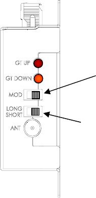
3.3 RFSB SET UP
The RFSB has two slide switch adjustments to configure the unit to the crossing gate as shown in
Figure 3-2.
MOD SWITCH
Left – Gate Up
Right – Gate Down
LONG/SHORT SWITCH
Left – Short
Right - Long
Figure 3-2 RFSB Set Up
3.3.1 MOD Switch
The MOD switch on the RFSB selects the gate arm position that will activate the 96 KHz carrier.
With the switch set to the left (towards the silkscreen) the output is set for activation in the gate
arm up position. With the switch to the right (away from the silkscreen) the activation will be
when the gate arm is down. For compatibility to the 80282 Gate Tip Sensor, the switch should be
set to provide carrier when the gate arm is down.
3-2
Document No.: SIG-00-08-XX Version: A
SET UP PROCEDURE
3.3.2 LONG/SHORT SWITCH
The Long/Short Switch on the RFSB configures the Gate Arm length. Short Gates are less than 25
feet in length. Long Gates are 25 feet or longer in length. Set the switch to the left for Short gate
arms and to the right for Long gate arms.
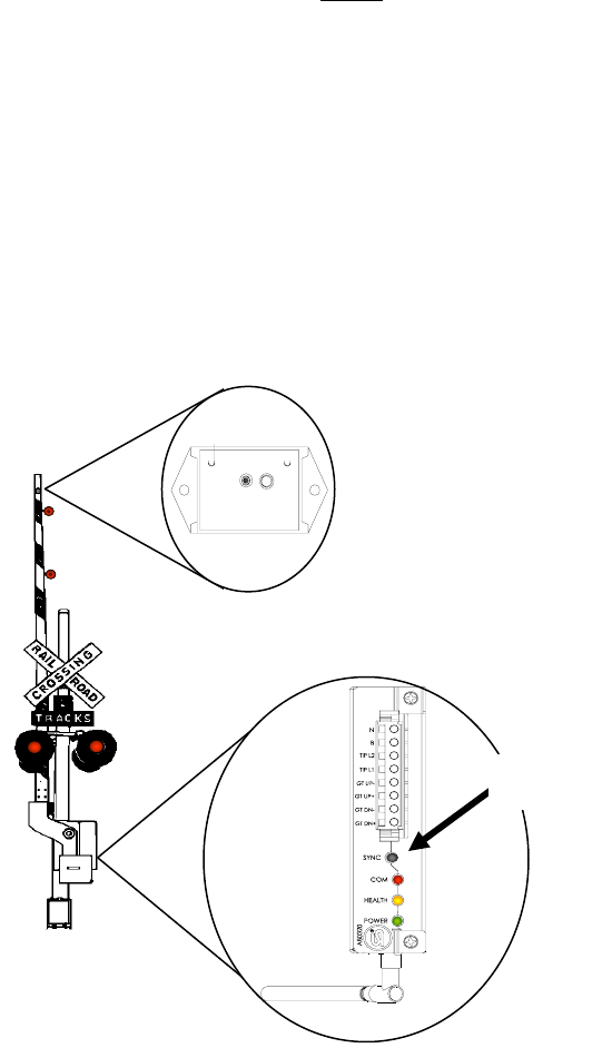
3.3.3 GATE UP REFERENCE
To establish a “Gate UP” reference in the RFSB, perform the following procedure:
NOTE
To perform the “Gate Up” reference procedure,
power must be applied to the GTT with the Gate
Arm in the “Up” position.
1.) With the Gate Arm Up and power applied to the GTT, press the SYNC pushbutton on
the RFSB three (3) times.
2.) Verify the RFSB COM LED is illuminated.
3.) When the RFSB COM LED extinguishes, the reference procedure is completed.
4.) Restore normal signal operation.
Push SYNC
Button 3
Figure 3-3 Gate Up Reference
3-3
Document No.: SIG-00-08-XX Version :A
OPERATION
This Page Intentionally Left Blank
3-4
Document No.: SIG-00-08-XX Version: A
OPERATION
SECTION IV
OPERATION
4.0 OPERATION
4.1 RFSS SYSTEM OPERATION
The RF Sensor System operation is relatively transparent, once the set up procedure is complete.
The RFSS components have indicators to provide system status. The GTT LED will illuminate on
demand but remains extinguished during normal operation to not attract unwanted attention.
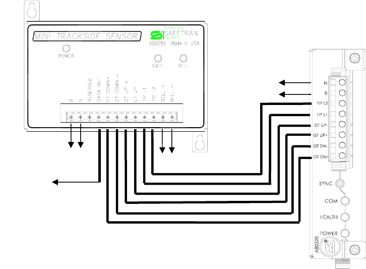
4.2 RF SENSOR BASE OPERATION
The RF Sensor Base (RFSB) senses the Gate Arm position from the Gate Tip Transmitter (GTT). The
RFSB is wired to the Mini Trackside Sensor (MTSS), which collects the data and sends it to a
recorder life the Safetran SEA/R II.
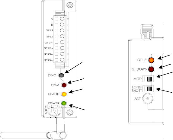
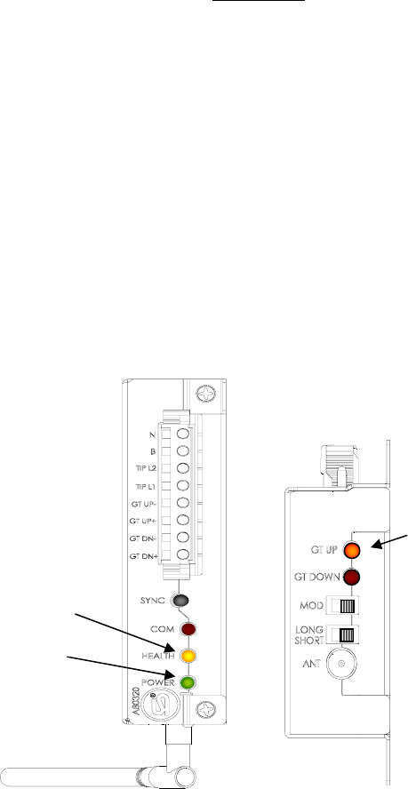
4.2.1 RFSB Indicators and Controls
The RFSB has several indicators to provide status and operational health as shown in Figure 4-1.
Gate Up
LONG/SHORT SWITCH
Left – Short
Right - Long
MOD SWITCH
Left – Gate Up
Right – Gate Down
Gate Down
Health
1 Hz = Good
4 Hz = Bad
Powe
r
LED On
COM
(Discovery)
SYNC
Pushbutton
Figure 4-1 RFSB Indicators
4.2.1.1 Power Indicator
The Power indicator LED (Green) illuminates when power is applied to the RFSB.
4-1
Document No.: SIG-00-08-XX Version :A
OPERATION
4.2.1.2 Health Indicator
The Health indicator (Amber) is illuminated when power is applied to the RFSB and provides the
Health status of the module. A 1 Hz flash rate indicates Good health. A 4 Hz flash rate indicates
Bad Health and the module requires service.
4.2.1.3 COM (Discovery) Indicator
The COM indicator (Red) illuminates during the Discovery operation while establishing a link with
the GTT. The COM indicator also illuminates during the Gate Up Reference operation as the RFSB
communicates with the GTT and records the Gate Up information.
4.2.1.4 Gate Up Indicator
The Gate Up Indicator (Red) illuminates when the crossing gate arm is in the up position. In most
installations, the GTT will be powered from the tip light power and only active while the gate
lamps are on. Once the gate is in the up position and the power to the lamps and the GTT is
removed, the Gate Up LED will extinguish until the GTT is repowered and the gate becomes active.
Supplying continuous power to the GTT will provide an indication at all times.
4.2.1.5 Gate Down Indicator
The Gate Down indicator (Red) illuminates when the gate arm is in the down position.
4.2.1.6 SYNC Pushbutton
The SYNC Pushbutton has three modes. Each mode uses a different sequence to initiate the
function.
4.2.1.6.1 SYNC Pushbutton Discovery Mode
Pressing the SYNC pushbutton for 4 seconds or longer will start the Discovery Process. The
Discovery process pairs the RFSB with a GTT as detailed in the Set Up Section.
4.2.1.6.2 SYNC Pushbutton Gate Up Reference Mode
Pressing the SYNC pushbutton 3 times with the crossing gate arm in the Up position, will establish
the Gate Up Reference for the RFSB. This reference is sent from the GTT to the RFSB and stored
as the Gate Up position.
4.2.1.6.3 SYNC Pushbutton GTT Health Mode
Pressing the SYNC pushbutton 1 time activates the GTT LED in the Health monitor mode for one
minute.
4.2.1.7 MOD Switch
The MOD Switch sets the gate position that will activate the 96 KHz carrier. Left towards the
silkscreen is Gate Up, and Right away from the silkscreen is Gate Down.
4.2.1.8 LONG/SHORT Switch
The LONG/SHORT Switch is used set the system for Long (25 ft or longer) or Short (24 ft or less)
crossing gate arms.
4-2
Document No.: SIG-00-08-XX Version: A

OPERATION
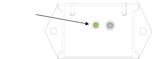
4.2.2 GTT Indicator and Control
The GTT has an dual color (RED/GREEN) LED and a Pushbutton Control. The indicator will
illuminate during set up processes and when manually activated. The LED will extinguish when the
process is complete or one minute after manual activation. The LED is normally off to remain
stealth on the crossing gate arm.
4.2.2.1 LED Indicator
The LED indicator illuminates Green to indicate module health. Flashing of 1 Hz indicates good
health and 4Hz bad health. A Red indication will occur during the Discovery Process while the GTT
is being paired with a RFSB.
4.2.2.2 GTT Pushbutton
The GTT pushbutton is used to activate the Discovery Process and the GTT Health status. Pressing
the GTT Pushbutton for 4 seconds will start the Discovery Process with a RFSB. The pushbutton on
the RFSB also mush be pressed for 4 seconds. Pressing the GTT Pushbutton for 1 second will start
the GTT Health monitor for 1 minute.
Health/Discovery
LED
LED Illumination
Request Pushbutton
Figure 4-2 GTT Indicator and Control
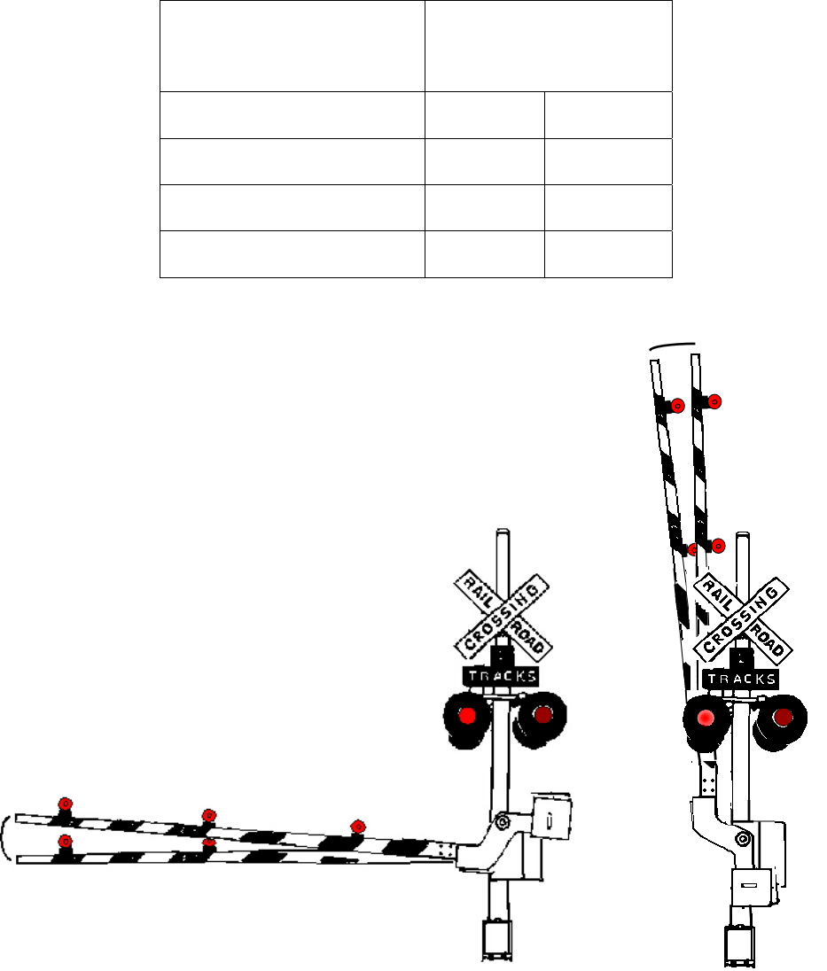
4.2.3 Gate Arm Position Entry and Exit Range
The GTT has an entry and exit window in both the Gate Up and Gate Down position. Table 1
details the window parameters for Gate Up and Gate Down positions for Short and Long Gate
Arms.
4-3
Document No.: SIG-00-08-XX Version :A
OPERATION
Table 4-1 Gate Arm Position Entry and Exit Windows
Switch
SHORT LONG
Down-Entry (GT DN On) 5º 3º
Down-Exit (GT DOWN Off) 8º 4º
Up-Exit (GT UP Off) 8º 4º
Up-Entry (GT UP On) 5º 3º
Table 4-2 Gate Arm Position Entry and Exit Windows
4-4
Document No.: SIG-00-08-XX Version: A
TROUBLESHOOTING
SECTION V
TROUBLESHOOTING
5.0 TROUBLESHOOTING
5.1 RFSS SYSTEM TROUBLESHOOTING
The RF Sensor System operation is relatively transparent. However, should a problem occur, the
following troubleshooting procedures will aid in identifying the source of the problem.
WARNING
SERVICING THE RF SENSOR SYSTEM REQUIRES
THE CROSSING BE POWERED AND THE GATE IN
THE DOWN POSITION. DELOY THE APPRORIATE
RAILROAD SAFETY PROCEDURES TO SECURE
VEHICULAR TRAFFIC AS WELL AS PEDESTRIAN
AND WORKER SAFETY.
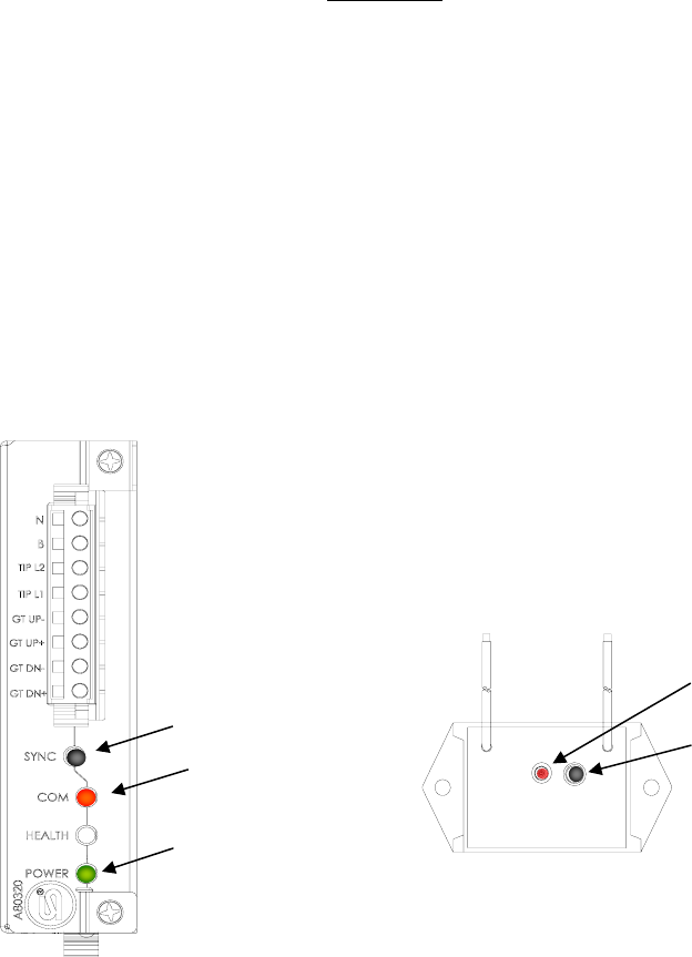
5.2 OPERATIONAL CHECKS
Simple checks can be made to verify the system operation. Reviewing the indicator LEDs will
provide the system’s operational status.
Gate Up
Health
1 Hz = Good
4 Hz = Bad
Powe
r
LED On
Figure 5-1 RFSB Indicators
5-1
Document No.: SIG-00-08-XX Version :A
TROUBLESHOOTING
5.2.1 RFSB CHECKS
Perform the following checks on the RFSB module:
1.) Verify the POWER LED is illuminated.
2.) Check the HEALTH LED. 1 Hz = GOOD, 4 Hz = Bad
3.) Check the GT UP (Gate Up) LED is illuminated (assuming the gate arm is up).
4.) Verify all wiring is properly terminated and secure.
5.) Verify the MOD and LONG/SHORT switches are in their proper positions.
6.) Verify antenna is securely mounted.
5.2.2 GTT CHECKS
Perform the following checks on the GTT module:
HEALTH
1 Hz = Good
4 Hz = Bad
Figure 5-2 GTT Indicators
1.) Press the SYNC pushbutton on the RFSB module once and check the LED indicator on the
GTT module. A 1 Hz flash rate indicates GOOD health a 4 Hz flash rate indicates bad
health.
2.) If the LED is NOT flashing, press the pushbutton on the GTT once. If the LED is flashing
verify is the flash rate is 1 Hz indicating GOOD health or 4 Hz BAD health.
3.) If no indication is observed on the GTT LED, verify power is available to the GTT module.
4.) If GTT LED did NOT illuminate after pressing the RFSB pushbutton and DID illuminate after
pressing the GTT pushbutton, perform the Discovery Procedure and verify the GTT and
RFSB are communicating as a pair.
5-2
Document No.: SIG-00-08-XX Version: A

TROUBLESHOOTING
Table 5-1 TROUBLESHOOTING CHART
GTT TROUBLESHOOTING
LED Indicator will not illuminate Verify power is available.
Verify power is within specification, 9 – 20 VAC or VDC
Verify power wires are not cut or broken
Replace GTT Module
LED Indicates BAD Health Replace GTT Module
LED will not illuminate when RFSB
module pushbutton is pressed once
Perform Discovery Procedure
Verify RFSB module is operational
RFSB TROUBLESHOOTING
Power LED not illuminated Verify power is available
Verify power is within specification, 9 – 20 VAC or VDC
Verify power wires are not cut or broken
Replace RFSB Module
Health LED indicates BAD Health Replace RFSB Module
RFSB Module will not communicate
with GTT Module
Verify GTT Module is operational
Perform Discovery Procedure
Verify antenna is securely fastened
RFSB not communicating with MTSS Verify RFSB is in good health
Verify Cage Clamp connector is secure
Verify wiring is properly terminated and secure
RF Sensor System Troubleshooting
Gate Up LED not illuminated when
Gate Arm is Up
Perform Gate Up Reference Procedure
Verify GTT is mounted properly
Verify MOD Switch is set for proper Gate Length
Verify GTT is good health
5-3
Document No.: SIG-00-08-XX Version :A
TROUBLESHOOTING
This Page Intentionally Left Blank
5-4
Document No.: SIG-00-08-XX Version: A