Invensys Rail 9710-PS009900 MCP CAB RADIO User Manual Cab Radio COM 00 09 08PDF
Invensys Rail Corporation MCP CAB RADIO Cab Radio COM 00 09 08PDF
UserManual.wiki
>
Invensys Rail
>
9710 PS009900 User Manual
Users Manual
Navigation menu
Upload a User Manual
Namespaces
Wiki Guide
HTML
PDF
Info
Views
User Manual
Discussion / Help
Navigation
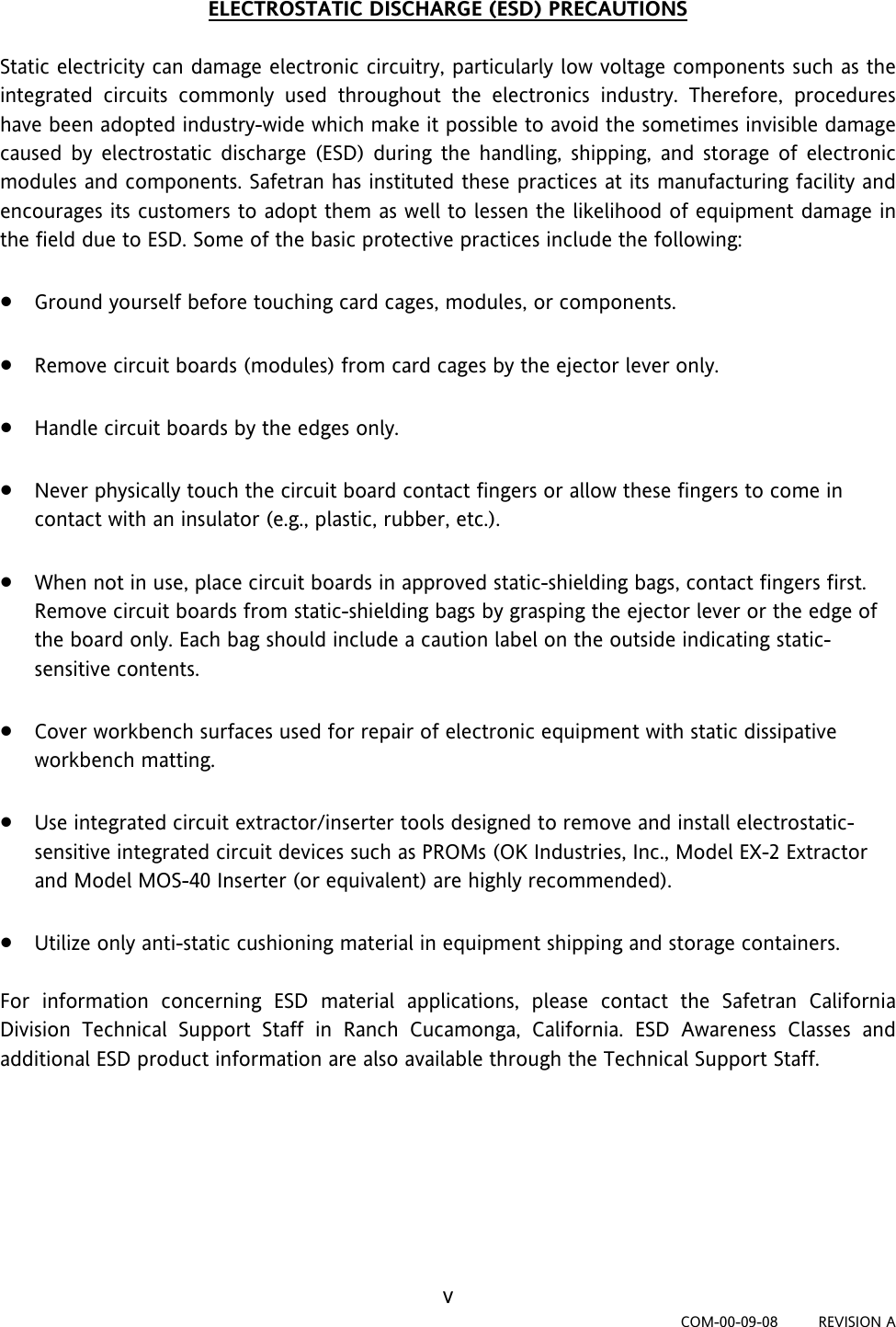
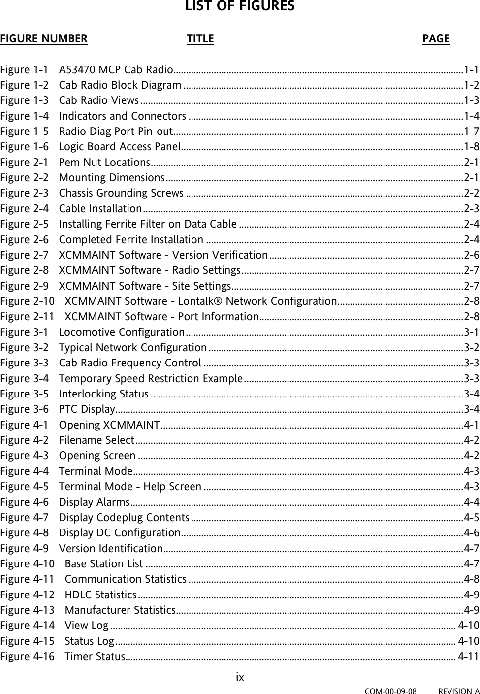


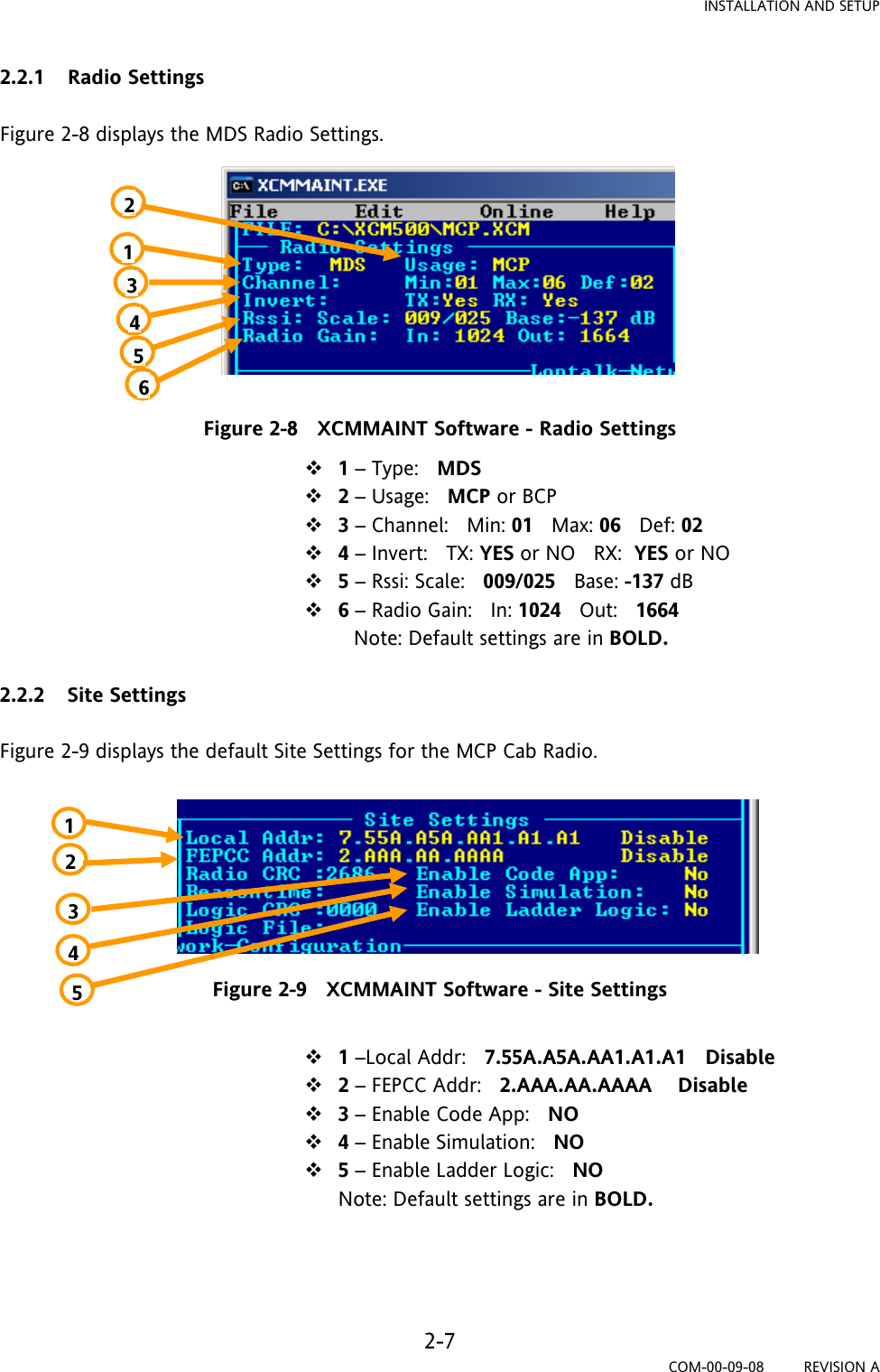
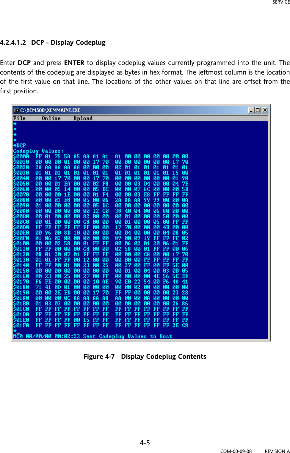
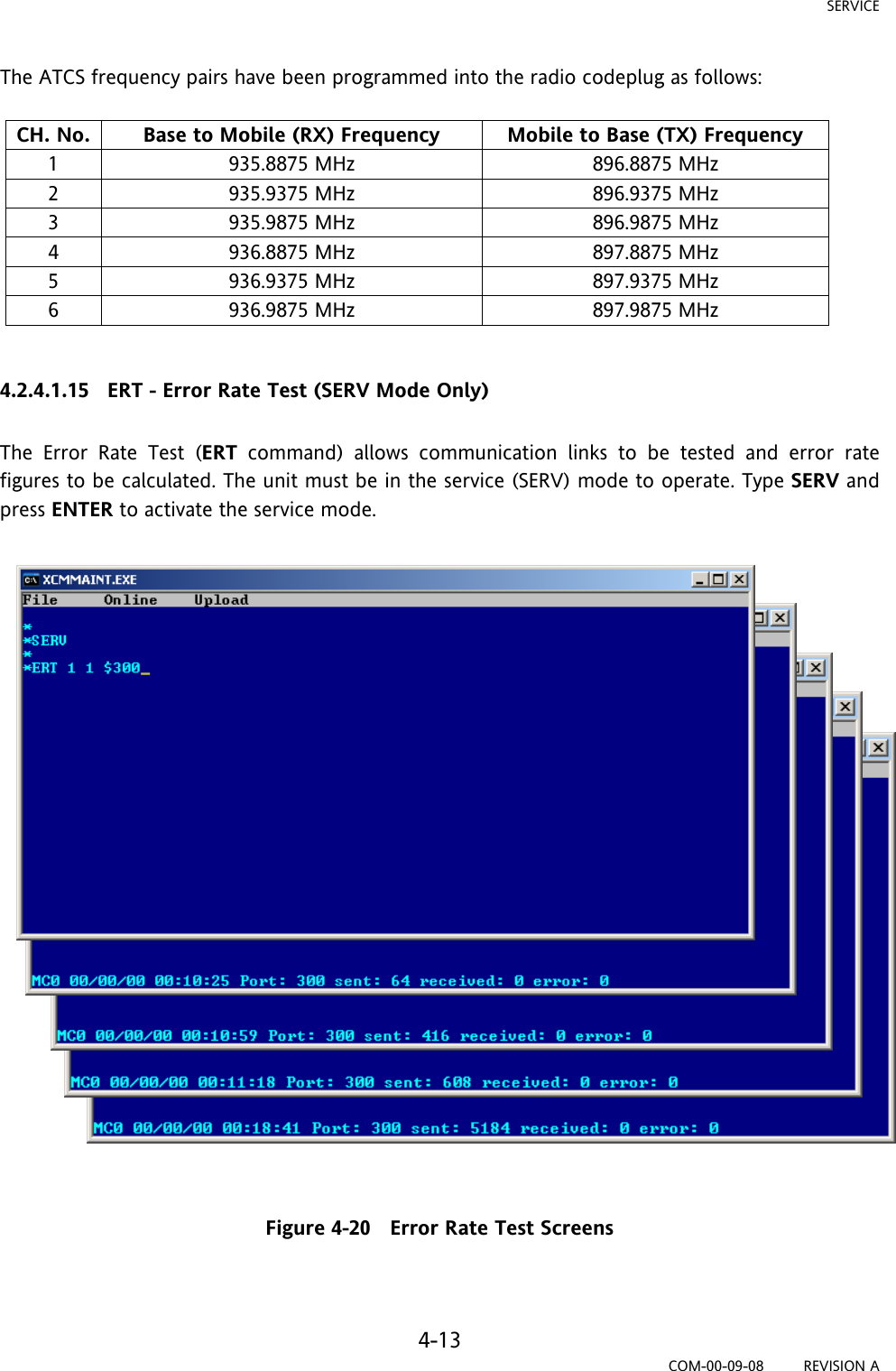
![SERVICE 4-14 COM-00-09-08 REVISION A The ERT command has the following arguments: Mode - Type of Loopback Mode 1 = open (NO) loopback 2 = digital loopback 3 = analog loopback 4 = open loop with RTS asserted (for wireline modem only) Layer - Allows user to specify layer 1 = physical layer - allows a bit error rate test to be done (For RF Channel Only) 2 = datalink layer - allows message error rate testing to be done Port - Allows user to specify port number $100 = Client Port 0 (wireline modem port on BCP) $101 = Client Port 1 (spare port on BCP) $300 = RF Channel Pattern - Byte pattern to send (hex or ASCII). If not defined, a default pattern is used. The results will be displayed at the bottom of the screen as shown in Figure 4-20. The definitions below detail the test results displayed. PORT - The port for which these results apply SENT - The number of patterns generated by this unit RECEIVED - The number of patterns correctly received by this unit ERROR - The number of patterns received that do not match the generated pattern; except for RF Channel (port $300) physical layer (layer 1) ERT commands, where this represents the number of bit errors. BER - The ratio of the total error bit count over the total received bit count (i.e., [total bit errors] / [total bits received]). This calculation applies to RF channel physical layer (layer 1) ERT commands only](https://usermanual.wiki/Invensys-Rail/9710-PS009900/User-Guide-1167782-Page-54.png)


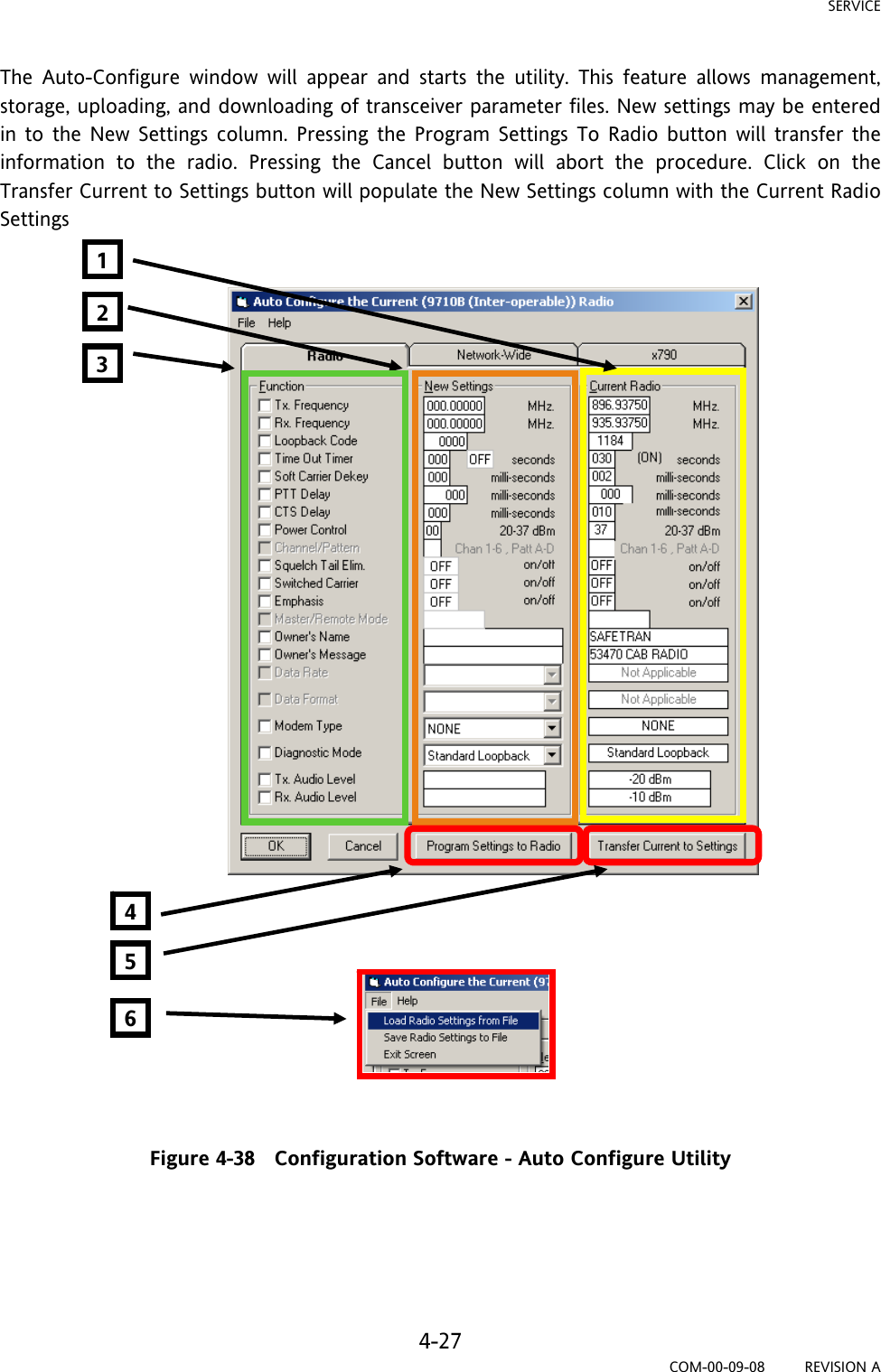
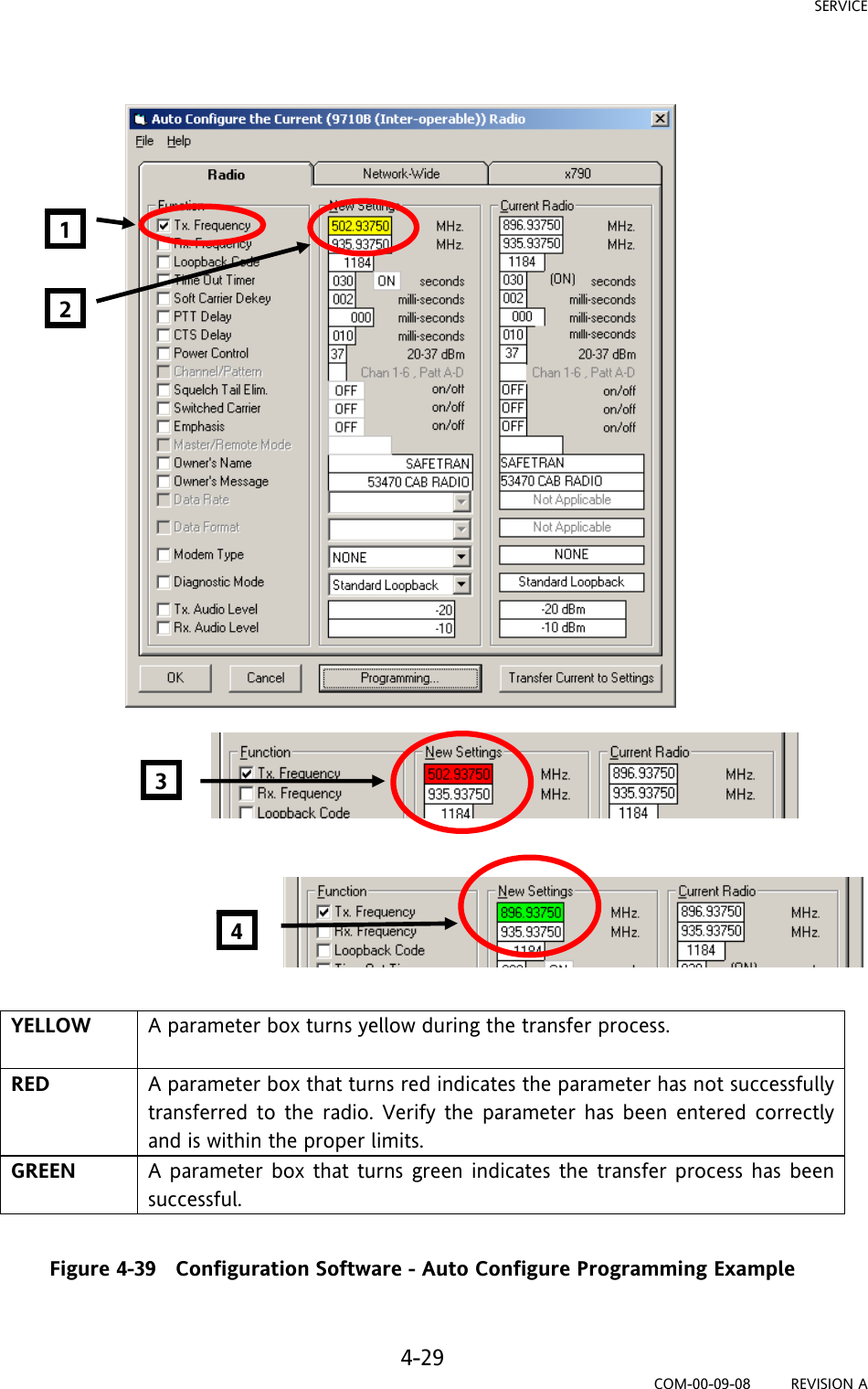
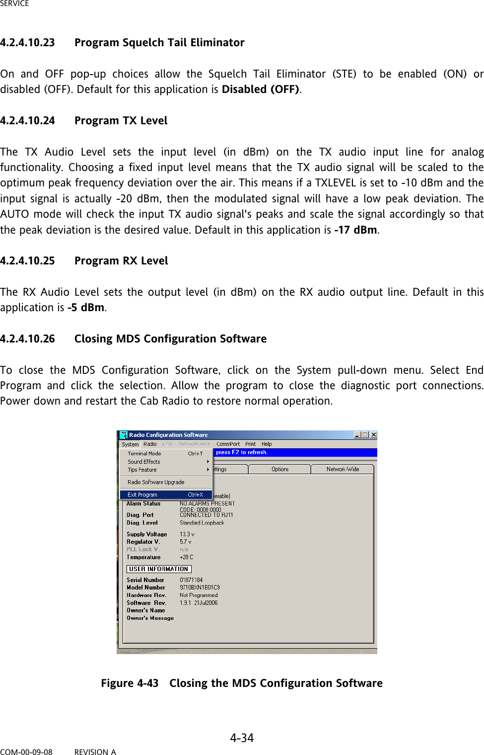
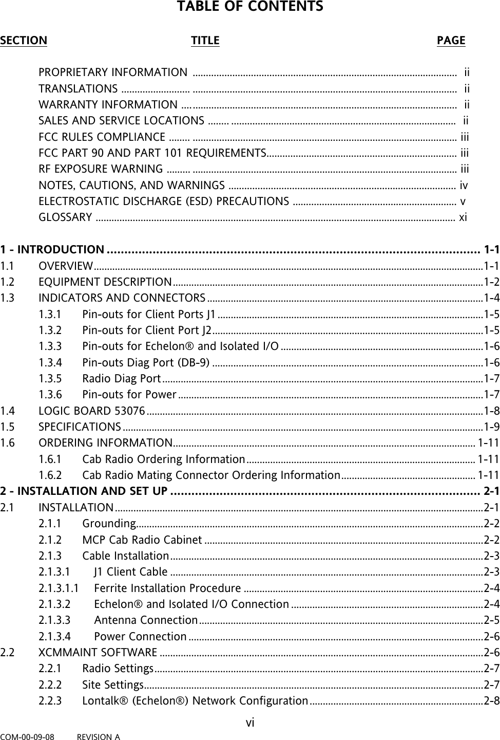
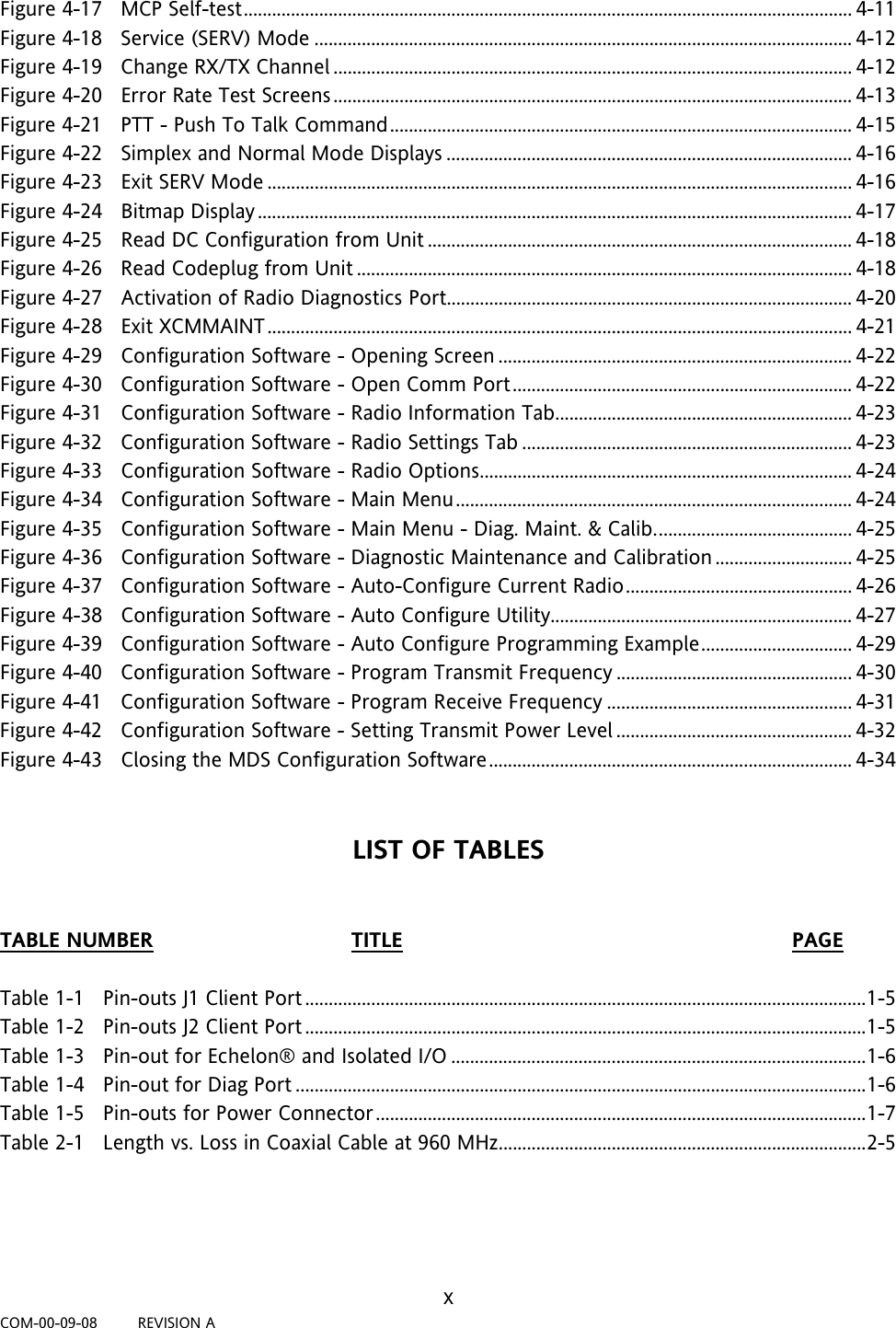
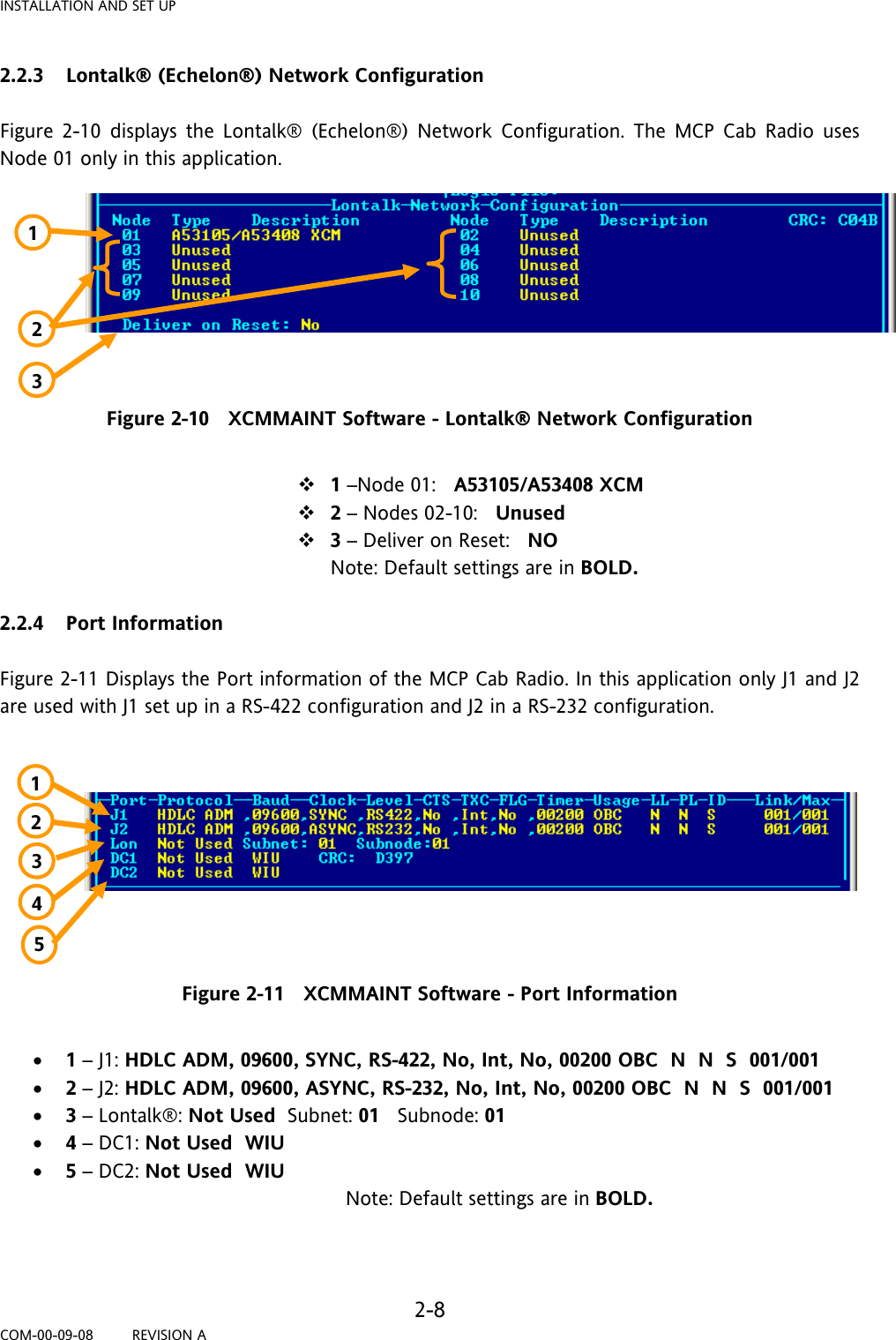
![SERVICE 4-28 COM-00-09-08 REVISION A The Auto Configure Utility components are as follows: Current Radio - This column lists the current radio configuration as read by the utility New Settings - This Column is used to enter new settings desired for the radio. Function - This column has a check box for each configurable function. To configure a function, check the box and enter the new setting in the New Settings Column. Program Settings to Radio - This button sends selected new settings to the radio. Transfer Current to Settings - This button copies and sends all of the current data in the Current Radio column to the New Settings column. File Drop Menu - The File Drop Menu has the following three functions: • Load Radio Settings from File - This selection opens a standard dialog box to open a transceiver paramenter file that has been stored on the computer. Notice the default suffix name is .RFP which is an abbreviation for Radio Parameter File. • Save Radio Settings to File - This selection opens a standard dialog box to save a transceiver parameter file that has to be stored on the computer. Notice the default filename suffix is RPF which is an abbreviation for Radio Parameter File. • Exit Screen - This function exits the Auto Configure Utility and returns control of the software to the Main Window. Auto Configure Programming Example Refer to Figure 4-39 for screen examples. To program a new transmit frequency check the box [1] to the left of Tx Frequency in the Function column. Enter the desired transmit frequency in the Tx Frequency box [2] in the New Settings Column. Press the Program Settings to Radio button. The button will indicate programming and the parameter box will turn yellow [2]. In the event the parameter did not successfully program, the parameter box in the new settings column [3] will turn red. Check the parameter and verify it is within an acceptable range for the radio. In this example the frequency was entered wrong and is out of the range of the radio and has alarmed by turning the box red. Re-enter the parameter and press the Program Settings to Radio button. The button will indicate programming and the parameter box [2] will turn yellow. If the programming was successful the parameter box [4] will turn green. Click the OK button or use the File drop menu to exit the utility. 1 2 3 4 5](https://usermanual.wiki/Invensys-Rail/9710-PS009900/User-Guide-1167782-Page-68.png)