Invensys Rail 9710-PS009900 MCP CAB RADIO User Manual Cab Radio COM 00 09 08PDF
Invensys Rail Corporation MCP CAB RADIO Cab Radio COM 00 09 08PDF
Users Manual

$50.00
PRINTED IN U.S.A.
USER'S GUIDE
MCP CAB RADIO
A53470
August 2009
DOCUMENT NO. COM-00-09-08
VERSION A
Safetran Systems Corporation, California Division
10655 7th Street, Cucamonga, California 91730
1-800-793-SAFE
Copyright © 2009 Safetran Systems Corporation, All rights reserved
ii
COM-00-09-08 REVISION A
PROPRIETARY INFORMATION
SAFETRAN SYSTEMS CORPORATION has a proprietary interest in the information contained
herein and, in some instances, has patent rights in the systems and components described. It is
requested that you distribute this information only to those responsible people within your
organization who have an official interest.
This document, or the information disclosed herein, shall not be reproduced or transferred to other
documents or used or disclosed for manufacturing or for any other purpose except as specifically
authorized in writing by SAFETRAN SYSTEMS CORPORATION.
TRANSLATIONS
The manuals and product information of SAFETRAN SYSTEMS CORPORATION are intended to be
produced and read in English. Any translation of the manuals and product information are unofficial
and can be imprecise and inaccurate in whole or in part. SAFETRAN SYSTEMS CORPORATION
does not warrant the accuracy, reliability, or timeliness of any information contained in any
translation of manual or product information from its original official released version in English and
shall not be liable for any losses caused by such reliance on the accuracy, reliability, or timeliness of
such information. Any person or entity that relies on translated information does so at his or her
own risk.
WARRANTY INFORMATION
SAFETRAN SYSTEMS CORPORATION warranty policy is as stated in the current Terms and
Conditions of Sale document. Warranty adjustments will not be allowed for products or
components which have been subjected to abuse, alteration, improper handling, or installation, or
which have not been operated in accordance with Seller's instructions. Alteration or removal of any
serial number or identification mark voids the warranty.
SALES AND SERVICE LOCATIONS
Technical assistance and sales information on SAFETRAN products may be obtained at the following
locations:
SAFETRAN SYSTEMS CORPORATION SAFETRAN SYSTEMS CORPORATION
2400 NELSON MILLER PARKWAY CALIFORNIA DIVISION
LOUISVILLE, KENTUCKY 40223 10655 7th STREET
TELEPHONE: (502) 618-8800 CUCAMONGA, CALIFORNIA 91730
FAX: (502) 618-8810 TELEPHONE: (909) 532-5300
SALES & SERVICE: (800) 626-2710 CUSTOMER SERVICE: (800) 793-7233
WEB SITE: http://www.safetran.com TECHNICAL SUPPORT: (800) 793-7233
FAX: (909) 532-5400

iii
COM-00-09-08 REVISION A
FCC RULES COMPLIANCE
The equipment covered in this manual has been tested and found to comply with the limits for a
Class B digital device, pursuant to part 15 of the FCC Rules. These limits are designed to provide
reasonable protection against harmful interference when the equipment is operated in a
commercial environment. This equipment generates, uses, and can radiate radio frequency energy
and, if not installed and used in accordance with the instruction manual, may cause harmful
interference to radio communications. Operation of this equipment in a residential area is likely to
cause harmful interference in which case the user will be required to correct the interference at
his own expense.
FCC PART 90 AND PART 101 REQUIREMENTS
This device contains a radio transceiver which operates under Parts 90.210 and 101.101 of the FCC
rules in a licensed part of the radio spectrum. It is the user's responsibility to obtain required
licensing and authorization to operate this device. Qualified personnel must perform service or
repairs to the radio portion of this device. Any unauthorized modification to the radio module,
shielding, or antenna system may void the user's authority to operate this device.
RF EXPOSURE WARNING
All antenna installation and servicing is to be performed by qualified technical personnel only.
When servicing or working at distances closer than 10 feet (3.05 meters), ensure the transmitter
has been disabled. Depending upon the application and the gain of the antenna, the total
composite power could exceed 200 watts EIRP. The antenna location should be such that only
qualified technical personnel can access it, and under normal operating conditions no other
person can come in contact or approach within 10 feet (3.05 meters) of the antenna.
This device complies with the following RF energy exposure standards and guidelines:
• United States Federal Communications Commission, 47 CFR part 2 sub-part J
• American National Standards Institute (ANSI)/Institute of Electrical and Electronic Engineers (IEEE)
C95. 1-1992
• Institute of Electrical and Electronic Engineers (IEEE) C95.1-1999 Edition
• International Commission on Non-Ionizing Radiation Protection (ICNIRP) 1998
• Ministry of Health (Canada) Safety Code 6. Limits Human Exposure to Radiofrequency
Electromagnetic Fields in the Frequency Range from 3 kHz to 300 GHz, 1999
• Australian Communications Authority Radiocommunications (Electromagnetic Radiation - Human
Exposure) Standard, 2003
• ANATEL, Brasil Regulatory Authority, Resolution 256 (April 11, 2001)

iv
COM-00-09-08 REVISION A
NOTES, CAUTIONS, AND WARNINGS
Throughout this manual, notes, cautions and warnings may be used to direct the reader’s
attention to specific information. Use of the three terms is defined as follows:
NOTE
Generally used to highlight certain information
relating to the topic under discussion.
CAUTION
APPEARS IN UPPERCASE TYPE AND REFERS TO
PROPER PROCEDURES OR PRACTICES WHICH IF NOT
STRICTLY OBSERVED, WILL RESULT IN DAMAGE TO
THE EQUIPMENT. CAUTIONS TAKE PRECEDENCE
OVER NOTES AND ALL OTHER INFORMATION,
EXCEPT WARNINGS.
WARNING
HIGHLIGHTED IN BOLD, UPPERCASE TYPE AND
APPLIES TO SAFE AND RELIABLE OPERATION OF
SAFETRAN EQUIPMENT. WARNINGS ALWAYS
TAKE PRECEDENCE OVER NOTES, CAUTIONS,
AND ALL OTHER INFORMATION.
Refer all questions to Safetran Customer Service.

v
COM-00-09-08 REVISION A
ELECTROSTATIC DISCHARGE (ESD) PRECAUTIONS
Static electricity can damage electronic circuitry, particularly low voltage components such as the
integrated circuits commonly used throughout the electronics industry. Therefore, procedures
have been adopted industry-wide which make it possible to avoid the sometimes invisible damage
caused by electrostatic discharge (ESD) during the handling, shipping, and storage of electronic
modules and components. Safetran has instituted these practices at its manufacturing facility and
encourages its customers to adopt them as well to lessen the likelihood of equipment damage in
the field due to ESD. Some of the basic protective practices include the following:
• Ground yourself before touching card cages, modules, or components.
• Remove circuit boards (modules) from card cages by the ejector lever only.
• Handle circuit boards by the edges only.
• Never physically touch the circuit board contact fingers or allow these fingers to come in
contact with an insulator (e.g., plastic, rubber, etc.).
• When not in use, place circuit boards in approved static-shielding bags, contact fingers first.
Remove circuit boards from static-shielding bags by grasping the ejector lever or the edge of
the board only. Each bag should include a caution label on the outside indicating static-
sensitive contents.
• Cover workbench surfaces used for repair of electronic equipment with static dissipative
workbench matting.
• Use integrated circuit extractor/inserter tools designed to remove and install electrostatic-
sensitive integrated circuit devices such as PROMs (OK Industries, Inc., Model EX-2 Extractor
and Model MOS-40 Inserter (or equivalent) are highly recommended).
• Utilize only anti-static cushioning material in equipment shipping and storage containers.
For information concerning ESD material applications, please contact the Safetran California
Division Technical Support Staff in Ranch Cucamonga, California. ESD Awareness Classes and
additional ESD product information are also available through the Technical Support Staff.

vi
COM-00-09-08 REVISION A
TABLE OF CONTENTS
SECTION TITLE PAGE
PROPRIETARY INFORMATION ………………………………………………………………………………………. ii
TRANSLATIONS …………………….. ………………………………………………………………………………………. ii
WARRANTY INFORMATION …. ………………………………………………………………………………………. ii
SALES AND SERVICE LOCATIONS …….. …………………………………………………………………………. ii
FCC RULES COMPLIANCE …….. ………………………………………………………………………………………. iii
FCC PART 90 AND PART 101 REQUIREMENTS……………………………………………………………… iii
RF EXPOSURE WARNING ……… ………………………………………………………………………………………. iii
NOTES, CAUTIONS, AND WARNINGS ………………………………………………………………………….. iv
ELECTROSTATIC DISCHARGE (ESD) PRECAUTIONS …………………………………………………….. v
GLOSSARY ………………………………………………………………………………………………………………………. xi
1 - INTRODUCTION .......................................................................................................... 1-1
1.1OVERVIEW .................................................................................................................................................... 1-1
1.2EQUIPMENT DESCRIPTION ...................................................................................................................... 1-2
1.3INDICATORS AND CONNECTORS ......................................................................................................... 1-4
1.3.1Pin-outs for Client Ports J1 ..................................................................................................... 1-5
1.3.2Pin-outs for Client Port J2 ....................................................................................................... 1-5
1.3.3Pin-outs for Echelon® and Isolated I/O ............................................................................. 1-6
1.3.4Pin-outs Diag Port (DB-9) ....................................................................................................... 1-6
1.3.5Radio Diag Port .......................................................................................................................... 1-7
1.3.6Pin-outs for Power .................................................................................................................... 1-7
1.4LOGIC BOARD 53076 ................................................................................................................................ 1-8
1.5SPECIFICATIONS ......................................................................................................................................... 1-9
1.6ORDERING INFORMATION ................................................................................................................... 1-11
1.6.1Cab Radio Ordering Information ....................................................................................... 1-11
1.6.2Cab Radio Mating Connector Ordering Information ................................................... 1-11
2 - INSTALLATION AND SET UP ........................................................................................ 2-1
2.1INSTALLATION ............................................................................................................................................ 2-1
2.1.1Grounding .................................................................................................................................... 2-2
2.1.2MCP Cab Radio Cabinet .......................................................................................................... 2-2
2.1.3Cable Installation ....................................................................................................................... 2-3
2.1.3.1J1 Client Cable ....................................................................................................................... 2-3
2.1.3.1.1Ferrite Installation Procedure ........................................................................................... 2-4
2.1.3.2Echelon® and Isolated I/O Connection ......................................................................... 2-4
2.1.3.3Antenna Connection ............................................................................................................ 2-5
2.1.3.4Power Connection ................................................................................................................ 2-6
2.2XCMMAINT SOFTWARE ........................................................................................................................... 2-6
2.2.1Radio Settings ............................................................................................................................. 2-7
2.2.2Site Settings ................................................................................................................................. 2-7
2.2.3Lontalk® (Echelon®) Network Configuration .................................................................. 2-8
vii
COM-00-09-08 REVISION A
2.2.4Port Information ........................................................................................................................ 2-8
3 - OPERATION ................................................................................................................. 3-1
3.1OVERVIEW .................................................................................................................................................... 3-1
3.2CAB RADIO FREQUENCY CONTROL ..................................................................................................... 3-3
3.3RADIO MESSAGES ...................................................................................................................................... 3-3
3.3.1Temporary Speed Restriction (TSR) ..................................................................................... 3-3
3.3.2Interlocking Status .................................................................................................................... 3-4
3.4POSITIVE TRAIN CONTROL ..................................................................................................................... 3-4
4 - SERVICE ...................................................................................................................... 4-1
4.1OVERVIEW .................................................................................................................................................... 4-1
4.2MCP DIAGNOSTICS.................................................................................................................................... 4-1
4.2.1Opening XCMMAINT ................................................................................................................ 4-1
4.2.2Selecting File ............................................................................................................................... 4-2
4.2.3Unit Configuration .................................................................................................................... 4-2
4.2.4Terminal Mode ........................................................................................................................... 4-3
4.2.4.1Terminal Mode Commands ............................................................................................... 4-4
4.2.4.1.1AL en/ds - Alarm Logging ...................................................................................................
4-4
4.2.4.1.2DCP - Display Codeplug ...................................................................................................... 4-5
4.2.4.1.3DDC - DC Configuration Values ....................................................................................... 4-6
4.2.4.1.4VER - Firmware Hardware Codeplug Version Information ....................................... 4-7
4.2.4.1.5BSTAT - Active Base Station Status .................................................................................. 4-7
4.2.4.1.6CSTAT - Communication Statistics .................................................................................. 4-8
4.2.4.1.7HSTAT - HDLC Statistics ...................................................................................................... 4-9
4.2.4.1.8MSTAT - Manufacturer Statistics ...................................................................................... 4-9
4.2.4.1.9LOG - Display Log .............................................................................................................. 4-10
4.2.4.1.10SL - Status Log ................................................................................................................... 4-10
4.2.4.1.11TIMERS - Display Timer Configurations ..................................................................... 4-11
4.2.4.1.12TEST restart - MCP Self-Test .......................................................................................... 4-11
4.2.4.1.13SERV - Service Command ............................................................................................... 4-12
4.2.4.1.14CHAN - Change Channel (SERV Mode Only) ........................................................... 4-12
4.2.4.1.15ERT - Error Rate Test (SERV Mode Only) ................................................................... 4-13
4.2.4.1.16PTT en/ds - Push To Talk (SERV Mode Only) ........................................................... 4-15
4.2.4.1.17SIMP en/ds - Simplex Command (SERV Mode Only) ............................................. 4-16
4.2.4.1.18Exit SERV Mode ................................................................................................................. 4-16
4.2.4.2Bit Map Display ................................................................................................................... 4-17
4.2.4.3Read DC Configuration from Unit ................................................................................ 4-18
4.2.4.4Read Codeplug from Unit ............................................................................................... 4-18
4.2.4.5Upload Codeplug to Unit ................................................................................................ 4-19
4.2.4.6Upload DC Configuration to Unit ................................................................................. 4-19
4.2.4.7Upload Logic to Unit......................................................................................................... 4-19
4.2.4.8Upload Labels to Unit ....................................................................................................... 4-20
4.2.4.9Radio Diagnostics ............................................................................................................... 4-20
4.2.4.9.1Activation of Radio Diagnostics Port ........................................................................... 4-20
4.2.4.10Radio Configuration Software ........................................................................................ 4-21
viii
COM-00-09-08 REVISION A
4.2.4.10.1Opening Radio Configuration Software ..................................................................... 4-22
4.2.4.10.2Open Com Port ................................................................................................................. 4-22
4.2.4.10.3Radio Information ............................................................................................................ 4-23
4.2.4.10.4Radio Settings .................................................................................................................... 4-23
4.2.4.10.5Options ................................................................................................................................ 4-24
4.2.4.10.6Main Menu ......................................................................................................................... 4-24
4.2.4.10.7Diagnostic Maintenance and Calibration ................................................................... 4-25
4.2.4.10.8Auto-Configure ................................................................................................................. 4-26
4.2.4.10.9Programming Transmit Frequency .............................................................................. 4-30
4.2.4.10.10Programming a Receive Frequency .......................................................................... 4-31
4.2.4.10.11Setting Transmit Power Level ..................................................................................... 4-31
4.2.4.10.12Program Time-out Timer Delay ................................................................................. 4-32
4.2.4.10.13Program Loopback Code ............................................................................................. 4-32
4.2.4.10.14Program Diagnostic Mode Level ................................................................................ 4-33
4.2.4.10.15Program CTS Delay ........................................................................................................ 4-33
4.2.4.10.16Program PTT Delay ........................................................................................................ 4-33
4.2.4.10.17Switched Carrier Mode ................................................................................................. 4-33
4.2.4.10.18Program Modem Type .................................................................................................. 4-33
4.2.4.10.19Program Emphasis .......................................................................................................... 4-33
4.2.4.10.20Program Owner's Name ............................................................................................... 4-33
4.2.4.10.21Program Owner's Message .......................................................................................... 4-33
4.2.4.10.22Program Soft Carrier Dekey Delay ............................................................................ 4-33
4.2.4.10.23Program Squelch Tail Eliminator ............................................................................... 4-34
4.2.4.10.24Program TX Level ........................................................................................................... 4-34
4.2.4.10.25Program RX Level ........................................................................................................... 4-34
4.2.4.10.26Closing MDS Configuration Software ....................................................................... 4-34

ix
COM-00-09-08 REVISION A
LIST OF FIGURES
FIGURE NUMBER TITLE PAGE
Figure 1-1 A53470 MCP Cab Radio ................................................................................................................... 1-1
Figure 1-2 Cab Radio Block Diagram ............................................................................................................... 1-2
Figure 1-3 Cab Radio Views ................................................................................................................................ 1-3
Figure 1-4 Indicators and Connectors ............................................................................................................. 1-4
Figure 1-5 Radio Diag Port Pin-out ................................................................................................................... 1-7
Figure 1-6 Logic Board Access Panel ................................................................................................................ 1-8
Figure 2-1 Pem Nut Locations ............................................................................................................................ 2-1
Figure 2-2 Mounting Dimensions ...................................................................................................................... 2-1
Figure 2-3 Chassis Grounding Screws .............................................................................................................. 2-2
Figure 2-4 Cable Installation ............................................................................................................................... 2-3
Figure 2-5 Installing Ferrite Filter on Data Cable ......................................................................................... 2-4
Figure 2-6 Completed Ferrite Installation ...................................................................................................... 2-4
Figure 2-7 XCMMAINT Software - Version Verification ............................................................................. 2-6
Figure 2-8 XCMMAINT Software - Radio Settings ........................................................................................ 2-7
Figure 2-9 XCMMAINT Software - Site Settings ............................................................................................ 2-7
Figure 2-10 XCMMAINT Software - Lontalk® Network Configuration .................................................. 2-8
Figure 2-11 XCMMAINT Software - Port Information ................................................................................. 2-8
Figure 3-1 Locomotive Configuration .............................................................................................................. 3-1
Figure 3-2 Typical Network Configuration ..................................................................................................... 3-2
Figure 3-3 Cab Radio Frequency Control ....................................................................................................... 3-3
Figure 3-4 Temporary Speed Restriction Example ....................................................................................... 3-3
Figure 3-5 Interlocking Status ............................................................................................................................ 3-4
Figure 3-6 PTC Display .......................................................................................................................................... 3-4
Figure 4-1 Opening XCMMAINT ........................................................................................................................ 4-1
Figure 4-2 Filename Select .................................................................................................................................. 4-2
Figure 4-3 Opening Screen ................................................................................................................................. 4-2
Figure 4-4 Terminal Mode ................................................................................................................................... 4-3
Figure 4-5 Terminal Mode - Help Screen ....................................................................................................... 4-3
Figure 4-6 Display Alarms .................................................................................................................................... 4-4
Figure 4-7 Display Codeplug Contents ............................................................................................................ 4-5
Figure 4-8 Display DC Configuration ................................................................................................................ 4-6
Figure 4-9 Version Identification ....................................................................................................................... 4-7
Figure 4-10 Base Station List .............................................................................................................................. 4-7
Figure 4-11 Communication Statistics ............................................................................................................. 4-8
Figure 4-12 HDLC Statistics ................................................................................................................................. 4-9
Figure 4-13 Manufacturer Statistics .................................................................................................................. 4-9
Figure 4-14 View Log ......................................................................................................................................... 4-10
Figure 4-15 Status Log ....................................................................................................................................... 4-10
Figure 4-16 Timer Status ................................................................................................................................... 4-11

x
COM-00-09-08 REVISION A
Figure 4-17 MCP Self-test ................................................................................................................................. 4-11
Figure 4-18 Service (SERV) Mode .................................................................................................................. 4-12
Figure 4-19 Change RX/TX Channel .............................................................................................................. 4-12
Figure 4-20 Error Rate Test Screens .............................................................................................................. 4-13
Figure 4-21 PTT - Push To Talk Command .................................................................................................. 4-15
Figure 4-22 Simplex and Normal Mode Displays ...................................................................................... 4-16
Figure 4-23 Exit SERV Mode ............................................................................................................................ 4-16
Figure 4-24 Bitmap Display .............................................................................................................................. 4-17
Figure 4-25 Read DC Configuration from Unit .......................................................................................... 4-18
Figure 4-26 Read Codeplug from Unit ......................................................................................................... 4-18
Figure 4-27 Activation of Radio Diagnostics Port ...................................................................................... 4-20
Figure 4-28 Exit XCMMAINT ............................................................................................................................ 4-21
Figure 4-29 Configuration Software - Opening Screen ........................................................................... 4-22
Figure 4-30 Configuration Software - Open Comm Port ........................................................................ 4-22
Figure 4-31 Configuration Software - Radio Information Tab ............................................................... 4-23
Figure 4-32 Configuration Software - Radio Settings Tab ...................................................................... 4-23
Figure 4-33 Configuration Software - Radio Options ............................................................................... 4-24
Figure 4-34 Configuration Software - Main Menu .................................................................................... 4-24
Figure 4-35 Configuration Software - Main Menu - Diag. Maint. & Calib. ......................................... 4-25
Figure 4-36 Configuration Software - Diagnostic Maintenance and Calibration ............................. 4-25
Figure 4-37 Configuration Software - Auto-Configure Current Radio ................................................ 4-26
Figure 4-38 Configuration Software - Auto Configure Utility ................................................................ 4-27
Figure 4-39 Configuration Software - Auto Configure Programming Example ................................ 4-29
Figure 4-40 Configuration Software - Program Transmit Frequency .................................................. 4-30
Figure 4-41 Configuration Software - Program Receive Frequency .................................................... 4-31
Figure 4-42 Configuration Software - Setting Transmit Power Level .................................................. 4-32
Figure 4-43 Closing the MDS Configuration Software ............................................................................. 4-34
LIST OF TABLES
TABLE NUMBER TITLE PAGE
Table 1-1 Pin-outs J1 Client Port ....................................................................................................................... 1-5
Table 1-2 Pin-outs J2 Client Port ....................................................................................................................... 1-5
Table 1-3 Pin-out for Echelon® and Isolated I/O ........................................................................................ 1-6
Table 1-4 Pin-out for Diag Port ......................................................................................................................... 1-6
Table 1-5 Pin-outs for Power Connector ........................................................................................................ 1-7
Table 2-1 Length vs. Loss in Coaxial Cable at 960 MHz .............................................................................. 2-5

xi
COM-00-09-08 REVISION A
GLOSSARY
AAR: Association of American Railroads - An organization that establishes uniformity
and standardization among different railroad systems.
ABM: Asynchronous Balance Mode – Used as an identifier for a HDLC protocol.
ADM: Asynchronous Disconnect Mode – Used as an identifier for a HDLC protocol.
AEI: Automatic Equipment Identification - Equipment installed at sites along the
track to read and report train consist information.
ARES: Advanced Railroad Electronics System - Made by Rockwell International as an
alternative to AAR ATCS.
ATCS: Advanced Train Control System - A set of standards compiled by the AAR for
controlling all aspects of train operation.
BCP: Base Communications Package - Defined by the ATCS specifications as the
transmitter / receiver base station and associated processors to handle
communications between mobile and central office equipment.
BER: Bit Error Rate - Expresses the quality of a communications in the number of
errors per bits sent.
BPSK: Binary Phase Shift Keying - A method of modulating a carrier signal to carry two
bits of information in every cycle.
CBT: Common Base Technology – A term referring to product design using a
modular based approach.
CC: Cluster Controller - An ATCS ground network node responsible for the control
of BCP’s.
CPC: Central Protocol Converter - Modular component of Safetran’s R/Link™ Radio
Control System that converts CTC code line control and indication message data
to ATCS-compatible data.
CRC: Cyclic Redundancy Check - The CRC on a data packet is normally calculated and
appended to the data so that the receiver can verify that no data was lost or
corrupted during transit.

xii
COM-00-09-08 REVISION A
GLOSSARY
CMSA/CA: Carrier-Sense-Multiple-Access/Collision Avoidance - A scheme for allowing
multiple transmitters sharing a single medium to cooperatively timeshare with a
minimum of overlap and interference.
CTC: Central Traffic Control System
CTS: Clear To Send
dB: Abbreviation for decibel. The standard unit for expressing transmission gain or
loss and relative power levels. Decibels indicate the log ratio of power output to
power input.
dBi: Abbreviation for decibels referenced to an isotropic (unipole) antenna.
dBm: Abbreviation for decibels above (or below) one milliwatt.
DCE: Data Communications Equipment - A device that merely transports but does
not originate or consume data.
DEVICE: Specific to the Contents Listing, MCF Approval Listing, and Diagnostic Terminal
Utility, a device represents the smallest possible breakdown of an ATCS address
which may identify a Virtual Circuit, cut section, signal SAT, module, etc.
DTE: Data Terminal Equipment - Any device (printer, terminal, PC, host computer)
that originates or consumes data over a transmission facility.
EIA: Electronics Industries Association - A standards organization in the U.S.
specializing in the electrical and functional characteristics of interface
equipment.
ECP:
Emergency Control Protocol
ERP: Effective Radiated Power - The product of the antenna power (transmitter
power less transmission-line loss) times either the antenna power gain or the
antenna field gain squared.
FEP: Front End Processor - An ATCS ground network node responsible for providing
network access to ground host and terminal users (provides network
interfacing).

xiii
COM-00-09-08 REVISION A
GLOSSARY
FIFO: First In, First Out - A buffer or shift register configured so that the first data
queued is the first data de-queued - i.e. the sequence is preserved.
FSK: Frequency Shift Keying - A baseband modulation technique that conveys digital
information over analog facilities by associative discrete logical states with pre-
defined frequencies.
GENI (F): Genesys Field Protocol
GENI (O):
Genesys Office Protocol
HAYES AT
COMMAND:
A set of commands defined by the Hayes Corporation for the control and
configuration of modems.
HDLC: High-level Data Link Control - A serial protocol for exchanging synchronous
information.
IP: Internet Protocol - ISO Model Layer 3 (network) protocol that performs proper
routing of packets.
LAN: Local Area Network - A limited network where the data transfer medium is
generally wires or cable.
LINK MARGIN: The amount of received signal strength beyond the receiver threshold reserved
to compensate for normal signal fluctuations.
LSB: Least Significant Bit of a binary number (having the lowest numerical weight)
MCP/WCP: Mobile/Wayside Communications Package - The radio and associated processor
used by mobile and wayside ATCS compatible equipment to communicate to
the central office.
MCP: Mobile Communications Package - The radio and associated processor used by
mobile ATCS compatible equipment to communicate to the central office.
MCS: Harmon Protocol
MSB: Most Significant Bit of a binary number (having the greatest numerical weight)
NUL: Null – Used as an identifier for a HDLC protocol.

xiv
COM-00-09-08 REVISION A
GLOSSARY
NULL MODEM: A cable or other device that connects two DTE devices directly by emulating the
physical connections of a DCE (the Transmit output of each DTE is connected to
the Receive input of the other DTE).
POL Polled – Used as an identifier for a HDLC protocol.
RCI: Receive Clock In
RS232: EIA interface standard between DTE and DCE, employing serial binary data
interchange.
RS422: EIA interface standard that extends transmission speeds and distances beyond
RS232, employing a balanced-voltage system with a high level of noise
immunity.
RSSI: Received Signal Strength Indication - A numerical value indicating the relative
strength of received carrier.
RTS: Ready To Send
RTU: Remote Terminal Unit - Also known as Field Code Unit or Code Unit. Used to
perform non-vital I/O under control of a central office unit.
RXD: Receive Data
SCS: Safetran Code System
SSI: Signal Strength Indicator - A measure of the relative strength of an incoming RF
signal when it was received by a BCP.
SSR: Spread Spectrum Radio - A transmitter/receiver that uses a method of radio
transmission in which the transmitted energy is evenly spread over the
complete bandwidth of the radio, resulting in small RF signature.
TCI: Transmit Clock In
TCO: Transmit Clock Out

xv
COM-00-09-08 REVISION A
GLOSSARY
TCP/IP: Transmission Control Protocol/Internet Protocol - The Internet protocol used to
connect a world-wide internetwork of universities, research laboratories,
military installations, organizations, and corporations. The TCP/IP includes
standards for how computers communicate and conventions for connecting
network and routing traffic.
TXD: Transmit Data
UDP: User Datagram Protocol - A transport protocol used primarily for the
transmission of network management information. Not as reliable as TCP.
WIU: Wayside Interface Unit
xvi
COM-00-09-08 REVISION A
This Page Intentionally Left Blank

INTRODUCTION
1-1
COM-00-09-08 REVISION A
SECTION 1
INTRODUCTION
1 - INTRODUCTION
1.1 OVERVIEW
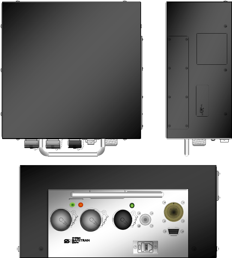
The Mobile Communications Package (MCP) Cab Radio 53470 is a ruggedized unit for on board
applications (e.g., locomotive) of the Safetran 53411 Wayside Communications Package (WCP).
Mil-spec type connectors are used for power and I/O client ports. A two piece metal housing
encapsulates the components.
Figure 1-1 A53470 MCP Cab Radio

INTRODUCTION
1-2
COM-00-09-08 REVISION A
1.2 EQUIPMENT DESCRIPTION
The 53470 Cab Radio consists of a UHF radio and 30 watt RF power amplifier. The Safetran 53076
Logic Board serves as an interface between the radio and the I/O data as well as a control head
for radio operation. Mil-spec Client I/O ports A Type-N RF connector is provided for an external
antenna. Diagnostic ports are panel mounted for the radio (RJ-11) and the logic card (DB-9).
Figure 1-2 Cab Radio Block Diagram
30 Watt Power
Amplifier
N Type
Antenna Port
A53076 Control Head Logic Board
Client
User Port DB-9 Diag Port
UHF Radio RF/Radio Analog Data
RF/Radio Analog Data
Radio Analog Data/Digital Control
User Port Data
Digital Control
Simulated User Port Data
Radio
Diagnostics Port
Client
User Port
Echelon®/Isolated I/O
Echelon® and
Isolated I/O
INTRODUCTION
1-3
COM-00-09-08 REVISION A
Three LEDs have been extended from the logic card to the cabinet front panel for RF Transmit, RX
Receive, and Power/Health Check indications. Other indicators and switches used on the WCP
CPU-II are accessible via a panel on the side of the unit.
Figure 1-3 Cab Radio Views
TO BE REMOVED BY AUTHORIZED
PERSONNEL ONLY
00000000
RF
RX TX
CLIENT
PORT 1
(J1) CLIENT
PORT 2 (J2) ECH I/O
& OPTO I/O
POWER
RF
POWER
DIAG
A53470 CAB RADIO DIAG
RADIO
FRONT
TOP
SIDE
INTRODUCTION
1-4
COM-00-09-08 REVISION A
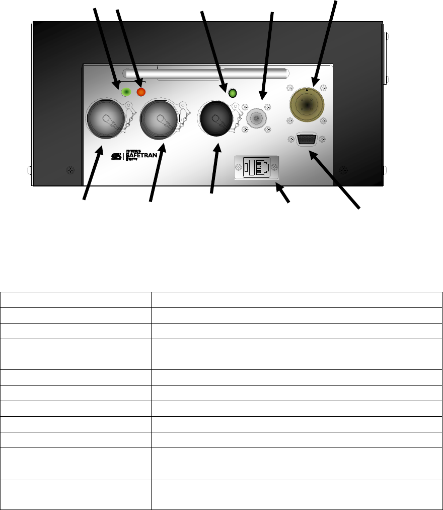
1.3 INDICATORS AND CONNECTORS
Figure 1-4 details the indicators and connectors on the 53470 Cab Radio.
Figure 1-4 Indicators and Connectors
INDICATOR/CONNECTOR DESCRIPTION
RX LED (Green) Illuminates when signal is being received.
TX LED (Red) Illuminates when transmitter is active.
Power/Health LED (Green) Illuminates when power is on and flashes at 1 Hz
indicating good health.
Antenna Type-N RF connector for external antenna.
Power Mil-Spec 4-pin male connector for 12 VDC input power.
Client Port 1 Mil-Spec 15-pin male connector for Data I/O
Client Port 2 Mil-Spec 15-pin male connector for Data I/O
Echelon®/Opto I/O Mil-Spec 10-pin male connector for Echelon® I/O
Radio Diagnostics RJ-11 connector for connection of computer to radio
internal diagnostics using applicable software.
Logic Board Diagnostics DB-9 female connector for connection to the Logic Board
diagnostic program for set up Logic Control functions.
00000000
RF
RX TX
CLIENT
PORT 1
(J1) CLIENT
PORT 2 (J2) ECH I/O
& OPTO I/O
POWER
RF
POWER
DIAG
A53470 CAB RADIO DIAG
RADIO
RX
LED
TX
LED
Power/Health
LED
Type-N
Antenna
Out
Client Port 1 Client Port 2 Echelon® I/O
Opto I/O
Radio
Diag Port
WCP
Diagnostics
Power

INTRODUCTION
1-5
COM-00-09-08 REVISION A
1.3.1 Pin-outs for Client Ports J1
The following is the pin-out description for the J1 Client Port.
Table 1-1 Pin-outs J1 Client Port
Pin Signal Name I/O Description
B TXCO1- O Tx Clock -
C TXCO+ O Tx Clock +
D TXD1- O Tx Data -
E TXD1+ O Tx Data +
F RXC1- I Rx Clock -
G RXC1+ I Rx Clock +
H RXD1- I Rx Data -
J RXD1+ I Rx Data +
P Shield - -
R Ground - -
A, K, L, M, N Not Used - -
1.3.2 Pin-outs for Client Port J2
The following is the pin-out description for the J2 Client Port.
Table 1-2 Pin-outs J2 Client Port
Pin Signal Name I/O Description
B TXCO2- O Tx Clock -
C TXCO2+ O Tx Clock +
D TXD2- O Tx Data -
E TXD2+ O Tx Data +
F RXC2- I Rx Clock -
G RXC2+ I Rx Clock +
H RXD2- I Rx Data -
J RXD2+ I Rx Data +
P Shield - -
R Ground - -
A, K, L, M, N Not Used - -

INTRODUCTION
1-6
COM-00-09-08 REVISION A
1.3.3 Pin-outs for Echelon® and Isolated I/O
The following is the pin-out description for the Echelon® and Isolated I/O port.
Table 1-3 Pin-out for Echelon® and Isolated I/O
Pin Signal Name I/O Description
A IA I General Purpose Input
B IB I General Purpose Input
C OC O General Purpose Output
D OD O General Purpose Output
E ECH 1A I/O Echelon Twisted Pair
Not Polarity Sensitive
F ECH 1B I/O Echelon Twisted Pair
Not Polarity Sensitive
G, H, J, K Not Used - -
1.3.4 Pin-outs Diag Port (DB-9)
The following is the pin-out description for the DB-9 Diag Port.
Table 1-4 Pin-out for Diag Port
Pin Signal Name I/O Description
1 Chassis Ground - Chassis Ground
2 TXD O RS-232 Transmit Data
RS-232 Voltage Levels
3 RXD I RS-232 Receive Data
RS-232 Voltage Levels
5 Digital Ground - Digital Ground
7 CTS I Clear To Send
RS-232 Voltage Levels
8 RTS O Request To Send
RS-232 Levels
4, 6, and 9 Not Used - -
INTRODUCTION
1-7
COM-00-09-08 REVISION A
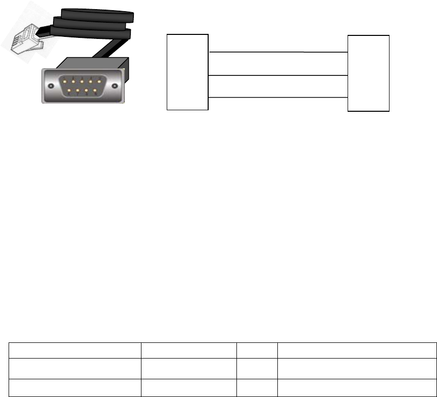
1.3.5 Radio Diag Port
The following is the pin-out description for the Radio Diag Port.
Figure 1-5 Radio Diag Port Pin-out
1.3.6 Pin-outs for Power
The following is the pin-out description for the Power connector.
Table 1-5 Pin-outs for Power Connector
Pin Signal Name I/O Description
B Batt/Pwr- - Battery/Power-
D Batt/Pwr+ - Battery/Power+
TXD
RXD
GND
TXD
RXD
GND
4
5
6
3
5
2
RJ-11 PLUG
(TO RADIO)
DB-9 FEMALE
(TO COMPUTER)
INTRODUCTION
1-8
COM-00-09-08 REVISION A
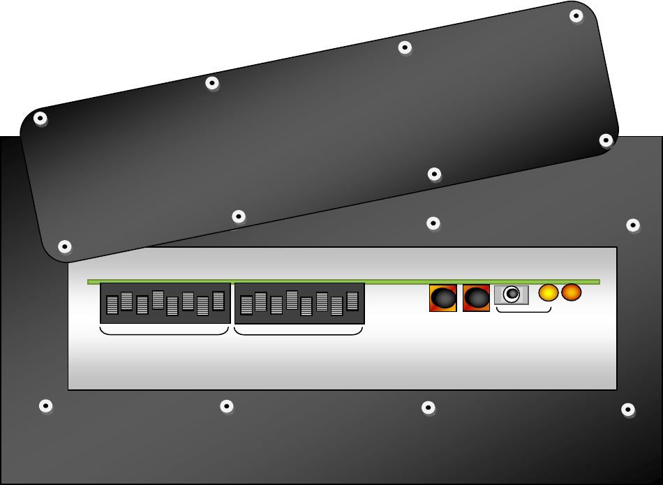
1.4 LOGIC BOARD 53076
The Cab Radio 53076 Logic Board is the control interface that directs data flow and controls the
radio operations. An access panel on the side of the cab radio enclosure for setup and servicing.
Normal operation does not require access to the Logic Board. The access panel has a gasket seal
out dirt and moisture. Figure 1-6 displays the Logic Board indicators and controls used for setup
and troubleshooting.
Figure 1-6 Logic Board Access Panel
R
X
D
T
X
D
TCO
RCI
RTS
CTS
TCI
TCI
CTS
RTS
RCI
TCO
T
X
D
R
X
D
1 3 4 5 6 7
8 10
9
11
12
13
14
15
16
2
SELECT
ENTER
SERVICE
LAN
INTRODUCTION
1-9
COM-00-09-08 REVISION A
1.5 SPECIFICATIONS
PRIMARY POWER
Input Voltage: 13.8 VDC Nominal (11.5 to 16.0 VDC)
Input Isolation: Non-isolated
Power Consumption:
Rx: 400 mA @ 12V
Tx @ 30 W: 10.8A @ 12V
Reverse Polarity Protection Diode across primary input
PHYSICAL
Dimensions: 11.25 inches (28.58 centimeters) wide
4.25 inches (10.80 centimeters) high
9.75 inches (24.77 centimeters) deep
10.75 inches (27.31centimeters) deep (with handle)
Package Weight: 12 pounds (5.44 kilograms)
ENVIRONMENTAL
Operating Temperature Range: -22 °F to +140 °F (-30 °C to +60 °C)
Humidity: 95% @ 40° C non-condensing
TRANSMITTER
Frequency Range: 800-960 MHz
Modulation Type: Binary CPFSK
Audio Input Level: -20 dBm to +5 dBm
Carrier Power
Transmitter Exciter:
Power Amplifier:
Maximum 5 Watts (+37 dBm)
Maximum 30 Watts (+45 dBm)
Duty Cycle: Continuous
Output Impedance: 50 ohms
Frequency Stability: 1.5 ppm, - 30 ° C to +60° C
Channel Spacing: 12.5 kHz
Spurious & Harmonic: -65 dBc per EIA test specification
Intermodulation -40 dBc
Time-out Timer: 1-255 seconds (30 seconds default)
Transmitter: Data Activated or RTS
Response Time: 5 ms
Maximum FM modulation ±2.5 kHz
FCC Emission Designators E5MDS9710N-1 (806-940 MHz)
INTRODUCTION
1-10
COM-00-09-08 REVISION A
RECEIVER
Type: Double conversion super-heterodyne
Frequency Range: 800-960 MHz
Frequency Stability: ±1.5 ppm, -30° C to +60° C
Sensitivity: 12 dB SINAD @ -110 dBm
Spurious & Image Rejection: 70 dB Minimum
Inter-modulation Response
Rejection:
65 dB Minimum per EIA specification
Selectivity: 65 dB Minimum, 12.5 kHz channel
Bandwidth: 12.5 kHz
Desensitization: 65 dB Minimum, 12.5 kHz channel
Bit-Error Rates: 1200 bps: 1 x 10⁻⁶ @ -110 dBm
4800 bps: 1 x 10⁻⁶ @ -110 dBm
9600 bps: 1 x 10⁻⁶ @ -108 dBm
POWER AMPLIFIER
Frequency
Forward:
Reverse:
896.5-898 MHz
935.5-937 MHz
Carrier Power (5 watts drive): 30 watts
Forward Gain: 8 dB
Forward Gain Variation
Over Operating Temperature:
±0.25 dB
Input VSWR (50 ohms): 1.5:1 Typical, 2:1 Maximum
PTT Delay: 10 µS Maximum
PTT Logic (Forward Path Select): 0.8 V Maximum
PTT Logic (Reverse Path Select): 2.8 V Minimum to 5.5 V Maximum
RF Rise/Fall Time: 1 µS
RF Input Level: 20 watts Maximum
Duty Factor: 20%
Transmit Duration: 5 Minutes
Harmonics: 60 dBc
Spurious: 60 dBc
Maximum VSWR Infinite
Reverse Insertion Loss: 2.0 dB Maximum
Reverse Amplitude Variation: ±0.25 dB Maximum
Reverse Amplitude Variation
Over Operating Temperature:
±0.25 dB Maximum

INTRODUCTION
1-11
COM-00-09-08 REVISION A
1.6 ORDERING INFORMATION
The following is ordering information for the MCP Cab Radio and optional cabling.
1.6.1 Cab Radio Ordering Information
Description
Safetran Order Number
MCP Cab Radio 9000-53470-0001
1.6.2 Cab Radio Mating Connector Ordering Information
Description
Quantity
Included
Safetran Order Number
10-pin I/O Port mating connector 0 Z701-00061-3116
(Mfg. Part No. MS3116F12-10S-SR)
15-pin Client Port mating connector 0 Z714-9024-3116
(Mfg. Part No. MS3116F14-15SR)
4-pin Power mating connector and
power Cable 3 ft
0 9000-26697-0001
4-pin Power mating connector and
power Cable 5 ft
0 9000-26697-0002
4-pin Power mating connector and
power cable 10 ft
0 9000-26697-0003
INTRODUCTION
1-12
COM-00-09-08 REVISION A
This Page Intentionally Left Blank
INSTALLATION AND SETUP
2-1
COM-00-09-08 REVISION A
SECTION 2
INSTALLATION AND SETUP
2 - INSTALLATION AND SET UP
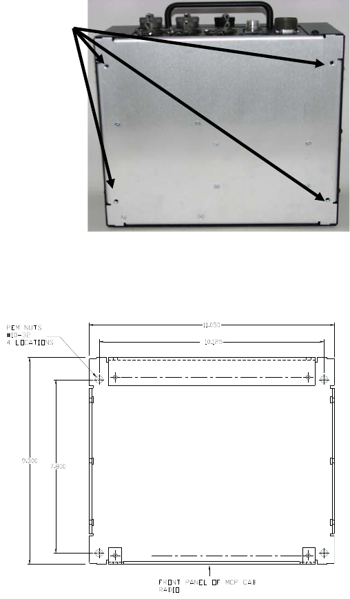
2.1 INSTALLATION
The MCP Cab Radio is equipped with four (4) #10-32 pem nuts to secure the unit to a wall or
shelf as shown in Figure 2-1.
Figure 2-1 Pem Nut Locations
Figure 2-2 displays the pem nut dimensions in addition to the dimensions of the MCP Cab Radio
cabinet. Provide ample space for installation of the power, antenna, and client port connectors
Figure 2-2 Mounting Dimensions
BB
BB
PEM NUTS #10-32
4 Locations
INSTALLATION AND SET UP
2-2
COM-00-09-08 REVISION A
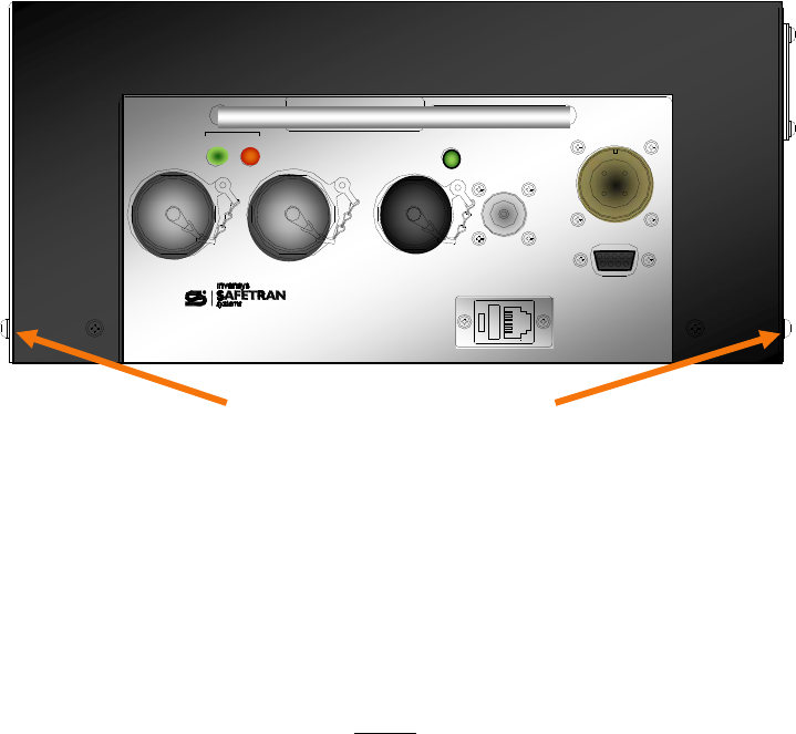
2.1.1 Grounding
A grounding screw is located on each side of the unit as shown in Figure 2-3. The radio must be
grounded to the locomotive chassis to avoid undesired ground loops with peripheral equipment
connected to the MCP Cab Radio and maintain lightening and power transients.
Figure 2-3 Chassis Grounding Screws
2.1.2 MCP Cab Radio Cabinet
NOTE
Tighten all cabinet screws by hand. Do not use
power screw drivers or over-tighten screws. Ensure
all screws are in place and secure to maintain
physical and electrical seal.
The MCP Cab Radio is secured with two screws on the front and rear and three screws on each
side with the front screw on each side equipped for grounding the cabinet. It is important to not
to over tighten these screws. Use of power screw drivers is not advised.
00000000
RF
RX TX
CLIENT
PORT 1
(J1) CLIENT
PORT 2 (J2) ECH I/O
& OPTO I/O
POWER
RF
POWER
DIAG
A53470 CAB RADIO DIAG
RADIO
Chassis Grounding Screws
INSTALLATION AND SETUP
2-3
COM-00-09-08 REVISION A
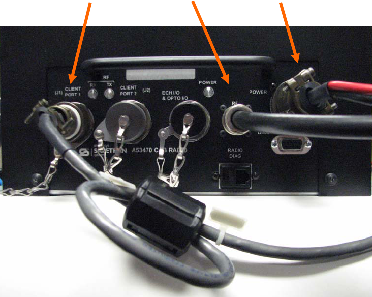
2.1.3 Cable Installation
The MCP Cab Radio uses Mil-spec type twist connectors for Client ports, Echelon®/Opto-I/O, and
Power. The MCP Cab Radio is equipped with an N-Type RF connector for connecting the external
antenna to the radio. In most applications, Client Port J1, Antenna, and Power will be used as
shown in Figure 2-4.
Figure 2-4 Cable Installation
2.1.3.1 J1 Client Cable
The J1 Client Cable interfaces the MCP Cab Radio to the locomotive on-board computer (or other
peripheral equipment if used in another application). The default protocol for this port is RS-422
or as configured in the unit's codeplug. A ferrite filter is required on the J1 Client Cable to
eliminate EMI/RFI interference. Use the following procedure to install the filter on to the data
cable.
J1 Client Port Antenna Power
INSTALLATION AND SET UP
2-4
COM-00-09-08 REVISION A
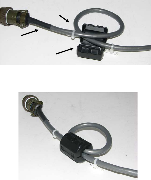
2.1.3.1.1 Ferrite Installation Procedure
1. Using the ferrite filter provided with the MCP Cab Radio (Fairrite Model 0431164181), open the
ferrite case and loop the data cable through the filter so the cable goes through the filter core
twice as shown in Figure 2-5. Mount the ferrite filter as close to the connector as possible. Figure
2-6 shows the completed ferrite filter installation.
Figure 2-5 Installing Ferrite Filter on Data Cable
Figure 2-6 Completed Ferrite Installation
2.1.3.2 Echelon® and Isolated I/O Connection
A 10-pin mil-spec connector provides an Echelon® I/O connection and two (2) isolated inputs and
outputs.
Ferrite Filte
r
(Fairrite Model 0431164181)
15-pin Client Port Cable
Loop wire through filter
twice as shown.
Completed Cable

INSTALLATION AND SETUP
2-5
COM-00-09-08 REVISION A
2.1.3.3 Antenna Connection
WARNING
ALL ANTENNA INSTALLATION AND SERVICING IS
TO BE PERFORMED BY QUALIFIED TECHNICAL
PERSONNEL ONLY. WHEN SERVICING OR
WORKING AT DISTANCES CLOSER THAN 3.05
METERS, ENSURE THE TRANSMITTER HAS BEEN
DISABLED. DEPENDING UPON THE APPLICATION
AND THE GAIN OF THE ANTENNA, THE TOTAL
COMPOSITE POWER COULD EXCEED 200 WATTS
EIRP. THE ANTENNA LOCATION SHOULD BE
SUCH THAT ONLY QUALIFIED TECHNICAL
PERSONNEL CAN ACCESS IT, AND UNDER
NORMAL OPERATING CONDITIONS NO OTHER
PERSON CAN COME IN CONTACT OR APPROACH
WITHIN 10 FEET (3.05 METERS) OF THE
ANTENNA.
The MCP Cab Radio is equipped with an N-Type antenna connector. Selection of an antenna feed
line is important. A high quality low-loss cable should be used. Poor quality cable will result in
power losses that may reduce the range and reliability of the radio system. Table 2-1 shows the
losses that will occur when using various types and lengths of cable at 960 MHz Cable length
should be kept as short as possible to minimize signal loss.
Table 2-1 Length vs. Loss in Coaxial Cable at 960 MHz
Cable Type
10 Feet
(3.05 Meters)
50 Feet
(15.24 Meters)
100 Feet
(30.48 Meters)
500 Feet
(152.4 Meters)
RG08A/U 0.51 dB 2.53 dB 5.07 dB 25.35 dB
1/2 inch HELIAX 0.12 dB 0.76 dB 1.15 dB 7.55 dB
7/8 inch HELIAX 0.08 dB 0.42 dB 0.83 dB 4.15 dB
1-1/4 inch HELIAX 0.06 dB 0.31 dB 0.62 dB 3.10 dB
1-5/8 inch HELIAX 0.05 dB 0.26 dB 0.52 dB 2.60 dB

INSTALLATION AND SET UP
2-6
COM-00-09-08 REVISION A
2.1.3.4 Power Connection
The input power is connected via the Safetran part number 9000-26697-000X, which includes a
mil-spec 4-pin connector and 14 AWG cable in 3 foot, 5 foot and 10 foot lengths. Ensure the
polarity of the connection to the power source is correctly polarized. The MCP Cab Radio is
equipped with reverse polarity protection.
2.2 XCMMAINT SOFTWARE
MCP Cab Radios are pre-configured at the factory per user specifications. No further
configuration is required. The following information is provided for reference purposes. Refer to
the Service portion of this manual (Section 4) for detailed features of this software utility. To
review configuration setup parameters, the Safetran XCMMAINT Version 1.18.00 or later software
is used. Older versions of the XCMMAINT software do not include the MDS radio information.
NOTE
When upgrading a MCM II to version 1.18.00 from a
version older than 1.17.30, also upgrade the
Debugger from version 1.00 to 2.00 to enable the
MCM II to operate properly.
Verify the proper version software is installed by clicking on “Version”. A dialog box will appear
with the software information as shown in Figure 2-7.
Figure 2-7 XCMMAINT Software - Version Verification
INSTALLATION AND SETUP
2-7
COM-00-09-08 REVISION A
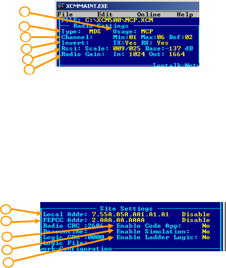
2.2.1 Radio Settings
Figure 2-8 displays the MDS Radio Settings.
Figure 2-8 XCMMAINT Software - Radio Settings
1 – Type: MDS
2 – Usage: MCP or BCP
3 – Channel: Min: 01 Max: 06 Def: 02
4 – Invert: TX: YES or NO RX: YES or NO
5 – Rssi: Scale: 009/025 Base: -137 dB
6 – Radio Gain: In: 1024 Out: 1664
Note: Default settings are in BOLD.
2.2.2 Site Settings
Figure 2-9 displays the default Site Settings for the MCP Cab Radio.
Figure 2-9 XCMMAINT Software - Site Settings
1 –Local Addr: 7.55A.A5A.AA1.A1.A1 Disable
2 – FEPCC Addr: 2.AAA.AA.AAAA Disable
3 – Enable Code App: NO
4 – Enable Simulation: NO
5 – Enable Ladder Logic: NO
Note: Default settings are in BOLD.
1
2
3
4
5
6
1
2
3
4
5
INSTALLATION AND SET UP
2-8
COM-00-09-08 REVISION A
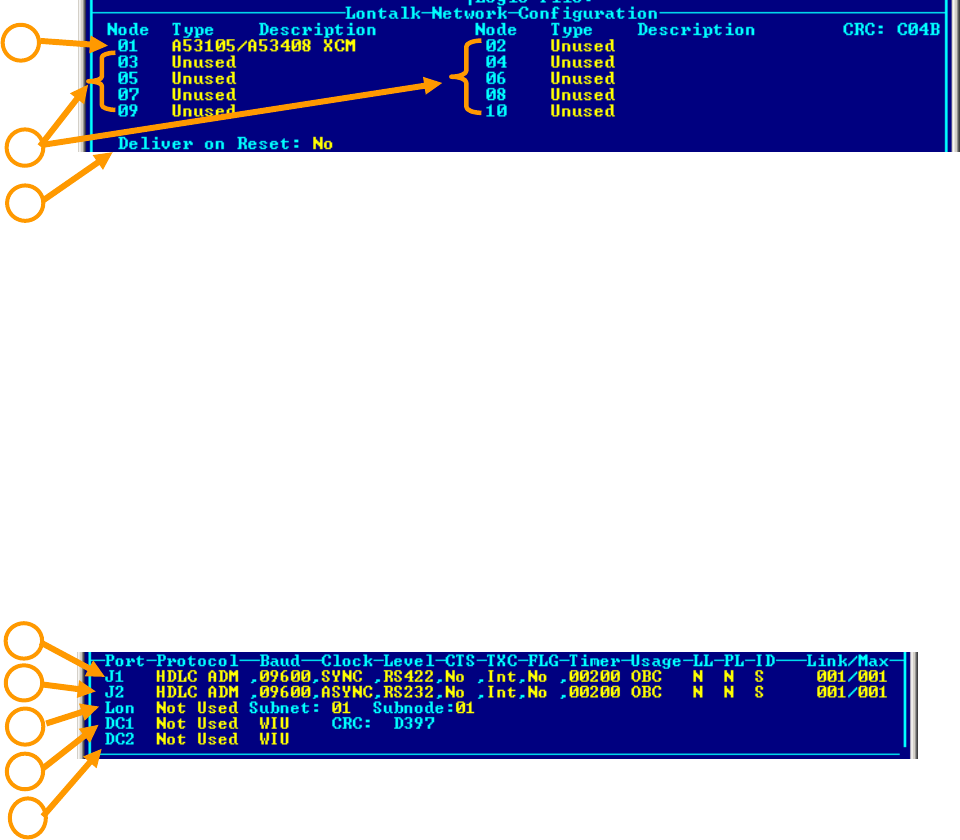
2.2.3 Lontalk® (Echelon®) Network Configuration
Figure 2-10 displays the Lontalk® (Echelon®) Network Configuration. The MCP Cab Radio uses
Node 01 only in this application.
Figure 2-10 XCMMAINT Software - Lontalk® Network Configuration
1 –Node 01: A53105/A53408 XCM
2 – Nodes 02-10: Unused
3 – Deliver on Reset: NO
Note: Default settings are in BOLD.
2.2.4 Port Information
Figure 2-11 Displays the Port information of the MCP Cab Radio. In this application only J1 and J2
are used with J1 set up in a RS-422 configuration and J2 in a RS-232 configuration.
Figure 2-11 XCMMAINT Software - Port Information
• 1 – J1: HDLC ADM, 09600, SYNC, RS-422, No, Int, No, 00200 OBC N N S 001/001
• 2 – J2: HDLC ADM, 09600, ASYNC, RS-232, No, Int, No, 00200 OBC N N S 001/001
• 3 – Lontalk®: Not Used Subnet: 01 Subnode: 01
• 4 – DC1: Not Used WIU
• 5 – DC2: Not Used WIU
Note: Default settings are in BOLD.
1
2
3
4
1
3
5
2
OPERATION
3-1
COM-00-09-08 REVISION A
SECTION 3
OPERATION
3 - OPERATION
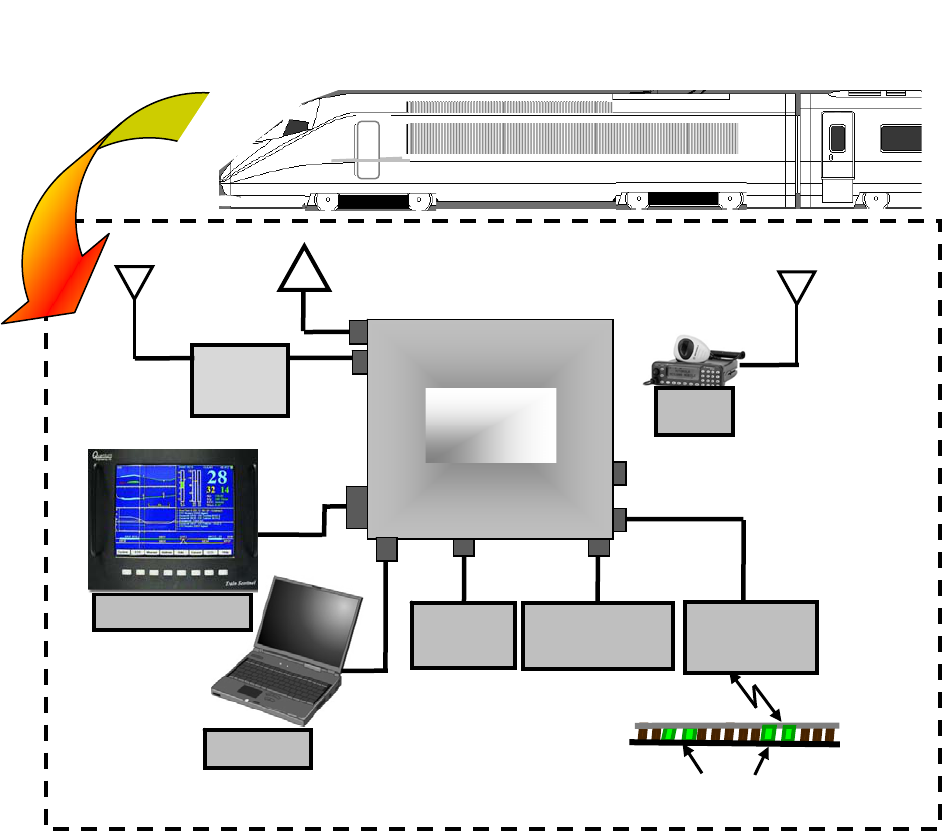
3.1 OVERVIEW
The MCP Cab Radio operates transparently in conjunction with the locomotive on-board
computer. The Cab Radio receives and transmits information between the ATCS base and wayside
stations to the locomotive on-board computer using the six ATCS UHF frequency pairs authorized
for data communications. A typical locomotive configuration is shown in Figure 3-1.
Figure 3-1 Locomotive Configuration
MCP
Radio
Locomotive
Health
Fuel
Monitor
GPS
VHF
Radio
Console Display
900 MHz 160 MHz
Terminal
On-Board
Computer
Embedded Track Transponders
Transponde
r
Receiver
OPERATION
3-2
COM-00-09-08 REVISION A
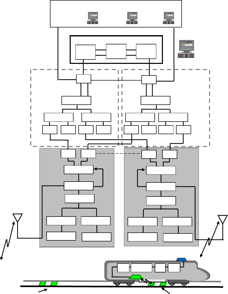
A typical network configuration is displayed in Figure 3-2, showing the control center network
connection to field wayside stations which in turn communicate with the locomotive.
Figure 3-2 Typical Network Configuration
A/B Switch
BCP
Safety
Server
Network
Server 2
Network
Server 1
TSR Serve
r
Multiplexer
Multiplexer
CETC Subsystem
CETC
Location A
CETC
Location B
CETC
Location C
Network
Management
System
DSU
HUB 2
HUB
1
Line Driver 1
A/B Switch
WCC/FDP 1
DSU
DSU
Multiplexer Multiplexer
WCC/FDP 2
DSU DSU DSU DSU DSU DSU DSU DSU
BCP
Encoder
Line Driver 2
Encoder
DSU
Line Driver Line Driver
Line Driver 1
Encoder
Line Driver 2
Encoder
Transponders
CTV PSV/UC20
A
TP
MCP
Example
Wayside
Layout
Example
Wayside
Layout
Transponders
OPERATION
3-3
COM-00-09-08 REVISION A
3.2 CAB RADIO FREQUENCY CONTROL
The locomotive cab radio generates an ATCS address and receives frequency assignments from
the MCP client via the locomotive on-board computer. The radio broadcasts data packets to
establish available links. The radio will continue this process until a link or links have been
established. In the event all links are lost, the radio reverts to the broadcast process until a link is
established. When entering another railway's territory the on-board computer will signal the MCP
client to change frequencies if applicable. Figure 3-3 displays a typical frequency change process.
Figure 3-3 Cab Radio Frequency Control
3.3 RADIO MESSAGES
The MCP Cab Radio can handle a variety of messages between the ATCS center and the
Locomotive. The radio communicates with the network using the High Level Data Link Control
(HDLC) protocol and is linked to the locomotive on-board computer using a RS-422 link.
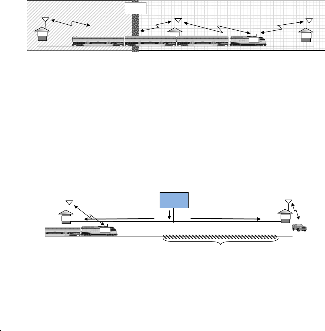
3.3.1 Temporary Speed Restriction (TSR)
Temporary Speed Restriction (TSR) orders are sent from the base station and received by the MCP
can sent to the on-board computer. Data derived from GPS, transponders, and wayside station
established the locomotive location, thus enabling the on-board computer to advise the
locomotive's location in reference to the TSR boundaries. Figure 3-4 displays a TSR example.
Figure 3-4 Temporary Speed Restriction Example
TX 935.9375 MHz
RX 896.9375 MHz
CH2
BCP
BCP BCP
MCP
FREQUENCY
CHANGE
TX 896.9375 MHz
RX 935.9375 MHz
CH2
TX 935.9375 MHz
RX 896.9375 MHz
CH2
TX 935.9875 MHz
RX 896.9875 MHz
CH3
MOW
TS
R
Broadcast
BCP BCP
MCP
TEMPORARY SPEED RESTRICTION BOUNDARY
A
TCS
DISPATCH
CENTER
OPERATION
3-4
COM-00-09-08 REVISION A
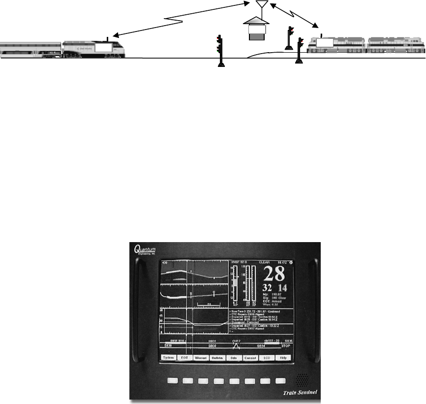
3.3.2 Interlocking Status
Interlocking Status is sent from the base station and received by the MCP is sent to the on-board
computer. In some cases (i.e. dark territory), remote control interlocks can be controlled from the
locomotive cab. The MCP can serve as a primary or secondary communication source. Figure 3-5
displays an example of an interlock status exchange.
Figure 3-5 Interlocking Status
3.4 POSITIVE TRAIN CONTROL
As Positive Train Control systems develop, the MCP Cab Radio will play a key role. Data gathered
from wayside sources can be combined with other data sources and displayed on the locomotive
console.
Figure 3-6 PTC Display
BCP
MCP
INTERLOCK
MCP

SERVICE
4-1
COM-00-09-08 REVISION A
SECTION 4
SERVICE
4 - SERVICE
4.1 OVERVIEW
Routine service of the MCP Cab Radio is performed by qualified personnel as specified by
standard railroad or agency standards and procedures. The Logic Board information is accessed
via the 9-pin Diagnostic Port on the face of the Cab Radio unit. Diagnostic testing of the UHF
Radio is performed using the RJ-11 Radio Diagnostic port and Radio Configuration software for
the MDS UHF Radio. The Logic Board is accessible via a service panel on the side of the unit.
NOTE
Testing and service of the radio component must be
performed by qualified technical personnel as
defined in FCC Rules, Part 90 and Part 101.
4.2 MCP DIAGNOSTICS
Diagnostic of the MCP are performed using the User Diagnostic port which is a DB-9 connector
mounted on the front panel of the unit connected to a PC or Laptop computer using the Safetran
XCMMAINT software.
4.2.1 Opening XCMMAINT
Open the XCMMAINT software by opening the XCMMAINT.EXE file. The opening screen in Figure
4-1 will appear.
Figure 4-1 Opening XCMMAINT
SERVICE
4-2
COM-00-09-08 REVISION A
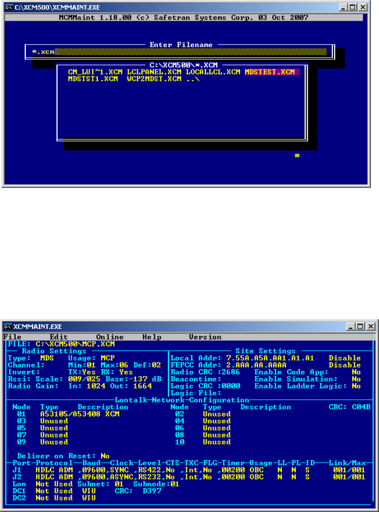
4.2.2 Selecting File
Hit the ENTER key to display the available configuration files. If a Codeplug file has been saved for
the unit being tested use the ARROW KEYS to highlight the appropriate file. Hit the ENTER key to
load the file. If the codeplug file is not available or to view a programmed unit press ESC to enter
the default screen. Section 4.2.4.4 details how to read the Codeplug information in the unit.
Figure 4-2 Filename Select
4.2.3 Unit Configuration
The opening screen will display the configuration of the MCP. Changes should not be initiated
unless the unit is being updated our reconfigured. Changing these settings may render the unit
inoperable.
Figure 4-3 Opening Screen
SERVICE
4-3
COM-00-09-08 REVISION A
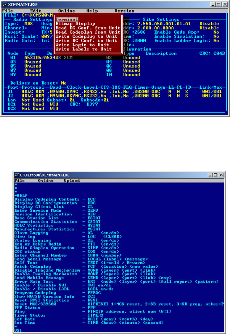
4.2.4 Terminal Mode
The terminal mode opens a utility application to review various logs as well as make desired
changes to the logic board and view basic radio functions. Type ALT-O, the drop menu will
appear, highlight TERMINAL and press ENTER to start the terminal mode.
Figure 4-4 Terminal Mode
The Terminal mode opens with a blank screen. Hit the ENTER key and an asterisk (*) will display.
Type HELP for a list of available commands as displayed in Figure 4-5.
Figure 4-5 Terminal Mode - Help Screen
SERVICE
4-4
COM-00-09-08 REVISION A
4.2.4.1 Terminal Mode Commands
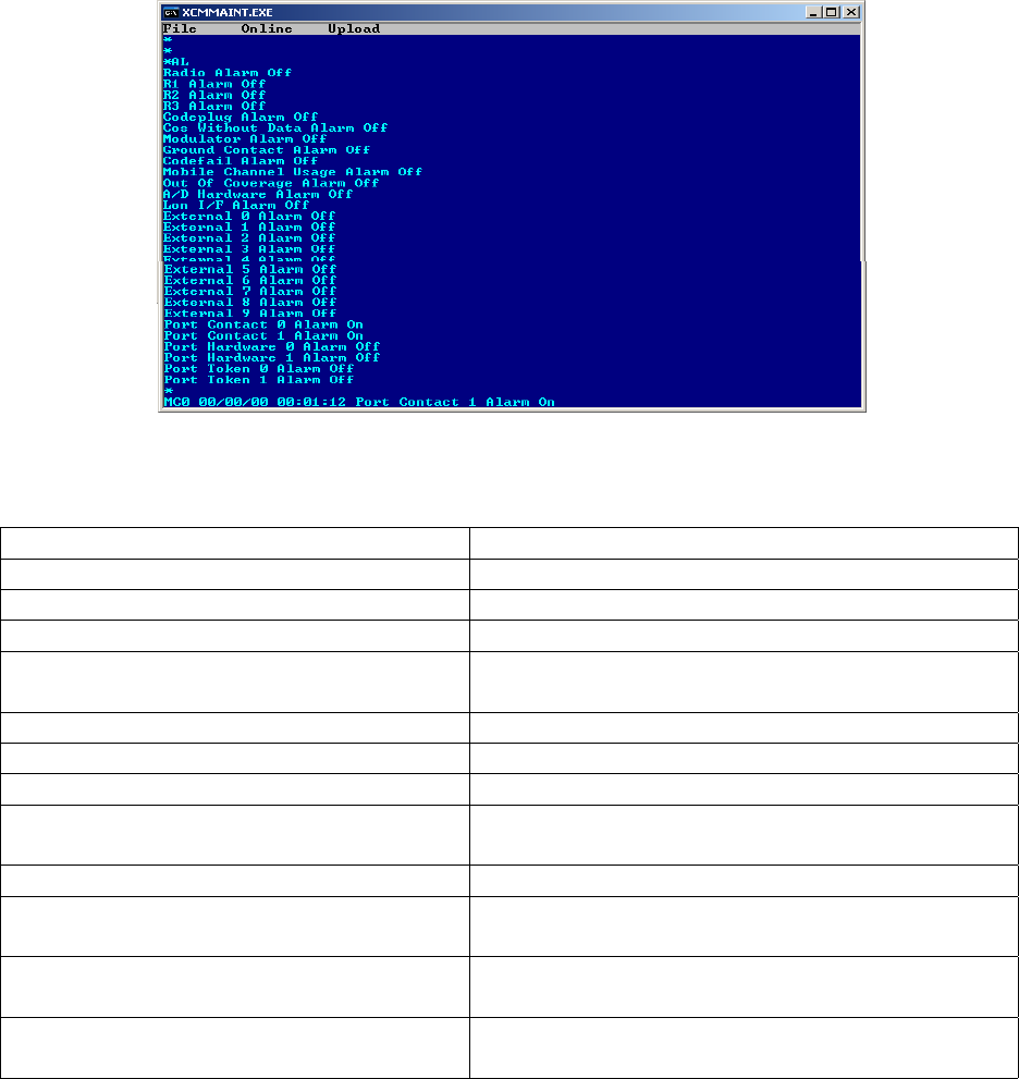
4.2.4.1.1 AL en/ds - Alarm Logging
Alarm logging is initially enabled. When the command is first entered, all alarms and their
respective states are displayed. After alarm logging is enabled, any subsequent changes to any of
the alarms are displayed individually as they occur. If the command is re-entered to enable
logging, the display reflects the present state of the alarms.
Figure 4-6 Display Alarms
The following alarms are monitored by the function:
RADIO ALARM The entire radio has failed
RADIO PA ALARM Radio power amplifier failure
RADIO POWER ALARM Radio is operating on battery power
CODEPLUG ALARM Codeplug CRC comparison failure or write failure
COS WITHOUT DATA ALARM The RF channel has been asserted without data for
longer than the allowable time limit
MODULATOR ALARM The RF modulator has failed
GROUND CONTACT ALARM Ground contact was not established at start up
ANALOG TO DIGITAL CONVERTER ALARM
The A/D converter selftest has failed
MOBILE CHANNEL USEAGE ALARM Generated
by the BCP when a MCP violates channel
usage restrictions
OUT OF COVERAGE ALARM Contact with ground network has been lost
EXTERNAL ALARM External alarm (0 through 3) generated by parallel
input lines
PORT CONTACT ALARM Alarm (0 through 3) indicating loss of contact with
client at the remote end of the link
PORT HARDWARE FAIL Alarm (0 through 3) indicating hardware failure of a
client link port
SERVICE
4-5
COM-00-09-08 REVISION A
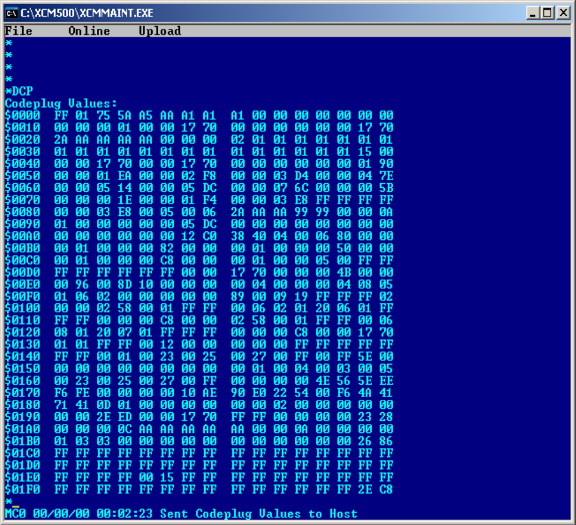
4.2.4.1.2 DCP - Display Codeplug
Enter DCP and press ENTER to display codeplug values currently programmed into the unit. The
contents of the codeplug are displayed as bytes in hex format. The leftmost column is the location
of the first value on that line. The locations of the other values on that line are offset from the
first position.
Figure 4-7 Display Codeplug Contents
SERVICE
4-6
COM-00-09-08 REVISION A
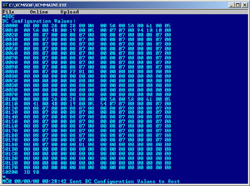
4.2.4.1.3 DDC - DC Configuration Values
Enter DDC and press ENTER to display the DC Configuration of the unit. The DC Configuration is
displayed as bytes in hex format. The leftmost column is the location of the first value on that
line. The locations of the other values on that line are offset from the first position.
Figure 4-8 Display DC Configuration
SERVICE
4-7
COM-00-09-08 REVISION A
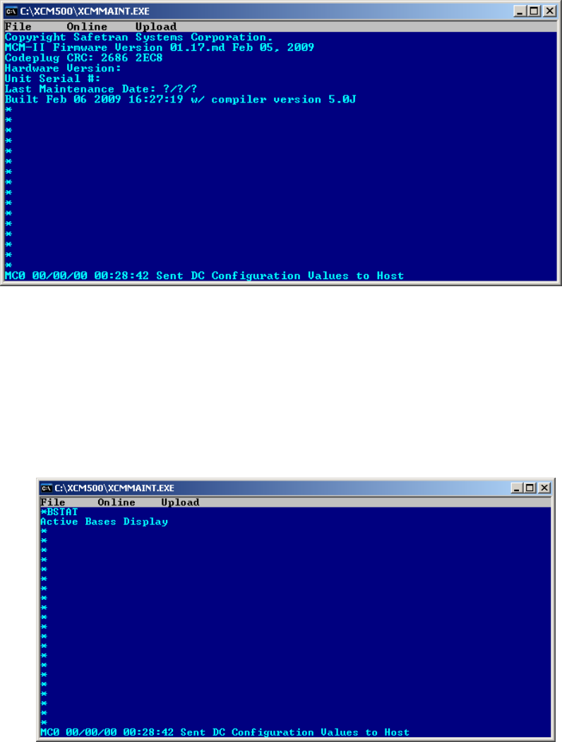
4.2.4.1.4 VER - Firmware Hardware Codeplug Version Information
Type VER and press ENTER to view the Version information of the installed codeplug.
Figure 4-9 Version Identification
4.2.4.1.5 BSTAT - Active Base Station Status
The BSTAT command will display active base stations heard by the MCP. Stations are removed
from the list after a period of inactivity.
Figure 4-10 Base Station List

SERVICE
4-8
COM-00-09-08 REVISION A
4.2.4.1.6 CSTAT - Communication Statistics
The CSTAT command opens a screen with communications statistics.
Figure 4-11 Communication Statistics
The following data is displayed on the Communications Statistics screen:
MINUTES OF OPERATION The number of the unit has been operational
TOTAL RECEIVED The number of datagrams received on the respective
logical channels 0 through F.
TOTAL SENT The number of datagrams sent on the logical channels
0 through F.
TOTAL RETRIES The number of datagrams retransmitted on the even
logical channels
TOTAL FAILED The number of datagrams that were not successfully
sent on the even logical channels
TOTAL ACK ONLY The number of ACK only datagram that were sent on
the even logical channels
CONTACT FAILURE The number of contact failures that have occurred on
client port 0, client port 1, and the RF link respectively
FLOW CONTROL The number of times flow control was entered, the
number of times recovery procedures were performed,
and the number of times re-recovery procedures were
performed
SSI The current value in the SSI for the last datagram
received, the maximum SSI value is the highest
received, and the minimum is the lowest SSI received
SERVICE
4-9
COM-00-09-08 REVISION A
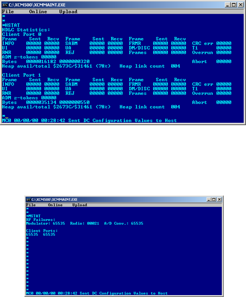
4.2.4.1.7 HSTAT - HDLC Statistics
Type HSTAT to display the HDLC information as shown in Figure 4-12
Figure 4-12 HDLC Statistics
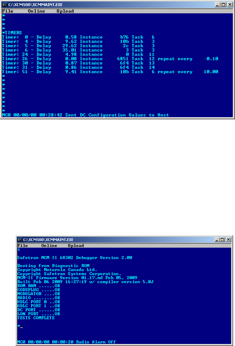
4.2.4.1.8 MSTAT - Manufacturer Statistics
The MSTAT command opens a screen that lists manufacturer statistics.
Figure 4-13 Manufacturer Statistics

SERVICE
4-10
COM-00-09-08 REVISION A
4.2.4.1.9 LOG - Display Log
Type LOG command to view the System Log. Use the <F> key to move forward, <S> key to go to
the start of the log, and the <E> key to shift to the end of the log. Press the ESC key to exit the
log and return to the main screen.
Figure 4-14 View Log
4.2.4.1.10 SL - Status Log
Type SL command and press ENTER. The status logging is initially disabled. When the command is
first entered to enable status logging (SL en), the status summary is displayed. After status logging
is enabled, any subsequent state changes are displayed as they occur. If the command is re-
entered to enable status logging, the summary reflects the present status of the MCP. The SL ds
command disables the status log.
Figure 4-15 Status Log
SERVICE
4-11
COM-00-09-08 REVISION A
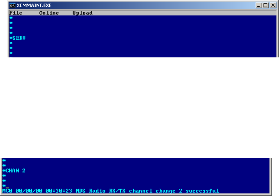
4.2.4.1.11 TIMERS - Display Timer Configurations
Type the TIMERS command and press ENTER to list the current configuration of the logic timers.
Figure 4-16 Timer Status
4.2.4.1.12 TEST restart - MCP Self-Test
The TEST command resets the MCP and performs a series of diagnostic tests before returning to
operational status. The TEST command has two arguments:
0 (warm) - Perform the self-tests while the MCP remains operational
1 (cold) - Resets the MCP and the power-up sequence is performed including
the self-tests.
Figure 4-17 MCP Self-test
SERVICE
4-12
COM-00-09-08 REVISION A
4.2.4.1.13 SERV - Service Command
The SERV (Service) command activates certain functions and disables others for service purposes.
The MCP performs functions controlled by the testport; all other functions are disabled. Once in
the service mode, it is necessary to reset the MCP to return to the operational mode. Resetting of
the MCP is accomplished using the TEST command. The following functions are activated with the
MCP in the Service Mode.
• CHAN - Change channel number
• ERT - Perform error rate test
• PTT en/ds - Key/De-key radio
• SIMP en/ds - Enable/disable simplex mode
To place the MCP Cab Radio in the Service (SERV) mode type SERV and press ENTER as shown in
Figure 4-18.
Figure 4-18 Service (SERV) Mode
4.2.4.1.14 CHAN - Change Channel (SERV Mode Only)
The CHAN command changes channels between the programmed channel pairs stored in the
radio. Type the command followed by the desired channel number (e.g. CHAN 2) and the screen
will acknowledge the channel change as shown in Figure 4-19
Figure 4-19 Change RX/TX Channel
SERVICE
4-13
COM-00-09-08 REVISION A
The ATCS frequency pairs have been programmed into the radio codeplug as follows:
CH. No. Base to Mobile (RX) Frequency Mobile to Base (TX) Frequency
1 935.8875 MHz 896.8875 MHz
2 935.9375 MHz 896.9375 MHz
3 935.9875 MHz 896.9875 MHz
4 936.8875 MHz 897.8875 MHz
5 936.9375 MHz 897.9375 MHz
6 936.9875 MHz 897.9875 MHz
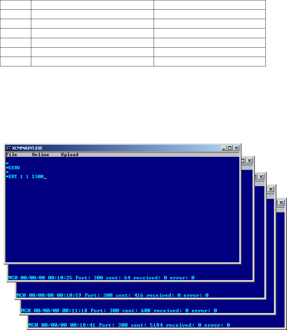
4.2.4.1.15 ERT - Error Rate Test (SERV Mode Only)
The Error Rate Test (ERT command) allows communication links to be tested and error rate
figures to be calculated. The unit must be in the service (SERV) mode to operate. Type SERV and
press ENTER to activate the service mode.
Figure 4-20 Error Rate Test Screens

SERVICE
4-14
COM-00-09-08 REVISION A
The ERT command has the following arguments:
Mode - Type of Loopback Mode
1 = open (NO) loopback
2 = digital loopback
3 = analog loopback
4 = open loop with RTS asserted (for wireline modem only)
Layer - Allows user to specify layer
1 = physical layer - allows a bit error rate test to be done
(For RF Channel Only)
2 = datalink layer - allows message error rate testing to be done
Port - Allows user to specify port number
$100 = Client Port 0 (wireline modem port on BCP)
$101 = Client Port 1 (spare port on BCP)
$300 = RF Channel
Pattern - Byte pattern to send (hex or ASCII). If not defined, a default pattern
is used.
The results will be displayed at the bottom of the screen as shown in Figure 4-20. The definitions
below detail the test results displayed.
PORT - The port for which these results apply
SENT - The number of patterns generated by this unit
RECEIVED - The number of patterns correctly received by this unit
ERROR - The number of patterns received that do not match the
generated pattern; except for RF Channel (port $300) physical
layer (layer 1) ERT commands, where this represents the
number of bit errors.
BER - The ratio of the total error bit count over the total received bit
count (i.e., [total bit errors] / [total bits received]). This
calculation applies to RF channel physical layer (layer 1) ERT
commands only
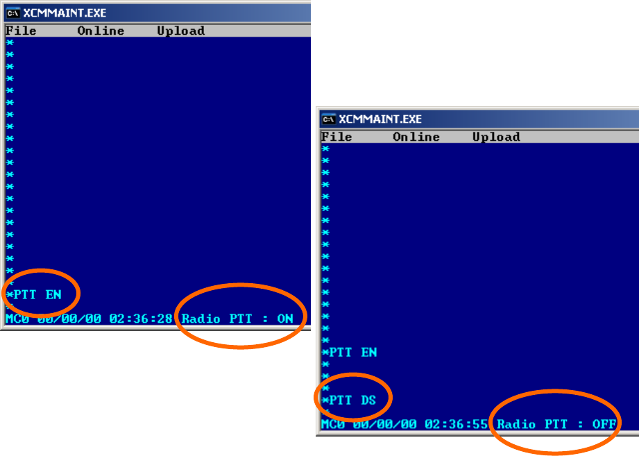
SERVICE
4-15
COM-00-09-08 REVISION A
4.2.4.1.16 PTT en/ds - Push To Talk (SERV Mode Only)
The PTT command allows the user to key and dekey the radio. To verify the result of the PTT
command, Status Logging (SL command) must be enabled. If the radio is already in the requested
state, the command is ignored. The command remains in effect until explicitly changed. The result
is displayed on the bottom of the screen as shown in Figure 4-21. The MCP transmitter time-out
timer will automatically de-key the radio if allowed to expire. To rekey the MCP in this case, the
radio must be first de-keyed using the de-key command (PTT ds), then the radio can be keyed
using the key command (PTT en).
Figure 4-21 PTT - Push To Talk Command
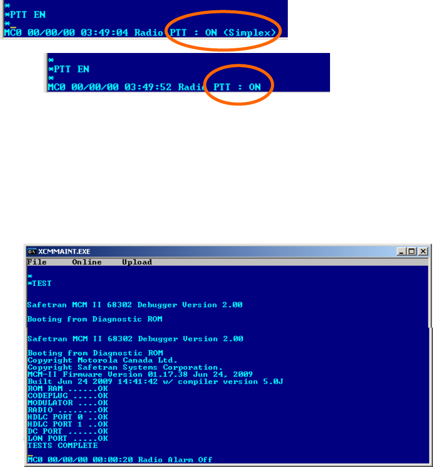
SERVICE
4-16
COM-00-09-08 REVISION A
4.2.4.1.17 SIMP en/ds - Simplex Command (SERV Mode Only)
The SIMP command enables or disables the MCP radio simplex mode of operation. In the normal
mode, one frequency is used for transmit and another frequency is used for receive. In the
simplex mode, the normal mode receive frequency is also used for transmit. The radio is initially
in the normal mode. When the MCP is in the out-of-coverage (fallback) mode, it will revert to
simplex mode operation to allow direct RF-user to RF-user communication. There is no direct
indication that this command has been executed. However, the simplex/normal mode status may
be monitored by executing the Status Logging (SL) command. When the radio is keyed, simplex
operation is indicated in the radio PTT state field as displayed in Figure 4-22.
Figure 4-22 Simplex and Normal Mode Displays
4.2.4.1.18 Exit SERV Mode
Once in the service mode, it is necessary to reset the MCP to return to the operational mode.
Resetting of the MCP is accomplished using the TEST command. Type TEST and press ENTER the
MCP will perform a cold start and return to normal operation.
Figure 4-23 Exit SERV Mode
SIMPLEX MODE
NORMAL MODE
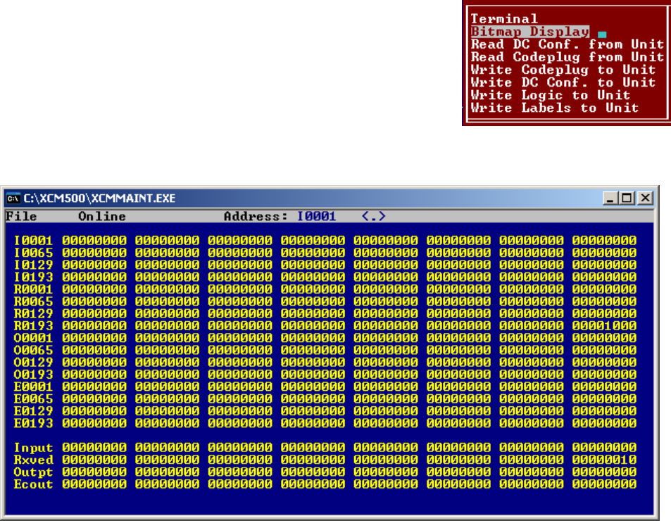
SERVICE
4-17
COM-00-09-08 REVISION A
4.2.4.2 Bit Map Display
This entry displays the Bitmap screen, figure 6-10, which is an
online dynamic display of the logic state of any physical inputs or
outputs associated with the WCP CPU II via ladder logic. The
logic state of all internal bit fields are displayed as well. When
properly configured I/O modules are installed on the local
Echelon® LAN, the current state of their inputs and outputs can
be determined using this screen.
Figure 4-24 Bitmap Display
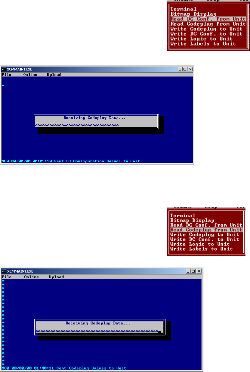
SERVICE
4-18
COM-00-09-08 REVISION A
4.2.4.3 Read DC Configuration from Unit
By selecting this function and pressing ENTER, the configuration of the
DC port of the MCP is read. The Receiving data popup box will
display briefly as the data is read. The main edit screen will be
updated to reflect the configuration data that is read.
Figure 4-25 Read DC Configuration from Unit
4.2.4.4 Read Codeplug from Unit
By selecting this function and pressing ENTER, the Codeplug portion of
the MCP configuration data is read. This is a 512-byte data array that
stores all the user-modifiable MCP configuration information. The
Receiving data popup box (see above) will display briefly as the data
is read. The main edit screen is updated to reflect the codeplug data
that is read.
Figure 4-26 Read Codeplug from Unit
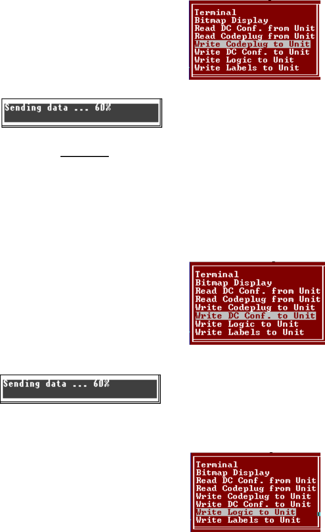
SERVICE
4-19
COM-00-09-08 REVISION A
4.2.4.5 Upload Codeplug to Unit
The sending data popup box will display briefly as codeplug data is
written. By selecting this function and pressing ENTER, all the
configuration data appearing on the main edit screen will be written
to the WCP CPU II non-volatile memory.
CAUTION
EXISTING CODEPLUG DATA IN THE WCP CPU WILL
BE OVERWRITTEN AND IRRETRIEVABLY LOST.
4.2.4.6 Upload DC Configuration to Unit
By selecting this function and pressing ENTER, the DC configuration
data on the main edit screen (DC1) will be written to MCP.
The Sending data popup box may display briefly while the data is
being uploaded.
4.2.4.7 Upload Logic to Unit
This function uploads compiled ladder logic to the MCP if the
following conditions are met:
1. Appropriate ladder logic has been compiled
2. The name of the logic file generated has been entered on the main edit screen (in the Site
Settings section). The file extension is omitted.
After the upload sequence is complete, the WCP CPU II calculates a CRC value for the ladder logic.
If this CRC value does not match the CRC embedded in the logic file, the process aborts with the
WCP CPU II unchanged.
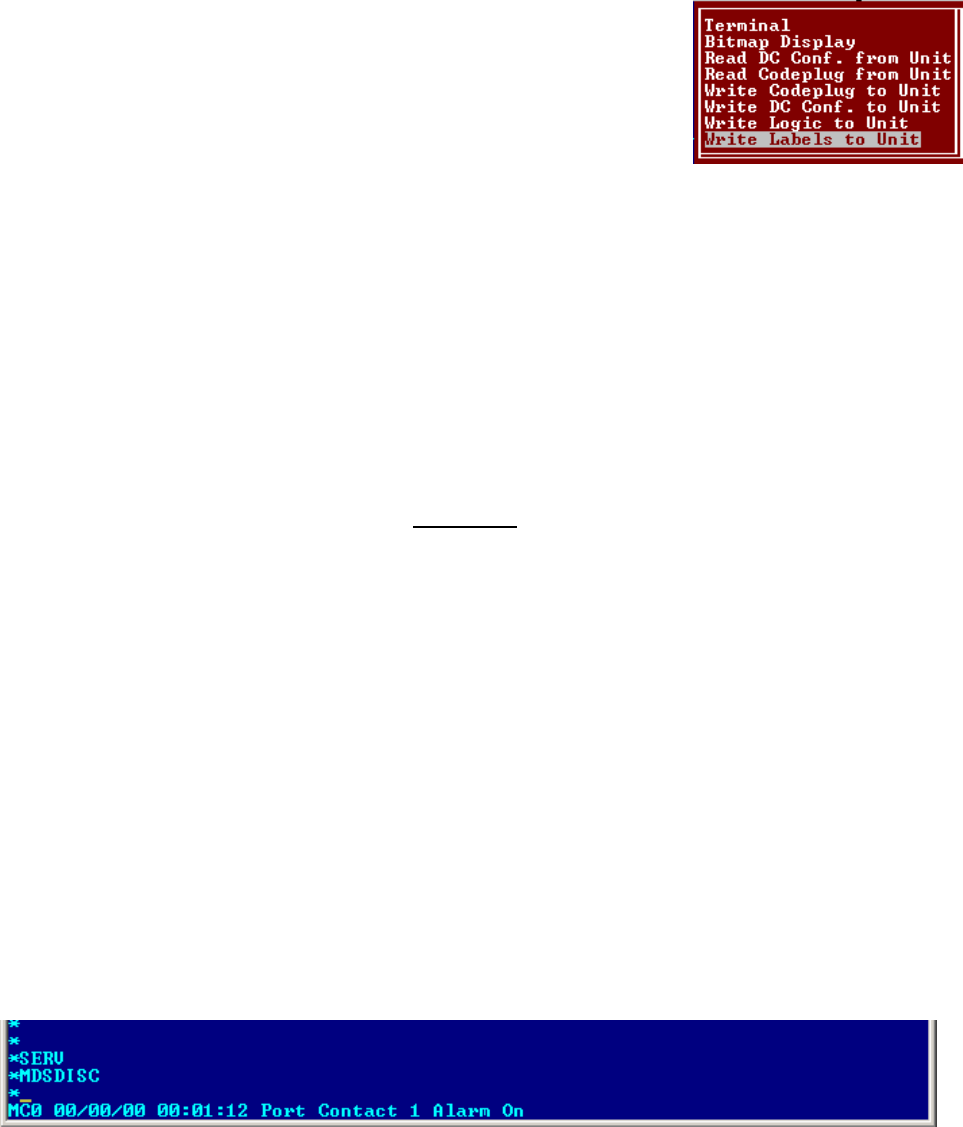
SERVICE
4-20
COM-00-09-08 REVISION A
4.2.4.8 Upload Labels to Unit
By selecting this function and pressing ENTER, the tokenized label file
associated with the ladder logic is uploaded to the WCP CPU II. The
conditions for uploading are the same as for the logic upload
described above. The label file and the logic file are generated by the
logic compiler and will have the same base filename (with different
extensions). As a result, it is only necessary to specify the base
filename in the Logic File field on the main edit screen.
4.2.4.9 Radio Diagnostics
The MCP Cab Radio is equipped with a RJ-11 Radio Diagnostics port on the front panel. This port
communicates with the MDS Radio directly and enables configuration of the radio as well as
provide current configuration information. Radio Diagnostics requires the use of MDS Radio
Configuration software (Part Number: 03-3156A01, Rev 2.4.0 or later) and a DB-9 to RJ-11 cable as
described in Section 1.3.5 of this manual.
WARNING
RADIO DIAGNOSTICS MUST BE PERFORMED BY
QUALIFIED PERSONNEL IN ACCORDANCE WITH
FCC RULES AND REGULATIONS. FAILURE TO
COMPLY MAY RESULT INTERFERENCE TO OTHER
EQUIPMENT AND MAY VOID USERS AUTHORITY
TO OPERATE THIS DEVICE.
4.2.4.9.1 Activation of Radio Diagnostics Port
In normal operation the RJ-11 port is not active. To activate the Radio Diagnostic port it is
necessary to place the MCP Cab Radio in the service mode using the XCMMAINT software. Type
SERV to and press ENTER to activate the Service Mode. To activate the Radio Diagnostic Port type
MDSDISC and press ENTER as shown in Figure 4-27.
Figure 4-27 Activation of Radio Diagnostics Port
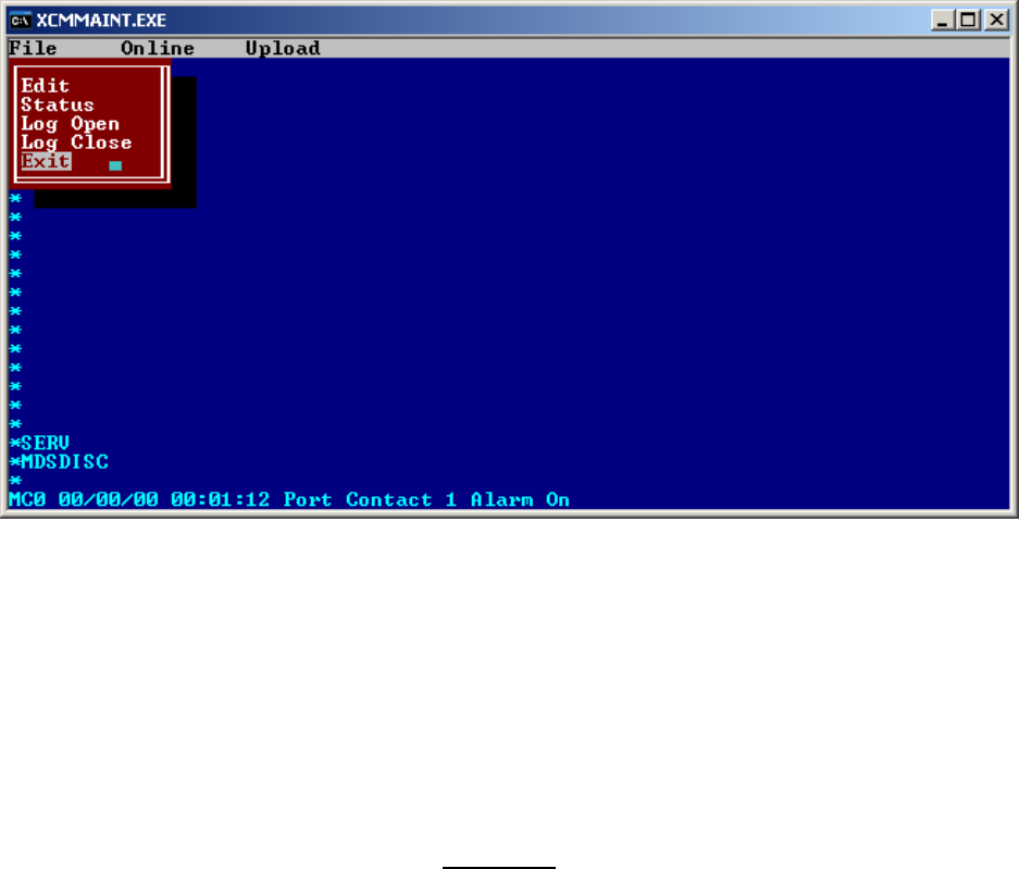
SERVICE
4-21
COM-00-09-08 REVISION A
It is necessary to exit the XCMMAINT program before the Radio Diagnostic port will become
active. Note it is necessary to exit the XCMMAINT program by type ALT-F, the pull down menu
will appear. Highlight EXIT using the ARROW keys or a mouse and press ENTER as shown in Figure
4-28.
Figure 4-28 Exit XCMMAINT
4.2.4.10 Radio Configuration Software
The MDS Radio Configuration Software is provided on CD media and it will be required to install
the software on the PC being used to configure the radio.
WARNING
RADIO CONFIGURATION MUST BE PERFORMED
BY QUALIFIED PERSONNEL IN ACCORDANCE
WITH FCC RULES AND REGULATIONS. FAILURE
TO COMPLY MAY RESULT INTERFERENCE TO
OTHER EQUIPMENT AND MAY VOID USERS
AUTHORITY TO OPERATE THIS DEVICE. PRIOR TO
ALTERING ANY CONFIGURATION PARAMETERS
ENSURE ANY CHANGES ARE COMPATIBLE WITH
THIS APPLICATION.
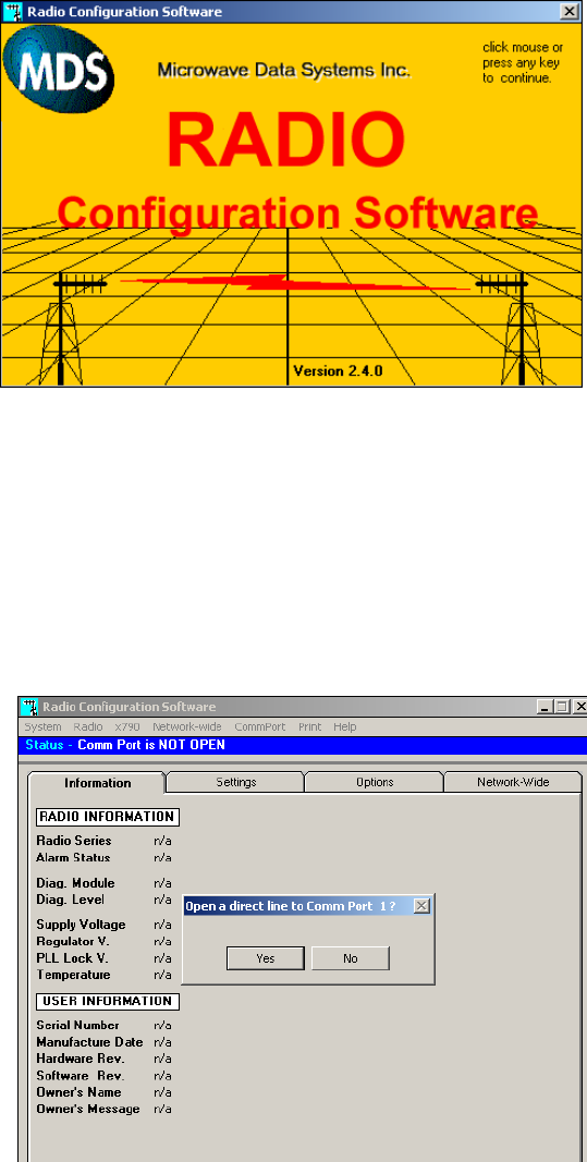
SERVICE
4-22
COM-00-09-08 REVISION A
4.2.4.10.1 Opening Radio Configuration Software
With the software installed, open the application. The opening screen will appear as shown in
Figure 4-29.
Figure 4-29 Configuration Software - Opening Screen
4.2.4.10.2 Open Com Port
The software must open the communication port between the computer and the radio and read
this information from the radio. Click YES on the pop-up window to open a direct line to the radio
as shown in
Figure 4-30 Configuration Software - Open Comm Port
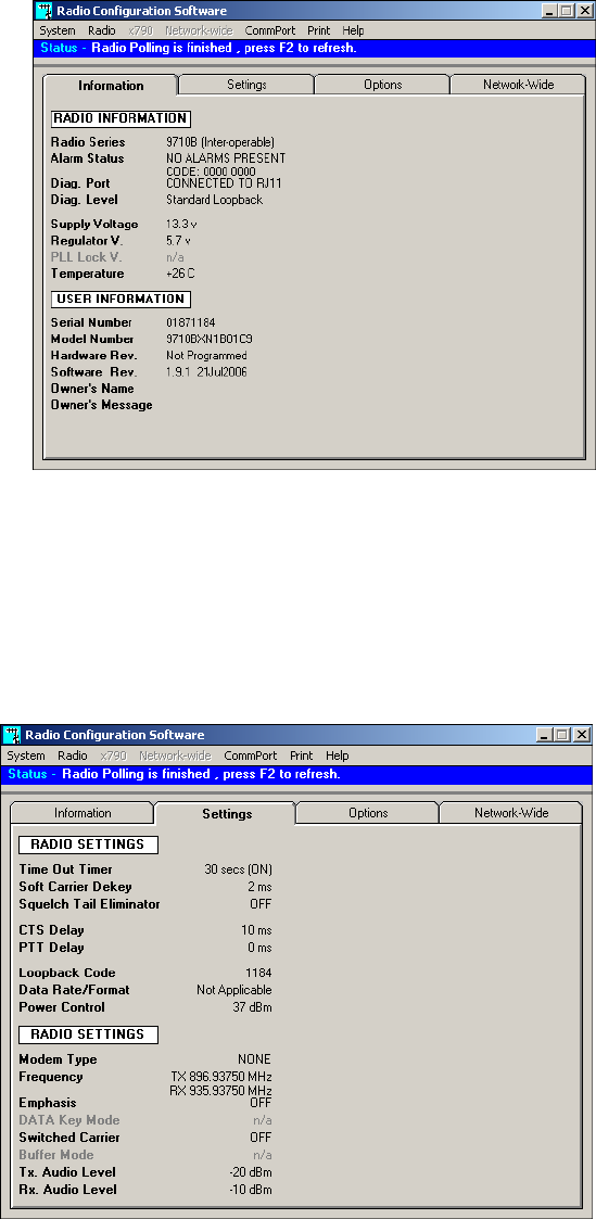
SERVICE
4-23
COM-00-09-08 REVISION A
4.2.4.10.3 Radio Information
The Information tab displays the Radio Information and User Information as shown below.
Figure 4-31 Configuration Software - Radio Information Tab
4.2.4.10.4 Radio Settings
The Settings tab displays the current radio settings programmed into the radio.
Figure 4-32 Configuration Software - Radio Settings Tab

SERVICE
4-24
COM-00-09-08 REVISION A
4.2.4.10.5 Options
The Options tab displays the authorized radio options available.
Figure 4-33 Configuration Software - Radio Options
4.2.4.10.6 Main Menu
Using the the task bar click on RADIO to bring up the Main Menu.
Figure 4-34 Configuration Software - Main Menu
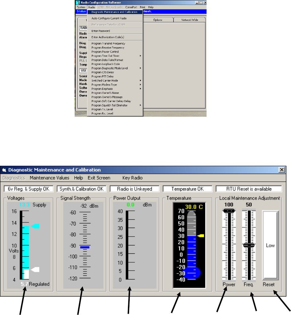
SERVICE
4-25
COM-00-09-08 REVISION A
4.2.4.10.7 Diagnostic Maintenance and Calibration
Click on Diagnostic Maintenance and Calibration selection from the Main Menu as shown in Figure
4-35.
Figure 4-35 Configuration Software - Main Menu - Diag. Maint. & Calib.
The following window opens displaying current radio status.
Figure 4-36 Configuration Software - Diagnostic Maintenance and Calibration
Transceiver
Voltages
Received Signal
Strength Indicator
(RSSI)
Power
Output
Indicator
RTU
Reset
Temperature
Indicator
Transmit
Power
Adjustment
Frequency
Adjustment
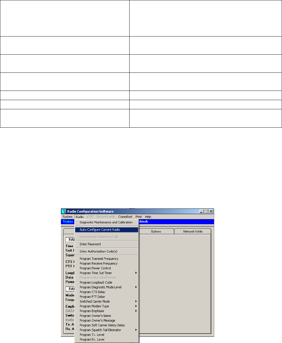
SERVICE
4-26
COM-00-09-08 REVISION A
The Indicators and Controls on the Diagnostic Maintenance and Calibration window are as follows:
Transceiver Voltages This area shows the level of two voltages inside the
transceiver. The input source voltage and the
regulated radio voltage used by the transceiver
components.
Received Signal Strength Indicator
(RSSI)
This area shows the approximate strength (in dBm)
of the signal being received.
Power Output Indicator This area shows the power output (in dBm) of the
transceiver when the unit is in the transmit mode.
Temperature Indicator This thermometer displays the internal temperature
of the radio in degrees Celsius.
Transmit Power Adjustment This slider adjusts the output of the radio.
Frequency Adjustment This slider fine-adjusts the TX-RX frequencies.
RTU Reset Used with the Remote Terminal Unit (RTU). Click
the button to set pin 15 High or Low.
4.2.4.10.8 Auto-Configure
Click on RADIO in the task bar and bring up the Main Menu. Highlight Auto-Configure Current
Radio to bring up the Auto-Configure window.
Figure 4-37 Configuration Software - Auto-Configure Current Radio
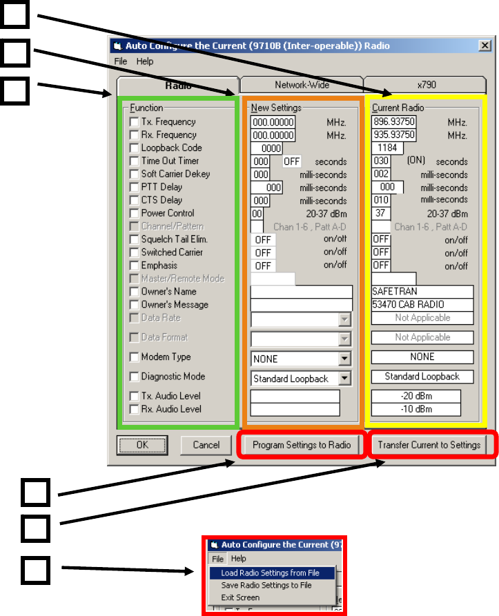
SERVICE
4-27
COM-00-09-08 REVISION A
The Auto-Configure window will appear and starts the utility. This feature allows management,
storage, uploading, and downloading of transceiver parameter files. New settings may be entered
in to the New Settings column. Pressing the Program Settings To Radio button will transfer the
information to the radio. Pressing the Cancel button will abort the procedure. Click on the
Transfer Current to Settings button will populate the New Settings column with the Current Radio
Settings
Figure 4-38 Configuration Software - Auto Configure Utility
1
6
2
4
5
3

SERVICE
4-28
COM-00-09-08 REVISION A
The Auto Configure Utility components are as follows:
Current Radio - This column lists the current radio configuration as read by the utility
New Settings - This Column is used to enter new settings desired for the radio.
Function - This column has a check box for each configurable function. To configure a
function, check the box and enter the new setting in the New Settings Column.
Program Settings to Radio - This button sends selected new settings to the radio.
Transfer Current to Settings - This button copies and sends all of the current data in the
Current Radio column to the New Settings column.
File Drop Menu - The File Drop Menu has the following three functions:
• Load Radio Settings from File - This selection opens a standard
dialog box to open a transceiver paramenter file that has been
stored on the computer. Notice the default suffix name is .RFP
which is an abbreviation for Radio Parameter File.
• Save Radio Settings to File - This selection opens a standard
dialog box to save a transceiver parameter file that has to be stored
on the computer. Notice the default filename suffix is RPF which is
an abbreviation for Radio Parameter File.
• Exit Screen - This function exits the Auto Configure Utility and
returns control of the software to the Main Window.
Auto Configure Programming Example
Refer to Figure 4-39 for screen examples. To program a new transmit frequency check the box [1]
to the left of Tx Frequency in the Function column. Enter the desired transmit frequency in the Tx
Frequency box [2] in the New Settings Column. Press the Program Settings to Radio button. The
button will indicate programming and the parameter box will turn yellow [2]. In the event the
parameter did not successfully program, the parameter box in the new settings column [3] will
turn red. Check the parameter and verify it is within an acceptable range for the radio. In this
example the frequency was entered wrong and is out of the range of the radio and has alarmed
by turning the box red. Re-enter the parameter and press the Program Settings to Radio button.
The button will indicate programming and the parameter box [2] will turn yellow. If the
programming was successful the parameter box [4] will turn green. Click the OK button or use the
File drop menu to exit the utility.
1
2
3
4
5
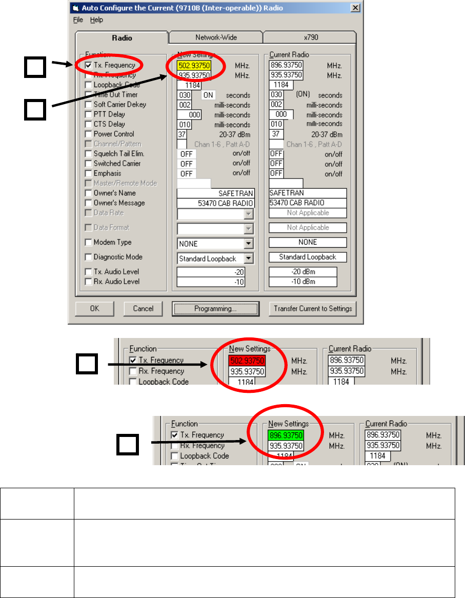
SERVICE
4-29
COM-00-09-08 REVISION A
YELLOW A parameter box turns yellow during the transfer process.
RED A parameter box that turns red indicates the parameter has not successfully
transferred to the radio. Verify the parameter has been entered correctly
and is within the proper limits.
GREEN A parameter box that turns green indicates the transfer process has been
successful.
Figure 4-39 Configuration Software - Auto Configure Programming Example
1
3
2
4

SERVICE
4-30
COM-00-09-08 REVISION A
4.2.4.10.9 Programming Transmit Frequency
Using the Radio Main Menu select the Program Transmit Frequency entry as shown in Figure 4-40.
A dialog box will appear with the current frequency listed and a box to enter the new frequency.
Enter the new frequency and click the Program button. An error window will appear in the event
the entry is not valid.
Figure 4-40 Configuration Software - Program Transmit Frequency
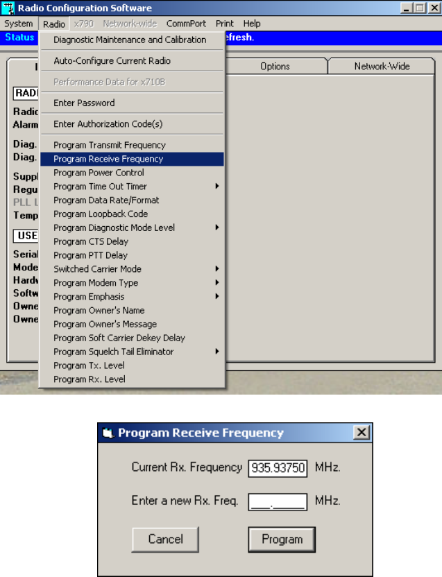
SERVICE
4-31
COM-00-09-08 REVISION A
4.2.4.10.10 Programming a Receive Frequency
Using the Radio Main Menu select the Program Receive Frequency entry as shown in Figure 4-41.
A dialog box will appear with the current frequency listed and a box to enter the new frequency.
Enter the new frequency and click the Program button. An error window will appear in the event
the entry is not valid.
Figure 4-41 Configuration Software - Program Receive Frequency
4.2.4.10.11 Setting Transmit Power Level
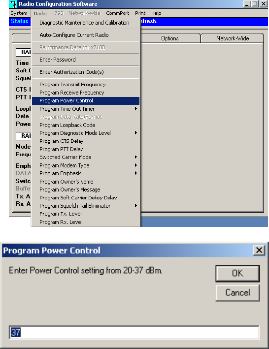
SERVICE
4-32
COM-00-09-08 REVISION A
Using the Radio Main Menu select the Program Power Control entry as shown in Figure 4-40. A
dialog box will appear, enter the desired power level and press the OK button. The default setting
for this application is full power (37 dBm).
Figure 4-42 Configuration Software - Setting Transmit Power Level
4.2.4.10.12 Program Time-out Timer Delay
This selection allows the Time-Out Timer (TOT) delay to be programmed
4.2.4.10.13 Program Loopback Code
This selection allows the loopback code to be programmed. Default in this application is 1184.
SERVICE
4-33
COM-00-09-08 REVISION A
4.2.4.10.14 Program Diagnostic Mode Level
This menu item allows selection of the appropriate level of diagnostics support. The transceiver
must be configured for the diagnostics mode selected. This application uses Standard Loopback
for the default setting.
4.2.4.10.15 Program CTS Delay
This selection allows the CTS (Clear to Send) delay to be programmed. Default for this application
is 10 milliseconds.
4.2.4.10.16 Program PTT Delay
This selection allows the PTT (Push to Talk) delay to be programmed. The default for this
application is set at 0.
4.2.4.10.17 Switched Carrier Mode
This setting selects the Switched Carrier Mode. Default in this application is Off.
4.2.4.10.18 Program Modem Type
The selection allows selection of the modem type. Default in this application is None.
4.2.4.10.19 Program Emphasis
This menu item selects Emphasis. This application has the default set to Off.
4.2.4.10.20 Program Owner's Name
This selection allows a name (up to 27 characters) to be programmed for identification purposes.
4.2.4.10.21 Program Owner's Message
This selection allows a 27 character message to be programmed.
4.2.4.10.22 Program Soft Carrier Dekey Delay
This selection allows the Soft Carrier Dekey Delay (SCD) duration to be programmed. Default in
this application is 2 milliseconds.
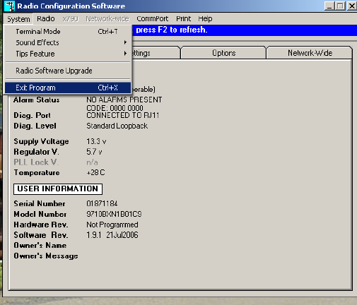
SERVICE
4-34
COM-00-09-08 REVISION A
4.2.4.10.23 Program Squelch Tail Eliminator
On and OFF pop-up choices allow the Squelch Tail Eliminator (STE) to be enabled (ON) or
disabled (OFF). Default for this application is Disabled (OFF).
4.2.4.10.24 Program TX Level
The TX Audio Level sets the input level (in dBm) on the TX audio input line for analog
functionality. Choosing a fixed input level means that the TX audio signal will be scaled to the
optimum peak frequency deviation over the air. This means if a TXLEVEL is set to -10 dBm and the
input signal is actually -20 dBm, then the modulated signal will have a low peak deviation. The
AUTO mode will check the input TX audio signal's peaks and scale the signal accordingly so that
the peak deviation is the desired value. Default in this application is -17 dBm.
4.2.4.10.25 Program RX Level
The RX Audio Level sets the output level (in dBm) on the RX audio output line. Default in this
application is -5 dBm.
4.2.4.10.26 Closing MDS Configuration Software
To close the MDS Configuration Software, click on the System pull-down menu. Select End
Program and click the selection. Allow the program to close the diagnostic port connections.
Power down and restart the Cab Radio to restore normal operation.
Figure 4-43 Closing the MDS Configuration Software

COM-00-09-08 REVISION A
NOTES

Safetran Systems Corporation
2400 Nelson Miller Parkway
Louisville, Kentucky 40223
(502) 618-8800
Safetran Systems Corporation
California Division
10655 7th Street
Rancho Cucamonga, California 91730
(909) 532-5300