Inventec TPC-I024-WCT Wireless charging device User Manual Hardware Reference Guide
Inventec Corporation Wireless charging device Hardware Reference Guide
UserManual.wiki
>
Inventec
>
TPC-I024-WCT User Manual
>
User Manual
Contents
1.
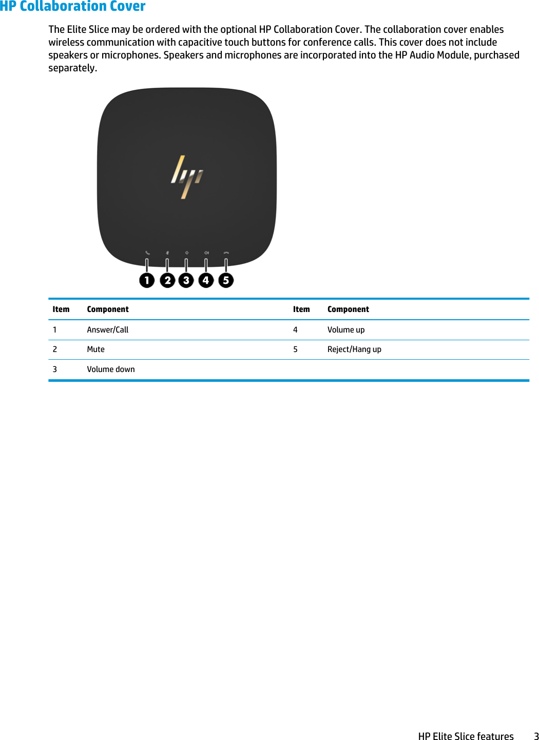
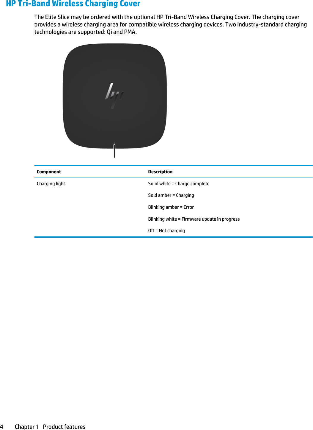
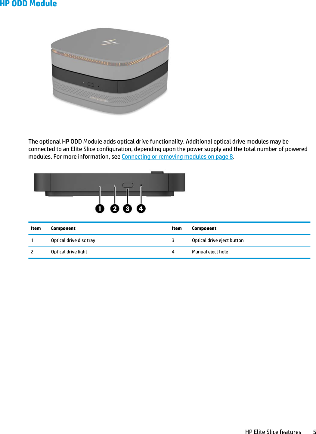
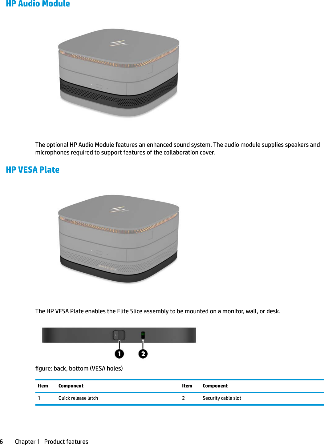
User Manual
2.
User Manual (statements)
User Manual
Navigation menu
Upload a User Manual
Namespaces
Wiki Guide
HTML
PDF
Info
Views
User Manual
Discussion / Help
Navigation