Inventec TPC-I024-WCT Wireless charging device User Manual Hardware Reference Guide
Inventec Corporation Wireless charging device Hardware Reference Guide
Inventec >
Contents
- 1. User Manual
- 2. User Manual (statements)
User Manual

Hardware Reference Guide
HP Elite Slice
© Copyright 2016 HP Development Company,
L.P.
The information contained herein is subject to
change without notice. The only warranties for
HP products and services are set forth in the
express warranty statements accompanying
such products and services. Nothing herein
should be construed as constituting an
additional warranty. HP shall not be liable for
technical or editorial errors or omissions
contained herein.
First Edition: June 2016
Document part number: 900063-001
Product Notice
This guide describes features that are common
to most models. Some features may not be
available on your computer.
Software terms
By installing, copying, downloading, or
otherwise using any software product
preinstalled on this computer, you agree to be
bound by the terms of the HP End User License
Agreement (EULA). If you do not accept these
license terms, your sole remedy is to return the
entire unused product (hardware and software)
within 14 days for a refund subject to the
refund policy of your seller.
For any further information or to request a full
refund of the computer, please contact your
seller.

About This Book
This guide provides basic information for upgrading the HP Elite Slice.
WARNING! Text set o in this manner indicates that failure to follow directions could result in bodily harm or
loss of life.
CAUTION: Text set o in this manner indicates that failure to follow directions could result in damage to
equipment or loss of information.
NOTE: Text set o in this manner provides important supplemental information.
iii
iv About This Book

Table of contents
1 Product features ........................................................................................................................................... 1
HP Elite Slice features ............................................................................................................................................ 1
HP Elite Slice ........................................................................................................................................ 1
HP Collaboration Cover ........................................................................................................................ 3
HP Tri-Band Wireless Charging Cover .................................................................................................. 4
HP ODD Module .................................................................................................................................... 5
HP Audio Module .................................................................................................................................. 6
HP VESA Plate ...................................................................................................................................... 6
Serial number location .......................................................................................................................................... 7
2 Setup ............................................................................................................................................................ 8
Connecting or removing modules .......................................................................................................................... 8
Connecting modules ............................................................................................................................ 8
Removing modules ............................................................................................................................ 11
Connecting power ................................................................................................................................................ 11
Attaching the Elite Slice to a mounting device .................................................................................................... 12
Installing a security cable .................................................................................................................................... 13
Synchronizing the optional wireless keyboard and mouse ................................................................................ 14
3 Hardware upgrades ...................................................................................................................................... 16
Serviceability features ......................................................................................................................................... 16
Warnings and cautions ........................................................................................................................................ 16
Removing and replacing the access panel .......................................................................................................... 17
Removing the access panel ............................................................................................................... 17
Replacing the access panel ............................................................................................................... 17
Locating internal components ............................................................................................................................ 18
Upgrading system memory ................................................................................................................................. 19
Memory module specications ......................................................................................................... 19
Populating memory module slots .................................................................................................... 20
Installing system memory modules ................................................................................................. 21
Removing and replacing a hard drive .................................................................................................................. 23
v
Appendix A Electrostatic discharge .................................................................................................................. 25
Preventing electrostatic damage ........................................................................................................................ 25
Grounding methods ............................................................................................................................................. 25
Appendix B Computer operating guidelines, routine care and shipping preparation ............................................. 26
Computer operating guidelines and routine care ............................................................................................... 26
Shipping preparation ........................................................................................................................................... 27
Appendix C Accessibility ................................................................................................................................. 28
Supported assistive technologies ....................................................................................................................... 28
Contacting support .............................................................................................................................................. 28
Index ............................................................................................................................................................. 29
vi
1 Product features
HP Elite Slice features
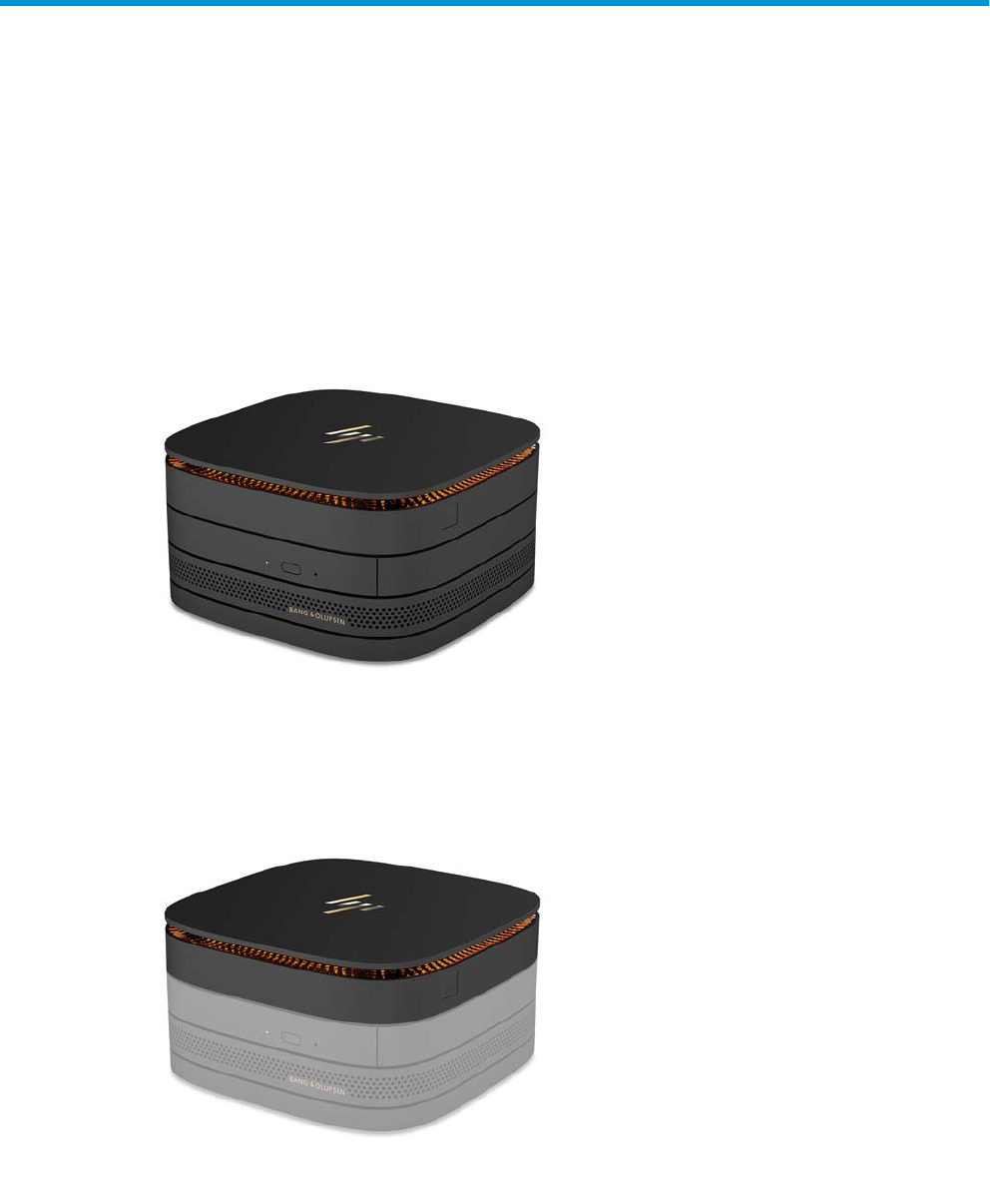
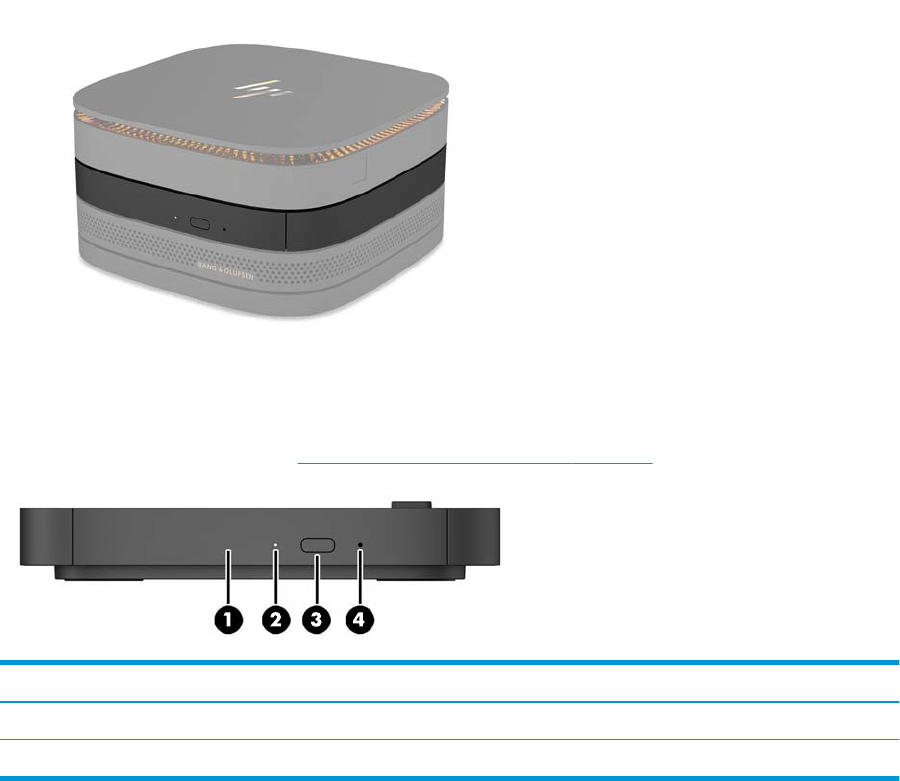
HP Elite Slice
The Elite Slice is the base module, the single essential module. The Elite Slice features an optional full-
ngerprint reader: instead of swiping your nger across the reader, you press your nger on the reader. This
reader is more accurate than the swipe readers.
HP Elite Slice features 1
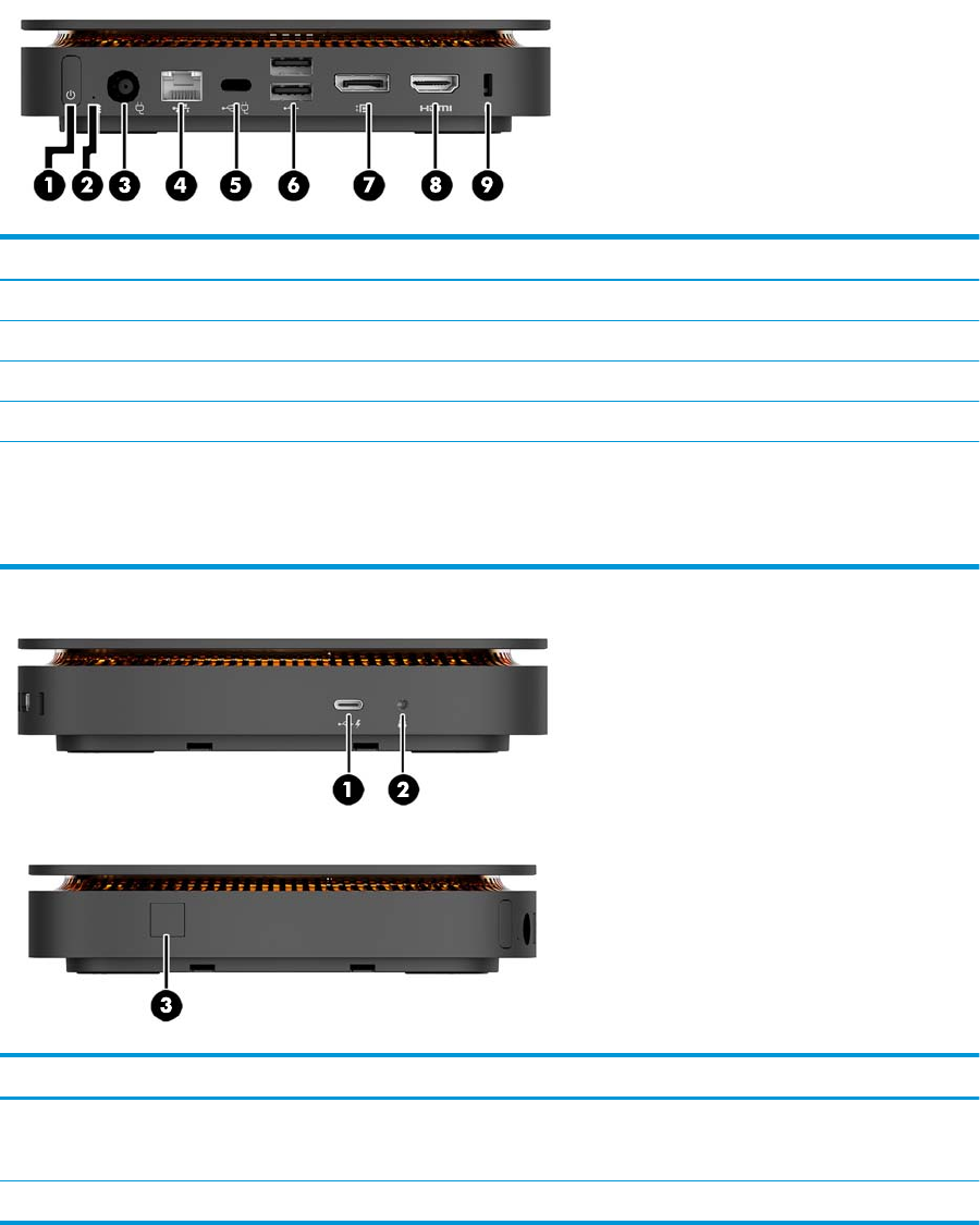
Item Component Item Component
1 Power button 6 USB ports (2)
2 Drive light 7 Dual-Mode DisplayPort (D++)
3 Power connector 8 HDMI port
4 RJ-45 (network) jack 9 Security cable slot
5 USB Type-C port
60 W input, DisplayPort
15 W output
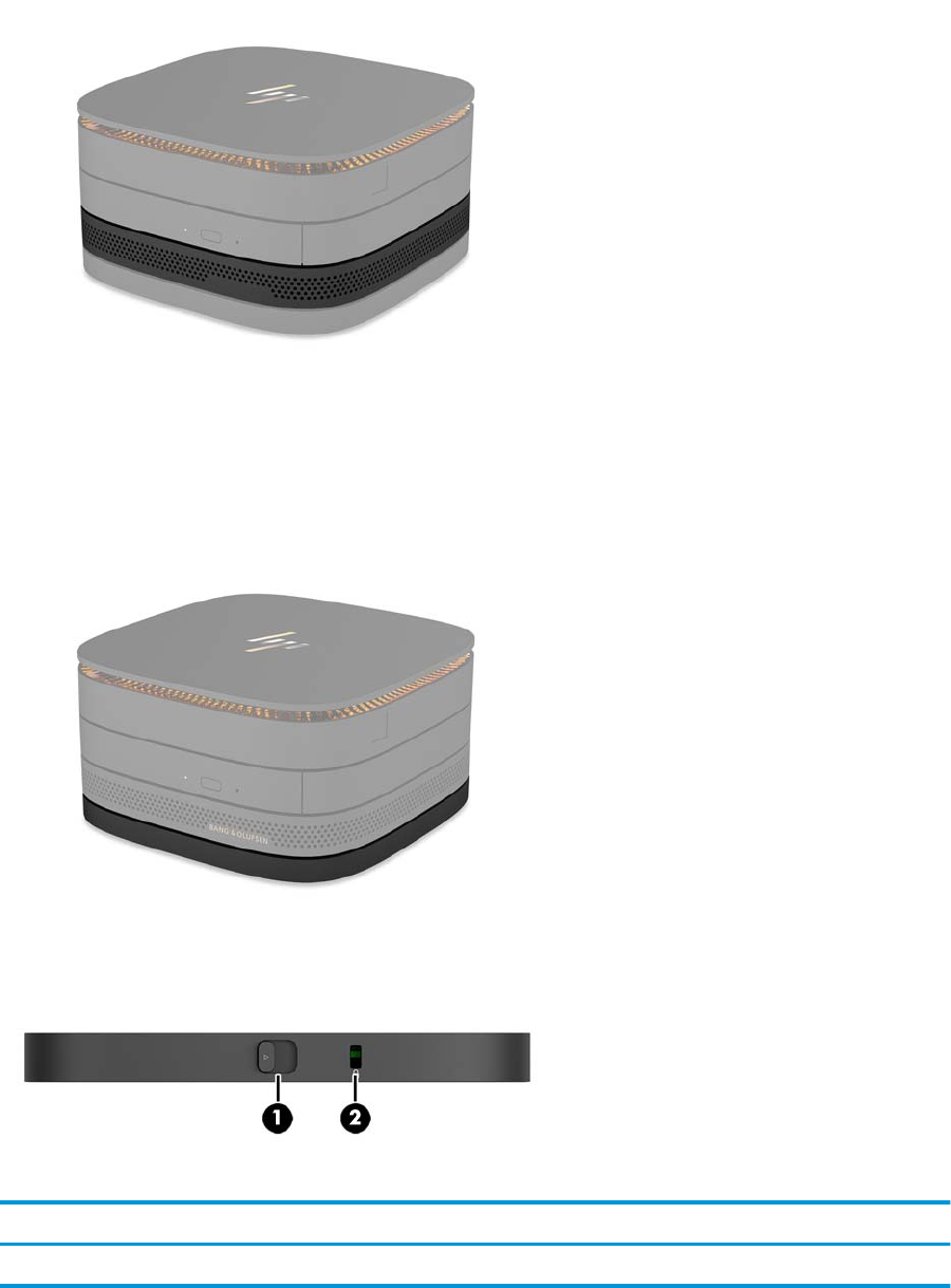
Item Component Item Component
1 USB Type-C port
15 W output
3Full-ngerprint reader (optional)
2 Universal audio jack
2 Chapter 1 Product features
HP Collaboration Cover
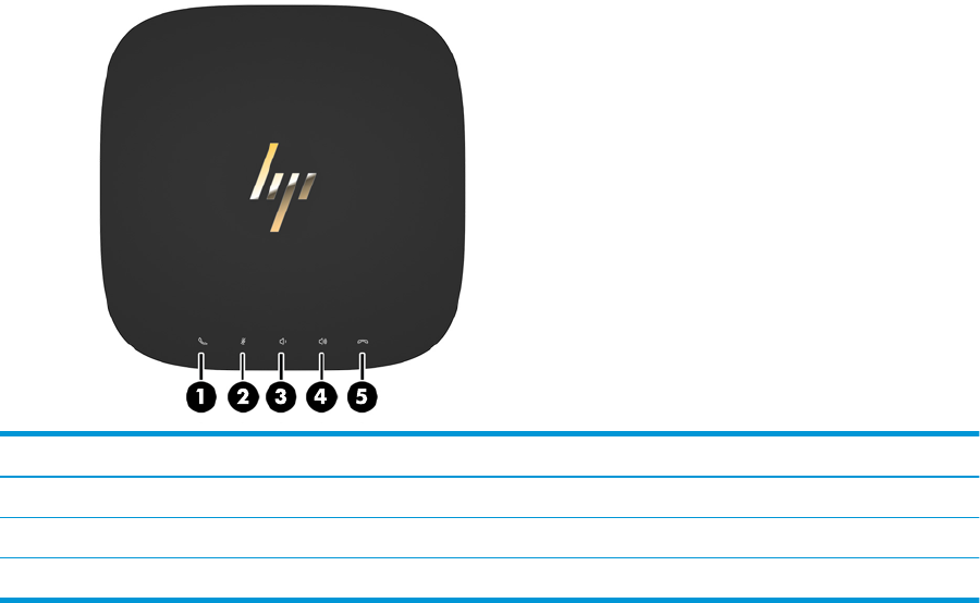
The Elite Slice may be ordered with the optional HP Collaboration Cover. The collaboration cover enables
wireless communication with capacitive touch buttons for conference calls. This cover does not include
speakers or microphones. Speakers and microphones are incorporated into the HP Audio Module, purchased
separately.
Item Component Item Component
1 Answer/Call 4 Volume up
2 Mute 5 Reject/Hang up
3 Volume down
HP Elite Slice features 3
HP Tri-Band Wireless Charging Cover
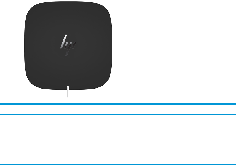
The Elite Slice may be ordered with the optional HP Tri-Band Wireless Charging Cover. The charging cover
provides a wireless charging area for compatible wireless charging devices. Two industry-standard charging
technologies are supported: Qi and PMA.
Component Description
Charging light Solid white = Charge complete
Sold amber = Charging
Blinking amber = Error
Blinking white = Firmware update in progress
O = Not charging
4 Chapter 1 Product features
HP ODD Module
The optional HP ODD Module adds optical drive functionality. Additional optical drive modules may be
connected to an Elite Slice conguration, depending upon the power supply and the total number of powered
modules. For more information, see Connecting or removing modules on page 8.
Item Component Item Component
1 Optical drive disc tray 3 Optical drive eject button
2 Optical drive light 4 Manual eject hole
HP Elite Slice features 5
HP Audio Module
The optional HP Audio Module features an enhanced sound system. The audio module supplies speakers and
microphones required to support features of the collaboration cover.
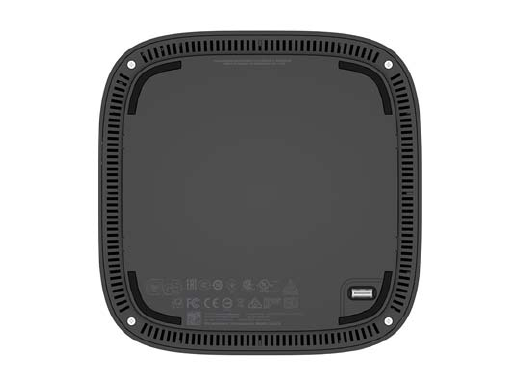
HP VESA Plate
The HP VESA Plate enables the Elite Slice assembly to be mounted on a monitor, wall, or desk.
gure: back, bottom (VESA holes)
Item Component Item Component
1 Quick release latch 2 Security cable slot
6 Chapter 1 Product features
Serial number location
Each computer has a unique serial number and a product ID number laser-etched on the bottom of the Elite
Slice. A copy of these labels is inside the case. Keep these numbers available for use when contacting support
for assistance.
Serial number location 7

2 Setup
Connecting or removing modules
Three types of modules may be connected to the Elite Slice: optical drive module, audio module, and VESA
plate. Modules should be attached to the base module in the following order:
●HP ODD Modules
●HP Audio Module
●HP VESA Plate
The optical drive module and the audio module are powered modules. Only one audio module may be
connected to the Elite Slice. Depending on the AC adapter, however, you may be able to connect multiple
optical drive modules.
NOTE: Check the label on the AC adapter to verify the power supplied.
●A 90 W AC adapter (which ships with the HP Tri-Band Wireless Charging Cover) allows up to four powered
modules to be connected to the Elite Slice:
—Up to three optical drive modules and one audio module
– or –
—Up to four optical drive modules (and no audio module)
●A 65 W AC adapter allows up two powered modules to be connected to the Elite Slice:
—One optical drive module and one audio module
– or –
—Up to two optical drive modules (and no audio module)
Connecting modules
CAUTION: Before connecting modules, turn o the Elite Slice and disconnect it from any power source.
Modules cannot be “hot-plugged” or “hot-swapped.”
1. Remove/disengage the security cable, if one is attached.
2. Remove all removable media, such as USB ash drives.
3. Turn o the Elite Slice properly through the operating system, and then turn o any external devices.
8 Chapter 2 Setup
4. Disconnect the power cord from the Elite Slice and disconnect any external devices.
5. If the VESA plate is connected, slide the quick release latch to the unlocked position and remove the
VESA plate.
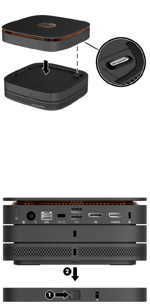
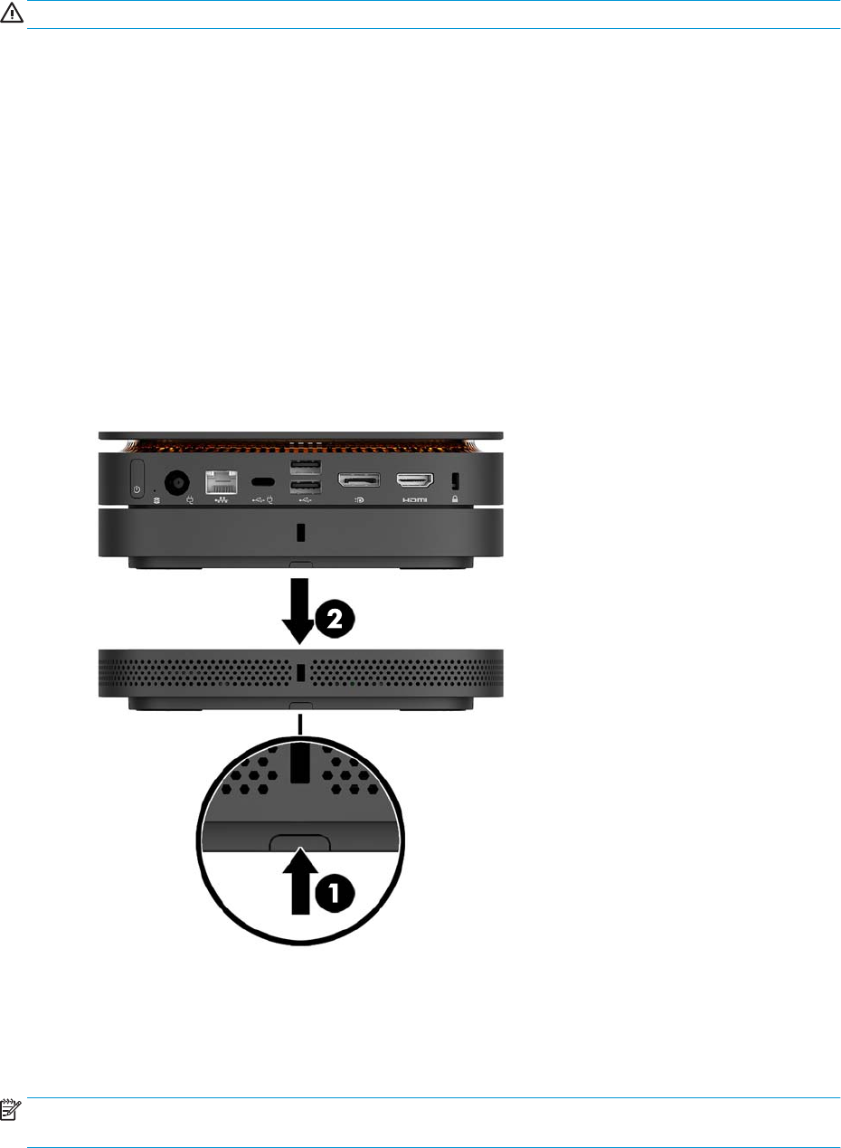
6. Align the module connection port on the underside of the Elite Slice with the module expansion
connector on another module and press the Elite Slice down rmly.
You should hear a quiet click when the modules lock together. Each module locks into place and hides
the release latch of the module above it.
Repeat until all modules have been connected.
7. Slide the quick release latch on the VESA plate (1) to the unlocked position. Position the connected
modules over the VESA plate.
The VESA plate does not have an module expansion connector. Be sure that the ports of Elite Slice and
the quick release latch and security cable slot of the VESA plate are all on the same side.
8. Press the modules (2) down onto the VESA plate.
Connecting or removing modules 9
9. Slide the quick release latch on the back of the VESA plate to the locked position to lock all modules
together.
CAUTION: There are four tabs in the VESA plate. When you position the Elite Slice conguration
correctly onto the VESA plate and slide the quick release latch to the locked position, the four tabs lock
the VESA plate to the Elite Slice assembly. If the VESA plate is not correctly oriented, the quick release
latch cannot be moved to the locked position and the modules are not secured.
10. Install a security cable in the VESA plate security cable slot to prevent the quick release latch from being
unlocked and the modules from being separated.
NOTE: The security cable is designed to act as a deterrent, but it may not prevent the computer from
being mishandled or stolen.
10 Chapter 2 Setup
Removing modules
CAUTION: Before disconnecting modules, turn o the Elite Slice and disconnect it from any power source.
Modules cannot be “hot-plugged” or “hot-swapped.”
Modules must be removed one at a time, starting at the bottom. Removing the bottom module exposes the
release latch of the module above it.
1. Remove/disengage the security cable, if one is attached.
2. Remove all removable media, such as USB ash drives.
3. Turn o the Elite Slice properly through the operating system, and then turn o any external devices.
4. Disconnect the power cord from the Elite Slice and disconnect any external devices.
5. If the VESA plate is connected, slide the quick release latch on the back of the VESA plate to the unlocked
position and lift the module stack o the VESA plate.
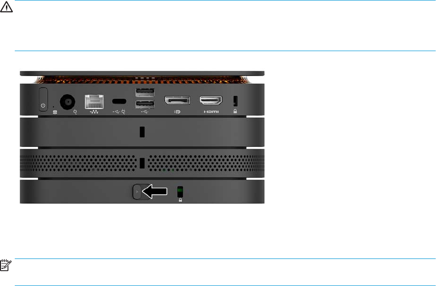
6. Beginning at the bottom, remove additional modules by pressing the release latch (1) on the underside
of each module until it releases the module (2) above it.
Connecting power
The Elite Slice can be connected to a powered port on an HP monitor or it can be connected to an AC outlet
using the HP adapter that shipped with the Elite Slice. Power sources not obtained from HP will be rejected.
NOTE: Under certain power-loading conditions, some USB ports may be temporarily disabled to meet
product safety regulations.
Connecting power 11
To connect to an AC outlet:
1. Connect the power cord to the AC adapter and the AC outlet.
IMPORTANT: When connecting the Elite Slice to an AC outlet, you must use the HP adapter that
shipped with the Elite Slice.
2. Connect the AC adapter to the power connector on the rear of the Elite Slice.
If you have an HP monitor with a charging port that can supply at least 60 W, you may connect the Elite Slice
to the monitor instead of an AC outlet.
1. Disconnect Slice from AC power.
NOTE: If the Elite Slice is connected to both a powered port and an AC outlet, the Elite Slice will use the
AC power.
2. Connect one end of a US Type-C cable (purchased separately) to a rear USB Type-C port on the Elite Slice.
3. Connect the other end of the cable to a charging port on an HP monitor.
Attaching the Elite Slice to a mounting device
If the VESA plate is connected, the Elite Slice can be attached to a monitor, wall, or desk in either of two
mounting positions:
●Vertical
●Horizontal with all cables attached to the rear of the computer and hanging straight down
To mount the Elite Slice:
1. Connect all modules except the VESA plate.
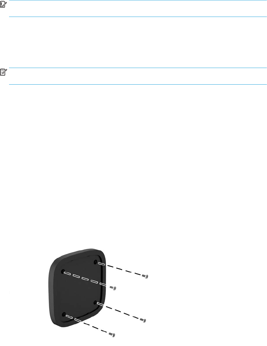
2. Use the four screws provided with the VESA plate to attach the VESA plate to the monitor or other
surface.
If the Elite Slice is to be mounted horizontally, be sure to position the VESA plate with the quick release
latch facing down. All cords and cables should be hanging straight down from the connectors.
12 Chapter 2 Setup
3. Carefully connect the modules to the VESA plate.
4. Slide the quick release latch on the rear of the VESA plate to the locked position to secure the VESA plate
to the module above it.
NOTE: HP highly recommends that you secure the Elite Slice assembly by attaching a security cable to
the rear of the VESA plate. This stops the quick release latch from being moved to the unlocked position
and prevents accidental release of the modules.
The security cable is designed to act as a deterrent, but it may not prevent the computer from being
mishandled or stolen.
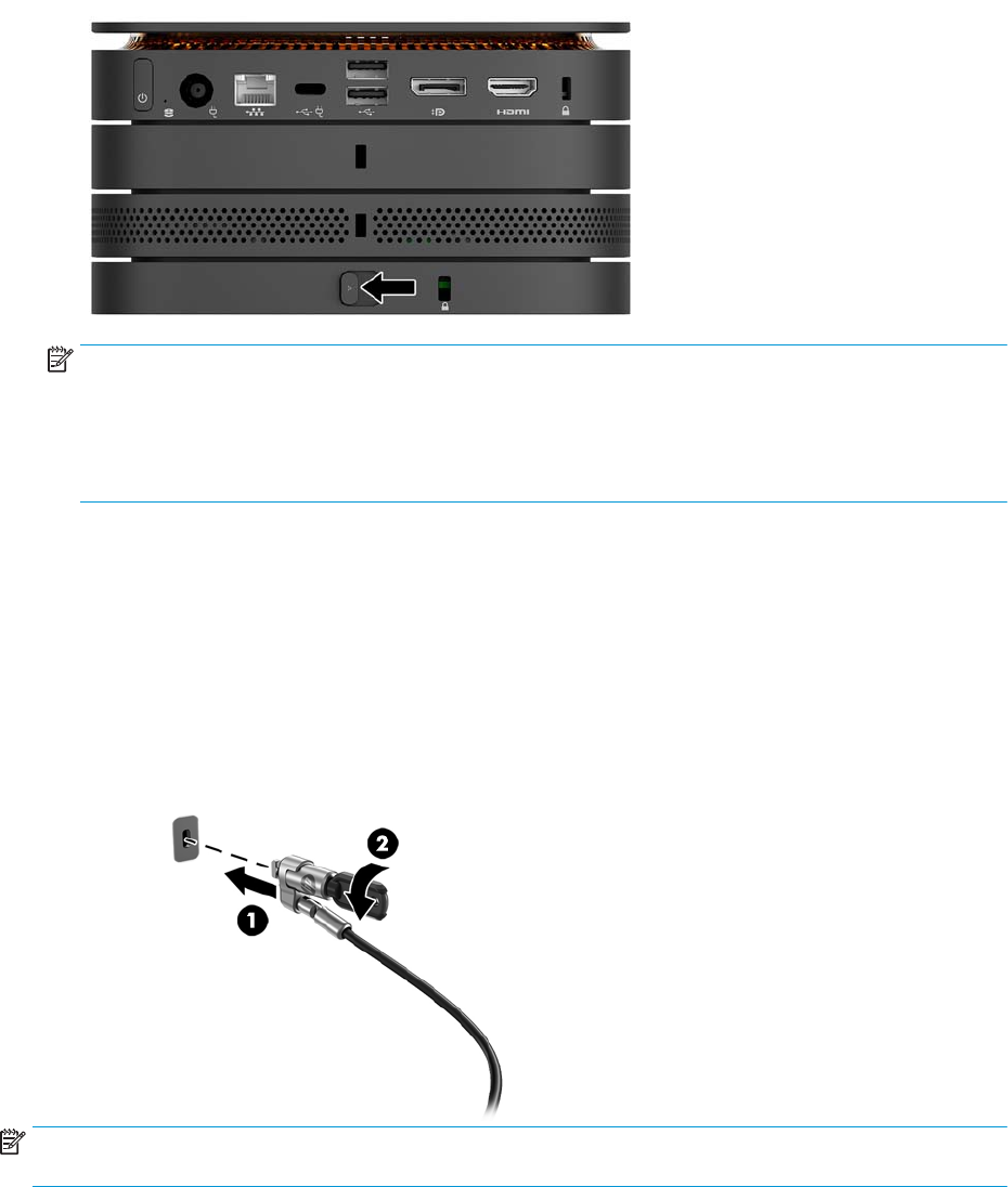
Installing a security cable
The 10 mm ultra-slim cable lock displayed below can be used to secure the computer. When installed in the
bottom module, the cable locks all modules together. If the VESA plate is installed, slide the quick release to
the locked position and install a security cable to lock all modules together.
NOTE: The security cable is designed to act as a deterrent, but it may not prevent the computer from being
mishandled or stolen.
Installing a security cable 13
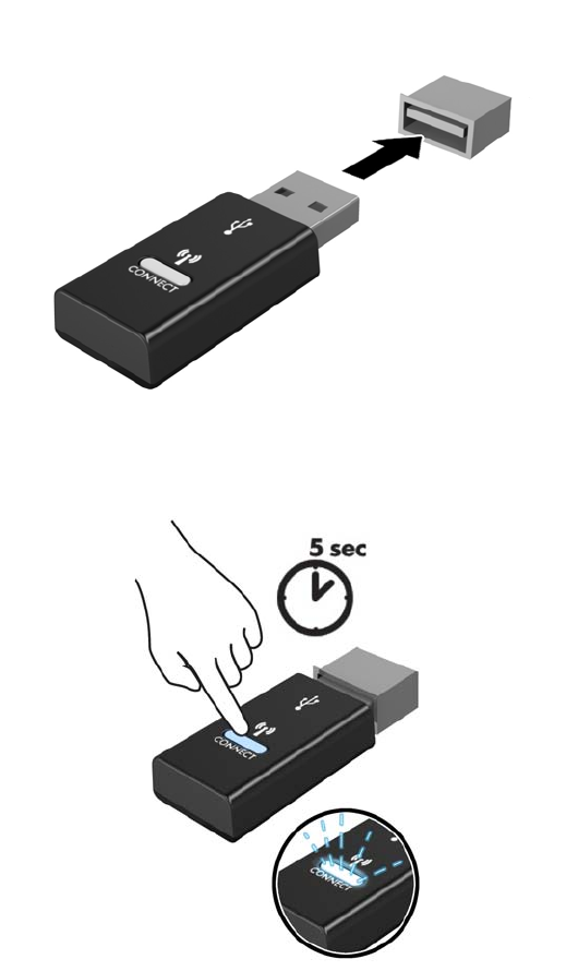
Synchronizing the optional wireless keyboard and mouse
The mouse and keyboard are synchronized at the factory. If they do not work, remove and replace the
batteries. If the mouse and keyboard still do not work, then follow this procedure to manually resynchronize
the pair.
1.
2.
14 Chapter 2 Setup
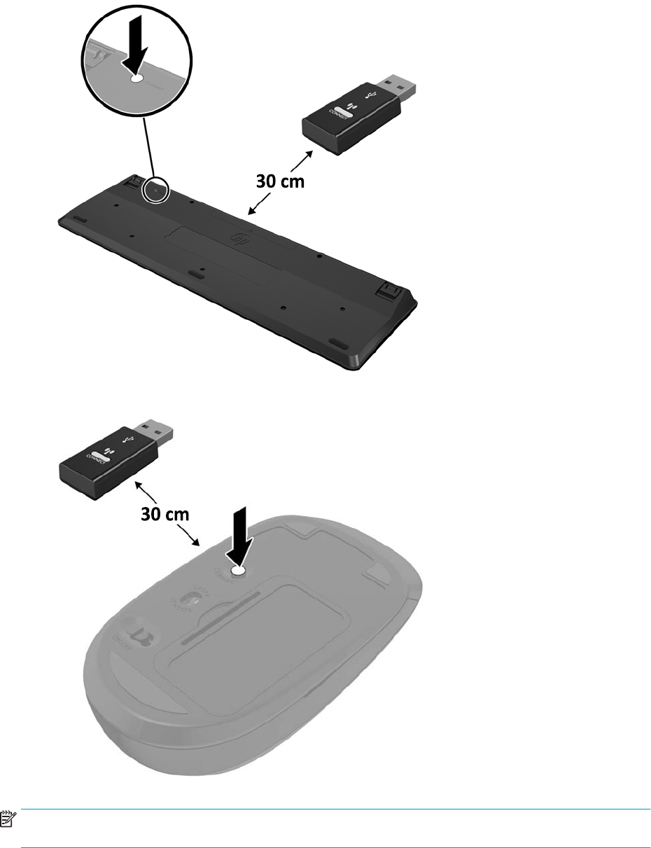
3.
4.
NOTE: If the mouse and keyboard still do not work, then remove and replace the batteries. If the mouse and
keyboard are still not synchronized, then synchronize the keyboard and mouse again.
Synchronizing the optional wireless keyboard and mouse 15

3 Hardware upgrades
Serviceability features
The computer includes features that make it easy to upgrade and service.
Warnings and cautions
Before performing upgrades, be sure to carefully read all of the applicable instructions, cautions, and
warnings in this guide.
WARNING! To reduce the risk of personal injury from electric shock, hot surfaces, or re:
Disconnect the power cord from the AC outlet before removing the enclosure. Energized and moving parts are
inside.
Allow the internal system components to cool before you touch them.
Replace and secure the enclosure before restoring power to the equipment.
Do not connect telecommunications or telephone connectors to the network interface controller (NIC)
receptacles.
Do not disable the power cord grounding plug. The grounding plug is an important safety feature.
Plug the power cord into a grounded (earthed) AC outlet that is easily accessible at all times.
To reduce the risk of serious injury, read the Safety & Comfort Guide. It describes proper workstation setup
and provides guidelines for posture and work habits that increase your comfort and decrease your risk of
injury. It also provides electrical and mechanical safety information. This guide is located on the web at
http://www.hp.com/ergo.
CAUTION: Static electricity can damage the electrical components of the computer or optional equipment.
Before beginning these procedures, ensure that you are discharged of static electricity by briey touching a
grounded metal object. See Electrostatic discharge on page 25 for more information.
When the computer is plugged into an AC power source, voltage is always applied to the system board. You
must disconnect the power cord from the power source before opening the computer to prevent damage to
internal components.
16 Chapter 3 Hardware upgrades
Removing and replacing the access panel
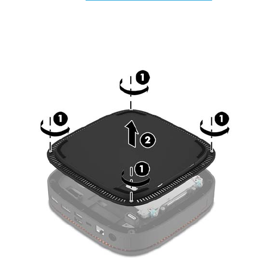
Removing the access panel
The Elite Slice access panel must be removed to access the hard drive and system memory modules.
1. Remove the Elite Slice from any additional modules.
For instructions, see Removing modules on page 11.
2. Place the computer upside down on a at surface covered with a soft cloth to protect the computer from
scratches or other damage.
3. Loosen the four captive screws (1) securing the access panel, and lift the panel o the computer (2).
Replacing the access panel
1. Place the computer upside down on a at surface covered with a soft cloth.
2. Align the access panel (1) with the computer so that the module connection port is clearly visible
through the opening in the access panel.
Removing and replacing the access panel 17
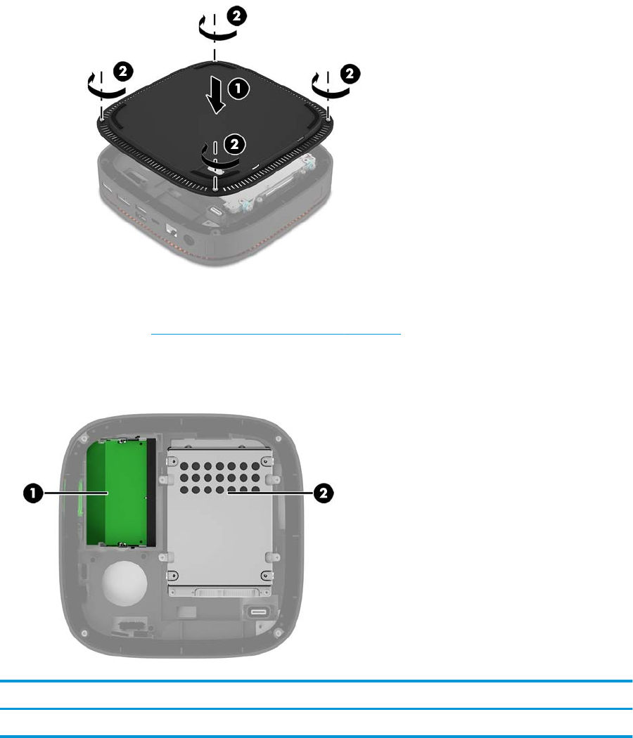
3. Tighten the four captive screws (2) to secure the access panel to the computer.
4. Reconnect any additional modules.
For instructions, see Connecting or removing modules on page 8.
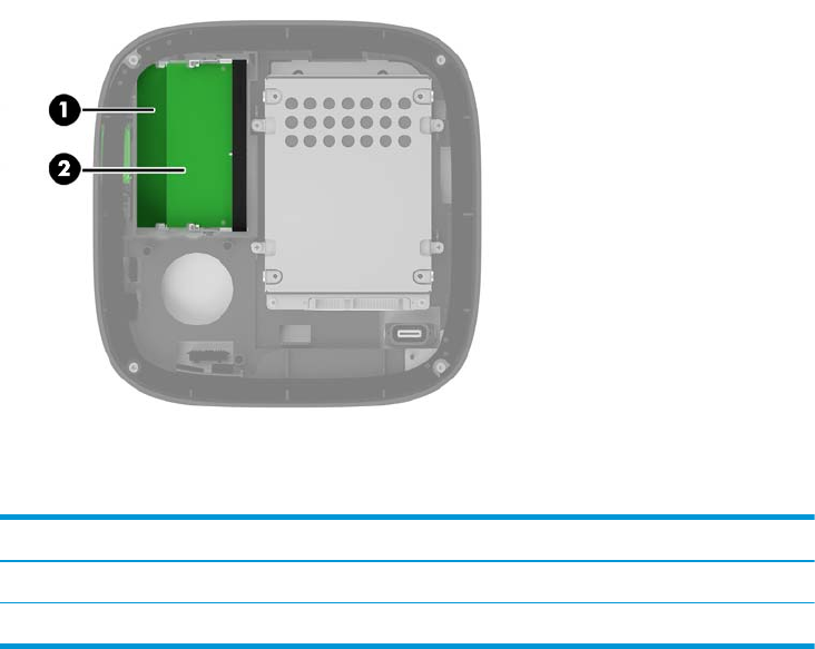
Locating internal components
Item Component Item Component
1 System memory modules 2 Hard drive
18 Chapter 3 Hardware upgrades

Upgrading system memory
The memory module slots on the system board can be populated with up to two industry-standard memory
modules. At least one small outline, dual inline memory module (SODIMM) is preinstalled. To achieve the
maximum memory support, you can populate the system board with up to 32 GB (16 GB x 2) of memory.
Memory module specications
For proper system operation, the SODIMMs must adhere to the following specications:
●industry-standard 288-pins
●unbuered non-ECC PC4-17000 DDR4-2133 MHz-compliant
●1.2 volt DDR4-SDRAM SODIMMs
●Support CAS latency 15 DDR4 2133 MHz (15-15-15 timing)
●Contain the mandatory Joint Electronic Device Engineering Council (JEDEC) specication
The computer supports the following:
●512-Mbit, 1-Gbit, and 2-Gbit non-ECC memory technologies
●Single-sided and double-sided SODIMMS
●SODIMMs constructed with x8 and x16 devices
NOTE: To avoid compatibility issues, HP recommends that you use only HP memory modules in this
computer. The system will not operate properly if you install unsupported DIMM memory. DIMMs constructed
with x4 SDRAM are not supported.
Upgrading system memory 19
Populating memory module slots
There are two memory module slots, one slot per channel. The slots are labeled DIMM1 and DIMM3. The
DIMM1 slot operates in memory channel B. The DIMM3 slot operates in memory channel A.
Item Description System Board Label Slot Color
1 Memory 1 slot, Channel B DIMM1 Black
2 Memory 3 slot, Channel A DIMM3 Black
The system automatically operates in single-channel mode, dual-channel mode, or ex mode, depending on
how the memory modules are installed.
●The system operates in single-channel mode if only one memory module slot is populated.
●The system operates in higher-performing, dual-channel mode if the capacity of the memory modules
in Channel A and Channel B are equal.
●The system operates in ex mode if the capacity of the memory modules in Channel A and Channel B are
not equal. In ex mode, the channel populated with the least amount of memory determines the total
amount of memory that is assigned to dual-channel operation, and the remainder is assigned to single-
channel operation. In ex mode, install the memory module with the larger capacity in the DIMM3 slot
(Channel A).
●In any mode, the maximum operational speed is determined by the slowest memory module in the
system.
20 Chapter 3 Hardware upgrades
Installing system memory modules
CAUTION: You must disconnect the power cord and wait approximately 30 seconds for the power to drain
before adding or removing memory modules. Regardless of the power-on state, voltage is always supplied to
the memory modules as long as the computer is plugged into an active AC outlet. Adding or removing
memory modules while voltage is present may cause irreparable damage to the memory modules or system
board.
The memory module slots have gold-plated metal contacts. When upgrading the memory, it is important to
use memory modules with gold-plated metal contacts to prevent corrosion and/or oxidation resulting from
having incompatible metals in contact with each other.
Static electricity can damage the electronic components of the computer or optional cards. Before beginning
these procedures, ensure that you are discharged of static electricity by briey touching a grounded metal
object. For more information, see Electrostatic discharge on page 25.
When handling a memory module, be careful not to touch any of the contacts. Doing so may damage the
module.
1. Remove the access panel.
For instructions, see Removing the access panel on page 17.
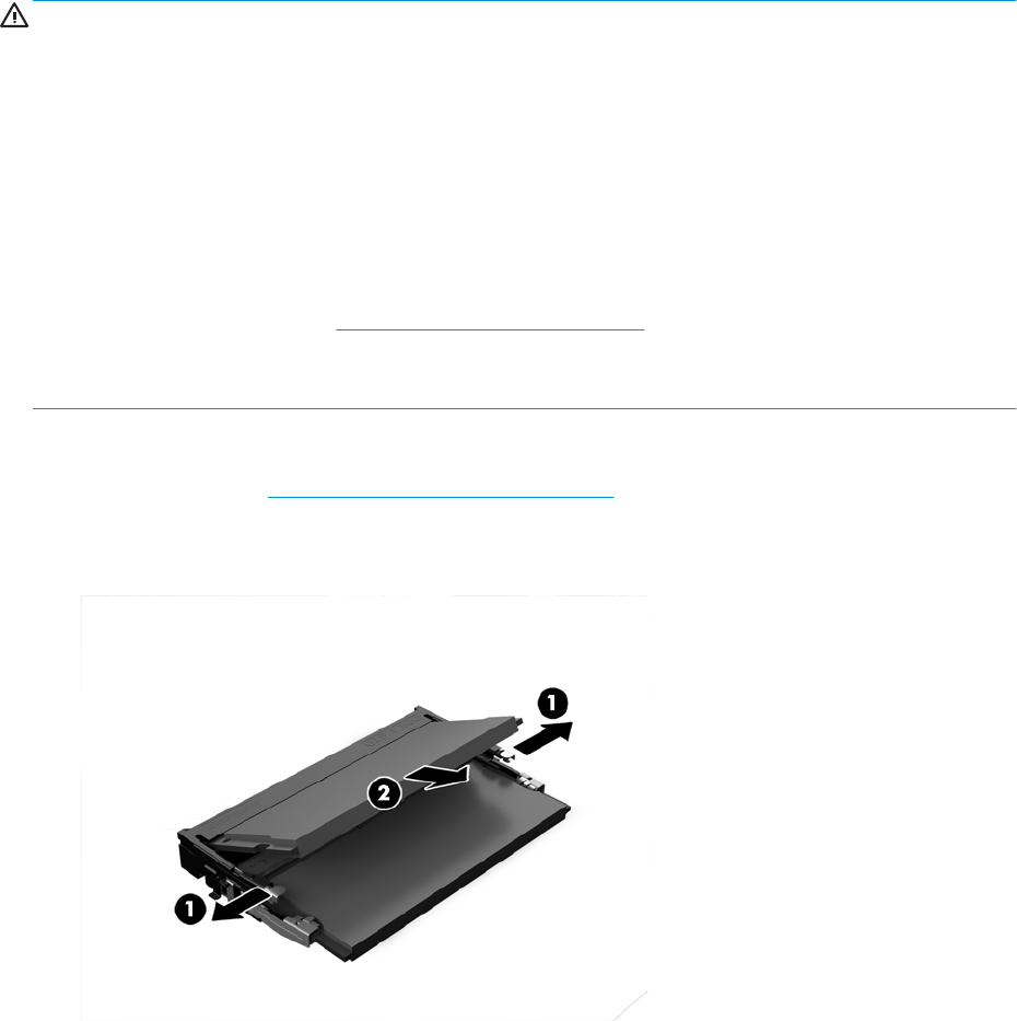
2. To remove a memory module, press outward on the two latches on each side of the memory module (1),
and then pull the memory module out of the slot (2).
Upgrading system memory 21
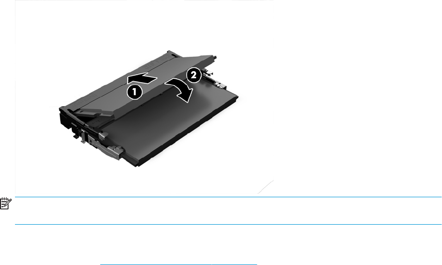
3. Insert the new memory module into the slot at approximately a 30° angle (1), and then press the
memory module (2) into the slot so that the latches lock it in place.
NOTE: A memory module can be installed in only one way. Match the notch on the module with the tab
on the memory module slot.
4. Replace the access panel.
For instructions, see Replacing the access panel on page 17.
The computer automatically recognizes the additional memory when you turn on the computer.
22 Chapter 3 Hardware upgrades
Removing and replacing a hard drive
NOTE: Back up the hard drive before you remove it so that you can transfer the data to the new hard drive.
1. Remove the access panel.
For instructions, see Removing the access panel on page 17.
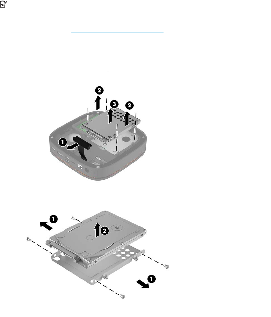
2. Pull the tab (1) to disconnect the hard drive power-and-data cable from the hard drive.
3. Remove the 4 screws (2) attaching the hard drive cage to the board and lift the cage (3) out of the
chassis.
4. Remove the screws (1) securing the hard drive in the cage and lift the hard drive (2) out of the cage.
5. Position the new hard drive over the drive cage with the hard drive connectors at the end with the
thermal patch and the circuit board side facing the closed side of the drive cage.
6. Set the new hard drive (1) into the cage. Be sure the label side of the hard drive is visible.
Removing and replacing a hard drive 23
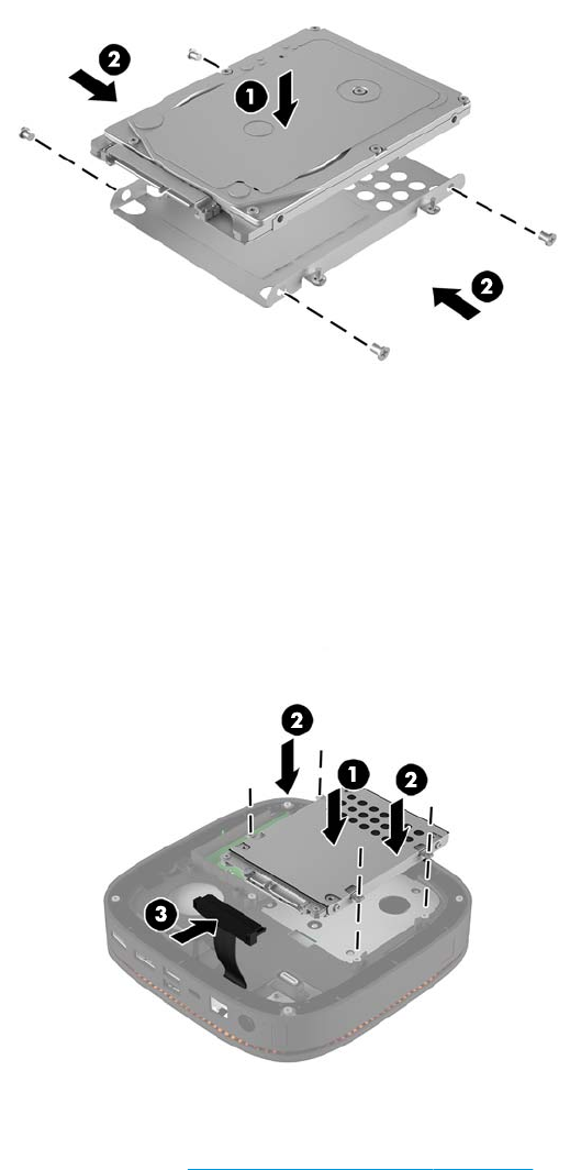
7. Fasten the four screws (2) to secure the hard drive in the cage.
8. Replace the hard drive cage (1) in the chassis. Be sure that the hard drive connectors are facing the back
of the chassis.
9. Align the drive cage tabs with the screw posts in the chassis and fasten the four screws (2) to secure the
hard drive.
10. Reconnect the power-and-data cable (3) to the hard drive.
11. Replace the access panel.
For instructions, see Replacing the access panel on page 17.
24 Chapter 3 Hardware upgrades

A Electrostatic discharge
A discharge of static electricity from a nger or other conductor may damage system boards or other static-
sensitive devices. This type of damage may reduce the life expectancy of the device.
Preventing electrostatic damage
To prevent electrostatic damage, observe the following precautions:
●Avoid hand contact by transporting and storing products in static-safe containers.
●Keep electrostatic-sensitive parts in their containers until they arrive at static-free workstations.
●Place parts on a grounded surface before removing them from their containers.
●Avoid touching pins, leads, or circuitry.
●Always be properly grounded when touching a static-sensitive component or assembly.
Grounding methods
Use one or more of the following methods when handling or installing electrostatic-sensitive parts:
●Use a wrist strap connected by a ground cord to a grounded workstation or computer chassis. Wrist
straps are exible straps with a minimum of 1 megohm +/- 10 percent resistance in the ground cords. To
provide proper ground, wear the strap snug against the skin.
●Use heelstraps, toestraps, or bootstraps at standing workstations. Wear the straps on both feet when
standing on conductive oors or dissipating oor mats.
●Use conductive eld service tools.
●Use a portable eld service kit with a folding static-dissipating work mat.
If you do not have any of the suggested equipment for proper grounding, contact an HP authorized dealer,
reseller, or service provider.
NOTE: For more information on static electricity, contact an HP authorized dealer, reseller, or service
provider.
Preventing electrostatic damage 25

B Computer operating guidelines, routine
care and shipping preparation
Computer operating guidelines and routine care
Follow these guidelines to properly set up and care for the computer and monitor:
●Keep the computer away from excessive moisture, direct sunlight, and extremes of heat and cold.
●Operate the computer on a sturdy, level surface. Leave a 10.2 cm (4 in) clearance on all vented sides of
the computer and above the monitor to permit the required airow.
●Never restrict the airow into the computer by blocking any vents or air intakes. Do not place the
keyboard, with the keyboard feet down, directly against the front of the desktop unit as this also
restricts airow.
●Never operate the computer with the access panel or any of the expansion card slot covers removed.
●Do not stack computers on top of each other or place computers so near each other that they are subject
to each other’s recirculated or preheated air.
●If the computer is to be operated within a separate enclosure, intake and exhaust ventilation must be
provided on the enclosure, and the same operating guidelines listed above will still apply.
●Keep liquids away from the computer and keyboard.
●Never cover the ventilation slots on the monitor with any type of material.
●Install or enable power management functions of the operating system or other software, including
sleep states.
●Turn o the computer before you do either of the following:
—Wipe the exterior of the computer with a soft, damp cloth as needed. Using cleaning products may
discolor or damage the nish.
—Occasionally clean the air vents on all vented sides of the computer. Lint, dust, and other foreign
matter can block the vents and limit the airow.
26 Appendix B Computer operating guidelines, routine care and shipping preparation

Shipping preparation
Follow these suggestions when preparing to ship the computer:
1. Back up the hard drive les to an external storage device. Be sure that the backup media is not exposed
to electrical or magnetic impulses while stored or in transit.
NOTE: The hard drive locks automatically when the system power is turned o.
2. Remove and store all removable media.
3. Turn o the computer and external devices.
4. Disconnect the power cord from the AC outlet and then from the computer.
5. Disconnect the system components and external devices from their power sources and then from the
computer.
NOTE: Ensure that all boards are seated properly and secured in the board slots before shipping the
computer.
6. Pack the system components and external devices in their original packing boxes or similar packaging,
with suicient packing material to protect them.
Shipping preparation 27

C Accessibility
HP designs, produces, and markets products and services that can be used by everyone, including people with
disabilities, either on a stand-alone basis or with appropriate assistive devices.
Supported assistive technologies
HP products support a wide variety of operating system assistive technologies and can be congured to work
with additional assistive technologies. Use the Search feature on your device to locate more information
about assistive features.
NOTE: For additional information about a particular assistive technology product, contact customer support
for that product.
Contacting support
We are constantly rening the accessibility of our products and services and welcome feedback from users. If
you have an issue with a product or would like to tell us about accessibility features that have helped you,
please contact us at (888) 259-5707, Monday through Friday, 6 a.m. to 9 p.m. Mountain Time. If you are deaf
or hard-of-hearing and use TRS/VRS/WebCapTel, contact us if you require technical support or have
accessibility questions by calling (877) 656-7058, Monday through Friday, 6 a.m. to 9 p.m. Mountain Time.
28 Appendix C Accessibility

Index
A
access panel
removing 17
replacing 17
accessibility 28
audio module features 6
B
base module features 1
C
cautions 16
collaboration cover features 3
computer operating guidelines 26
connecting modules 8
connecting power 11
E
electrostatic discharge, preventing
damage 25
F
features
audio module 6
base module 1
collaboration cover 3
optical drive module 5
VESA plate 6
wireless charging cover 4
H
hard drive
installating 23
removing 23
HP Audio Module 6
HP Collaboration Cover 3
HP Elite Slice features 1
HP ODD Module 5
HP Tri-Band Wireless Charging
Cover 4
HP VESA Plate 6
I
installation guidelines 16
installing
hard drive 23
security cable 13
system memory 19, 21
internal components 18
K
keyboard, synchronizing wireless
14
M
memory, system
installing 19, 21
replacing 21
slot population 20
slots 19
specications 19
module order 8
module sequence 8
modules
connecting 8
removing 11
mounting HP Elite Slice 12
mouse, synchronizing wireless 14
O
optical drive module features 5
P
product ID location 7
R
removing
access panel 17
hard drive 23
modules 11
replacing
access panel 17
system memory 21
S
security cable, installing 13
serial number location 7
setup 8
shipping preparation 27
specications, system memory 19
synchronizing wireless keyboard and
mouse 14
V
ventilation guidelines 26
VESA plate features 6
W
warnings 16
wireless charging cover features 4
Index 29