Inventek Systems 341 5.0 GHz WiFi Transmitter User Manual
Inventek Systems 5.0 GHz WiFi Transmitter
UserManual.wiki
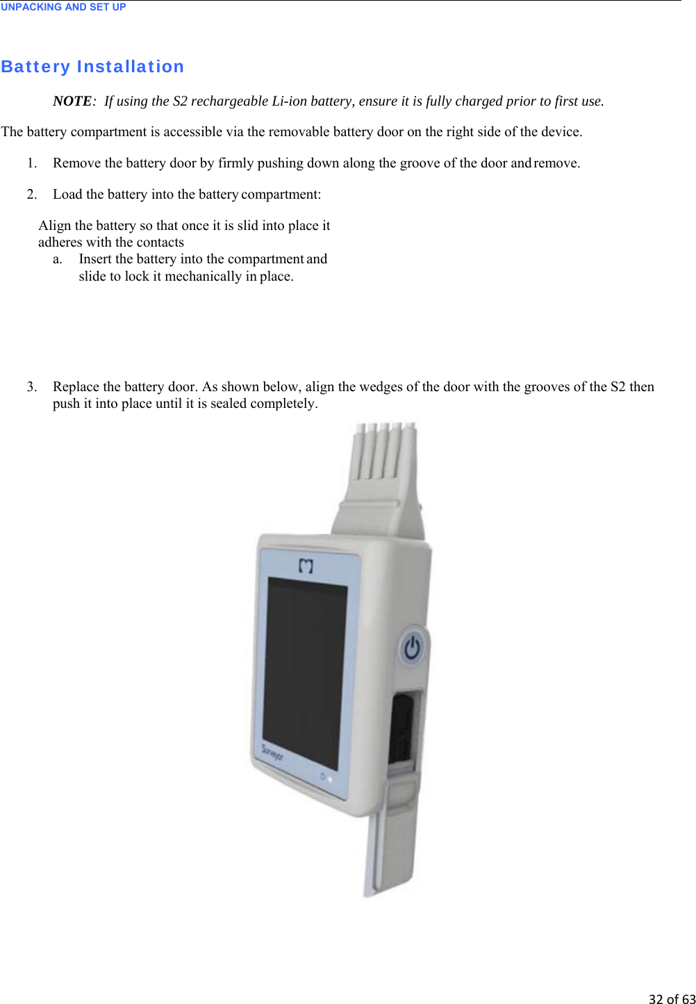
>
Inventek Systems
>
341 User Manual
>
User Manual
Contents
1.
Users Manual
2.
User Manual
User Manual
Navigation menu
Upload a User Manual
Namespaces
Wiki Guide
HTML
PDF
Info
Views
User Manual
Discussion / Help
Navigation
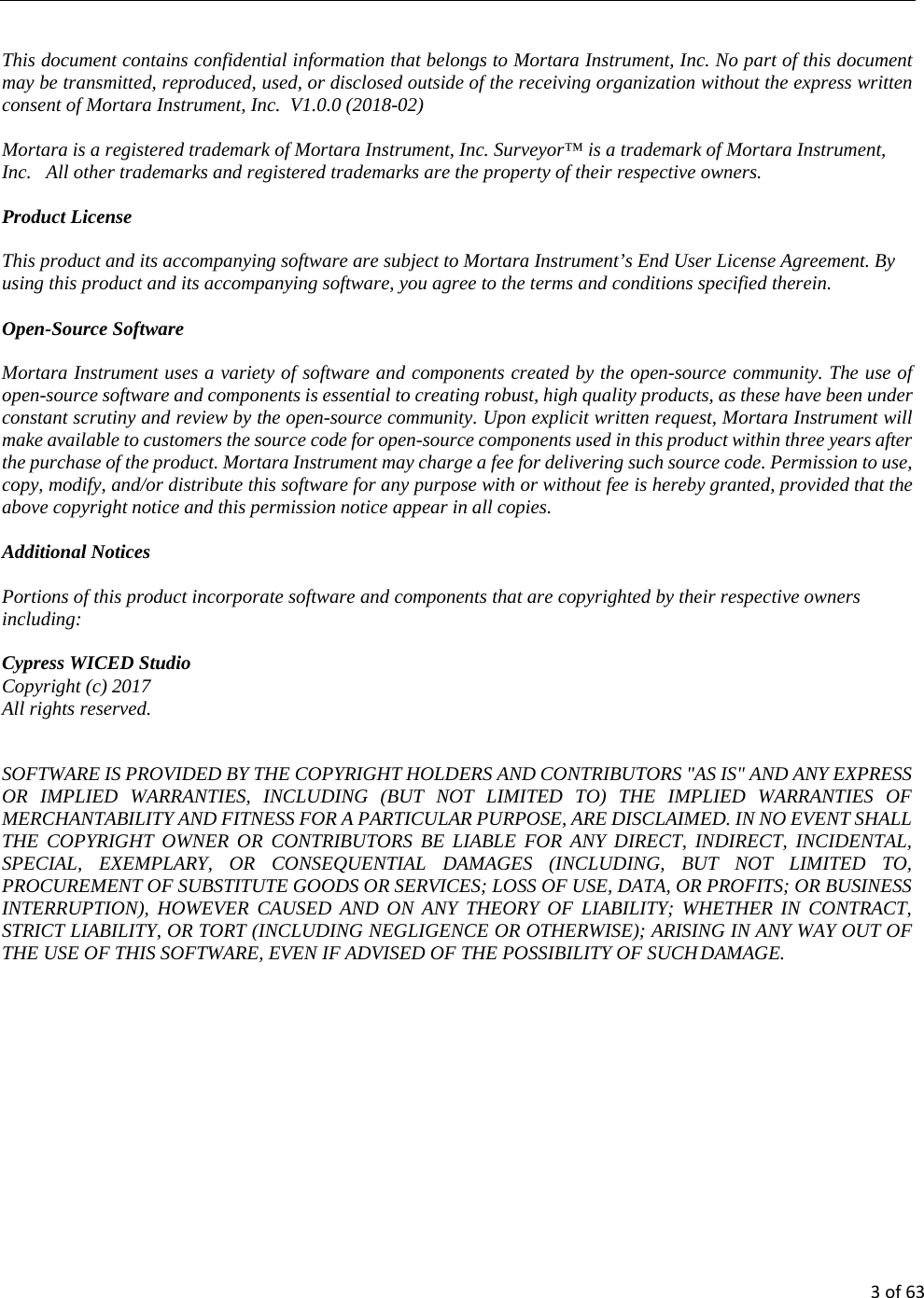
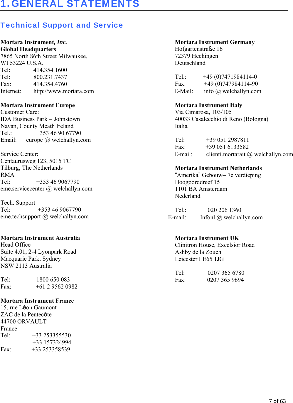
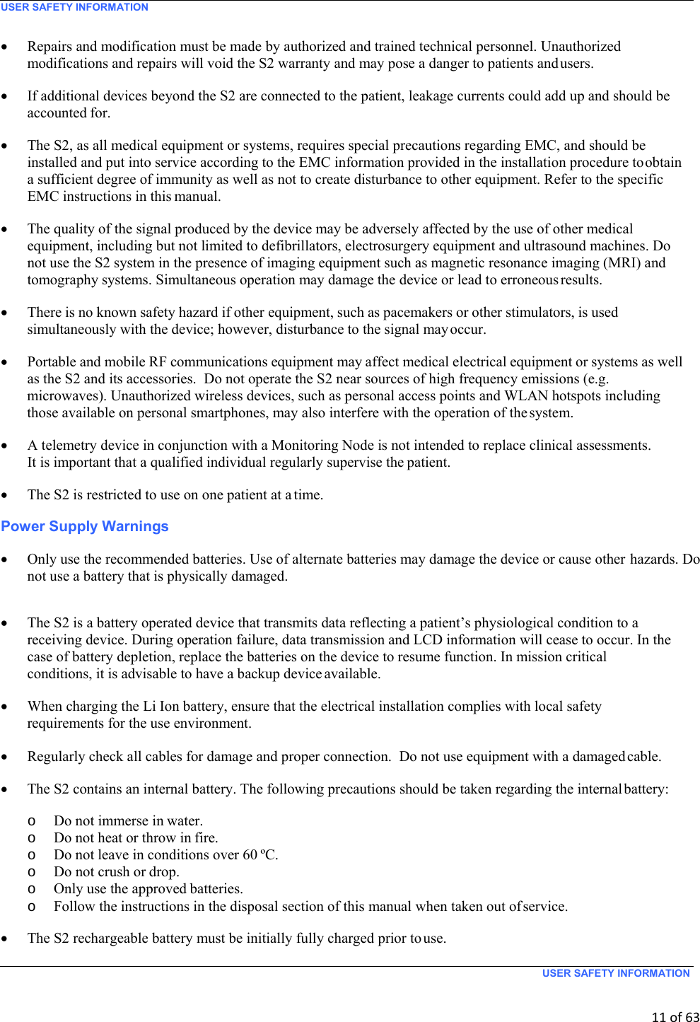
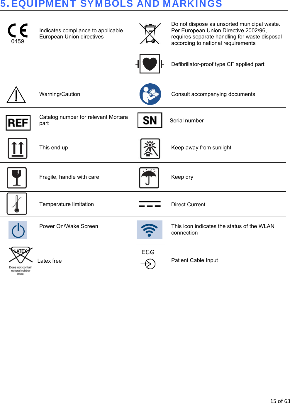
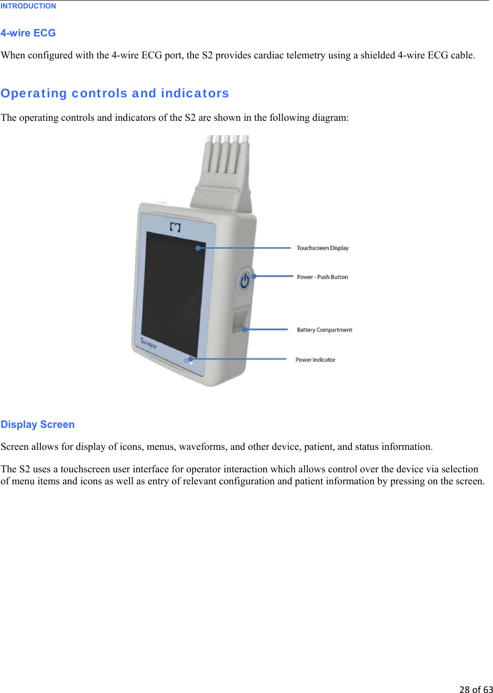
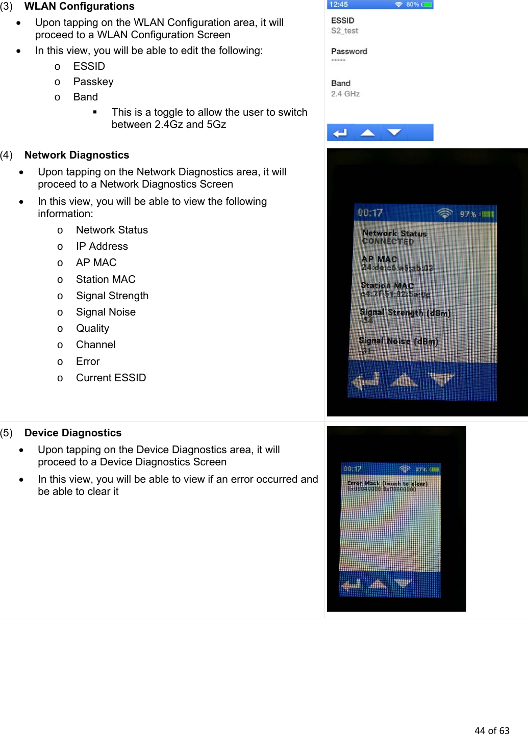
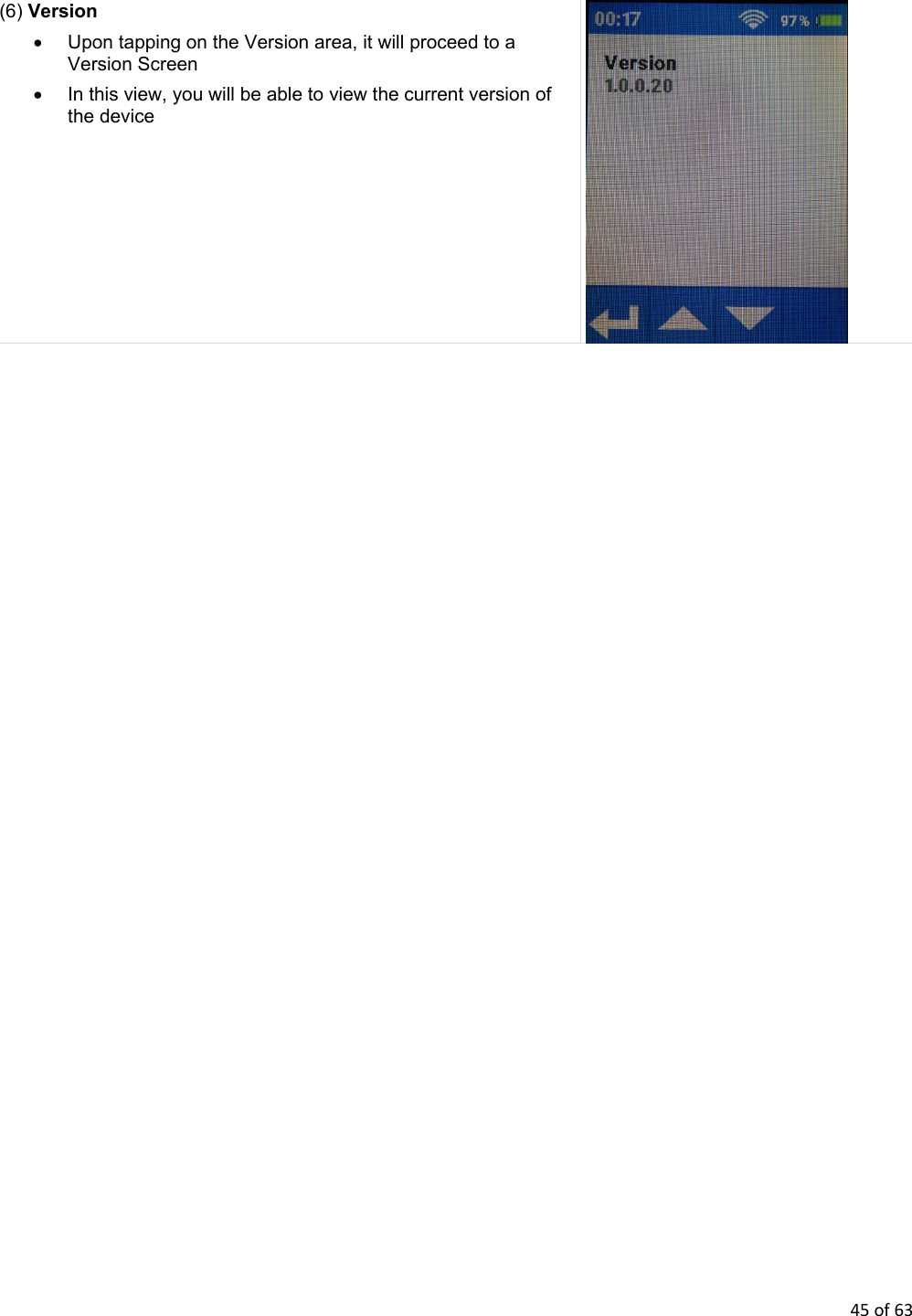
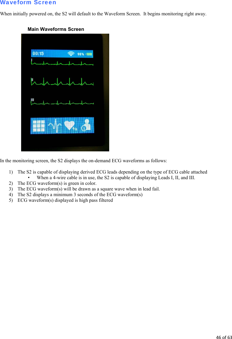
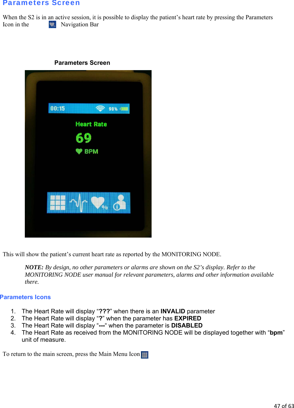
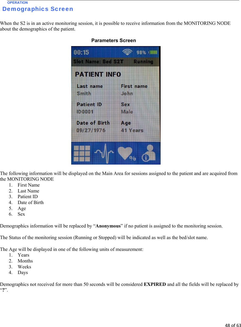
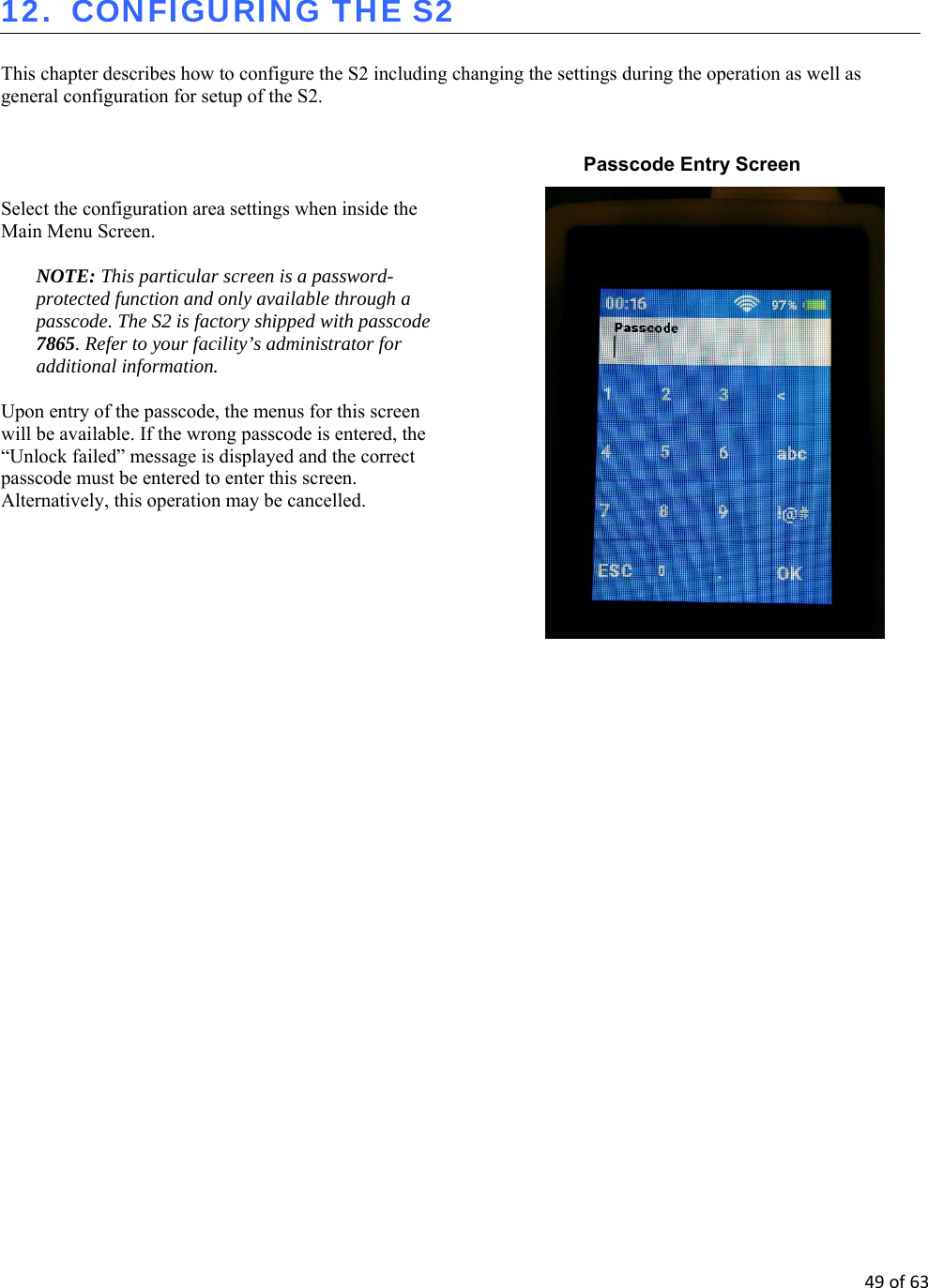
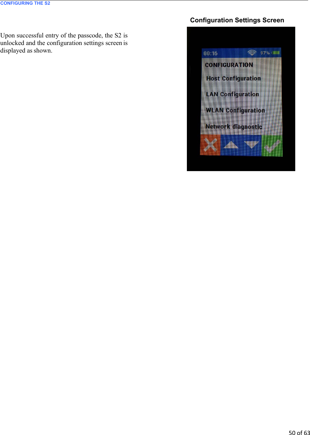
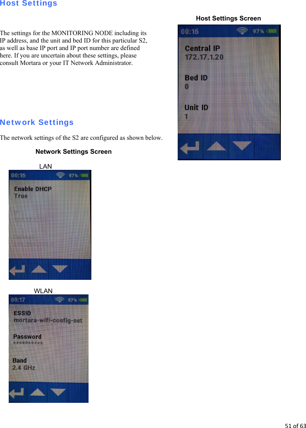
![17of63 GENERAL CARE S2 Battery Compartment – Inspect the S2’s battery spring contacts and the battery door latching mechanism for signs of excessive wear. If the battery compartment has been damaged, contact Mortara Technical Support for assistance. Battery Charger bay – Inspect the Li-Ion Battery Charger’s contacts and mechanisms for signs of excessive wear. Rechargeable Li-Ion Battery – Follow the instructions and note the cautions labeled on the rechargeable battery. Contact Mortara for replacement. Device Labeling – Inspect the device labeling for signs of wear and legibility. If the labeling is no longer clear and legible, contact Mortara Technical Support for assistance. Cleaning and Disinfecting This section describes the procedures for cleaning and disinfecting the S2, its sensors and accessories. WARNING: Follow these instructions to clean and disinfect the S2 and its accessories. Improper cleaning may cause damage that is not immediately apparent, leading to possible safety hazards, device malfunction, and/or spread of infectious agents between persons. Disinfecting agents The S2 is compatible with the following disinfectants: Clorox Healthcare® Bleach Germicidal Wipes (use according to instructions on product label), or a soft, lint-free cloth dampened with a solution of sodium hypochlorite (10% household bleach and water solution) minimum 1:500 dilution (minimum 100 ppm free chlorine) and maximum 1:10 dilution as recommended by the APIC Guidelines for Selection and Use of Disinfectants. Cleaning and disinfecting the S2 monitor WARNING: Do not immerse the S2 in water or any other fluids. The S2 is not designed to be immersed in liquid and doing so may result in liquid entering the device leading to possible safety hazards and/or device malfunction. CAUTION: Do not steam autoclave, gas sterilize, or irradiate the S2 as these may result in damage to the device. WARNING: Ensure the battery door is securely in place when cleaning the S2 to avoid risk of liquid entering into the device which may lead to a possible hazard and/or device malfunction. To clean the S2: 1. Switch off the S2. If on, press and hold the Push-Button button on the right side of the device to turn on the display screen. Press the configuration key on the touch screen, then select [Shutdown Device]. 2. Disconnect patient cables from the S2.](https://usermanual.wiki/Inventek-Systems/341.User-Manual/User-Guide-3861400-Page-17.png)
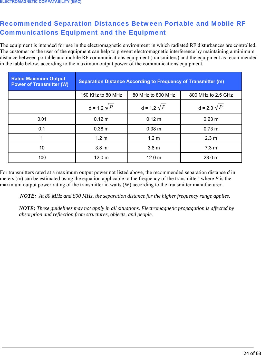
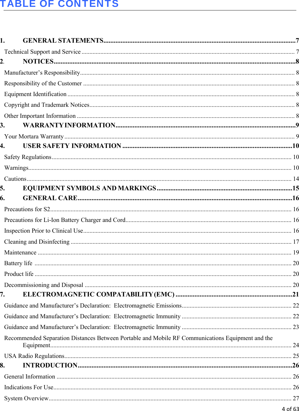
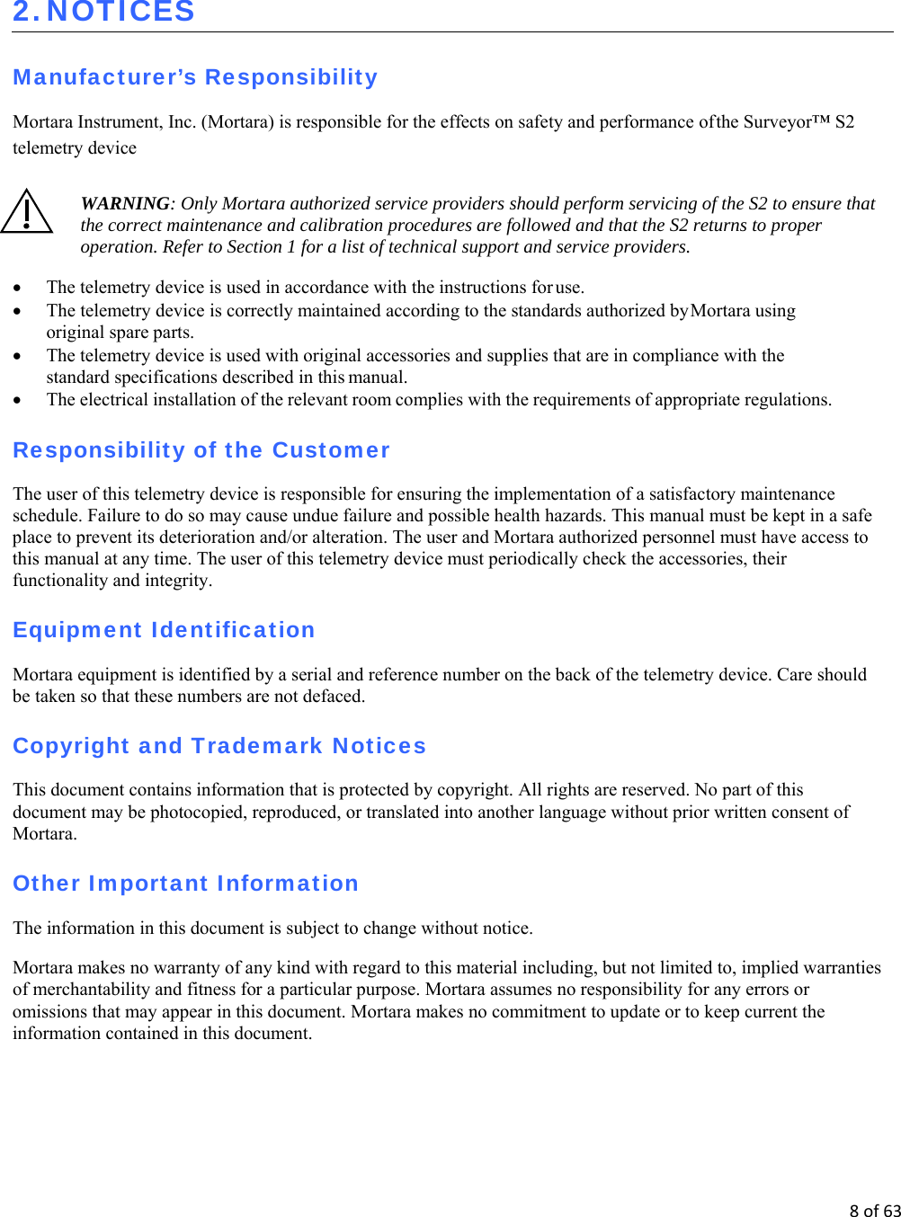
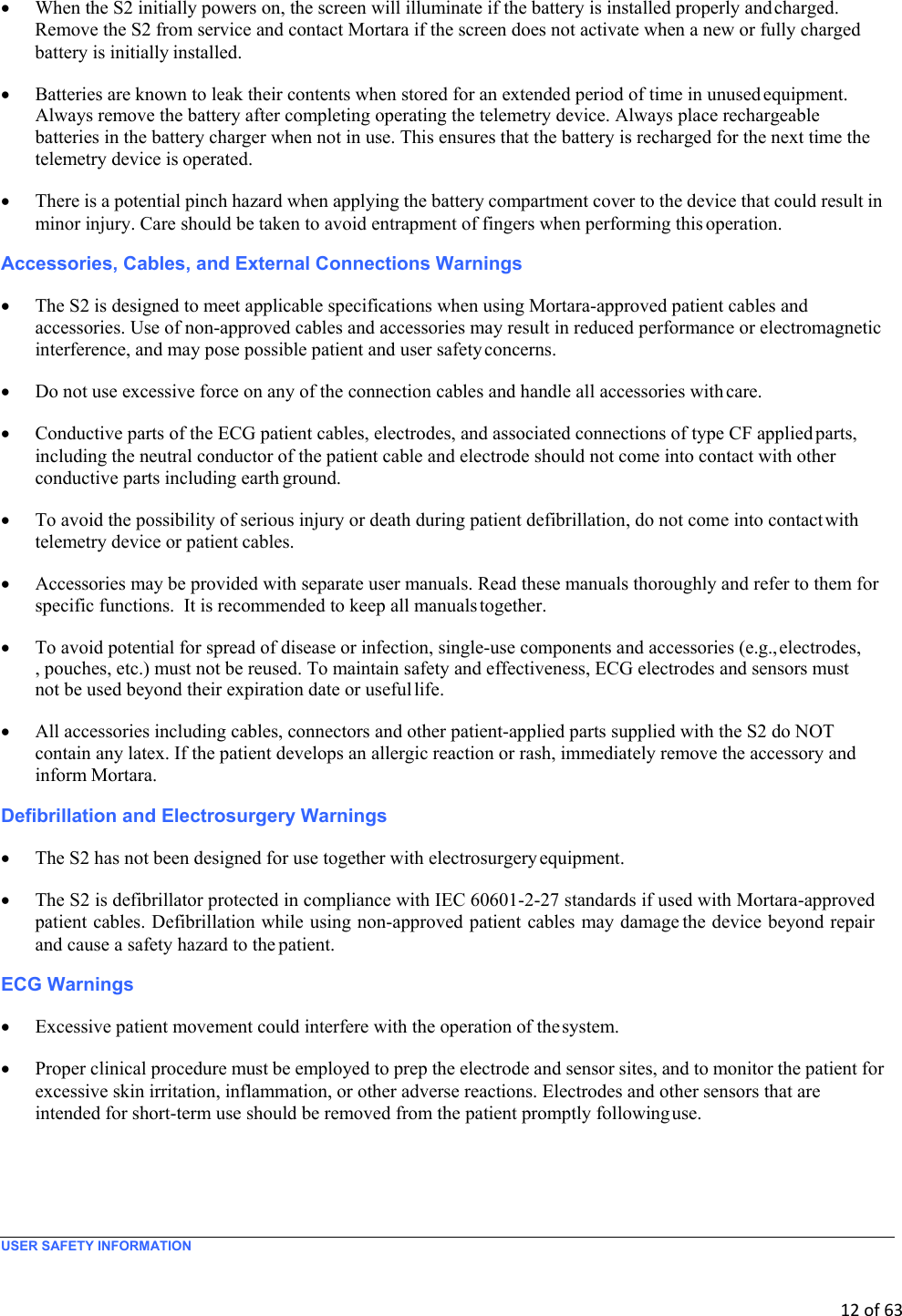
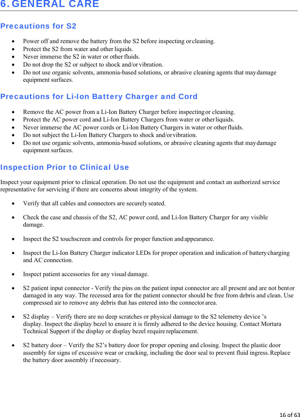
![23of63 ELECTROMAGNETIC COMPATABILITY (EMC) Guidance and Manufacturer’s Declaration: Electromagnetic Immunity The equipment is intended for use in the electromagnetic environment specified in the table below. The customer or the user of the equipment should ensure that it is used in such an environment. Immunity Test IEC 60601 Test Level Compliance Level Electromagnetic Environment: Guidance Conducted RF EN 61000-4-6 3 Vrms 150 kHz to 80 MHz 3 Vrms 150 kHz to 80 MHz Portable and mobile RF communications equipment should be used no closer to any part of the equipment, including cables, than the recommended separation distance calculated from the equation applicable to the frequency of the transmitter. Recommended separation distance d = 1.2 d = 1.2 80 MHz to 800 MHz d = 800 MHz to 2.5 GHz Where P is the maximum output power rating of the transmitter in watts (W) according to the transmitter manufacturer and d is the recommended separation distance in meters (m). Field strengths from fixed RF transmitters, as determined by an electromagnetic site surveya, should be less than the compliance level in each frequency rangeb. Interference may occur in the vicinity of equipment marked with the following symbol: Radiated RF IEC 61000-4-3 10 V/m 80 MHz to 2.7 GHz 10 V/m 80 MHz to 2.7 GHz a. Field strengths from fixed transmitters, such as base stations for radio (cellular/cordless) telephones and land mobile radios, amateur radios, AM and FM radio broadcast, and TV broadcast cannot be predicted theoretically with accuracy. To assess the electromagnetic environment due to fixed RF transmitters, an electromagnetic site survey should be considered. If the measured field strength in the location in which the equipment is used exceeds the applicable RF compliance level above, the equipment should be observed to verify normal operation. If abnormal performance is observed, additional measures may be necessary, such as reorienting or relocating the equipment. b. Over the frequency range 150 kHz to 80 MHz, field strengths should be less than [3] V/m.](https://usermanual.wiki/Inventek-Systems/341.User-Manual/User-Guide-3861400-Page-23.png)