Inventek Systems 341 5.0 GHz WiFi Transmitter User Manual
Inventek Systems 5.0 GHz WiFi Transmitter
Contents
- 1. Users Manual
- 2. User Manual
User Manual
1of63
REF 9515-210-50-ENG Rev A1
Surveyor
S2 Telemetry
Device
USER MANUAL
Manufactured by Mortara Instrument, Inc., Milwaukee, Wisconsin U.S.A.
CAUTION: United States federal law restricts this device to sale by or on the order of a physician.

2of63
Copyright © 2018
by Mortara Instrument, Inc.
7865 N. 86th Street
Milwaukee, Wisconsin 53224
E-mail: techsupport@mortara.com
Mortara, the Mortara logo, Surveyor, and VERITAS are trademarks belonging to Mortara Instrument, Inc.
Clorox Healthcare® is a registered trademark of The Clorox Company.

3of63
This document contains confidential information that belongs to Mortara Instrument, Inc. No part of this document
may be transmitted, reproduced, used, or disclosed outside of the receiving organization without the express written
consent of Mortara Instrument, Inc. V1.0.0 (2018-02)
Mortara is a registered trademark of Mortara Instrument, Inc. Surveyor™ is a trademark of Mortara Instrument,
Inc. All other trademarks and registered trademarks are the property of their respective owners.
Product License
This product and its accompanying software are subject to Mortara Instrument’s End User License Agreement. By
using this product and its accompanying software, you agree to the terms and conditions specified therein.
Open-Source Software
Mortara Instrument uses a variety of software and components created by the open-source community. The use of
open-source software and components is essential to creating robust, high quality products, as these have been under
constant scrutiny and review by the open-source community. Upon explicit written request, Mortara Instrument will
make available to customers the source code for open-source components used in this product within three years after
the purchase of the product. Mortara Instrument may charge a fee for delivering such source code. Permission to use,
copy, modify, and/or distribute this software for any purpose with or without fee is hereby granted, provided that the
above copyright notice and this permission notice appear in all copies.
Additional Notices
Portions of this product incorporate software and components that are copyrighted by their respective owners
including:
Cypress WICED Studio
Copyright (c) 2017
All rights reserved.
SOFTWARE IS PROVIDED BY THE COPYRIGHT HOLDERS AND CONTRIBUTORS "AS IS" AND ANY EXPRESS
OR IMPLIED WARRANTIES, INCLUDING (BUT NOT LIMITED TO) THE IMPLIED WARRANTIES OF
MERCHANTABILITY AND FITNESS FOR A PARTICULAR PURPOSE, ARE DISCLAIMED. IN NO EVENT SHALL
THE COPYRIGHT OWNER OR CONTRIBUTORS BE LIABLE FOR ANY DIRECT, INDIRECT, INCIDENTAL,
SPECIAL, EXEMPLARY, OR CONSEQUENTIAL DAMAGES (INCLUDING, BUT NOT LIMITED TO,
PROCUREMENT OF SUBSTITUTE GOODS OR SERVICES; LOSS OF USE, DATA, OR PROFITS; OR BUSINESS
INTERRUPTION), HOWEVER CAUSED AND ON ANY THEORY OF LIABILITY; WHETHER IN CONTRACT,
STRICT LIABILITY, OR TORT (INCLUDING NEGLIGENCE OR OTHERWISE); ARISING IN ANY WAY OUT OF
THE USE OF THIS SOFTWARE, EVEN IF ADVISED OF THE POSSIBILITY OF SUCH DAMAGE.

4of63
TABLE OF CONTENTS
1.
GENERAL STATEMENTS ................................................................................................................7
Technical Support and Service ........................................................................................................................................ 7
2
.
NOTICES .............................................................................................................................................8
Manufacturer’s Responsibility ......................................................................................................................................... 8
Responsibility of the Customer ....................................................................................................................................... 8
Equipment Identification ................................................................................................................................................. 8
Copyright and Trademark Notices ................................................................................................................................... 8
Other Important Information ........................................................................................................................................... 8
3.
WARRANTY INFORMATION .........................................................................................................9
Your Mortara Warranty ................................................................................................................................................... 9
4.
USER SAFETY INFORMATION ................................................................................................... 10
Safety Regulations ......................................................................................................................................................... 10
Warnings........................................................................................................................................................................ 10
Cautions ......................................................................................................................................................................... 14
5.
EQUIPMENT SYMBOLS AND MARKINGS ............................................................................... 15
6.
GENERAL CARE ............................................................................................................................. 16
Precautions for S2 .......................................................................................................................................................... 16
Precautions for Li-Ion Battery Charger and Cord .......................................................................................................... 16
Inspection Prior to Clinical Use ..................................................................................................................................... 16
Cleaning and Disinfecting ............................................................................................................................................. 17
Maintenance .................................................................................................................................................................. 19
Battery life .................................................................................................................................................................... 20
Product life .................................................................................................................................................................... 20
Decommissioning and Disposal .................................................................................................................................... 20
7.
ELECTROMAGNETIC COMPATABILITY (EMC) .................................................................... 21
Guidance and Manufacturer’s Declaration: Electromagnetic Emissions ...................................................................... 22
Guidance and Manufacturer’s Declaration: Electromagnetic Immunity ...................................................................... 22
Guidance and Manufacturer’s Declaration: Electromagnetic Immunity ...................................................................... 23
Recommended Separation Distances Between Portable and Mobile RF Communications Equipment and the
Equipment .......................................................................................................................................................... 24
USA Radio Regulations ................................................................................................................................................. 25
8.
INTRODUCTION ............................................................................................................................. 26
General Information ...................................................................................................................................................... 26
Indications For Use ........................................................................................................................................................ 26
System Overview ........................................................................................................................................................... 27
5of63
Operating controls and indicators .................................................................................................................................. 28
Carrying Pouches ........................................................................................................................................................... 29
Battery Charger.............................................................................................................................................................. 30
9.
UNPACKING AND SET UP ............................................................................................................ 31
Checking Contents ......................................................................................................................................................... 31
Battery Installation ........................................................................................................................................................ 32
10.
PATIENT PREPARATION FOR QUALITY ECG ........................................................................ 33
Quality ECG Data Acquisition ...................................................................................................................................... 33
Skin Preparation ............................................................................................................................................................ 33
Electrode Placement ...................................................................................................................................................... 34
Electrode Locations for 4-Wire Cable ........................................................................................................................... 35
Pacemaker Patients ........................................................................................................................................................ 35
Checking ECG Electrode and Lead Wire Signal Quality .............................................................................................. 36
11.
OPERATION ..................................................................................................................................... 37
Powering On the S2 ....................................................................................................................................................... 37
Screen Time-Out & Reactivation .................................................................................................................................. 37
Powering Off the S2 ...................................................................................................................................................... 37
Main Menu Screen......................................................................................................................................................... 38
Waveform Screen .......................................................................................................................................................... 46
Parameters Screen .......................................................................................................................................................... 47
Demographics Screen .................................................................................................................................................... 48
12.
CONFIGURING THE S2 ................................................................................................................. 49
Host Settings .................................................................................................................................................................. 51
Network Settings ........................................................................................................................................................... 51
Language Settings.......................................................................................................................................................... 53
Device Diagnostics ........................................................................................................................................................ 53
S2 Version ..................................................................................................................................................................... 53
13.
ECG MONITORING ........................................................................................................................ 54
Power-On ....................................................................................................................................................................... 54
Patient Prep .................................................................................................................................................................... 54
Patient Cable Hookup .................................................................................................................................................... 54
Confirm Good Signal ..................................................................................................................................................... 54
Patient Sessions ............................................................................................................................................................. 55
15.
PRODUCT SPECIFICATIONS ....................................................................................................... 5 6
General .......................................................................................................................................................................... 56
Environmental ............................................................................................................................................................... 56
Power Requirements & Battery ..................................................................................................................................... 57
ECG Specifications ........................................................................................................................................................ 57
Wireless Network Specifications ................................................................................................................................... 58
16.
TROUBLESHOOTING ................................................................................................................... 59

6of63
Power and Battery ......................................................................................................................................................... 59
Display and Touchscreen ............................................................................................................................................... 59
ECG Trace ..................................................................................................................................................................... 59
Network Transmission ................................................................................................................................................... 60
17.
REORDERING ACCESSORIES & CONSUMABLES ................................................................ 62
Power accessories .......................................................................................................................................................... 62
Mounts / holders ............................................................................................................................................................ 62
ECG accessories ............................................................................................................................................................ 62
18.
APPLIED STANDARDS ................................................................................................................... 63

7of63
1.
GENERAL STATEMENTS
Technical Support and Service
Mortara Instrument, Inc.
Global Headquarters
7865 North 86th Street Milwaukee,
WI 53224 U.S.A.
Tel: 414.354.1600
Tel: 800.231.7437
Fax: 414.354.4760
Internet: http://www.mortara.com
Mortara Instrument Europe
Customer Care:
IDA Business Park – Johnstown
Navan, County Meath Ireland
Tel.: +353 46 90 67790
Email: europe @ welchallyn.com
Service Center:
Centaurusweg 123, 5015 TC
Tilburg, The Netherlands
RMA
Tel: +353 46 9067790
eme.servicecenter @ welchallyn.com
Tech. Support
Tel: +353 46 9067790
eme.techsupport @ welchallyn.com
Mortara Instrument Australia
Head Office
Suite 4.01, 2-4 Lyonpark Road
Macquarie Park, Sydney
NSW 2113 Australia
Tel: 1800 650 083
Fax: +61 2 9562 0982
Mortara Instrument France
15, rue Léon Gaumont
ZAC de la Pentecôte
44700 ORVAULT
France
Tel: +33 253355530
+33 157324994
Fax: +33 253358539
Mortara Instrument German
y
Hofgartenstraße 16
72379 Hechingen
Deutschland
Tel.: +49 (0)7471984114-0
Fax: +49 (0)747984114-90
E-Mail: info @ welchallyn.com
Mortara Instrument Italy
Via Cimarosa, 103/105
40033 Casalecchio di Reno (Bologna)
Italia
Tel: +39 051 2987811
Fax: +39 051 6133582
E-mail: clienti.mortarait @ welchallyn.com
Mortara Instrument Netherlands
“Amerika” Gebouw– 7e verdieping
Hoogoorddreef 15
1101 BA Amsterdam
Nederland
Tel.: 020 206 1360
E-mail: Infonl @ welchallyn.com
Mortara Instrument UK
Clinitron House, Excelsior Road
Ashby de la Zouch
Leicester LE65 1JG
Tel: 0207 365 6780
Fax: 0207 365 9694

8of63
2.
NOTICES
Manufacturer’s Responsibility
Mortara Instrument, Inc. (Mortara) is responsible for the effects on safety and performance of the Surveyor™ S2
telemetry device
WARNING: Only Mortara authorized service providers should perform servicing of the S2 to ensure that
the correct maintenance and calibration procedures are followed and that the S2 returns to proper
operation. Refer to Section 1 for a list of technical support and service providers.
The telemetry device is used in accordance with the instructions for use.
The telemetry device is correctly maintained according to the standards authorized by Mortara using
original spare parts.
The telemetry device is used with original accessories and supplies that are in compliance with the
standard specifications described in this manual.
The electrical installation of the relevant room complies with the requirements of appropriate regulations.
Responsibility of the Customer
The user of this telemetry device is responsible for ensuring the implementation of a satisfactory maintenance
schedule. Failure to do so may cause undue failure and possible health hazards. This manual must be kept in a safe
place to prevent its deterioration and/or alteration. The user and Mortara authorized personnel must have access to
this manual at any time. The user of this telemetry device must periodically check the accessories, their
functionality and integrity.
Equipment Identification
Mortara equipment is identified by a serial and reference number on the back of the telemetry device. Care should
be taken so that these numbers are not defaced.
Copyright and Trademark Notices
This document contains information that is protected by copyright. All rights are reserved. No part of this
document may be photocopied, reproduced, or translated into another language without prior written consent of
Mortara.
Other Important Information
The information in this document is subject to change without notice.
Mortara makes no warranty of any kind with regard to this material including, but not limited to, implied warranties
of merchantability and fitness for a particular purpose. Mortara assumes no responsibility for any errors or
omissions that may appear in this document. Mortara makes no commitment to update or to keep current the
information contained in this document.

9of63
3.
WARRANTY INFORMATION
Your Mortara Warranty
MORTARA INSTRUMENT, INC. (hereafter referred to as “Mortara”) warrants that components within Mortara
products (hereafter referred to as “Product/s”) will be free from defects in workmanship and materials for the
number of years specified on documentation accompanying the product, or previously agreed to by the purchaser
and Mortara, or if not otherwise noted, for a period of twelve (12) months from the date of shipment.
Consumable, disposable or single use products such are warranted to be free from defects in workmanship and
materials for a period of 90 days from the date of shipment or the date of first use, whichever is sooner.
Reusable product such as, but not limited to, BATTERIES, PATIENT CABLES, LEAD WIRES, MAGNETIC
STORAGE MEDIUMS, CARRY CASES or MOUNTS, are warranted to be free from defects in workmanship and
materials for a period of 90 days. This warranty does not apply to damage to the Product/s caused by any or all of
the following circumstances or conditions:
a)
Freight damage;
b)
Supplies, accessories and internal parts NOT approved by Mortara;
c)
Misapplication, misuse, abuse, and/or failure to follow the Product/s instruction sheets and/or information
guides;
d)
Accident;
e)
A disaster affecting the Product/s;
f)
Alterations and/or modifications to the Product/s not authorized by Mortara;
g)
Other events outside of Mortara’s reasonable control or not arising under normal operating conditions.
THE REMEDY UNDER THIS WARRANTY IS LIMITED TO THE REPAIR OR REPLACEMENT WITHOUT
CHARGE FOR LABOR OR MATERIALS, OR ANY PRODUCT/S FOUND UPON EXAMINATION BY
MORTARA TO HAVE BEEN DEFECTIVE. This remedy shall be conditioned upon receipt of notice by Mortara
of any alleged defects promptly after discovery thereof within the warranty period. Mortara’s obligations under the
foregoing warranty will further be conditioned upon the assumption by the purchaser of the Product/s (i) of all
carrier charges with respect to any Product/s returned to Mortara’s principal place or any other place as specifically
designated by Mortara or an authorized distributor or representative of Mortara, and (ii) all risk of loss in transit. It
is expressly agreed that the liability of Mortara is limited and that Mortara does not function as an insurer. A
purchaser of a Product/s, by its acceptance and purchase thereof, acknowledges and agrees that Mortara is not liable
for loss, harm, or damage due directly or indirectly to an occurrence or consequence there from relating to the
Product/s. If Mortara should be found liable to anyone under any theory (except the expressed warranty set forth
herein) for loss, harm, or damage, the liability of Mortara shall be limited to the lesser of the actual loss, harm, or
damage, or the original purchase price of the Product/s when sold.
EXCEPT AS SET FORTH HEREIN WITH RESPECT TO REIMBURSEMENT OF LABOR CHARGES, A
PURCHASER’S SOLE EXCLUSIVE REMEDY AGAINST MORTARA FOR CLAIMS RELATING TO THE
PRODUCT/S FOR ANY AND ALL LOSSES AND DAMAGES RESULTING FROM ANY CAUSE SHALL BE
THE REPAIR OR REPLACEMENT OF DEFECTIVE PRODUCT/S TO THE EXTENT THAT THE DEFECT IS
NOTICED AND MORTARA IS NOTIFIED WITHIN THE WARRANTY PERIOD. IN NO EVENT,
INCLUDING THE CLAIM FOR NEGLIGENCE, SHALL MORTARA BE LIABLE FOR INCIDENTAL,
SPECIAL, OR CONSEQUENTIAL DAMAGES, OR FOR ANY OTHER LOSS, DAMAGE, OR EXPENSE OF
ANY KIND, INCLUDING LOSS OF PROFITS, WHETHER UNDER TORT, NEGLIGENCE OR STRICT
LIABILITY THEORIES OF LAW, OR OTHERWISE. THIS WARRANTY IS EXPRESSLY IN LIEU OF ANY
OTHER WARRANTIES, EXPRESS OR IMPLIED, INCLUDING, BUT NOT LIMITED TO THE IMPLIED
WARRANTY OF MERCHANTABILITY AND THE WARRANTY OF FITNESS FOR A PARTICULAR
PURPOSE.
10of63
4.
USER SAFETY INFORMATION
WARNING:
Means there is the possibility of personal injury to you or others.
CAUTION:
Means there is the possibility of damage to the telemetry device.
NOTE:
Provides information to further assist in the use of the telemetry device.
NOTE: This manual may contain screen shots and pictures. Any screen shots and pictures are provided
for reference only and are not intended to convey actual operating techniques. Consult the actual screen in
the host language for specific wording.
Safety Regulations
The Surveyor S2 (henceforth referred to as either Surveyor S2 or S2) is a medical telemetry device.
The S2 accessories are labeled, according to applicable standards.
The S2 with all accessories that have a physical or logical connection with it, forms part of a Medical Electrical
System.
The S2 complies with various safety and performance regulations as mentioned in this manual (Applied
Standards).
Warnings
This manual gives important information about the use and safety of this telemetry device. Deviating
from operating procedures, misuse or misapplication of the telemetry device, or ignoring specifications
and recommendations could result in increased risk of harm to users, patients and bystanders, or damage
to the telemetry device.
Users are expected to be licensed clinical professionals knowledgeable about medical procedures and patient
care, and adequately trained in the use of this telemetry device. The S2 telemetry device captures and transmits
data reflecting a patient’s physiological condition to a Monitoring Node that when reviewed by a trained
physician or clinician can be useful in determining a diagnosis.
Before attempting to use this device for clinical applications, the operator must read and understand the contents
of the user manual and other accompanying documents. Inadequate knowledge or training could result in
increased risk of harm to users, patients and bystanders, or damage to the telemetry device. Contact Mortara for
additional training options.
Operation of the equipment beyond its specified ranges, or beyond normal physiological conditions of human
subjects, may cause inaccurate results.
A possible explosion hazard exists. Do not use the device in the presence of a flammable anesthetic mixture.
Do not mount any part of the device closer than 25 cm from outlets of flammable gases, including oxygen.
For proper operation and the safety of users or patients and bystanders, equipment and accessories must be
connected only as described in this manual.

11of63
USER SAFETY INFORMATION
Repairs and modification must be made by authorized and trained technical personnel. Unauthorized
modifications and repairs will void the S2 warranty and may pose a danger to patients and users.
If additional devices beyond the S2 are connected to the patient, leakage currents could add up and should be
accounted for.
The S2, as all medical equipment or systems, requires special precautions regarding EMC, and should be
installed and put into service according to the EMC information provided in the installation procedure to obtain
a sufficient degree of immunity as well as not to create disturbance to other equipment. Refer to the specific
EMC instructions in this manual.
The quality of the signal produced by the device may be adversely affected by the use of other medical
equipment, including but not limited to defibrillators, electrosurgery equipment and ultrasound machines. Do
not use the S2 system in the presence of imaging equipment such as magnetic resonance imaging (MRI) and
tomography systems. Simultaneous operation may damage the device or lead to erroneous results.
There is no known safety hazard if other equipment, such as pacemakers or other stimulators, is used
simultaneously with the device; however, disturbance to the signal may occur.
Portable and mobile RF communications equipment may affect medical electrical equipment or systems as well
as the S2 and its accessories. Do not operate the S2 near sources of high frequency emissions (e.g.
microwaves). Unauthorized wireless devices, such as personal access points and WLAN hotspots including
those available on personal smartphones, may also interfere with the operation of the system.
A telemetry device in conjunction with a Monitoring Node is not intended to replace clinical assessments.
It is important that a qualified individual regularly supervise the patient.
The S2 is restricted to use on one patient at a time.
Power Supply Warnings
Only use the recommended batteries. Use of alternate batteries may damage the device or cause other hazards. Do
not use a battery that is physically damaged.
The S2 is a battery operated device that transmits data reflecting a patient’s physiological condition to a
receiving device. During operation failure, data transmission and LCD information will cease to occur. In the
case of battery depletion, replace the batteries on the device to resume function. In mission critical
conditions, it is advisable to have a backup device available.
When charging the Li Ion battery, ensure that the electrical installation complies with local safety
requirements for the use environment.
Regularly check all cables for damage and proper connection. Do not use equipment with a damaged cable.
The S2 contains an internal battery. The following precautions should be taken regarding the internal battery:
o
Do not immerse in water.
o
Do not heat or throw in fire.
o
Do not leave in conditions over 60 ºC.
o
Do not crush or drop.
o
Only use the approved batteries.
o
Follow the instructions in the disposal section of this manual when taken out of service.
The S2 rechargeable battery must be initially fully charged prior to use.
USER SAFETY INFORMATION

12of63
When the S2 initially powers on, the screen will illuminate if the battery is installed properly and charged.
Remove the S2 from service and contact Mortara if the screen does not activate when a new or fully charged
battery is initially installed.
Batteries are known to leak their contents when stored for an extended period of time in unused equipment.
Always remove the battery after completing operating the telemetry device. Always place rechargeable
batteries in the battery charger when not in use. This ensures that the battery is recharged for the next time the
telemetry device is operated.
There is a potential pinch hazard when applying the battery compartment cover to the device that could result in
minor injury. Care should be taken to avoid entrapment of fingers when performing this operation.
Accessories, Cables, and External Connections Warnings
The S2 is designed to meet applicable specifications when using Mortara-approved patient cables and
accessories. Use of non-approved cables and accessories may result in reduced performance or electromagnetic
interference, and may pose possible patient and user safety concerns.
Do not use excessive force on any of the connection cables and handle all accessories with care.
Conductive parts of the ECG patient cables, electrodes, and associated connections of type CF applied parts,
including the neutral conductor of the patient cable and electrode should not come into contact with other
conductive parts including earth ground.
To avoid the possibility of serious injury or death during patient defibrillation, do not come into contact with
telemetry device or patient cables.
Accessories may be provided with separate user manuals. Read these manuals thoroughly and refer to them for
specific functions. It is recommended to keep all manuals together.
To avoid potential for spread of disease or infection, single-use components and accessories (e.g., electrodes,
, pouches, etc.) must not be reused. To maintain safety and effectiveness, ECG electrodes and sensors must
not be used beyond their expiration date or useful life.
All accessories including cables, connectors and other patient-applied parts supplied with the S2 do NOT
contain any latex. If the patient develops an allergic reaction or rash, immediately remove the accessory and
inform Mortara.
Defibrillation and Electrosurgery Warnings
The S2 has not been designed for use together with electrosurgery equipment.
The S2 is defibrillator protected in compliance with IEC 60601-2-27 standards if used with Mortara-approved
patient cables. Defibrillation while using non-approved patient cables may damage the device beyond repair
and cause a safety hazard to the patient.
ECG Warnings
Excessive patient movement could interfere with the operation of the system.
Proper clinical procedure must be employed to prep the electrode and sensor sites, and to monitor the patient for
excessive skin irritation, inflammation, or other adverse reactions. Electrodes and other sensors that are
intended for short-term use should be removed from the patient promptly following use.
USER SAFETY INFORMATION
13of63
When using the 4-wire ECG cables, it is not possible to acquire a 12-lead ECG with the S2.
The S2 allocates no less than 10 mm (1mV) of vertical space to each ECG waveform displayed.
Do not use sensors and/or cables showing signs of physical damage, as these may produce erroneous
measurements.

14of63
USER SAFETY INFORMATION
Cautions
This device must be installed as part of a system in conjunction with the MONITORING NODE and in
accordance to guidance and minimum characteristics per requirements provided by Mortara for deployment of
the system on the hospital/clinic’s IT network. Refer to those requirements as well as Manufacturer Disclosure
Statement for Medical Device Security (MDS2) statements provided by Mortara before deploying and using the
system.
The device and patient cable should be cleaned between each use. Cleaning must be performed with the system
turned off and battery removed. Let all parts dry well before turning the power back on.
Prevent liquids from penetrating the system, components, or the monitor. Do not spray the system with liquid
cleaning agents. Do not allow the system, components or accessories to become in contact with unknown
substances which may compromise its mechanical or electrical integrity. If liquids have penetrated the system,
open by authorized personnel for inspection and let dry completely.
Do not attempt to clean the telemetry device or patient cables by submersing into a liquid, autoclaving, or
steam cleaning as this may damage equipment or reduce its usable life. Wipe the exterior surfaces with a warm
water and mild detergent solution and then dry with a clean cloth. Use of unspecified cleaning/disinfecting
agents, failure to follow recommended procedures, or contact with unspecified materials could result in
increased risk of harm to users, patients and bystanders, or damage to the telemetry device.
No user-serviceable parts inside. Damaged or suspected inoperative equipment must be immediately removed
from use and must be checked/repaired by authorized service personnel prior to continued use.
The S2 accommodates rechargeable batteries. If the rechargeable battery appears to become defective,
refer to Mortara Technical Support.
Do not pull or stretch patient cables as this could result in mechanical and/or electrical failures. Patient cables
should be stored off of the floor away from bedrails and wheels to avoid cable damage. Roll the patient cables
into a loose loop prior to storage.
When necessary, dispose of the telemetry device, its components and accessories (e.g., batteries,
cables, electrodes), and/or packing materials in accordance with local regulations.
Check that all operating and environment conditions such as ambient temperature meet the device’s
specifications. Allow the device to stabilize within its intended operating environment for a minimum of two
hours prior to use. Do not use the device outside the operating and environment conditions specified (section
15).
Do not exert excessive pressure on the touchscreen LCD or use a sharp or hard object with it. Excessive
pressure may permanently damage the display.
The device is UL classified:
UL-classified device in the USA and Canada.
Upon request, Mortara can supply a service manual that includes test instructions as well as a list of spare parts
that must be used with the S2.
15of63
5.
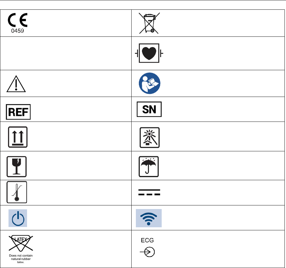
EQUIPMENT SYMBOLS AND MARKINGS
Indicates compliance to applicable
European Union directives
Do not dispose as unsorted municipal waste.
Per European Union Directive 2002/96,
requires separate handling for waste disposal
according to national requirements
Defibrillator-proof type CF applied part
Warning/Caution
Consult accompanying documents
Catalog number for relevant Mortara
part Serial number
This end up
Keep away from sunlight
Fragile, handle with care
Keep dry
Temperature limitation
Direct Current
Power On/Wake Screen
This icon indicates the status of the WLAN
connection
Latex free
Patient Cable Input

16of63
6.
GENERAL CARE
Precautions for S2
Power off and remove the battery from the S2 before inspecting or cleaning.
Protect the S2 from water and other liquids.
Never immerse the S2 in water or other fluids.
Do not drop the S2 or subject to shock and/or vibration.
Do not use organic solvents, ammonia-based solutions, or abrasive cleaning agents that may damage
equipment surfaces.
Precautions for Li-Ion Battery Charger and Cord
Remove the AC power from a Li-Ion Battery Charger before inspecting or cleaning.
Protect the AC power cord and Li-Ion Battery Chargers from water or other liquids.
Never immerse the AC power cords or Li-Ion Battery Chargers in water or other fluids.
Do not subject the Li-Ion Battery Chargers to shock and/or vibration.
Do not use organic solvents, ammonia-based solutions, or abrasive cleaning agents that may damage
equipment surfaces.
Inspection Prior to Clinical Use
Inspect your equipment prior to clinical operation. Do not use the equipment and contact an authorized service
representative for servicing if there are concerns about integrity of the system.
Verify that all cables and connectors are securely seated.
Check the case and chassis of the S2, AC power cord, and Li-Ion Battery Charger for any visible
damage.
Inspect the S2 touchscreen and controls for proper function and appearance.
Inspect the Li-Ion Battery Charger indicator LEDs for proper operation and indication of battery charging
and AC connection.
Inspect patient accessories for any visual damage.
S2 patient input connector - Verify the pins on the patient input connector are all present and are not bent or
damaged in any way. The recessed area for the patient connector should be free from debris and clean. Use
compressed air to remove any debris that has entered into the connector area.
S2 display – Verify there are no deep scratches or physical damage to the S2 telemetry device ’s
display. Inspect the display bezel to ensure it is firmly adhered to the device housing. Contact Mortara
Technical Support if the display or display bezel require replacement.
S2 battery door – Verify the S2’s battery door for proper opening and closing. Inspect the plastic door
assembly for signs of excessive wear or cracking, including the door seal to prevent fluid ingress. Replace
the battery door assembly if necessary.

17of63
GENERAL CARE
S2 Battery Compartment – Inspect the S2’s battery spring contacts and the battery door latching
mechanism for signs of excessive wear. If the battery compartment has been damaged, contact Mortara
Technical Support for assistance.
Battery Charger bay – Inspect the Li-Ion Battery Charger’s contacts and mechanisms for signs of
excessive wear.
Rechargeable Li-Ion Battery – Follow the instructions and note the cautions labeled on the rechargeable
battery. Contact Mortara for replacement.
Device Labeling – Inspect the device labeling for signs of wear and legibility. If the labeling is no longer
clear and legible, contact Mortara Technical Support for assistance.
Cleaning and Disinfecting
This section describes the procedures for cleaning and disinfecting the S2, its sensors and accessories.
WARNING: Follow these instructions to clean and disinfect the S2 and its accessories. Improper cleaning
may cause damage that is not immediately apparent, leading to possible safety hazards, device malfunction,
and/or spread of infectious agents between persons.
Disinfecting agents
The S2 is compatible with the following disinfectants:
Clorox Healthcare® Bleach Germicidal Wipes (use according to instructions on product label), or
a soft, lint-free cloth dampened with a solution of sodium hypochlorite (10% household bleach and water
solution) minimum 1:500 dilution (minimum 100 ppm free chlorine) and maximum 1:10 dilution as
recommended by the APIC Guidelines for Selection and Use of Disinfectants.
Cleaning and disinfecting the S2 monitor
WARNING: Do not immerse the S2 in water or any other fluids. The S2 is not designed to be immersed in
liquid and doing so may result in liquid entering the device leading to possible safety hazards and/or device
malfunction.
CAUTION: Do not steam autoclave, gas sterilize, or irradiate the S2 as these may result in damage to the
device.
WARNING: Ensure the battery door is securely in place when cleaning the S2 to avoid risk of liquid
entering into the device which may lead to a possible hazard and/or device malfunction.
To clean the S2:
1.
Switch off the S2. If on, press and hold the Push-Button button on the right side of the device to turn on the
display screen. Press the configuration key on the touch screen, then select [Shutdown Device].
2.
Disconnect patient cables from the S2.

18of63
GENERAL CARE
3.
Thoroughly wipe the surface of the S2 with a clean, lint-free cloth dampened with water for
general cleaning, or use one of the above recommended agents for disinfection.
WARNING: Do not oversaturate the cleaning cloth. Liquid pooling on the device may enter into
the device possibly leading to a safety hazard and/or device malfunction.
4.
Dry the device with a clean, soft, dry, lint-free cloth.
Cleaning sensors and other accessories
The S2 is compatible with a number of sensors and accessories, each with unique cleaning needs. Follow the
cleaning instructions provided in the directions for use shipped with those items.
WARNING: Do not reuse sensors or accessories indicated as single-patient use; as this may facilitate the
spread of infectious agents between persons.
19of63
GENERAL CARE
WARNING: Always clean and/or disinfect reusable sensors and accessories between patients to reduce the
risk of spreading infectious agents between persons.
Maintenance
The following table shows the recommended maintenance procedures for the S2, patient accessories, and Li-Ion Battery
Charger. The S2 should be serviced once a year by a Mortara authorized service technician; however, it is good practice
to periodically ensure the telemetry device is in proper working order. This can be performed by a clinician or biomed
at the hospital or healthcare delivery organization familiar with the S2 telemetry device, ECG signal acquisition, as well
as general maintenance/calibration of biomedical equipment.
To accomplish these steps in their entirety and verify the correct operation of the system, appropriate patient simulators
or other equipment may be required. Refer to the service manual for further details.
Functionality Procedure
Mechanical Integrity Check for cracks, abrasive edges and other signs of damage.
ECG Telemetry Connect ECG leads to Patient Simulator.
Start a new monitoring session.
Verify that waveforms for all leads are properly shown on the LCD.
Li-Ion Battery Charger Check for cracks, abrasive edges and other signs of damage.
Check that all connectors and AC cord length is unbroken and smooth along its
length.
Verify proper LED indicators during battery charging.
ECG Cables Approved Cleaning Agents
Enzymatic detergent such as ENZOL (US) or CIDEZYME (outside the US).
Distilled water.
Disinfectant solution (such as CIDEX OPA, or a 10% solution of household
bleach (5.25% sodium hypochlorite) in distilled water).
Soft, lint-free cloths and/or soft-bristled brushes.
Protective gloves and eyewear.
Procedure
1.
Remove the battery from the telemetry device.
2.
Put on gloves and protective eyewear.
3.
Prepare the detergent according to the manufacturer's instructions, and also
the disinfectant solution, in separate containers.
4.
Apply detergent to product using a soft, lint-free cloth. If material is dried on,
allow to sit for 1 minute. Do not immerse cable ends or lead wires in liquid as
it can cause corrosion.
5.
Wipe smooth surfaces with the cloth.
6.
Use a soft-bristle brush on visibly soiled areas and irregular surfaces.
7.
Remove detergent from product using cloth dampened in distilled water.
8.
Repeat as necessary.
9.
Apply disinfectant solution on affected area using a soft cloth. Allow product to
sit for 5 minutes.
10.
Wipe excess solution and clean product again with cloth dampened in distilled
water.
11.
Allow 2 hours for drying.
WARNING: Only Mortara authorized service providers should perform servicing of the S2 to ensure that the
correct maintenance and calibration procedures are followed and that the S2 is returned to proper operation.
Refer to Section 1 for a list of technical support and service providers.

20of63
GENERAL CARE
WARNING: Do not use the S2 telemetry device and/or its accessories and parts beyond their product life or
past their expiration date, since performance of these may be degraded leading to inaccurate or misleading
results and/or materials may break down over time releasing substances that may be harmful.
Battery life
The S2 may be powered only using a (1) Rechargeable Li-Ion Battery Pack.. As the battery pack ages, its ability
to store charge is gradually reduced. If the battery pack no longer provides the run time needed, it should be
replaced. (See table below in Chapter 15 – Power Requirements & Battery for operation time)
WARNING: Remove the batteries if the S2 will not be used for an extended period to avoid possible leakage
of harmful substances from the battery.
WARNING: Use only APPROVED BATTERIES and BATTERY CHARGER as listed in the Accessories
section. Use of unapproved batteries may cause a hazard and/or damage the S2, and will void the warranty.
NOTE: Excessive wireless network traffic, signal strength, and network dropouts may affect the battery life.
Product life
The S2 has a defined product life of 5 years excluding accessories, cables and batteries. As required, product service,
accessories and spare parts are available through Mortara or its authorized partners. Using the telemetry device or its
accessories and components beyond their defined life may lead to damage to the equipment or a safety hazard to the
user.
Decommissioning and Disposal
Dispose of the telemetry device, its components and accessories (e.g., batteries, cables, electrodes), and/or packing
materials in accordance with local regulations. Do NOT incinerate the battery.

21of63
7.
ELECTROMAGNETIC COMPATABILITY (EMC)
When using the telemetry device, assess the electromagnetic environment affected by surrounding devices.
An electronic device may either generate or receive electromagnetic interference. Testing for electromagnetic
compatibility (EMC) has been performed on the telemetry device according to the applicable international standards.
The telemetry device should not be used adjacent to or stacked with other equipment. If the telemetry device is used in
this manner, verify the telemetry device operates in an acceptable manner in the configuration in which it will be used.
Fixed, portable, and mobile radio frequency communications equipment may affect the performance of medical
equipment. See the appropriate EMC table for recommended separation distances between the radio equipment and the
telemetry device.
The use of accessories, transducers, and cables other than those specified by Mortara may result in increased emissions
or decreased immunity of the equipment.
ELECTROMAGNETIC COMPATABILITY (EMC)

22of63
Guidance and Manufacturer’s Declaration: Electromagnetic Emissions
The equipment is intended for use in the electromagnetic environment specified in the table below. The customer or the
user of the equipment should ensure that it is used in such an environment.
Emissions Test Compliance Electromagnetic Environment: Guidance
RF Emissions
CISPR 11
Group 2 The S2 must emit electromagnetic energy in order to perform its
intended function. Nearby electronic equipment may be affected
RF Emissions
CISPR 11
Class A The S2 is suitable for use in all establishments other than
domestic and those directly connected to the public low-voltage
power supply network that supplies buildings used for domestic
purposes.
Harmonic Emissions
IEC 61000-3-2
Not Applicable
Voltage Fluctuations/
Flicker Emissions
IEC 61000-3-3
Not Applicable
Guidance and Manufacturer’s Declaration: Electromagnetic Immunity
The equipment is intended for use in the electromagnetic environment specified in the table below. The customer or the
user of the equipment should ensure that it is used in such an environment.
Immunity Test IEC 60601 Test Level Compliance Level Electromagnetic Environment:
Guidance
Electrostatic
discharge (ESD)
EN 61000-4-2
+/- 8 kV contact
+/- 15 kV air
+/- 8 kV contact
+/- 15 kV air
Floors should be wood, concrete, or
ceramic tile. If floors are covered with
synthetic material, the relative humidity
should be at least 30%.
Electrical fast
transient/burst
EN 61000-4-4
+/- 2 kV for
power supply lines
+/- 1 kV for
input/output lines
+/- 2 kV for
power supply lines
+/- 1 kV for
input/output lines
Mains power quality should be that of a
typical commercial or hospital
environment.
Surge
IEC 61000-4-5
+/- 1 kV differential
mode
+/- 2 kV common mode
+/- 1 kV differential
mode
+/- 2 kV common
mode
Mains power quality should be that of a
typical commercial or hospital
environment.
Voltage
fluctuations and
Interruptions
<5% UT for 0.5 cycles
40% UT for 5 cycles
70% UT for 25 cycles
<5% UT for 5s
<5% UT for 0.5 cycles
40% UT for 5 cycles
70% UT for 25 cycles
<5% UT for 5s
Note that monitoring is interrupted at the
level “< 5% UT for 5s”, but equipment
remains safe (as specified in
EN 60601-1-2).
Power frequency
(50/60 Hz)
magnetic field
IEC 61000-4-8
30 A/m 30 A/m Power frequency magnetic fields should
be at levels characteristic of a typical
location in a typical commercial or
hospital environment.
NOTE: UT is the AC Mains voltage prior to application of the test level.
23of63
ELECTROMAGNETIC COMPATABILITY (EMC)
Guidance and Manufacturer’s Declaration: Electromagnetic Immunity
The equipment is intended for use in the electromagnetic environment specified in the table below. The customer or the
user of the equipment should ensure that it is used in such an environment.
Immunity Test IEC 60601 Test
Level
Compliance
Level
Electromagnetic Environment: Guidance
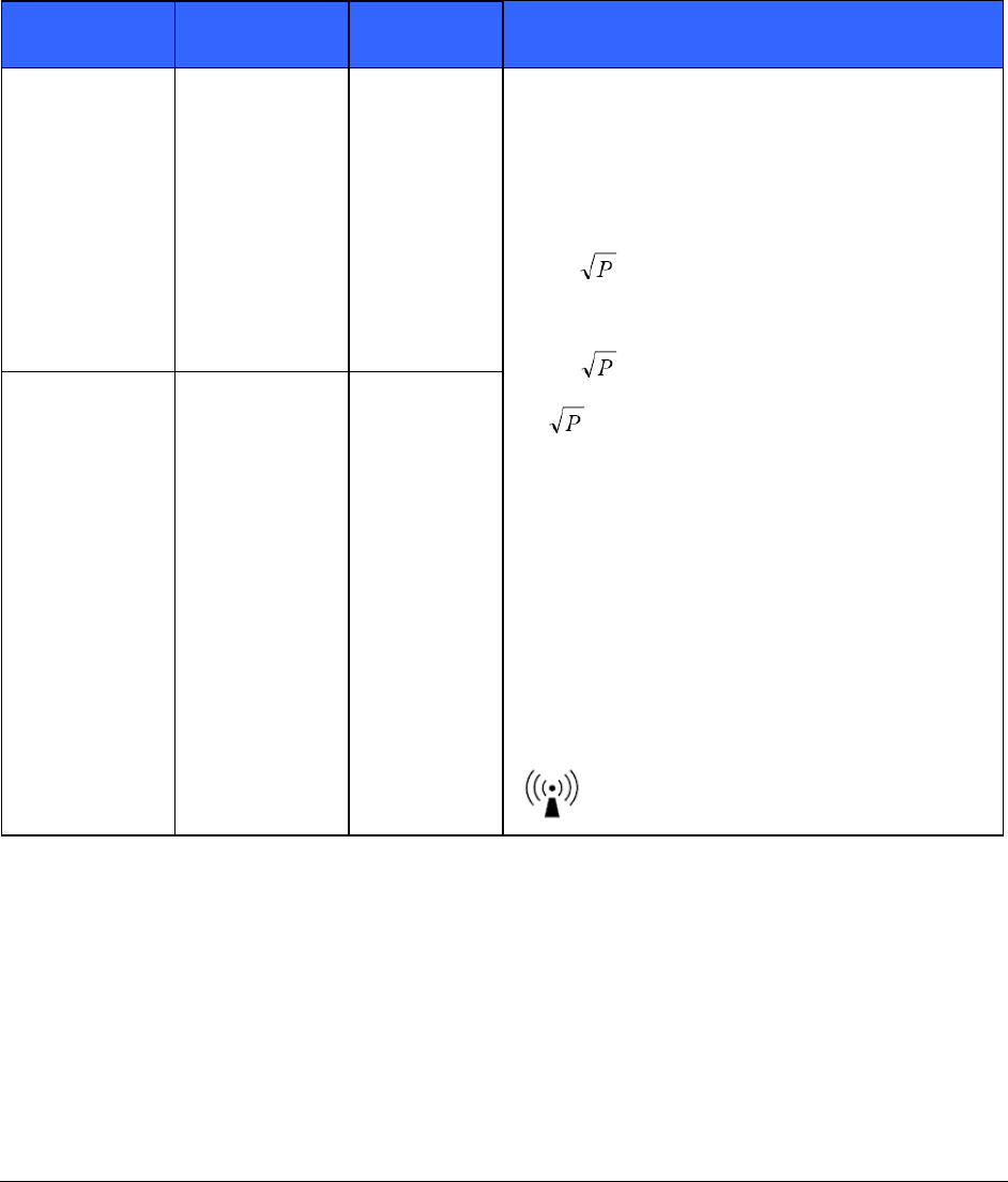
Conducted RF
EN 61000-4-6
3 Vrms
150 kHz to
80 MHz
3 Vrms
150 kHz to
80 MHz
Portable and mobile RF communications equipment
should be used no closer to any part of the equipment,
including cables, than the recommended separation
distance calculated from the equation applicable to the
frequency of the transmitter.
Recommended separation distance
d = 1.2
d = 1.2 80 MHz to 800 MHz
d =
800 MHz to 2.5 GHz
Where P is the maximum output power rating of the
transmitter in watts (W) according to the transmitter
manufacturer and d is the recommended separation
distance in meters (m).
Field strengths from fixed RF transmitters, as
determined by an electromagnetic site surveya, should
be less than the compliance level in each frequency
rangeb.
Interference may occur in the vicinity of equipment
marked with the following symbol:
Radiated RF
IEC 61000-4-3
10 V/m
80 MHz to
2.7 GHz
10 V/m
80 MHz to
2.7 GHz
a.
Field strengths from fixed transmitters, such as base stations for radio (cellular/cordless) telephones and land mobile
radios, amateur radios, AM and FM radio broadcast, and TV broadcast cannot be predicted theoretically with accuracy.
To assess the electromagnetic environment due to fixed RF transmitters, an electromagnetic site survey should be
considered. If the measured field strength in the location in which the equipment is used exceeds the applicable RF
compliance level above, the equipment should be observed to verify normal operation. If abnormal performance is
observed, additional measures may be necessary, such as reorienting or relocating the equipment.
b.
Over the frequency range 150 kHz to 80 MHz, field strengths should be less than [3] V/m.
24of63
ELECTROMAGNETIC COMPATABILITY (EMC)
Recommended Separation Distances Between Portable and Mobile RF
Communications Equipment and the Equipment
The equipment is intended for use in the electromagnetic environment in which radiated RF disturbances are controlled.
The customer or the user of the equipment can help to prevent electromagnetic interference by maintaining a minimum
distance between portable and mobile RF communications equipment (transmitters) and the equipment as recommended
in the table below, according to the maximum output power of the communications equipment.
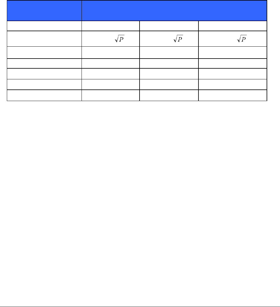
Rated Maximum Output
Power of Transmitter (W)
Separation Distance According to Frequency of Transmitter (m)
150 KHz to 80 MHz 80 MHz to 800 MHz 800 MHz to 2.5 GHz
d = 1.2 d = 1.2 d = 2.3
0.01
0.12 m 0.12 m 0.23 m
0.1 0.38 m 0.38 m 0.73 m
1
1.2 m 1.2 m 2.3 m
10 3.8 m 3.8 m 7.3 m
100
12.0 m 12.0 m 23.0 m
For transmitters rated at a maximum output power not listed above, the recommended separation distance d in
meters (m) can be estimated using the equation applicable to the frequency of the transmitter, where P is the
maximum output power rating of the transmitter in watts (W) according to the transmitter manufacturer.
NOTE: At 80 MHz and 800 MHz, the separation distance for the higher frequency range applies.
NOTE: These guidelines may not apply in all situations. Electromagnetic propagation is affected by
absorption and reflection from structures, objects, and people.

25of63
ELECTROMAGNETIC COMPATABILITY (EMC)
USA and Canadian Radio Regulations
USA (FCC)
This device is equipped with Transmitter Module FCC ID: O7P-341 .
This device complies with part 15 of the FCC Rules. Operation is subject to the following two conditions:
This device may not cause harmful interference.
This device must accept any interference received, including interference that may cause undesired operation.
This equipment has been tested and found to comply with the limits for a Class B digital device, pursuant to Part 15 of
FCC Rules. These limits are designed to provide reasonable protection against harmful interference in a residential
installation. This equipment generates, uses, and can radiate radio frequency energy. If not installed and used in
accordance with the instructions, it may cause harmful interference to radio communications. However, there is no
guarantee that interference will not occur in a particular installation. If this equipment does cause harmful interference to
radio or television reception, which can be determined by turning the equipment off and on, the user is encouraged to try
and correct the interference by one or more of the following measures:
Reorient or relocate the receiving antenna
Increase the distance between the equipment and the receiver
Connect the equipment to an outlet on a circuit different from that to which the receiver is connected
Consult the dealer or an experienced radio/TV technician for help
The user may find the following booklet prepared by the Federal Communications Commission helpful:
The Interference Handbook
This booklet is available from the U.S. Government Printing Office, Washington, D.C.
20402. Stock No. 004-000-0034504.
Mortara is not responsible for any radio or television interference caused by unauthorized modification of the devices
included with this Mortara product, or the substitution or attachment of connecting cables and equipment other than
specified by Mortara.
The correction of interference caused by such unauthorized modification, substitution, or attachment will be the
responsibility of the user.
This device with transmitter module has been tested to SAR and complies with FCC exposure requirements for
portable devices. SAR testing has been done at a distance of 0 mm from the body.
CANADA (ISED)
This device complies with Industry Canada's license-exempt RSSs. Operation is subject to the following two
conditions: (1) This device may not cause interference; and (2) This device must accept any interference, including
interference that may cause undesired operation of the device. Le present appareil est conforme aux CNR d'industrie
Canada applicable aux appareils radio exempts de licence. L'exploitation est autorisee aux deux conditions suivantes:
(1) l'appareil ne doit pas produire de brouillage, et (2) l'utilisateur de l'appareil doit accepter tout brouillage
radioelectrique subi, meme si le brouillage, est susceptible d'en compromettre le fonctionnement.
infere

26of63
8.
INTRODUCTION
General Information
This user manual provides information for users of the Mortara Surveyor S2 telemetry device and its related
components. It is written for clinical professionals expected to have a working knowledge of medical procedures and
terminology as required for monitoring cardiac patients.
The Surveyor S2 telemetry device is a small, lightweight device designed to acquire an ECG and transmit this data to a
MONITORING NODE.
This user manual explains:
Relevant safety cautions, warnings and notices.
How to configure, use and maintain the S2 telemetry device as well as its components and accessories.
How to change the device configuration to adapt to the hospital IT network environment.
How to properly acquire and transmit patient ECG signals to a MONITORING NODE.
Please also refer to the MONITORING NODE user manual for additional information.
WARNING: The Surveyor S2 telemetry device by itself is not intended to be used as a vital signs
physiological monitor.
CAUTION: The Surveyor S2 is has not been designed for direct cardiac applications involving direct contact
with a patient’s heart.
CAUTION: The Surveyor S2 has not been designed to be used together with electrosurgery equipment.
NOTE: This manual may contain renderings of various display screens. Any screen images are provided for
reference only and are not intended to convey actual operating techniques.
Indications For Use
The Surveyor S2 is indicated for use in adult, adolescents, and children patient populations. The Mortara
Surveyor S2 facilitates the monitoring of ECG signals.
The Surveyor S2 is a prescription device intended to be used by knowledgeable healthcare professionals within a
healthcare facility or clinical pharmacology unit.
The Surveyor S2 is indicated for use in a clinical setting by a physician, or by trained personnel acting on the
orders of a licensed physician. It is not intended as a sole means of diagnosis.
The Surveyor S2 is indicated for use as a radiofrequency physiological signal transceiver, receiving and delivering
real-time acquisition and transmission of simultaneous electrocardiographic data, while allowing the patient to be
ambulatory within the range of the antenna network.
The Surveyor S2 is indicated for use to acquire and output electrocardiographic data.
27of63
System Overview
The S2 telemetry device provides a means to acquire and transmit simultaneous ECG data to a MONITORING
NODE while allowing the patient to be ambulatory within the coverage range of the WLAN network.
The S2 uses one (1) rechargeable battery pack.
The following equipment is necessary to use the S2:
One (1) Rechargeable Li-Ion Battery Pack
Applicable patient cable, lead wires, and electrodes.
Carrying pouches.
Battery charger.
Customer provided 802.11 a/b/g/n 2.4 GHz (a/g/n is recommended) or 5 GHz wireless access points and network
infrastructure.
MONITORING NODE monitoring system.
Available configurations
The S2 is offered in the following, factory-set parameter configurations:
4-wire ECG
28of63
INTRODUCTION
4-wire ECG
When configured with the 4-wire ECG port, the S2 provides cardiac telemetry using a shielded 4-wire ECG cable.
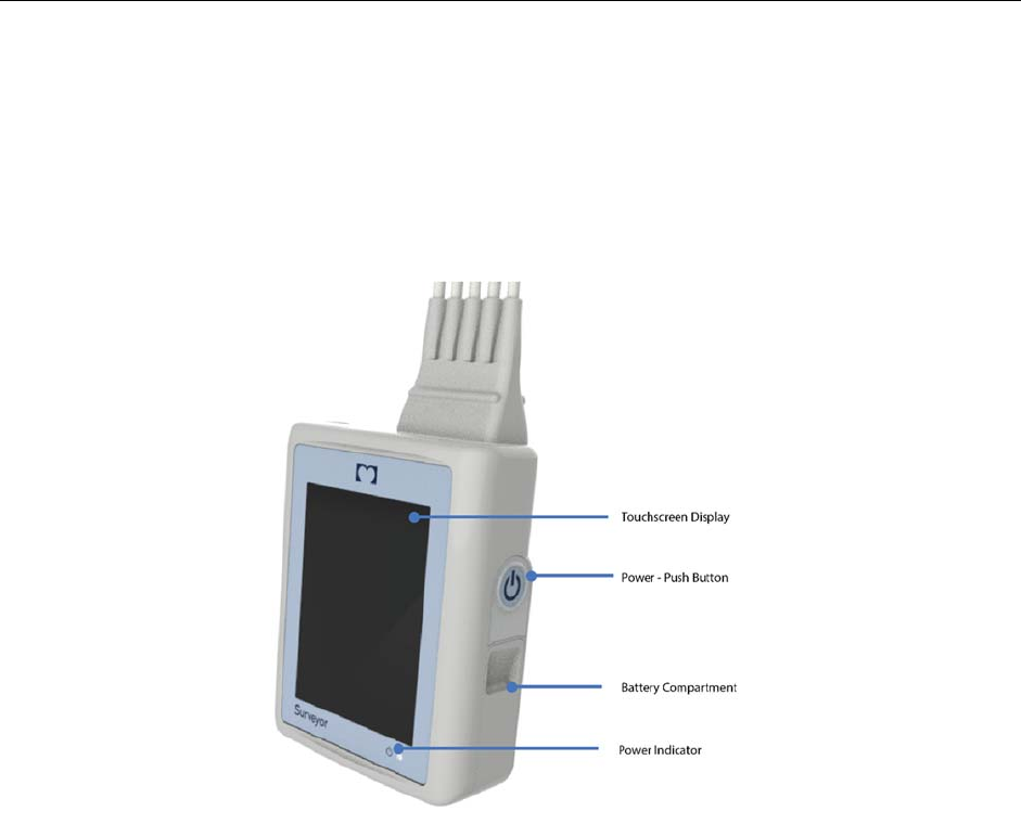
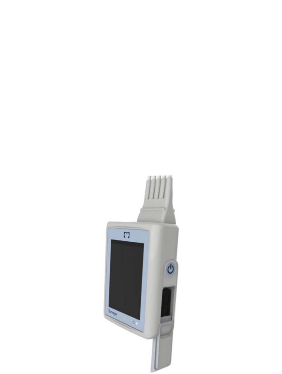
Operating controls and indicators
The operating controls and indicators of the S2 are shown in the following diagram:
Display Screen
Screen allows for display of icons, menus, waveforms, and other device, patient, and status information.
The S2 uses a touchscreen user interface for operator interaction which allows control over the device via selection
of menu items and icons as well as entry of relevant configuration and patient information by pressing on the screen.
29of63
Power Push-Button
By pressing and holding this button once, it turns the S2 device on. The Waveforms Screen should display by
default.
After 60 seconds of inactivity the device will enter a low power state where the display will turn off. In this state,
the display screen will be off but the functionality (i.e. ECG telemetry) will continue. To turn the display back on,
hold the Power Push-Button.
Power Indicator
This bi-color LED will indicate these conditions in the following priority :
1. Flash green rapidly when: Device On, not Connected (Online or Offline)
2. Flash yellow when: Device On, any ECG lead in fail
3. Flash green slowly when: Device On and Connected
Battery Compartment
This section of the device stores the Li-Ion battery.
The S2 device is designed to operate on a single rechargeable Li-Ion battery.
The battery is replaceable without the operation of a tool.
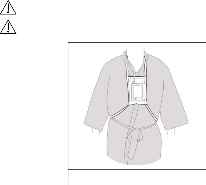
Carrying Pouches
The pouches are designed to fit the contours of the S2 and accommodate extended wearing of the device while the
patient is ambulatory or stationary. The transparent film allows viewing of the screen.
CAUTION: Pouches are designed for single patient use, and should NOT be reused.
CAUTION: While the adhesive pouches are made of biocompatible material and contain no latex, they
should NOT be applied directly to the patient’s skin.
Tie-On Pouch
Ref #: 8485-029-51
30of63
INTRODUCTION
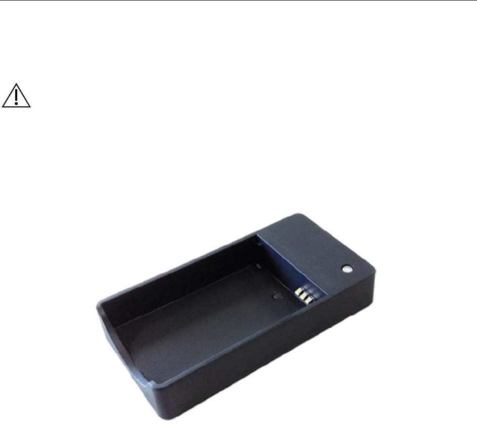
Battery Charger
The following Li-Ion Battery Charger RRC-SCC1120 – Single Cell Charger 1120 can be used to charge the
rechargeable Li-Ion Batteries.
WARNING: To avoid the risk of electric shock, battery chargers must be connected to a supply main
with protective earth.
To charge rechargeable Li-Ion batteries, load a battery into an open battery bay. The battery fits snugly in its
charging bay in only one orientation, It snaps in place when slid down onto the charging contacts on the battery
bay.
The LED on the battery charger indicate the status of the battery charging: Orange light indicates that the inserted
battery is of the corrects type and is currently being charged; Green light indicates that the battery is charged and
can be removed for use; Red blinking indicates battery detection phase; Red light indicates no battery inserted,
battery over/under temperature, charger over temperature battery over voltage, battery charge timer time-out-error
or input voltage too low.

31of63
9.
UNPACKING AND SET UP
Checking Contents
Your S2 is shipped with the following components:
Surveyor S2 Telemetry device
Li-ion rechargeable battery
DVD containing the S2 User Manuals
The following optional S2 accessories are available separately:
Pouch Options:
o
Disposable Tie-On Pouch
Battery Charger
32of63
UNPACKING AND SET UP
Battery Installation
NOTE: If using the S2 rechargeable Li-ion battery, ensure it is fully charged prior to first use.
The battery compartment is accessible via the removable battery door on the right side of the device.
1.
Remove the battery door by firmly pushing down along the groove of the door and remove.
2.
Load the battery into the battery compartment:
Align the battery so that once it is slid into place it
adheres with the contacts
a.
Insert the battery into the compartment and
slide to lock it mechanically in place.
3.
Replace the battery door. As shown below, align the wedges of the door with the grooves of the S2 then
push it into place until it is sealed completely.

33of63
10.
PATIENT PREPARATION FOR QUALITY ECG
Quality ECG Data Acquisition
Obtaining quality ECG data is important in continuous ECG monitoring. A quality ECG signal depends largely on
the patient prep and electrode placement. Good contact between the electrodes and the patient's skin and correct
placement of the electrode can help ensure obtaining quality ECG data.
A good quality ECG contains:
Clearly discernible P waves, QRS complexes, and T waves.
Steady, even, crisp baseline.
Absent of respiratory variability, artifact, noise, and other interference.
A good quality ECG may enhance the performance of the Monitoring Node and may lessen false erroneous alarm
notifications.
A poor quality ECG may be caused by many factors:
Poor site preparation.
Poor electrode application or failure to refresh electrodes regularly.
Patient movement.
Interference by other equipment in the room.
Poor quality ECG becomes synonymous with artifact and interference in the ECG waveforms.
A poor quality ECG may manifest in several ways:
Fast baseline artifact.
Erratic baseline.
Sharp “spikes.”
Rolling, wandering waveforms as seen with patient breathing patterns.
Difficult to discern P waves or atrial fib waves from noise.
Inability to discern P waves, QRS complexes, T waves.
Artifact and interference in the ECG waveforms may be caused by using accessories, lead wires, and ECG cables
other than those specified to work with the S2. Always use accessories, lead wires, ECG cables, and other
accessories specified to work with the S2.
Skin Preparation
In continuous ECG monitoring, the goal of skin preparation is to minimize the contact resistance between the
patient’s skin and the ECG electrode. Follow the facility’s standard of care when preparing the patient’s skin for
ECG electrode placement and ECG monitoring.
To prepare the patient’s skin for electrode placement:
1.
Explain the procedure to the patient.
2.
Maintain patient privacy during skin prep and electrode placement.
3.
Locate the correct anatomical landmarks for electrode placement.
4.
Clip or shave excess hair in the areas marked for electrode placement.
5.
Remove residual skin oils, creams, and lotions by gently abrading the skin with a small gauze pad.
NOTE: With elderly or frail patients take care to not abrade the skin causing discomfort or bruising.
Clinical discretion should always be used in patient preparation.

34of63
PATIENT PREPARATION FOR QUALITY ECG
Electrode Placement
To apply electrodes:
1.
Use pre-gelled, Ag/AgCl disposable electrodes.
a.
Do not use electrodes after their expiration date, or if the gel has dried out.
Store electrodes in an air tight container.
Electrodes dry out if not stored properly leading to loss of adhesion and conductivity.
b.
Always use the same electrodes. Do not mix electrode brands or types. Using different types of
electrodes may cause baseline artifact and noise in the ECG tracing.
2.
Apply the electrodes in the following manner:
a.
Attach the electrode to the ECG lead wires prior to attaching the electrode to the patient’s chest.
b.
Place the electrode in the properly prepared, correct location by using a circular motion on the
electrode adhesive area.
c.
Gently press the electrode adhesive to the patient’s skin until the entire outer surface of the electrode is
adhered to the patient’s chest.
d.
Once the electrode adhesive is attached, gently press on the gel area to ensure proper gel to chest
contact. Avoid dislodging the gel as the displaced gel can increase baseline artifact and noise in the
ECG tracing.
e.
Test for firm electrode contact by slightly tugging on the electrode to check for adhesion among the
entire electrode surface. If the electrode moves freely, change the electrode. If the electrode does not
move easily, a good adhesive contact has been obtained.
Refer to the Electrode Location section below for further details on correct anatomical landmarks for electrode
placement.
Best Practice Recommendation: Change electrodes as per hospital standard of care, or at least every 24 hours to
enhance patient skin care and the acquisition of quality ECG data. Clinical discretion should always be used in patient
preparation.
35of63
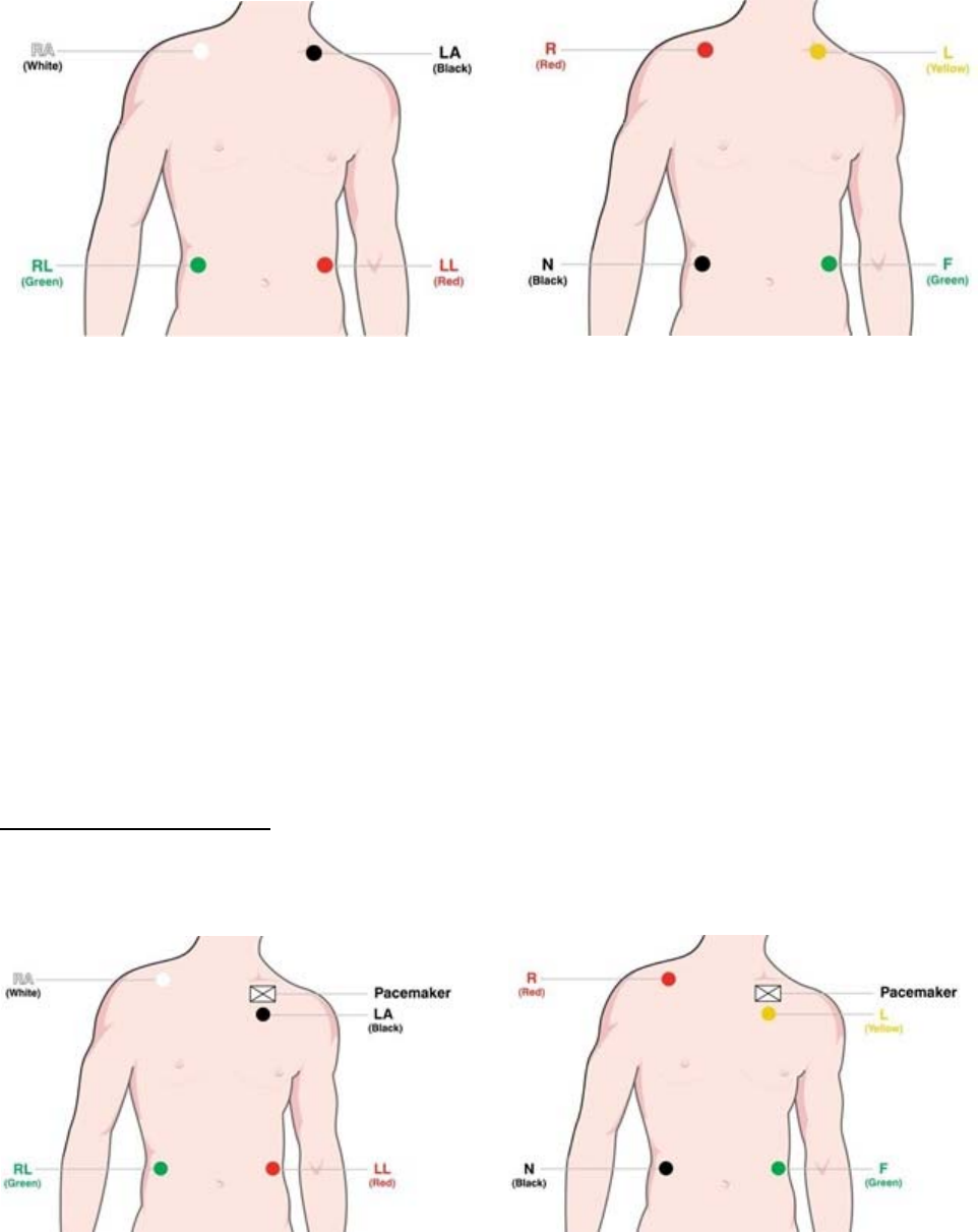
Electrode Locations for 4-Wire Cable
4-Wire Lead Placement (AHA) 4-Wire Lead Placement (IEC)
Place the RA (white) electrode under the patient’s
right clavicle, at the midclavicular line within the rib
cage frame.
Place the LA (black) electrode under the patient’s
left clavicle, at the midclavicular line within the rib
cage frame.
Place the LL (red) electrode on the patient’s lower
left abdomen within the rib cage frame.
Place the RL (green) electrode on the patient’s lower
right abdomen within the rib cage frame.
Place the R (red) electrode under the patient’s right
clavicle, at the midclavicular line within the rib
cage frame.
Place the L (yellow) electrode under the patient’s
left clavicle, at the midclavicular line within the rib
cage frame.
Place the F (green) electrode on the patient’s lower
left abdomen within the rib cage frame.
Place the N (black) electrode on the patient’s lower
right abdomen within the rib cage frame.
Pacemaker Patients
Pacemaker patients may require a modified electrode placement based on the physical location of the patient’s
pacemaker generator device. Do not place an ECG electrode directly over the pacemaker generator as this may lead
to artifact and noise on the ECG tracings.
Best Practice Recommendation: Place the electrode patches 3 – 5 from the pacemaker generator area. For example,
if the pacemaker generator is located in the left subclavian area, relocate the Left Arm electrode closer in towards the
center of the chest.
Use the following lead placement for monitoring a pacemaker patient using 4-wire cable:
4-Wire Lead Placement for Pacemaker Patients
(
AHA
)
4-Wire Lead Placement for Pacemaker Patients
(
IEC
)

36of63
PATIENT PREPARATION FOR QUALITY ECG
Checking ECG Electrode and Lead Wire Signal Quality
Once the patient has been properly prepared, the electrodes have been attached in the correct anatomical location,
and the patient ECG cable is connected to the S2, the S2’s ECG screen displays the patient’s ECG tracings.
Check to ensure the ECG tracing is free of artifact and noise with a clean ECG baseline as patient condition permits.
Refer to the Operation chapter of this user manual to check the quality and waveforms for each lead. If the ECG
contains artifact or noise, review the steps for proper electrode site preparation and placement and repeat these steps
to obtain proper ECG signals.

37of63
11.
OPERATION
Powering On the S2
To power ON the S2, place batteries in the unit as described in Chapter 9.
Press and hold the Power Push-Button on the right side
The power indicator will be lit green
The display will flash blue momentarily and then display the Waveforms screen
Screen Time-Out & Reactivation
To preserve power and to protect against accidental activation of menus, the display will turn off
after 60 seconds of inactivity.
To reactivate the display, press and hold the power Push-button until the screen is activated.
Powering Off the S2
To power OFF the S2, you can either remove the batteries or access the shutdown menu from the settings menu*.
In the latter case, the shutdown menu also stops any active monitoring of telemetry data from the S2 on the
MONITORING NODE.
WARNING: Powering off the transmitter may terminate the monitoring of the patient and cease all
alarms. Ensure that the patient is properly discharged or otherwise cared for prior to powering off the
S2.
38of63
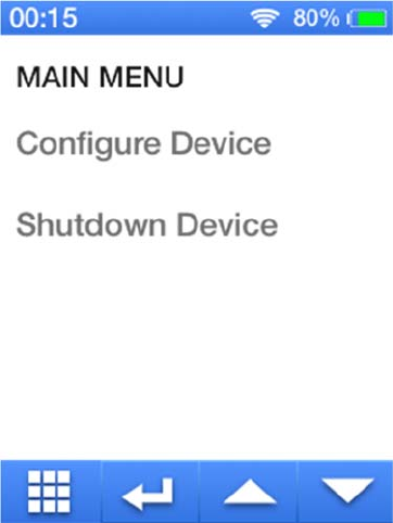
Main Menu Screen
The following diagram shows the general layout of the S2’s main functional screens:
Status Bar
The top portion of the Main Screen is the Status Bar. The remainder of the Main Screen shows one of the following
functional displays:
Configure Device Option: upon tapping on “Configure Device” active area, the device shall switch to
Passcode Screen before proceeding to the Main Configuration Screen.
Shutdown Device Option: upon tapping on “Shutdown Device” active area, the device shall switch to
Passcode Screen before proceeding to Shutdown the device.
Navigation Bar buttons appear along the bottom of the screen, as appropriate to each display screen.
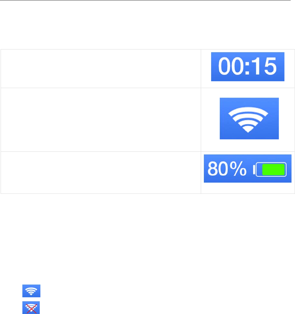
39of63
OPERATION
Status Bar Area
The top portion of the LCD screen shows status information regarding the current state of the device. It displays the
(1) Time of Day, (2) WLAN and Connection Status, in addition to the (3) battery status as described below:
(1)
Time
The following information is shown:
Displays the time of day in 24H format without seconds, as received
from MONITORING NODE.
(2) WLAN Connection Status
The following information is shown:
When connected to WLAN, the status bar shall include an
indication of the level of the signal.
When not connected to WLAN, the status bar shall display an
indication in place of Signal Level and Communication Status
(3) Battery Capacity Status
The status bar shall display the remaining battery capacity in
percentage.
Time of Day
The current time of day is displayed on the top of the status area. The current date and time is synchronized between
the S2 and the MONITORING NODE. If the connection between the MONITORING NODE is disrupted or the S2
battery removed the time information is resynchronized on the next connection to the MONITORING NODE.
WLAN Connection Status
The battery level indicator in the Status Bar Area displays one of the following symbols depending on the status of the
WLAN Connection
The device was successful in establishing a connection to the wireless network.
The device was not successful in establishing a connection to the wireless network.
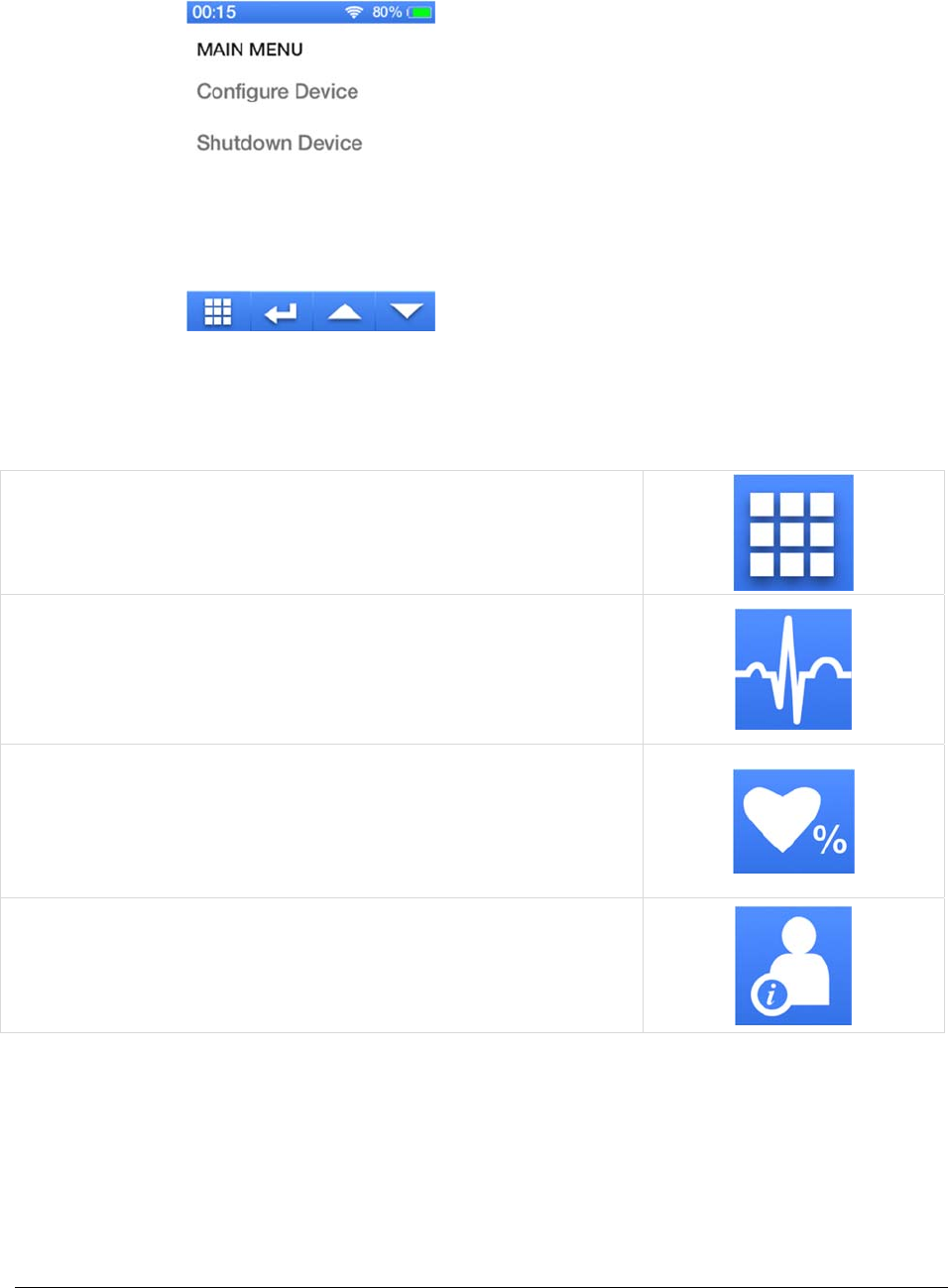
40of63
Navigation Bar
Navigation Bar Area
The bottom portion of the LCD screen contains the bar for switching between Monitoring Screens. It
contains the (1) Main Menu Screen, (2) Waveform Screen, (3) Parameters Screen and (4) Demographics
Screen as described below:
(1)
Main Menu Button
Upon tapping on the Main Menu Screen Button, it will bring you
to the Main Menu Screen
Here you will be able to shut down the device or configure it
(2) Waveform Button
Upon tapping on the Waveform Button, it will bring you to the
Waveform Screen
Here you will be able to view the ECG waveform
(3) Parameters Button
Upon tapping on the Parameters Button, it will bring you to the
Parameters Screen
Here you will be able to view the Heart Rate of the patient at a
glance
(4) Demographics Button
Upon tapping on the Demographics Button, it will bring you to
the Demographics Screen
Here you will be able to view the patient’s information
OPERATION
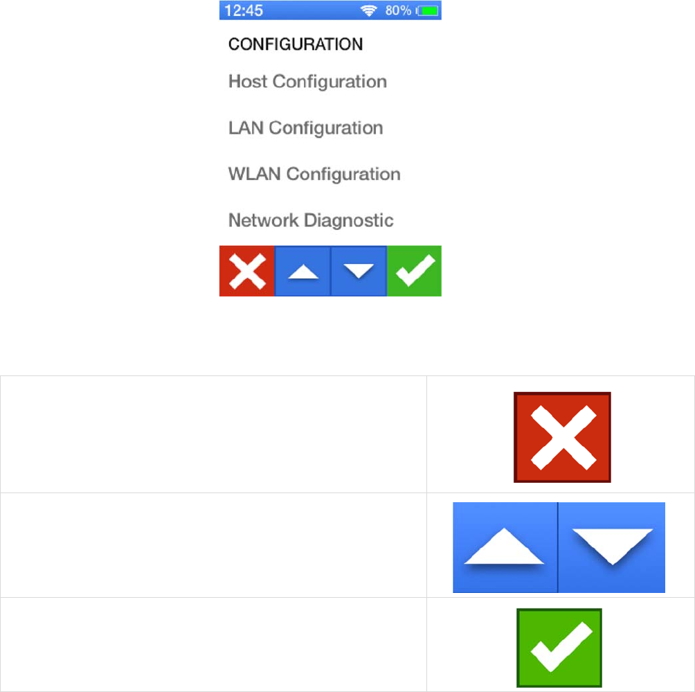
41of63
Main Configuration Screen
Located on the bottom of the Main Configuration Screen is the Configuration Navigation Bar. In this Configuration
Navigation Bar, it contains buttons that will (1) Cancel, (2) Up and Down Buttons and (3) Confirm the actions made
during the time of entering the Main Configuration Screen.
(1) Cancel Button
Upon tapping on the Cancel Button, it shall discard all changes
and switch back to the Main Menu Screen
(2) Up and Down Buttons
Upon tapping on these buttons, it shall scroll the current
area content in a per page fashion, in case not all elements
can fit in a single pagearea.
(3) Confirm Button
Upon tapping on the Confirm Button, it shall store and apply
all changes through an automatic reboot. If there are no
outstanding changes then it will simply return to the Main
Menu Screen.
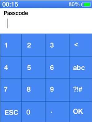
42of63
In order to get to the Main Configuration Screen, you have to input the correct passcode when prompted on the Passcode
Screen pictured below.
The default passcode for the S2 device is 7865.
The ESC button is pressed to cancel data entry and go back to the parent screen
The OK button is pressed to confirm data entry to go back to the parent screen or proceed to the next screen
The < (backspace button) is pressed to delete the last character in the entry
Upon entering the correct Passcode, it will proceed to the Main Configuration Screen. Here, you will be able to configure
the S2 device in these respective fields, (1) Host Configuration, (2) LAN Configuration, (3) WLAN Configuration and
view information such as (4) Network diagnostic, (5) Device diagnostic, and (6) Version.
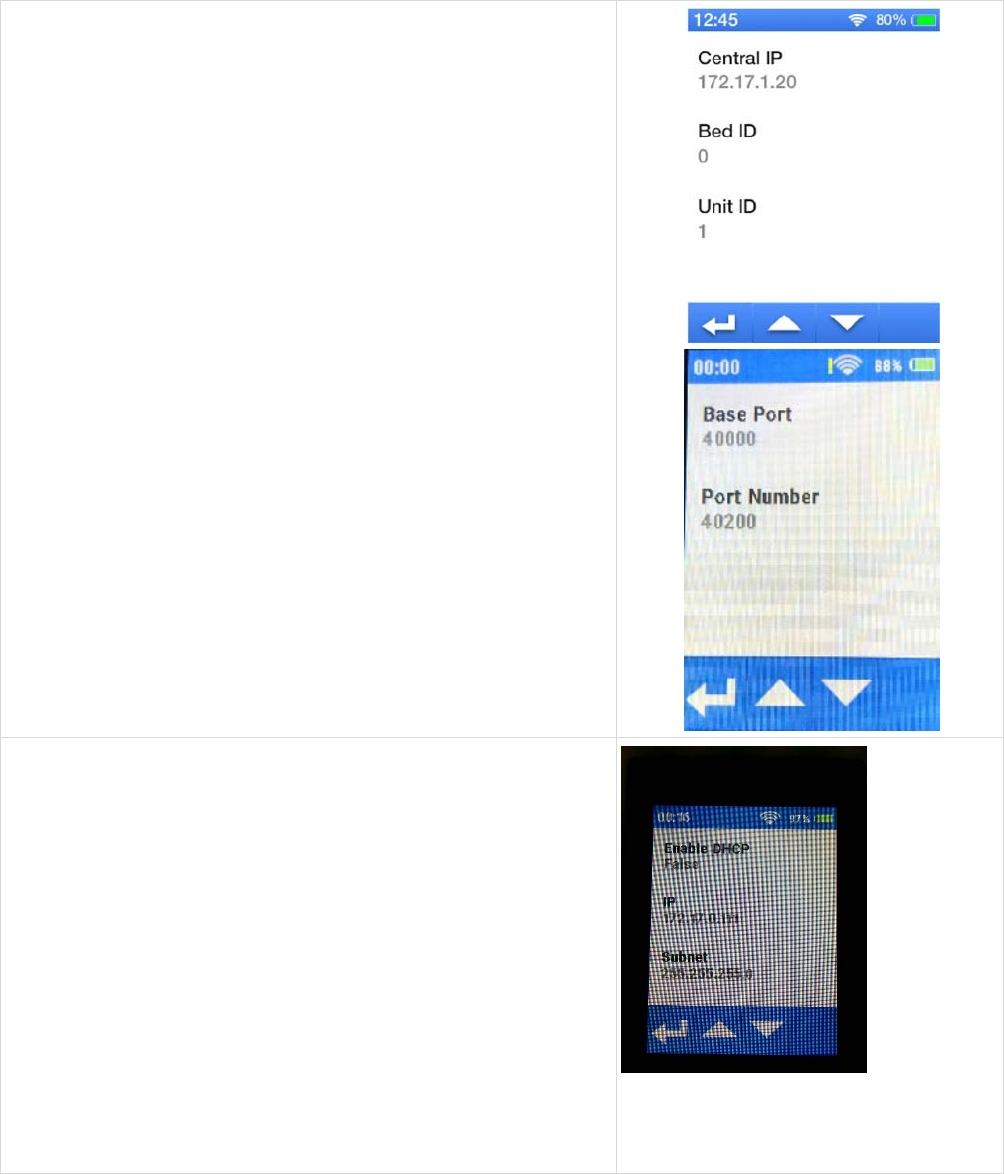
43of63
(1) Host Configuration
Upon tapping on the Host Configuration area, it will proceed
to a Host Configuration Screen.
In this view, you will be able to edit the following:
• Central IP
• Bed ID
• Unit ID
• Base Port
• Port Number
(2) LAN Configuration
Upon tapping on the LAN Configuration area, it will proceed
to a LAN Configuration Screen
In this view, you will be able to edit the following:
o Enable DHCP
If this setting is set to true then the following
settings are NOT able to be edited
IP
Subnet
Gateway
If this setting is set to false then the
following are able to be edited
IP
Subnet
Gateway
Pictured here is an example of when the
“Enable DHCP” is enabled. The other
fields are then editable.
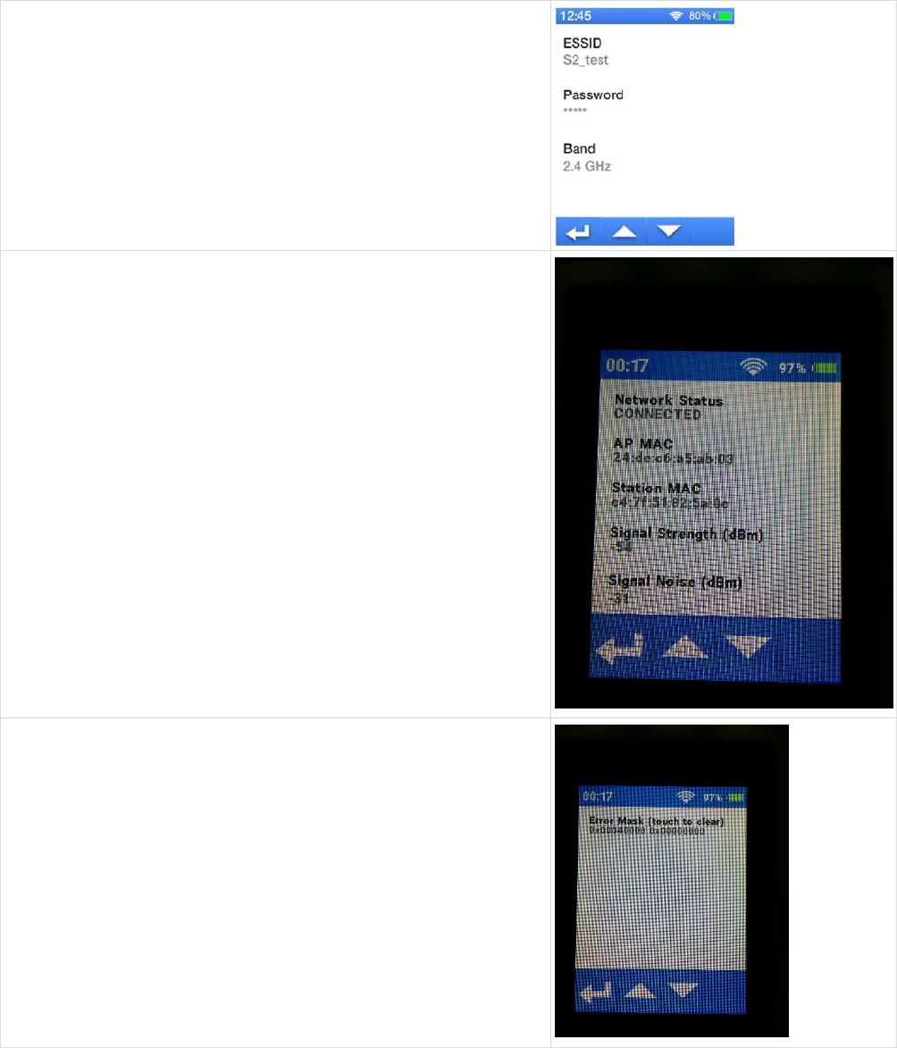
44of63
(3) WLAN Configurations
Upon tapping on the WLAN Configuration area, it will
proceed to a WLAN Configuration Screen
In this view, you will be able to edit the following:
o ESSID
o Passkey
o Band
This is a toggle to allow the user to switch
between 2.4Gz and 5Gz
(4) Network Diagnostics
Upon tapping on the Network Diagnostics area, it will
proceed to a Network Diagnostics Screen
In this view, you will be able to view the following
information:
o Network Status
o IP Address
o AP MAC
o Station MAC
o Signal Strength
o Signal Noise
o Quality
o Channel
o Error
o Current ESSID
(5) Device Diagnostics
Upon tapping on the Device Diagnostics area, it will
proceed to a Device Diagnostics Screen
In this view, you will be able to view if an error occurred and
be able to clear it

45of63
(6) Version
Upon tapping on the Version area, it will proceed to a
Version Screen
In this view, you will be able to view the current version of
the device
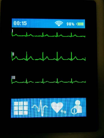
46of63
Waveform Screen
When initially powered on, the S2 will default to the Waveform Screen. It begins monitoring right away.
Main Waveforms Screen
In the monitoring screen, the S2 displays the on-demand ECG waveforms as follows:
1)
The S2 is capable of displaying derived ECG leads depending on the type of ECG cable attached
• When a 4-wire cable is in use, the S2 is capable of displaying Leads I, II, and III.
2)
The ECG waveform(s) is green in color.
3)
The ECG waveform(s) will be drawn as a square wave when in lead fail.
4)
The S2 displays a minimum 3 seconds of the ECG waveform(s)
5)
ECG waveform(s) displayed is high pass filtered
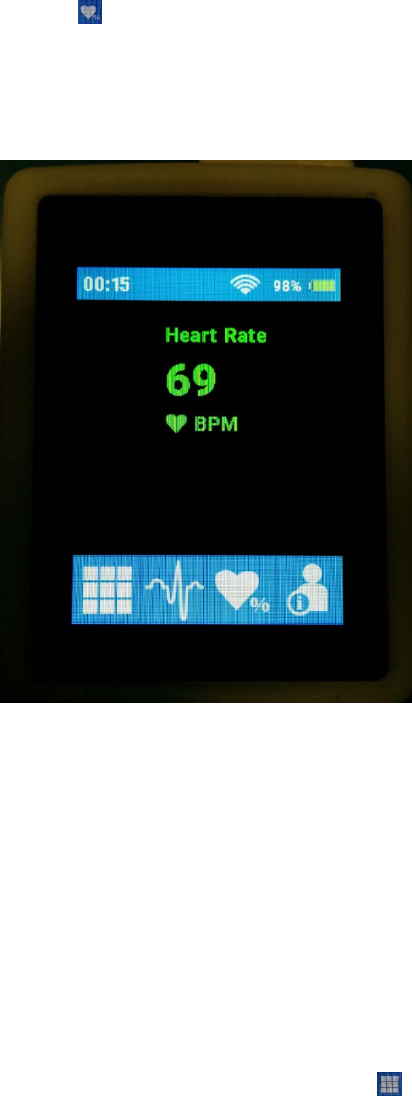
47of63
Parameters Screen
When the S2 is in an active session, it is possible to display the patient’s heart rate by pressing the Parameters
Icon in the Navigation Bar
Parameters Screen
This will show the patient’s current heart rate as reported by the MONITORING NODE.
NOTE: By design, no other parameters or alarms are shown on the S2’s display. Refer to the
MONITORING NODE user manual for relevant parameters, alarms and other information available
there.
Parameters Icons
1. The Heart Rate will display “???” when there is an INVALID parameter
2. The Heart Rate will display “?” when the parameter has EXPIRED
3. The Heart Rate will display “---“ when the parameter is DISABLED
4. The Heart Rate as received from the MONITORING NODE will be displayed together with “bpm”
unit of measure.
To return to the main screen, press the Main Menu Icon
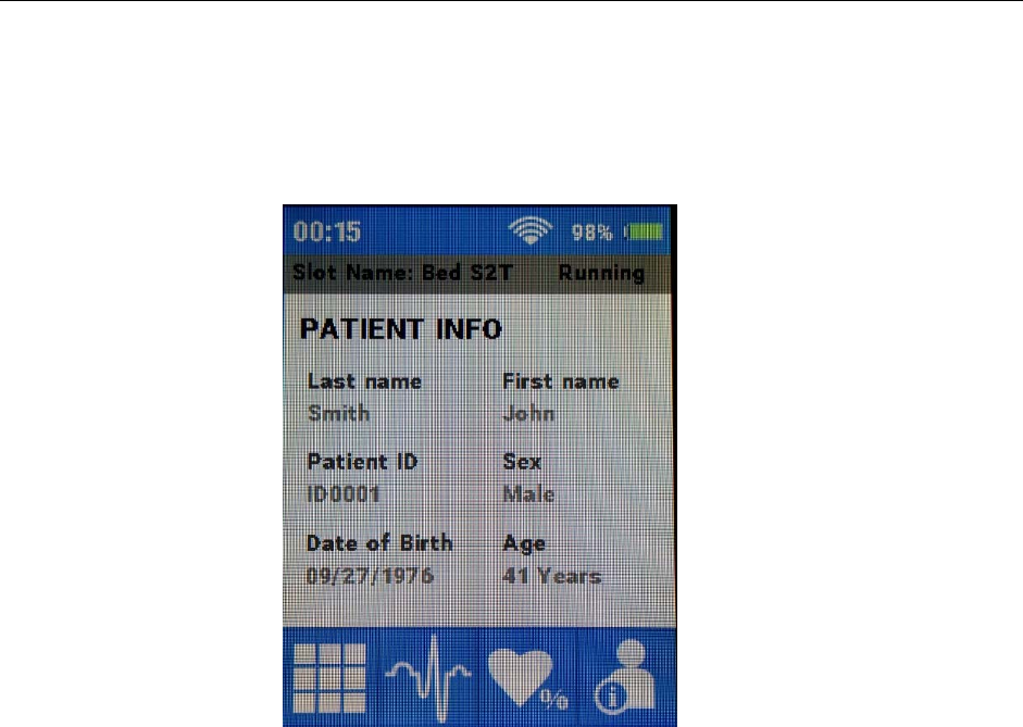
48of63
OPERATION
Demographics Screen
When the S2 is in an active monitoring session, it is possible to receive information from the MONITORING NODE
about the demographics of the patient.
Parameters Screen
The following information will be displayed on the Main Area for sessions assigned to the patient and are acquired from
the MONITORING NODE
1. First Name
2. Last Name
3. Patient ID
4. Date of Birth
5. Age
6. Sex
Demographics information will be replaced by “Anonymous” if no patient is assigned to the monitoring session.
The Status of the monitoring session (Running or Stopped) will be indicated as well as the bed/slot name.
The Age will be displayed in one of the following units of measurement:
1. Years
2. Months
3. Weeks
4. Days
Demographics not received for more than 50 seconds will be considered EXPIRED and all the fields will be replaced by
“?”.
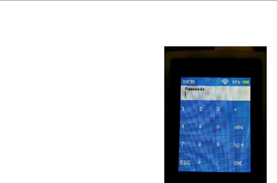
49of63
12.
CONFIGURING THE S2
This chapter describes how to configure the S2 including changing the settings during the operation as well as
general configuration for setup of the S2.
Passcode Entry Screen
Select the configuration area settings when inside the
Main Menu Screen.
NOTE: This particular screen is a password-
protected function and only available through a
passcode. The S2 is factory shipped with passcode
7865. Refer to your facility’s administrator for
additional information.
Upon entry of the passcode, the menus for this screen
will be available. If the wrong passcode is entered, the
“Unlock failed” message is displayed and the correct
passcode must be entered to enter this screen.
Alternativel
y
, this operation ma
y
be cancelled.
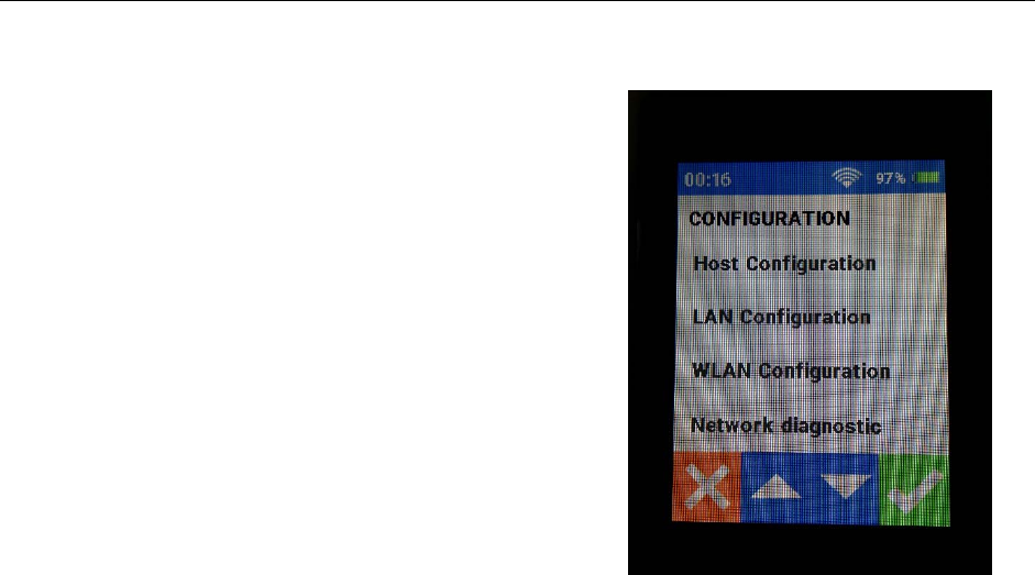
50of63
CONFIGURING THE S2
Configuration Settings Screen
Upon successful entry of the passcode, the S2 is
unlocked and the configuration settings screen is
displayed as shown.
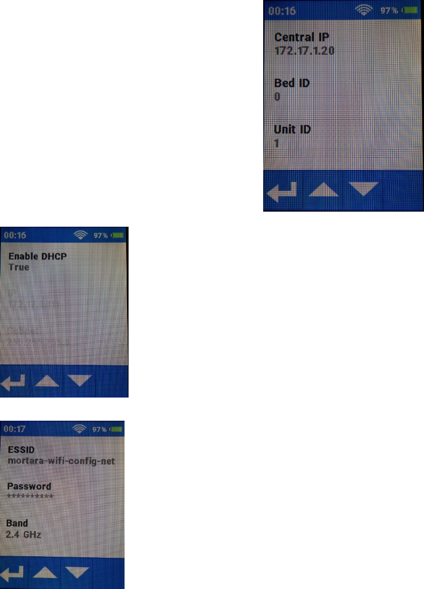
51of63
Host Settings
Host Settings Screen
The settings for the MONITORING NODE including its
IP address, and the unit and bed ID for this particular S2,
as well as base IP port and IP port number are defined
here. If you are uncertain about these settings, please
consult Mortara or
y
our IT Networ
k
Administrator.
Network Settings
The network settings of the S2 are configured as shown below.
Network Settings Screen
LAN
WLAN
52of63
Available settings include:
LAN
• IP Address Method: Whether dynamically assigned by the network through a DHCP
service or manually assigned here to a static address. If “False” is selected, the IP address,
subnet mask and gateway address must be defined.
WLAN
• SSID, Band, & Passkey: The SSID and Passkey of the WLAN network that will be used
for telemetry transmission.
If you are uncertain about these settings, please consult Mortara or your IT Network Administrator.
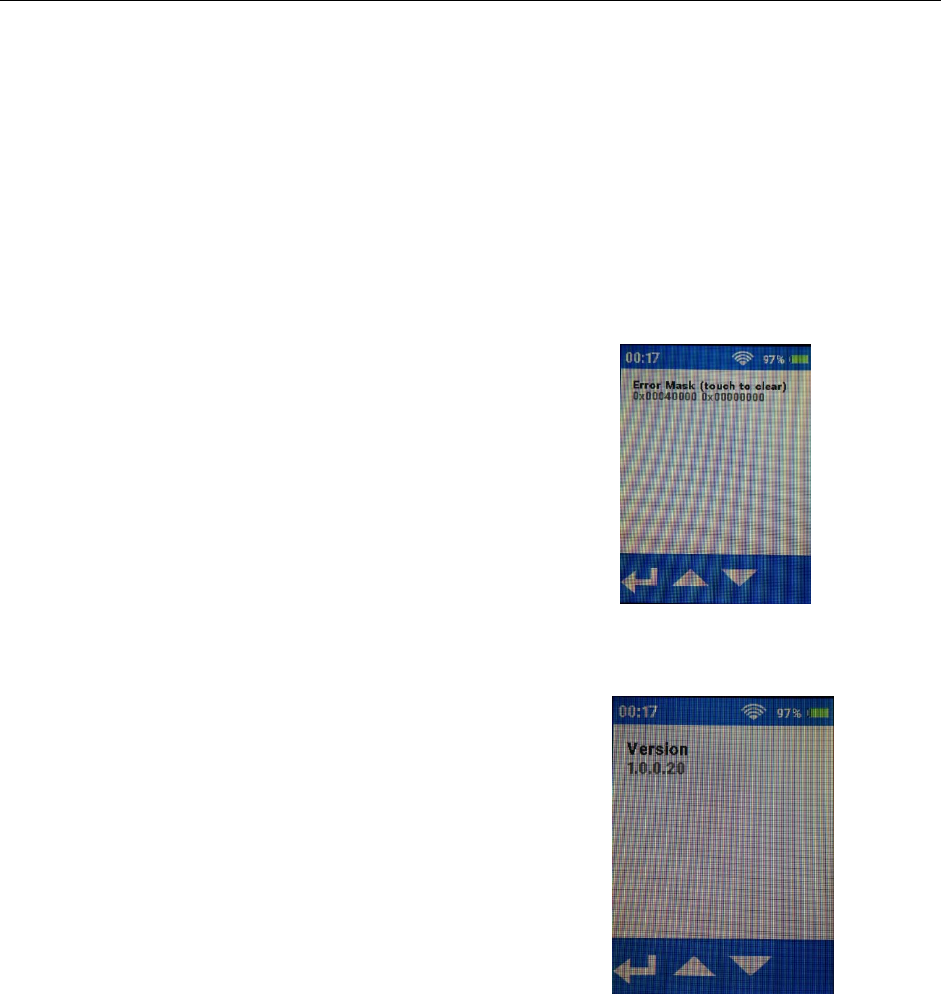
53of63
CONFIGURING THE S2
Language Settings
The S2’s user interface supports only the English
lan
g
ua
g
e as of now.
Device Diagnostics
Device Diagnostics Screen
This device diagnostics screen provides an easy access
method to determine the current state of the device. It
quickly assesses if the device has a current error as well
as clear previous errors.
S2 Version
S2
V
ersion Screen
This screen displays the current version of the S2
software. In case of problems or issues, it may be
necessary to share this information with Mortara.

54of63
13.
ECG MONITORING
To perform ECG acquisition on a patient using the S2 and MONITORING NODE:
Power-On
1.
Insert freshly charged rechargeable batteries in the device.
2.
Press the Power On button to power up the S2.
Patient Prep
3.
Prep the patient and place electrodes per clinical guidelines
and provided instructions.
Patient Cable Hookup
4. Attach the patient cable to the electrodes on the one end, and to
the S2 on the other end.
ECG MONITORING
Confirm Good Signal
4.
Confirm that all leads are OK. Select the waveforms icon ( ) to
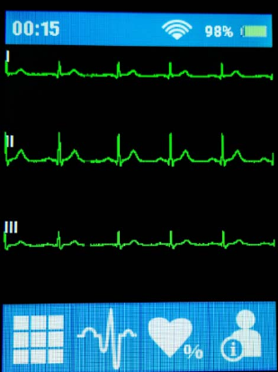
55of63
view and confirm good signal on all leads.
Patient Sessions
Sessions are assigned to a slot, managed, and ended at the MONITORING NODE.

56of63
15.
PRODUCT SPECIFICATIONS
General
Instrument Type Digital telemetry device with ECG.
Dimensions 3.5” x 2.8” x 1.1” (89 × 71 × 28 mm)
Input Channels Continuous 3 lead signal acquisition and transmission with 4-wire cables.
ECG Leads Transmitted 4-wire: I, II and III
Device Classification Type CF, battery operated
Special Functions ECG display, lead fail, battery notification
Defibrillator Protection IEC 60601-2-27
Function Keys Control button; touchscreen menu navigation
Display type High definition, antiglare Color TFT-LCD with LED backlight and capacitive
touch panel
Display size Display size: 77.3mm x 56.1mm
Display Active Area: 57.6mm x 43.2mm
Display Visual Area: 58.6mm x 44.2mm
Display resolution 240 x 320 pixels
Environmental
Temperature Operating temperature: +10° to +40° C (+50° to +104° F)
Storage temperature: -40° to +70° C (-40° to +158° F)
Humidity Operating humidity: 10% to 95% RH, non-condensing
Storage humidity: 10% to 95% RH, non-condensing
Altitude Operating & Storage: 62 kPa to 106 kPa
corresponds to an approx. altitude range of -260 m to 5000 m (-850 ft to 16404 ft)
Cooling Passive (no fan)
Weight < 200g (7.1 oz.) with rechargeable battery pack

57of63
PRODUCT SPECIFICATIONS
Power Requirements & Battery
Rechargeable Battery Type Rechargeable Lithium-ion battery pack
Rechargeable Battery Run-Time 32 hours (when configured with ECG only)
Battery Charging Time 4 hours
ECG Specifications
ECG With 4-wire ECG
Simultaneous Leads Available 4-wire: I, II and III
Acquisition Rate: 40,000 samples/s. for pacemaker detection, 500 samples/s for transmission
Resolution: .117µV originally, reduced to 2.5 µV for transmission
Dynamic Range ± 350mV
CMRR: According to applicable standards (IEC 60601-2-27)
Max. Auxiliary Patient
Current:
< 10 µA
Frequency Response: 0.05 to 150 Hz
Input Impedance: >2.5 MΩ at 10 Hz
Electrodes: Compatible with Ag/AgCl disposable electrodes
HR Report from the
MONITORING NODE
Less than one second. Heart rate is only available when the S2 is actively
communicating with the MONITORING NODE.
Recovery from Defibrillation
Discharge
Less than 5 seconds, compliant with IEC 60601-2-27.

58of63
Wireless Network Specifications
Wireless protocol 802.11 a/b/g/n 2.4 GHz or 5 GHz
Disable 802.11b support on WLAN infrastructure.
If 802.11b support is required, do not specify any 802.11b data rate as mandatory.
Frequency Range 2.400 GHz to 2.483 GHz; 5.15 GHz to 5.35 GHz, 5.725 GHz to 5.825 GHz
802.11a/g supported rates 6, 9, 12, 18, 24, 36, 48, 54 Mbps
802.11n supported rates MCS0 through MCS7
6.5, 13, 19.5, 26, 39, 52, 58.5, 65 Mbps
Transmit Power 15 dBm
Configure WLAN APs maximum transmitting power to 15 dBm
Channels 1, 6, 11 with 2.4GHz
36, 40, 44, 48, 149,153,157, 161 with 5GHz
Wireless security protocols WPA2-PSK-AES, passphrase
WMM / QoS Yes
SSID Requirements Dedicated SSID is required. Hidden SSID not supported.
SSID can be up to 24 ASCII characters long, per 802.11.
SSID prioritization and minimum bandwidth configuration on WLAN infrastructure is
recommended.
Period Session Timeout or similar policies should be disabled or excluded in the SSID
dedicated to the S2: these policies might cause data gaps of a few seconds whenever the
AP terminates the session.
IP address assignment Static or DHCP
IP protocols and ports UDP: one port per device, according to the system configuration (Base port number
30000). Actual ports will be communicated upon definition of the system
configuration;
ICMP
Maximum devices per Access
Point
16
Data Rate (payload) Outbound: < 80 kbps
Inbound: < 24 kbps
Minimum RSSI / SNR -70 dBm in the coverage area
Minimum SNR 20 dB in the coverage area
Target total channel occupancy < 50%

59of63
16.
TROUBLESHOOTING
The following table provides guidance for investigating issues that may occur during operation of the S2. Contact
Mortara Technical Support and Service by calling 1-888-MORTARA (US & Canada) or +1-414-354-1600
(Worldwide) or via e-mail at techsupport@mortara.com for further assistance.
Power and Battery
Symptom Possible Causes Suggested Resolution
The S2 is not working
and display does not
light up.
Internal system failure.
Power cycle the S2 with fresh batteries and try
again. If problems persist, stop using the S2 and
contact Mortara Technical Support.
Battery will not hold charge. Replace the battery according to instructions in
the General Care & Maintenance chapter.
Display and Touchscreen
Symptom Possible Causes Suggested Resolution
The touchscreen is not
working properly.
Touchscreen failure.
Power cycle the S2 and try again. If problems
persist, stop using the S2 and contact Mortara
Technical Support.
The display is not
working properly.
Display failure.
Power cycle the S2 and try again. If problems
persist, stop using the S2 and contact Mortara
Technical Support.
ECG Trace
Symptom Possible Causes Suggested Resolution
ECG signal is noisy.
Excessive patient movement. Confirm electrode site preparation; confirm correct
ECG positioning, move electrodes if needed.
Electrical noise from auxiliary
equipment.
Isolate the patient from auxiliary equipment, if
possible.
Bad electrode contact.
Check to make sure electrodes are still securely
attached to the patient, and reattach if necessary.
Remember the importance of good skin
preparation techniques.

60of63
TROUBLESHOOTING
Network Transmission
Symptom Possible Causes Suggested Resolution
1.
X symbol on
WLAN signal
indicator.
2.
"AP MAC: Not-
Associated" in the
WLAN diagnostic
screen.
3.
Invalid IP address if
configured for DHCP.
4.
Inability to ping in
WLAN diagnostic
screen.
Incorrect WLAN configuration
(e.g., SSID, Security protocol,
Passkey, Passkey type).
Check WLAN network settings; contact your
IT Network Administrator to correct issues.
WLAN infrastructure issues
(e.g. device placed on black
list).
Check WLAN network settings; contact your
IT Network Administrator to correct issues.
1.
Normal symbol on
WLAN signal
indicator.
2.
Network info
correctly populated
in WLAN
diagnostic screen.
3.
Invalid IP address if
configured for
DHCP.
4.
Inability to ping in
WLAN diagnostic
screen.
Incorrect LAN configuration
(Method, IP, Subnet,
Gateway).
Check LAN network settings; contact your IT
Network Administrator to correct issues.
LAN infrastructure issues (e.g.
DHCP server is not providing
an IP address).
Check LAN IPv4 network settings; contact your IT
Network Administrator to correct issues.

61of63
TROUBLESHOOTING
Symptom Possible Causes Suggested Resolution
Any of the following:
1.
Intermittent traces on
MONITORING
NODE,
2.
X or low signal symbol
on WLAN signal
indicator.
3.
Intermittent "AP MAC:
Not-Associated" in
WLAN diagnostic
screen, low signal,
high noise, low quality
indexes.
4.
Intermittent Valid IP
address if configured
for DHCP.
5.
Inconsistent Ping
results in WLAN
diagnostic screen.
Poor WLAN network
coverage.
Check IT Network Administrator to correct issues.

62of63
17.
REORDERING ACCESSORIES & CONSUMABLES
Use the following Mortara part numbers to obtain spare parts or to reorder accessories:
Power accessories
Description Part Numbers
LI-ION BATTERY PACK 4800-020
BATTERY CHARGER 4102-003
Mounts / holders
TIE-ON DISPOSABLE POUCH - BOX 100** 8485-029-51
ECG accessories
ECG LEAD SET 4 WIRE CLIP ENDS AHA GRAY 9293-059-80
ECG LEAD SET 4 WIRE CLIP ENDS IEC GRAY 9293-059-81
ECG LEAD SET 4 WIRE SNAP ENDS AHA GRAY 9293-059-82
ECG LEAD SET 4 WIRE SNAP ENDS IEC GRAY 9293-059-83
HOOKUP KIT MONITORING 10E SINGLE** 9294-009-50
ELECTRODES, 10/POUCH ** 9300-032-52
ELECTRODES, 300/CASE (10/pouch, 30 pouches/case) ** 9300-032-50
Other
S2 USER MANUAL 9515-210-50-CD
* Technical Service Installation Required.
** This item is intended for single patient use. Items warranted to be free of defects in workmanship and materials
for a period of 90 days or first use, whichever comes first.
To order additional supplies, contact your Mortara Customer Service Representative.

63of63
18.
APPLIED STANDARDS
IEC 60601-1:2005/A1:2012-Ed.3.1, Medical electrical equipment – Part 1: General requirements for basic
safety and essential performance
European Union: CENELEC EN60601-1:2006 Medical Electrical Equipment Part 1: General Requirements for
Basic Safety and Essential Performance.
USA: AAMI ES60601-1:2005 Medical electrical equipment Part 1: General Requirements for Basic Safety and
Essential Performance.
Canada: CSA C22.2#60601-1:2008 Ed:3 Medical Electrical Equipment – Part 1: General requirements for basic
Safety and essential performance.
IEC 60601-1-2:2014 Medical Electrical Equipment – Part 1-2: General requirements for safety – Collateral
Standard: Electromagnetic Compatibility.
IEC 60601-2-27:2011-08 Edition 3.0, Medical Electrical Equipment. Part 2-27: Particular requirements for the
basic safety and essential performance of electrocardiographic monitoring equipment.
(Notes: Applies to 3/5-wire and 10-wire acquisition modules; when used in conjunction with a MONITORING
NODE.)
ETSI EN 301 489-1:2017-02 v2.1.1, Electromagnetic compatibility and Radio Spectrum Matters, Part 1: Common
technical requirements.
ETSI EN 301 489-17:2017-02 v3.1.1, Electromagnetic compatibility and Radio Spectrum Matters, Part 17: Specific
conditions for Broadband Data Transmissions Systems.
ETSI EN 300 328:2016-11 v2.1.1, Electromagnetic compatibility and Radio Spectrum Matters, Wideband
transmission systems; Data transmission equipment operating in the 2.4 GHz ISM band and using wide band
modulation techniques.
ISO 10993-1:1997-12-15, 2nd Edition, ISO 10993-5:2009/(R)2014, 2nd Edition, ISO 10993-10:2002-09-01, 2nd
Edition ISO 10993-1:2009/Cor.1:2010, Biological evaluation of medical devices – Part 1: Evaluation and testing
within a risk management process
AAMI/ANSI/ISO 10993-5:2009/(R)2014, Biological evaluation of medical devices – Part 5: Tests for in vitro
cytotoxicity.
ISO 10993-10:2010, Biological evaluation of medical devices – Part 10: Tests for irritation and skin
sensitization
Title 47 CFR Part 15, US Federal Communications Commission Part 15 Rules for Intentional Radiators.
2014/53/EU: European Council Directive on the harmonization of laws relating to radio equipment.. (RED
Directive)
2002/96/EC:2003, Waste Electrical and Electronic Equipment (WEEE).
2002/95/EC:2003, Restriction of the use of Certain Hazardous Substances in Electrical and Electronic
Equipment (RoHS).
IEC 62366:2014-Ed.1.1, Medical devices – Application of usability engineering to medical devices
93/42/EEC: Council Directive of 14 June 1993 concerning medical devices. (Medical Device Directive)