Inventek Systems RL78 2.4 GHz BTLE wireless module User Manual
Inventek Systems 2.4 GHz BTLE wireless module
UserManual.wiki
>
Inventek Systems
>
RL78 User Manual
User Manual
Navigation menu
Upload a User Manual
Namespaces
Wiki Guide
HTML
PDF
Info
Views
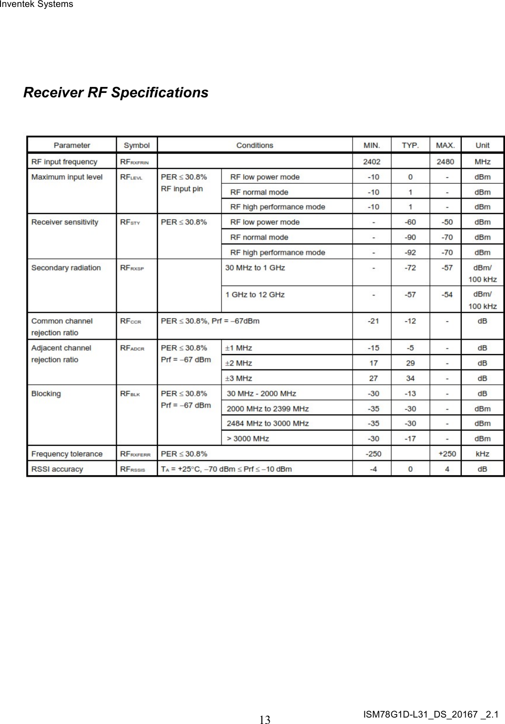
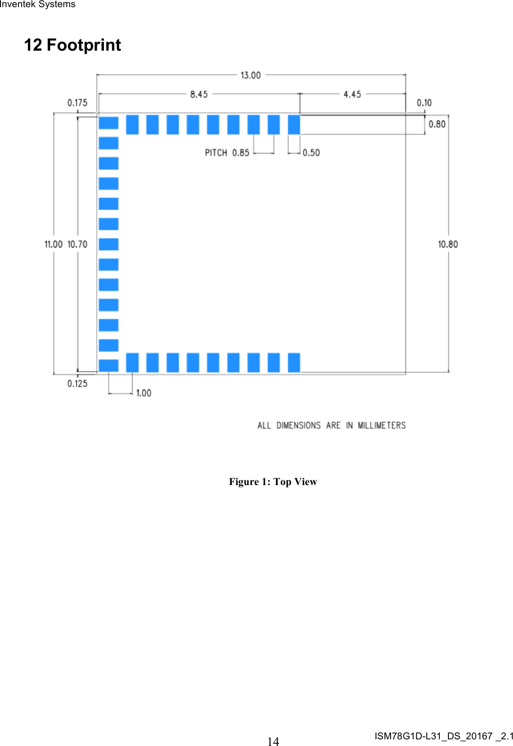
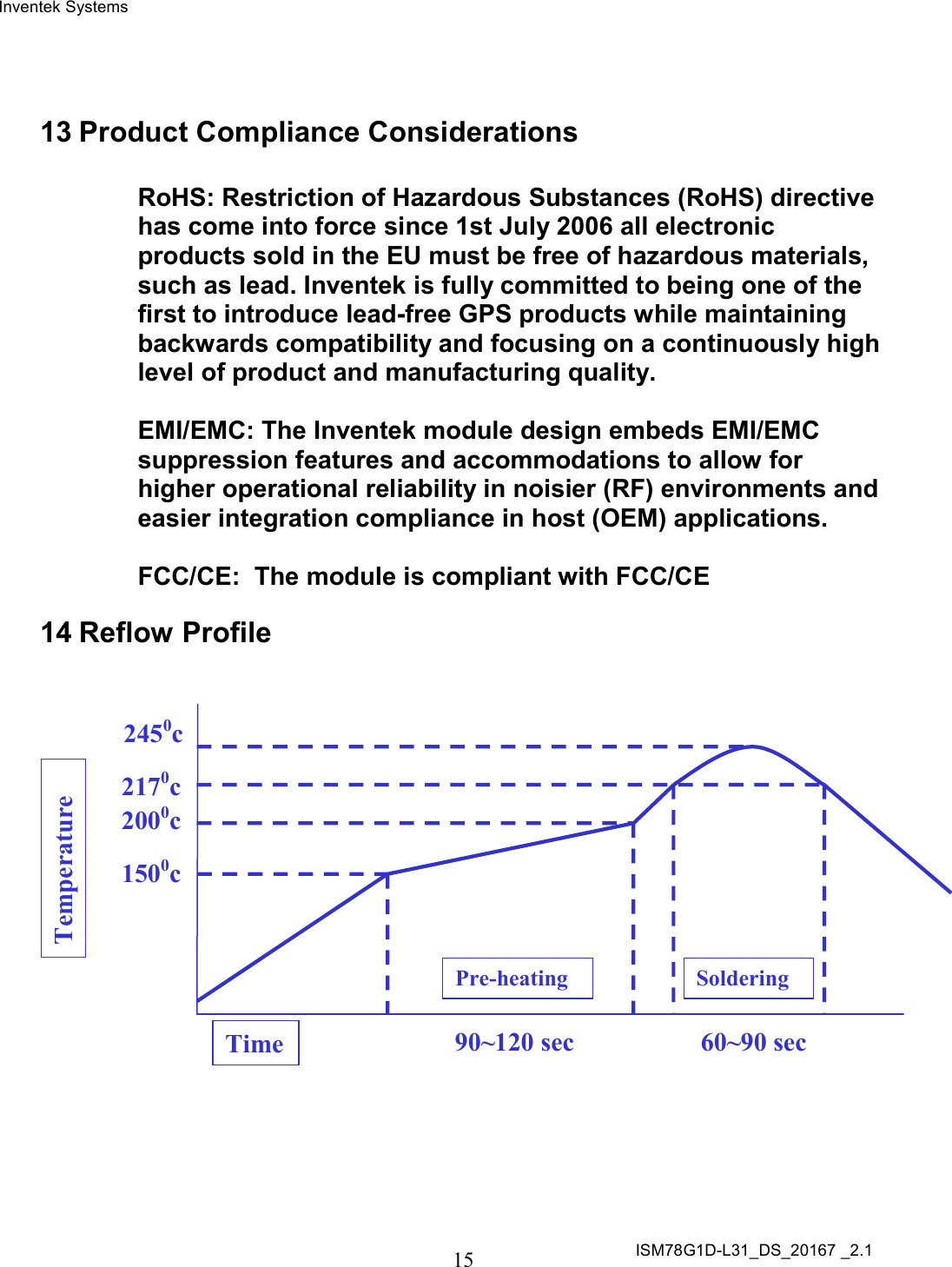
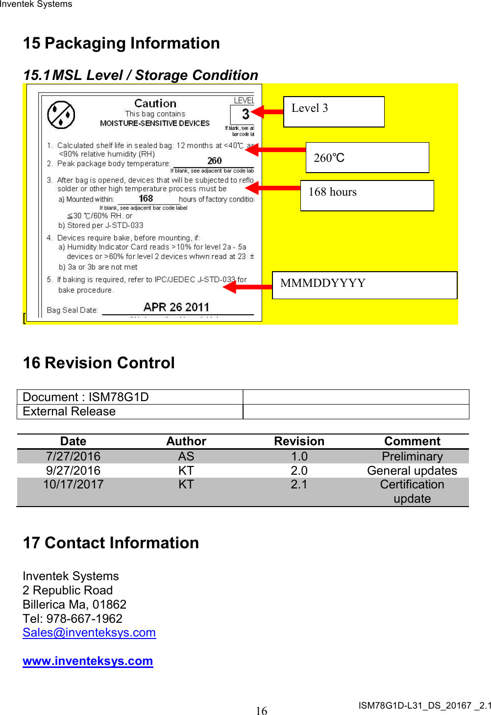
User Manual
Discussion / Help
Navigation