Inventek Systems RL78 2.4 GHz BTLE wireless module User Manual
Inventek Systems 2.4 GHz BTLE wireless module
User Manual
Bluetooth Low Energy SIP Module
OEM/Integrators Installation Manual
Inventek
Systems
ISMRL78G1D
Embedded
Bluetooth Low Energy SIP Module
OEM/Integrators Installation Manual
OEM/Integrators Installation Manual
Inventek Systems
ISM78G1D-L31_DS_20167 _2.1
2
Table of Contents
1 General Description ............................................................................................................ 3
2 Part Number Detail Description.......................................................................................... 4
2.1 Ordering Information ...................................................................................................... 4
3 General Features ................................................................................................................. 4
3.1 Limitations ...................................................................................................................... 5
3.2 Regulatory Compliance .................................................................................................. 5
4 Complementary Documents................................................................................................ 7
4.1 Inventek Systems ............................................................................................................ 7
5 Specifications ...................................................................................................................... 8
5.1 Block Diagram ................................................................................................................ 8
6 Environmental Specifications ............................................................................................. 8
7 Hardware Electrical Specifications ..................................................................................... 8
7.1 Absolute Maximum Ratings ........................................................................................... 8
7.2 Recommended Operating Ratings .................................................................................. 8
7.3 ADC Specifications ........................................................................................................ 8
Notes 1. Current flowing to VDD. .............................................................................................. 9
8 Power Consumption ............................................................................................................ 9
8.1.1 Estimated Power Consumption ................................................................................... 9
9 Module Pin Out ................................................................................................................. 10
9.1 Detailed Pin Description: .................................................................................................... 11
10 AC Characteristics ............................................................................................................ 12
11 Bluetooth Low energy Specifications ............................................................................... 12
11.1 Transmitter RF Specifications ...................................................................................... 12
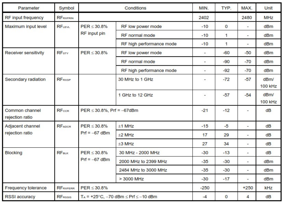
Receiver RF Specifications ....................................................................................................... 13
12 Footprint ............................................................................................................................ 14
13 Product Compliance Considerations ................................................................................. 15
14 Reflow Profile ................................................................................................................... 15
15 Packaging Information ...................................................................................................... 16
15.1 MSL Level / Storage Condition .................................................................................... 16
16 Revision Control ............................................................................................................... 16
17 Contact Information .......................................................................................................... 16

Inventek Systems
ISM78G1D-L31_DS_20167 _2.1
3
1 General Description
The Inventek ISMRL78G1D module is an embedded wireless Bluetooth low energy
(BLE) connectivity device, based on the RenesasRL78/G1Dmicrocomputer
incorporating the RL78 CPU core and low power consumption RF transceiversupporting
the Bluetooth ver.4.1 (Low Energy Single mode) specifications.
The Inventek ISMRL78G1D offers a RL78 CPU core is a3-stage pipelineCISC
architecture with an integrated BLE radio, on-board chip antenna, and256KB ROM.
The module provides a number of features and standard peripheral interfaces (see
“Summaryof Key Features” below), enabling connection to an embedded design. The
low cost, small foot print,11mmx13mm 31-Pin LGA package and ease of design-in
make it ideal for a range of embedded applications.
Note: This module is limited to OEM installation ONLY.
Summary of Key Features:
Bluetooth low energy (BLE)-compliant
CISC architecture with 3-stage pipeline
o Minimum instruction execution time: Can be changed from high speed
(0.03125 us: @ 32 MHz operation with high speed On-chip oscillator) to
ultra-low speed (30.5 us: @ 32.768 kHz operation with subsystem clock)
o Address space: 1 MB
o General-purpose registers: (8-bit register × 8) × 4 banks
On-chip RF transceiver
o Bluetooth v4.1 Specification (Low Energy Single mode)
o 2.4 GHz ISM band, GFSK modulation, TDMA/TDD frequency hopping
(including AES encryption circuit)
o Adaptivity, exclusively for use in operation as a slave device
Code flash memory
o Code flash memory: 256KB
o Block size: 1KB
o Prohibition of block erase and rewriting (security function)
o On-chip debug function
o Self-programming (with boot swap function/flash shield window function)
Data flash memory
o Data flash memory: 8KB
o Back ground operation (BGO): Instructions can be executed from the
program memory while rewriting the data flash memory.
o Number of rewrites: 1,000,000 times (TYP.)
o Voltage of rewrites: VDD = 1.8 to 3.6 V

Inventek Systems
ISM78G1D-L31_DS_20167 _2.1
4
Typical Applications:
The module has been designed to provide low power, low cost, and robust
communications for applications operating in the globally available 2.4GHz unlicensed
industrial, scientific, and medical (ISM) band. The following application profiles are
supported in ROM:
o Battery Status
o Blood Pressure Monitor
o Find Me
o Heart Rate Monitor
o Proximity
o Thermometer
o Weight Scale
o Time
Additional profiles that can be supported from RAM include:
o Blood Glucose Monitor
o Temperature Alarm
o Location
2 Part Number Detail Description
2.1 Ordering Information
Part Number
Description
Ordering
ISM78G1D-L31 Bluetooth LE Module
Tube
ISM78G1D-L31-TR Bluetooth LE Module
Tape & Reel
3 General Features
o Based on the Renesas RL78/G1D Bluetooth Low Energy 4.1 Baseband/Radio
device.
o Integrates Bluetooth embedded stack, and fully qualified application profiles in
ROM
o Power-saving mode allows the design of low-power applications.
o Lead Free Design which is compliant with ROHS requirements.
o FCC/CE Compliance Certified ( In process )

Inventek Systems
3.1 Limitations
Inventek Systems products are not authorized for use in safety
(such as life support) where a failure of the Inventek Systems product would
reasonably be expected to cause severe personal injury or death.
The OEM integrator is respo
instructions to remove or install module.
The module is limited to installation in mobile or fixed application ONLY. A separate
approval is required for all other operating configuration including porta
configuration with respect to FCC Part 2.1093 and different antenna configurations.
The OEM/Integrator can expect to receive guidance from the grantee to ensure
compliance with Part 15 Subpart B requirements provide the module is being used
within th
e grant restrictions and instruction detailed within this manual. In the event
that these conditions cannot be met (for example certain host configurations or
collocation configurations may results in deviations from Grantee’s recommend
practice) then the
FCC authorization may no longer be consider valid and the FCC
ID cannot be used on the final host product. In these circumstances, the OEM
Integrator will be responsible for reevaluating the end product (including the
transmitter) and obtaining a new sep
intended only for OEM Integrators under and under the following conditions: As long
as the conditions in this manual are met include RF Exposure requirements and
Antenna requirements, further transmitter testing wil
OEM Integrator is responsible for testing their end product for any additional
compliance requirements such as compliance with Part 15 Subpart B.
3.2
Regulatory Compliance
FCC ID: O7P-RL78
IC: 10147A-RL78
There are
specific regulatory requirements imposed by regulatory authorities around
the world on radio devices.
engage with an accredited test lab to determine the overall system level regulatory
requirements. Custo
mers may be able to leverage
Please discuss the process with your test lab, such as FCC ID transfers.
can provide authorizations as needed
ISM78G1D-
L31_DS_20167 _2.1
5
Inventek Systems products are not authorized for use in safety
-
critical applications
(such as life support) where a failure of the Inventek Systems product would
reasonably be expected to cause severe personal injury or death.
The OEM integrator is respo
nsible for ensuring that the end-
user has no manual
instructions to remove or install module.
The module is limited to installation in mobile or fixed application ONLY. A separate
approval is required for all other operating configuration including porta
configuration with respect to FCC Part 2.1093 and different antenna configurations.
The OEM/Integrator can expect to receive guidance from the grantee to ensure
compliance with Part 15 Subpart B requirements provide the module is being used
e grant restrictions and instruction detailed within this manual. In the event
that these conditions cannot be met (for example certain host configurations or
collocation configurations may results in deviations from Grantee’s recommend
FCC authorization may no longer be consider valid and the FCC
ID cannot be used on the final host product. In these circumstances, the OEM
Integrator will be responsible for reevaluating the end product (including the
transmitter) and obtaining a new sep
arate FCC authorization. This device is
intended only for OEM Integrators under and under the following conditions: As long
as the conditions in this manual are met include RF Exposure requirements and
Antenna requirements, further transmitter testing wil
l not be required. However the
OEM Integrator is responsible for testing their end product for any additional
compliance requirements such as compliance with Part 15 Subpart B.
Regulatory Compliance
specific regulatory requirements imposed by regulatory authorities around
the world on radio devices.
Customers using Renesas
SIP modules are advised to
engage with an accredited test lab to determine the overall system level regulatory
mers may be able to leverage
Renesas
' regulatory test reports.
Please discuss the process with your test lab, such as FCC ID transfers.
can provide authorizations as needed
.
L31_DS_20167 _2.1
critical applications
(such as life support) where a failure of the Inventek Systems product would
user has no manual
The module is limited to installation in mobile or fixed application ONLY. A separate
approval is required for all other operating configuration including porta
ble
configuration with respect to FCC Part 2.1093 and different antenna configurations.
The OEM/Integrator can expect to receive guidance from the grantee to ensure
compliance with Part 15 Subpart B requirements provide the module is being used
e grant restrictions and instruction detailed within this manual. In the event
that these conditions cannot be met (for example certain host configurations or
collocation configurations may results in deviations from Grantee’s recommend
FCC authorization may no longer be consider valid and the FCC
ID cannot be used on the final host product. In these circumstances, the OEM
Integrator will be responsible for reevaluating the end product (including the
arate FCC authorization. This device is
intended only for OEM Integrators under and under the following conditions: As long
as the conditions in this manual are met include RF Exposure requirements and
l not be required. However the
OEM Integrator is responsible for testing their end product for any additional
compliance requirements such as compliance with Part 15 Subpart B.
specific regulatory requirements imposed by regulatory authorities around
SIP modules are advised to
engage with an accredited test lab to determine the overall system level regulatory
' regulatory test reports.
Please discuss the process with your test lab, such as FCC ID transfers.
Renesas

Inventek Systems
ISM78G1D-L31_DS_20167 _2.1
6
When this transmitter is installed in a host device, you must place a permanent label,
visible on the outside of the device which includes the following information:
Contains: FCC ID: O7P-RL78
Contains: IC: 10147A-RL78
This device complies with part 15 of the fcc rules. operation is subject to the
following two conditions.(1) this device may not cause harmful interference, and (2)
this device must accept any interference received, including interference that may
cause undesired operation.
Warning: Changes or modifications not expressly approved by the party responsible
could void the user’s authority to operate the product.
NOTE: This equipment has been tested and found to comply with the limits for a
Class B digital device, pursuant to part 15 of the FCC Rules. These limits are
designed to provide reasonable protection against harmful interference in a
residential installation. This equipment generates, uses and can radiate radio
frequency energy and, if not installed and used in accordance with the instructions,
may cause harmful interference to radio communications. However, there is no
guarantee that interference will not occur in a particular installation. If this equipment
does cause harmful interference to radio or television reception, which can be
determined by turning the equipment off and on, the user is encouraged to try to
correct the interference by one or more of the following measures: —Reorient or
relocate the receiving antenna. —Increase the separation between the equipment
and receiver. —Connect the equipment into an outlet on a circuit different from that
to which the receiver is connected. —Consult the dealer or an experienced radio/ TV
technician for help.
This equipment uses the following Antennas and may not be used with other
antenna types or with antennas of higher gain:
Mfg.: Inventek Systems
Type: Etched Antenna
Gain:0 dBi
This equipment complies with FCC Radiation Exposure limits and should be installed
and operated with a minimum distance of 20cm between the radiator and any part of the
human body.
ISED (Canada)
Required Notices to the User

Inventek Systems
ISM78G1D-L31_DS_20167 _2.1
7
This device complies with Industry Canada licence-exempt RSS standard(s).
Operation is subject to the following two conditions: (1) this device may not cause
interference, and (2) this device must accept any interference, including interference
that may cause undesired operation of the device.
Le présent appareil est conforme aux CNR d'Industrie Canada applicables aux
appareils radio exempts de licence. L'exploitation est autorisée aux deux conditions
suivantes : (1) l'appareil ne doit pas produire de brouillage, et (2) l'utilisateur de
l'appareil doit accepter tout brouillage radioélectrique subi, même si le brouillage est
susceptible d'en compromettre le fonctionnement.
This radio transmitter, IC: 10147A-RL78, has been approved by Industry Canada to
operate with the antenna types listed below with the maximum permissible gain and
required antenna impedance for each antenna type indicated. Antenna types not
included in this list, having a gain greater than the maximum gain indicated for that type,
are strictly prohibited for use with this device.
Type:2.4 GHz chip antenna
Gain:-1.5 dBi
Le présent émetteur radio, IC: 10147A-RL78 a été approuvé par Industrie Canada pour
fonctionner avec les types d'antenne énumérés ci-dessous et ayant un gain admissible
maximal et l'impédance requise pour chaque type d'antenne. Les types d'antenne non
inclus dans cette liste, ou dont le gain est supérieur au gain maximal indiqué, sont
strictement interdits pour l'exploitation de l'émetteur.
Type:2.4 GHz chip antenna
Gain:-1.5 dBi
This equipment complies with the ICES RF radiation exposure limits set forth for an
uncontrolled environment. This equipment should be installed and operated with a
minimum distance of 20cm between the radiator and any part of the human body.
Cet équipement est conforme aux limites d'exposition aux radiations ICES définies pour
un environnement non contrôlé . Cet équipement doit être installé et utilisé à une
distance minimale de 20 cm entre le radiateur et une partie de votre corps.
4 Complementary Documents
4.1 Inventek Systems
RL78/G1D Renesas Data Sheet
o P/N (R5F11AGJDNB#40)
ISM78G1D-L31 Product Brief
Inventek Systems
ISM78G1D-L31_DS_20167 _2.1
8
ISM78G1D-EVB Quick Start Guide
Renesas Tools and Design Environment
FCC Test Report
5 Specifications
5.1 Block Diagram
Available upon request
6 Environmental Specifications
Item
Description
Operating Temperature Range
-40 deg. C to +80 deg. C
Storage Temperature Range -65 deg. C to +150 deg. C
Humidity 95% max non-condensing
7 Hardware Electrical Specifications
7.1 Absolute Maximum Ratings
Symbol
Description
Min
Max
Unit
Supply Power Input Supply Voltage
1.8 3.6 V
Voltage Ripple
0 +/-2%
VDD, VDD_RF
1.8 3.6 V
7.2 Recommended Operating Ratings
Symbol
Min
Typ
Max
Unit
VDD - 3.3 - V
VDD_RF
- 3.3 - V
7.3 ADC Specifications
Parameter
Symbol
Conditions
Min
Typ
Max
Unit
A/D converter
operating current
IADC
1, 2
When conversion at
maximum speed
AVREFP = VDD = 3.0 V
0.5 0.7 mA

Inventek Systems
ISM78G1D-L31_DS_20167 _2.1
9
Notes 1. Current flowing to VDD.
Notes 2.Current flowing only to the A/D converter. The current value of MCU is the sum of IDD1 or IDD2
and IADC when theA/D converter operates in an operation mode or the HALT mode.
8 Power Consumption
The Power Management Unit (PMU) provides power management features that can be
invoked by software through power management registers or packet-handling in the
baseband core.
There are several Ultra-low power consumption technology operations:
MCU part
o Standby function HALT mode
o STOP mode
o SNOOZE mode
RF part
o Standby function POWER_DOWN mode
o RESET_RF mode
o STANDBY_RF mode
o IDLE_RF mode,
o DEEP_SLEEP mode, SLEEP_RF mode
RF transmission
o (RF normal mode): 4.3 mA (TYP.) (3.0 V/MCU part: STOP mode)
o (RF Low power mode): 2.6 mA (TYP.) (3.0 V/MCU part: STOP mode)
RF reception
o (RF normal mode): 3.5 mA (TYP.) (3.0 V/MCU part: STOP mode)
o (RF Low power mode): 3.3 mA (TYP.) (3.0 V/MCU part: STOP mode)
RF sleep
o (POWER_DOWN mode) operation: 0.10 uA (TYP.) (3.0 V/MCU part: STOP
mode)
8.1.1 Estimated Power Consumption
Operational
Mode
Description
Typ.
Max.
Unit
Receive Receiver and baseband are both operating,
100% — ON
3.5 mA
Transmit Transmitter and baseband are both operating 4.3 mA
Sleep Internal LPO is in use 0.10
- uA
Inventek Systems
ISM78G1D-L31_DS_20167 _2.1
10
9 Module Pin Out
CONFIDENTIAL. CONTACT MANUFACTURER FOR DETAILS.

Inventek Systems
ISM78G1D-L31_DS_20167 _2.1
11
9.1 Detailed Pin Description:
Pin # Pin Name Type
Description
1 VDD RF I VDD
2 GND I Ground
3 P30,XTAL1_RF I/O
Crystal oscillator (RF clock)
4 P16/TI01/TO01/INTP5 I/O
5 P15/SCK20/SCL20/(TI02)/(TO02) I/O
6 P14/SI20/SDA20/(SCLA0)/(TI03)/(TO03) I/O
7 P13/SO20/(SDAA0)/(TI04)/(TO04 I/O
0 P12/SO00/TxD0/TOOLTxD/(TI05)/(TO05) I/O
TX
9 P11/SI00/RxD0/TOOLRxD/SDA00/(TI06)/(TO06)
I/O
RX
10 P10/SCK00/SCL00/(TI07)/(TO07) I/O
11 P147/ANI18 I/O
12 P23/ANI3 I/O
13 P22/ANI2 I/O
14 P21/ANI1/AVREFM I/O
15 P20/ANI0/AVREFP I/O
16 P03/ANI16/RxD1 I/O
17 P02/ANI17/TxD1 I/O
18 P01/TO00 I/O
19 P00/TI00 I/O
20 VDD I VDD
21 nReset I
22 Tool0 I/O
Data I/O Flash Programmer
23 GND I Ground
24 P120/ANI19 I/O
25 P121/X1 I
26 P137/INTP0 I
27 P60/SCLA0 I/O
28 P61/SDDA0 I/O
29 GPIO1/TXSELL_RF I/O
30 GPIO0/TXSELH_RF I/O
31 GND I Ground

Inventek Systems
ISM78G1D-L31_DS_20167 _2.1
12
10 AC Characteristics
Items
Symb
Conditions
MIN.
TYP.
MAX.
Unit
RESETlow-levelwidth
tRSL
RESET
10 us
11 Bluetooth Low energy Specifications
On-Chip RF Transceiver
Bluetooth v4.1 Spec. (Low Energy, Single mode)
2.4 GHz ISM Band, GFSK modulation, TDMA/TDDFrequency
Hopping (included AES encryption circuit)
Adaptivity, exclusively for use in operation as aslave device
Single ended RF interface
11.1 Transmitter RF Specifications
The module requires a keep out area for the antenna section outside the metal can. Do
not put any metal directly below or above the antenna section and as this will reduce
antenna performance.
VDD=VDD_RF=3.3V, 25o C
Frequency 2440MHz
RF transmitter active: 4.3 mA (TYP.)
Parameter
Symbol
Conditions
Min
Typ
Max
Unit
Frequency CF 2402 2480 MHZ
Data Rate 1 Mbps
Max
transmitted
output power
RF Power @ RF output
pin
-3 0 2.5 dBm
Transmit
Output Settings
0 0
Spurious
radiation
RF
TXSP
30-88MHz -76 dBm
88-216MHz -76 dBm
216-960 MHz -76 dBm
960-1000
MHz
-74 dBm
1-12.7 GHz -74 dBm
Harmonics RF
TXHC1
2
nd
Harmonic -52 dBm
RF
TXCH2
3
rd
Harmonic -51 dBm
Inventek Systems
ISM78G1D-L31_DS_20167 _2.1
13
Receiver RF Specifications
Inventek Systems
ISM78G1D-L31_DS_20167 _2.1
14
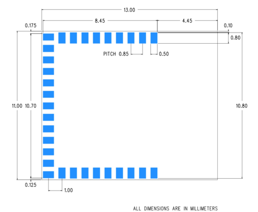
12 Footprint
Figure 1: Top View
Inventek Systems
ISM78G1D-L31_DS_20167 _2.1
15
13 Product Compliance Considerations
RoHS: Restriction of Hazardous Substances (RoHS) directive
has come into force since 1st July 2006 all electronic
products sold in the EU must be free of hazardous materials,
such as lead. Inventek is fully committed to being one of the
first to introduce lead-free GPS products while maintaining
backwards compatibility and focusing on a continuously high
level of product and manufacturing quality.
EMI/EMC: The Inventek module design embeds EMI/EMC
suppression features and accommodations to allow for
higher operational reliability in noisier (RF) environments and
easier integration compliance in host (OEM) applications.
FCC/CE: The module is compliant with FCC/CE
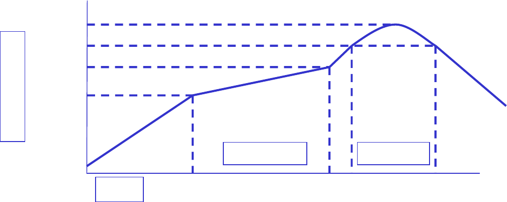
14 Reflow Profile
200
0
c
217
0
c
245
0
c
150
0
c
Pre-heating Soldering
90~120 sec 60~90 sec
Temperature
Time
Inventek Systems
ISM78G1D-L31_DS_20167 _2.1
16
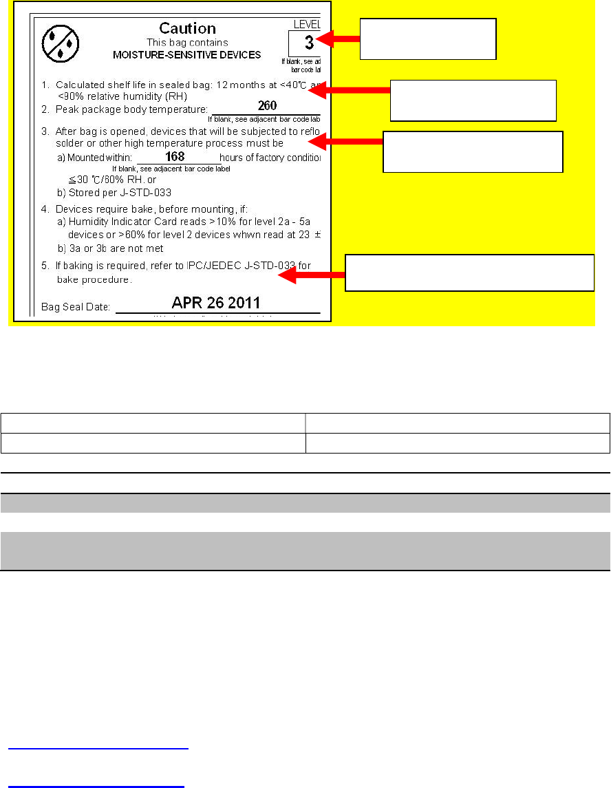
15 Packaging Information
15.1 MSL Level / Storage Condition
[
16 Revision Control
Document : ISM78G1D
External Release
Date
Author
Revision
Comment
7/27/2016 AS 1.0 Preliminary
9/27/2016 KT 2.0 General updates
10/17/2017 KT 2.1 Certification
update
17 Contact Information
Inventek Systems
2 Republic Road
Billerica Ma, 01862
Tel: 978-667-1962
Sales@inventeksys.com
www.inventeksys.com
Level 3
260℃
168 hours
MMMDDYYYY
Inventek Systems
ISM78G1D-L31_DS_20167 _2.1
17
Inventek Systems reserves the right to make changes without further notice to any products or data herein to improve reliability,
function, or design. The information contained within is believed to be accurate and reliable. However Inventek Systems does not
assume any liability arising out of the application or use of this information, nor the application or use of any product or circuit
described herein, neither does it convey any license under its patent rights nor the rights of others.