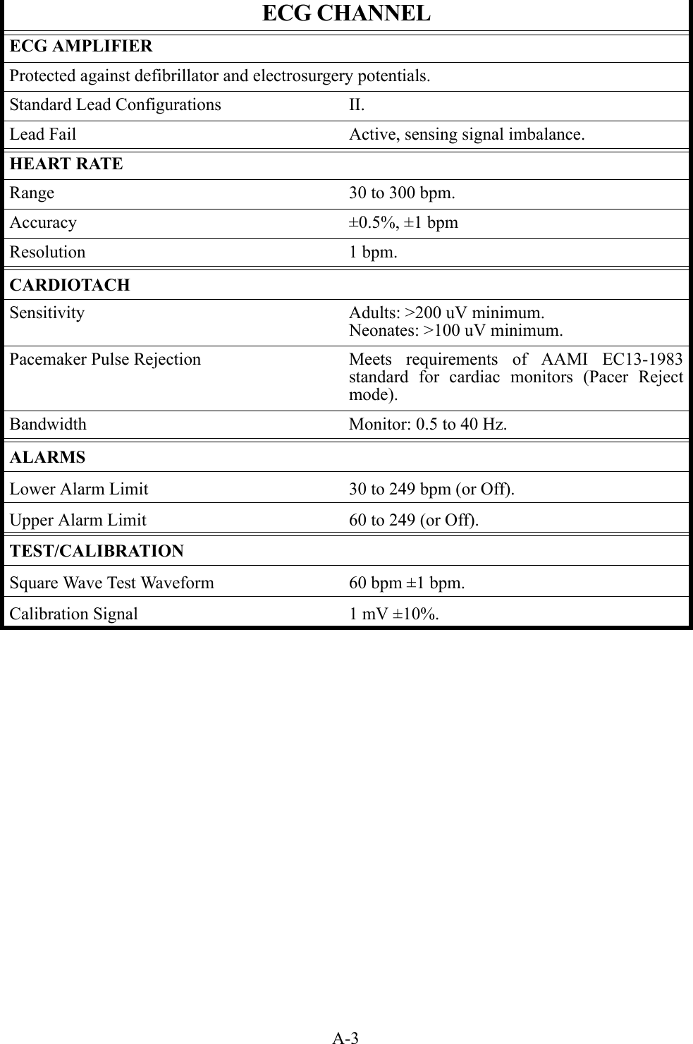
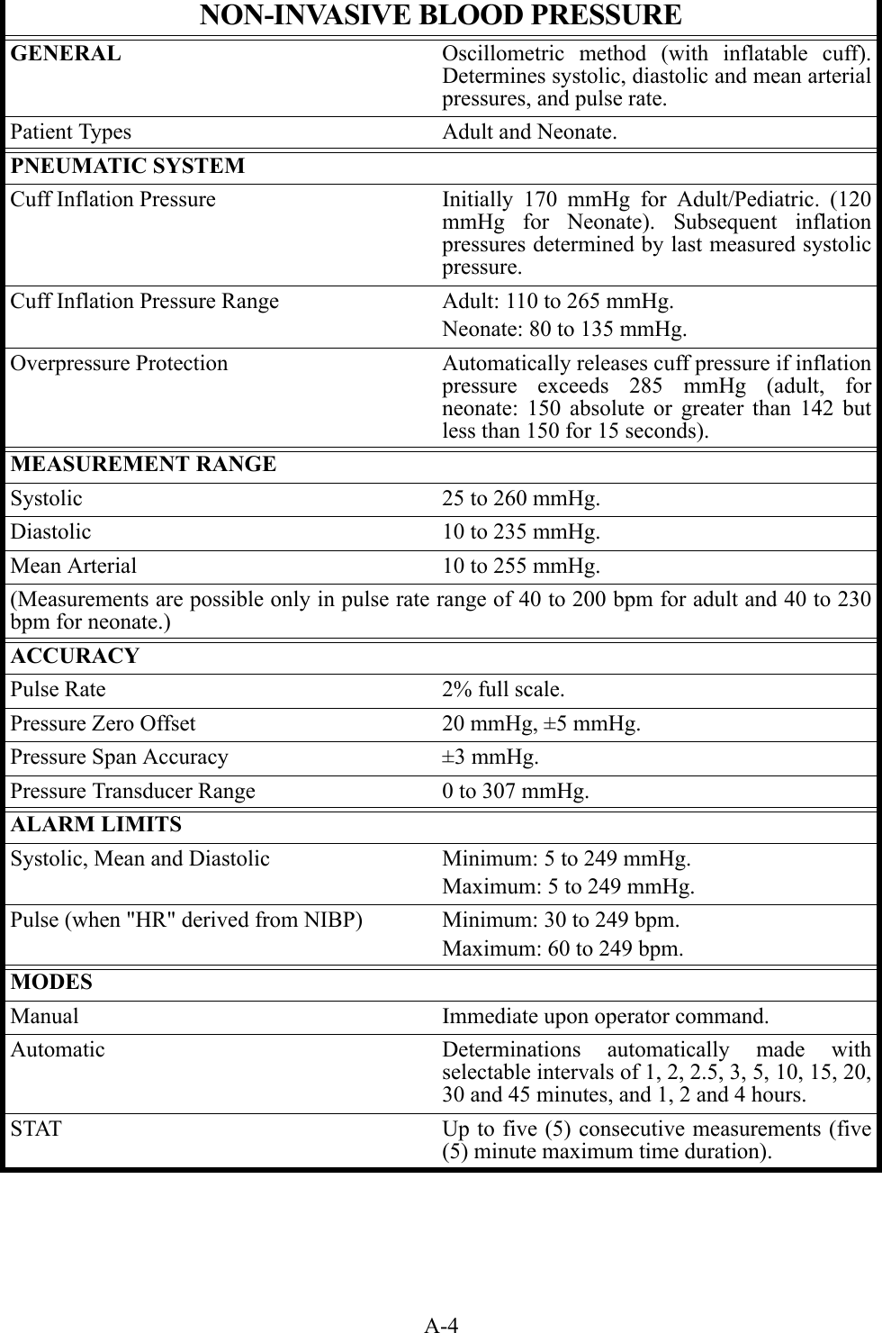
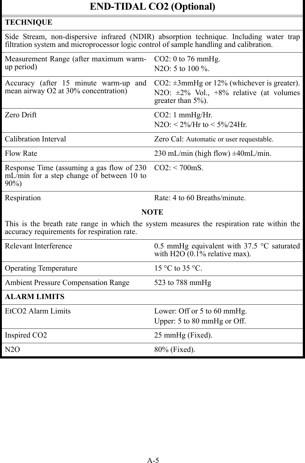
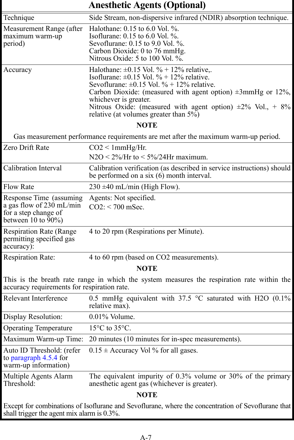
Invivo DR3160BAS Base Dual Transmitter User Manual 9567
Invivo Corporation Base Dual Transmitter 9567
UserManual.wiki
>
Invivo
>
DR3160BAS User Manual
users manual
Navigation menu
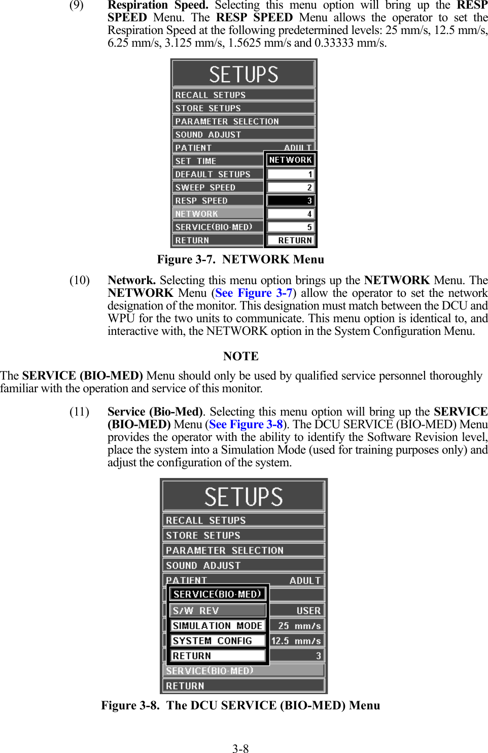
Upload a User Manual
Namespaces
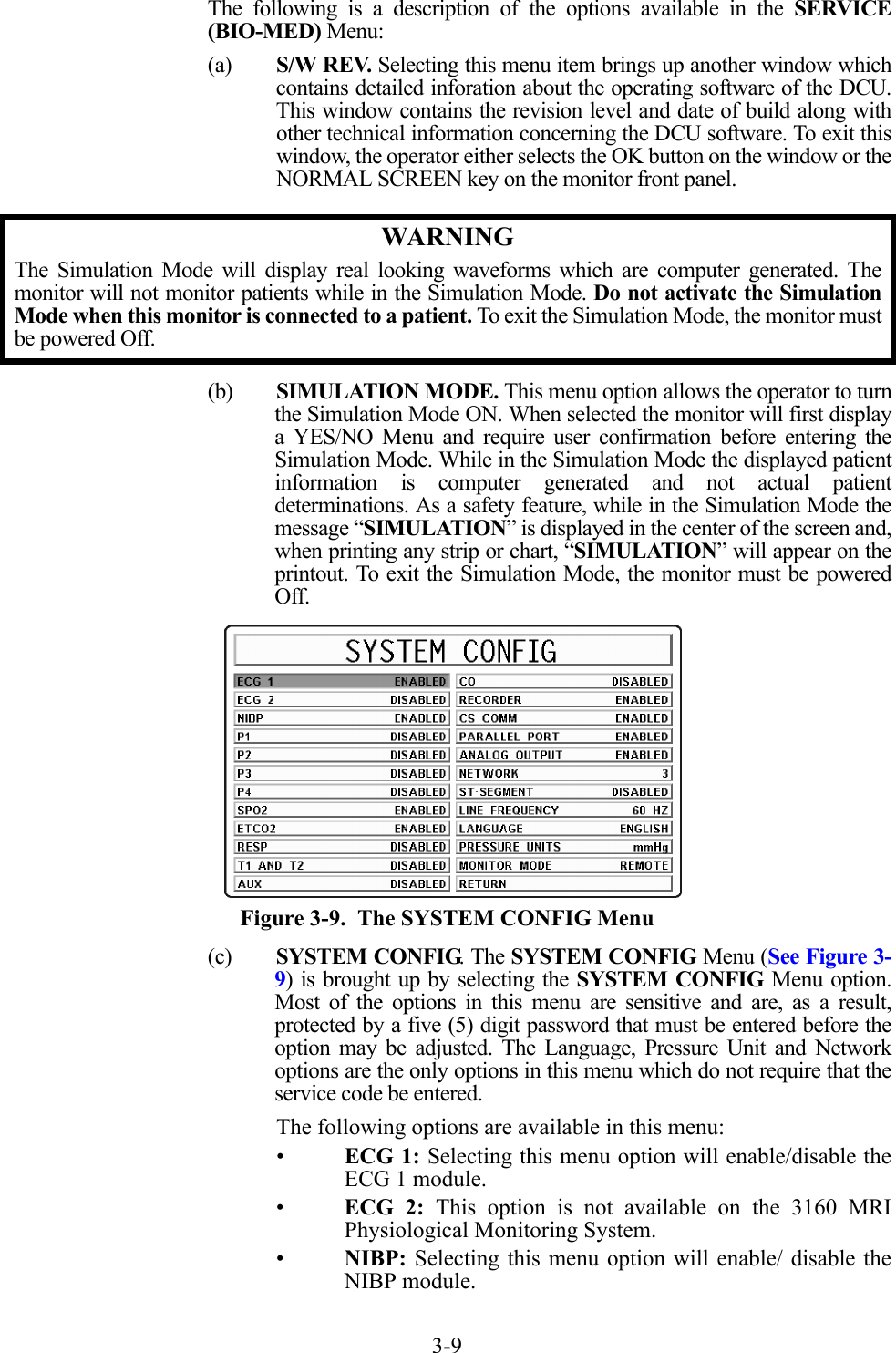
Wiki Guide
HTML
PDF
Info
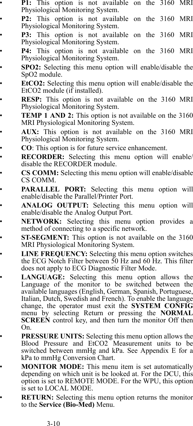
Views
User Manual
Discussion / Help
Navigation


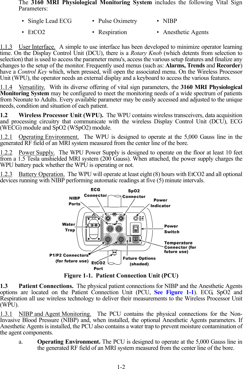
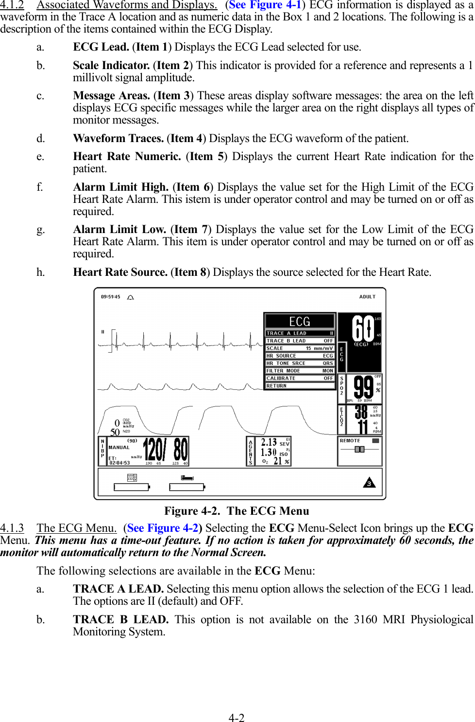
![viiPrecautionsElectrical SafetyTo avoid an electrical hazard, never immerse the unit in any fluid or attempt to clean it with liquidcleaning agents. Always disconnect monitor from AC Main Power before performing cleaning ormaintenance.If monitor becomes accidentally wet during use, discontinue operation of the monitor until allaffected components have been cleaned and permitted to dry completely. Contact your localInvivo representative if additional information is required.Shock hazard exists if operated without chassis cover. Refer servicing to qualified servicepersonnel only.For continued protection against fire hazard, replace fuses with same type and rating only.Connect the monitor only to a three-wire, grounded, hospital-grade receptacle. The three-conductor plug must be inserted into a properly wired three-wire receptacle; if a three-wirereceptacle is not available, a qualified electrician must install one in accordance with thegoverning electrical code.Do not under any circumstances remove the grounding conductor from the power plug.Avoid use of electrical power extension cords. Electrical power extension cords may create asafety hazard by compromising the grounding integrity of the monitor.None of the monitor interconnection ports on the rear of the monitor (e.g. Communication Ports,Auxiliary Input/Output port [AUX I/O], ECG Sync Input [ECG SYNC IN], Keyboard or VideoInput) are intended for direct patient connection. An electric shock hazard can exist if the patientis electrically connected to any of these connections.This monitor and its listed accessories may be safely powered by the voltages 110-120/220-240VAC having a frequency of 50 or 60 Hz.If the integrity of the earth ground conductor of the AC mains power cable is in doubt, operate themonitor on internal battery power until proper earth ground connection is confirmed.Patient SafetyConstant attention by a qualified individual is needed whenever a patient is under anesthesia orconnected to a ventilator. Some equipment malfunctions may occur in spite of equipment ormonitor alarms.Always test sampling line adapter for a tight connection and proper operation before attaching toa patient.As with all medical equipment, carefully route patient cabling to reduce the possibility of patiententanglement or strangulation.Occupational SafetyConnect the sample gas outlet on the monitor's rear panel to a scavenging system to preventpollution of room air.Handle the Patient Sampling Line and its contents as you would any body fluid. Infectious hazardmay be present.MRI Use PrecautionsCertain components of this device will be affected by the magnetic and radio frequency fields presentin your MRI System. Confer with your MRI physicist and/or Radiology staff to identify the properplacement and use areas for the monitor and its accessories, as defined on the monitor or accessorylabeling. Failure to properly place the monitor and its accessories in the Magnet Room will result inmonitor failure, and possible patient or user injury. Always position the 3160 MRI PhysiologicalMonitoring System at, or outside, the 5000 Gauss (0.5T) field line of the MRI system. A slightdistortion of the MRI magnetic field homogeneity or possible damage to either the monitor's NIBP orEtCO2 pump could occur.](https://usermanual.wiki/Invivo/DR3160BAS/User-Guide-572237-Page-11.png)


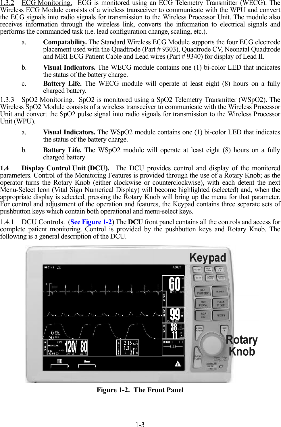

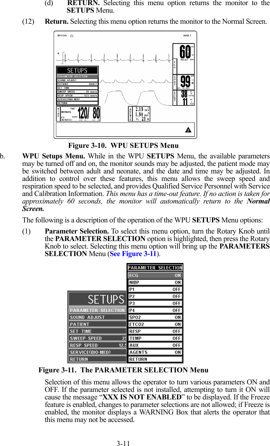


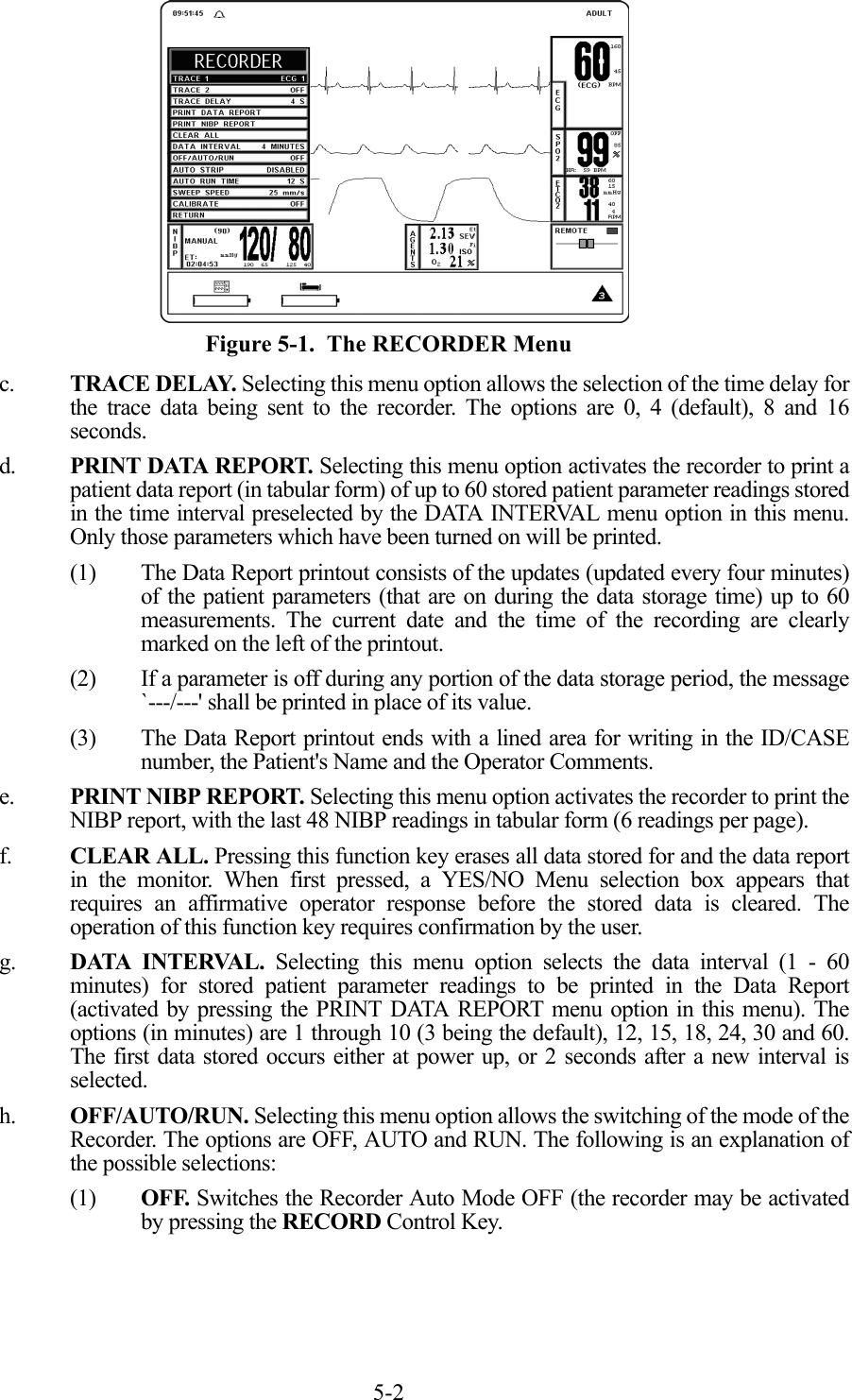
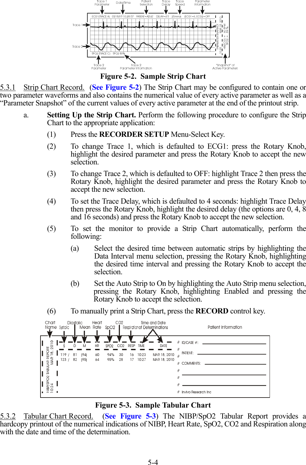
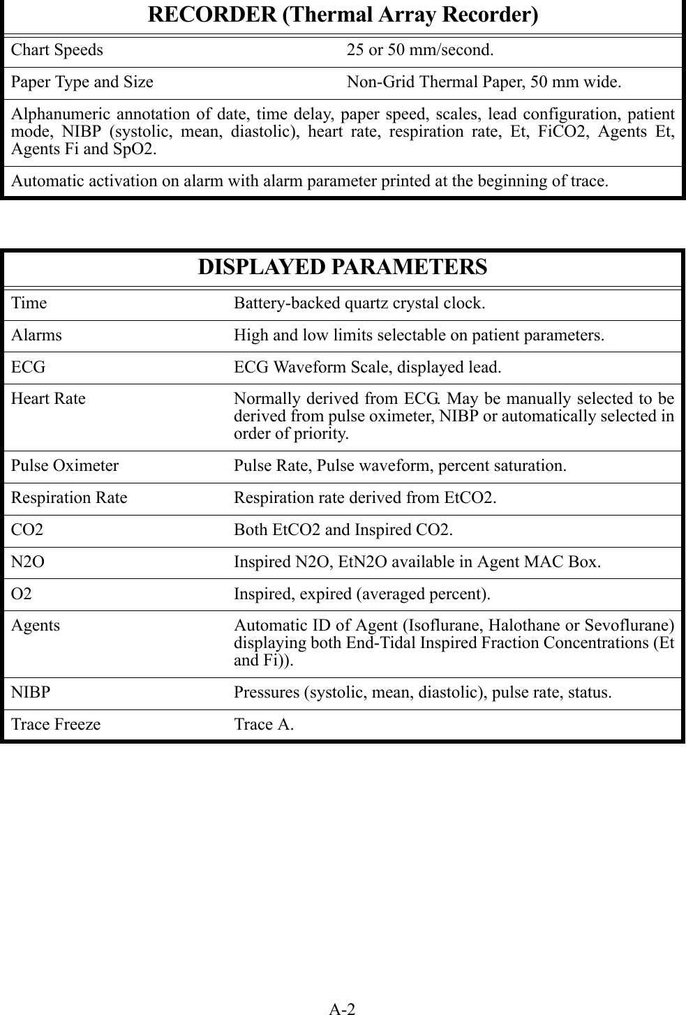
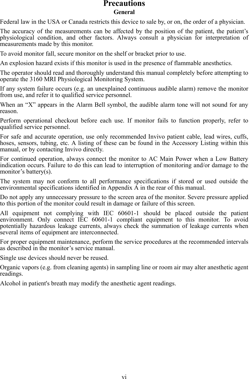
![5-1SECTION 5RECORDING AND TRENDING5.0 RECORDING AND TRENDING.5.1 Introduction. The 3160 MRI Physiological Monitoring System thermal array striprecorder can record one or two waveforms (as selected from the RECORDER Menu). The recorderprints patient parameters on the edge of the strip chart and ends with a “snapshot” patient data report.The Recorder option provides the following features:• Selection of the traces to be sent to the recorder.• High frequency response (Single = 800 samples/second at 25 mm/second speedand Dual = 400 samples/second at 25 mm/second speed) with a bandwidth of 100Hz.• Transmitting a calibration waveform to the recorder.• Total control over the Recorder mode (OFF/AUTO/RUN).• Selection of patient data report for printing.• Selection of data collection intervals for report.• 0 to 16 seconds of trace delay in four increments.• Selection of 25 or 50 mm/second recorder speed (and screen trace speed).• The paper record is automatically annotated with the alphanumeric indication ofdate, time, trace delay, paper speed, scales, lead configuration, mode, heart rate,NIBP (which displays systolic, diastolic and mean blood pressures), respirationrate, EtCO2, SpO2 and Agent Gas ID for expired and inspired breath phases.• If an active alarm limit is violated, the numeric value of the correspondingparameter is printed at the beginning of the automatically activated record.• The recorder uses non-grid thermal paper.5.1.1 Record Key. The RECORD key starts/stops the Recorder upon operator demand. If leftrunning the recorder will continue to supply hard copy output for approximately 25 seconds before itautomatically shuts off.5.2 The RECORDER Menu. The RECORDER Menu provides adjustments that will allowthis monitor to supply concise and up to date printouts suitable to a wide variety of situations. Pressingthe RECORDER SETUP Menu-Select key brings up the RECORDER Menu (See Figure 5-1). Ifthe recorder is not installed, the message “RECORDER OPTION NOT INSTALLED” is displayedon the screen. This menu has a time-out feature. If no action is taken for approximately 60 seconds,the monitor will automatically return to the Normal Screen.The following is a description of the options in the RECORDER Menu:a. TRACE 1. Selecting this menu option allows the selection of the first trace to beoutput to the recorder. The options [depending on currently installed parameters] areECG1 (default), SPO2 and RESP(CO2). If TRACE 2 is off, TRACE 1 is output to therecorder using the full 40 mm width of the printout.b. TRACE 2. Selecting this menu option allows the selection of the second trace to beoutput to the recorder. The options [depending on the currently installed parameters]are OFF (default), ECG1, SPO2 and RESP(CO2).NOTEThe Recorder unit is only available on the DCU.](https://usermanual.wiki/Invivo/DR3160BAS/User-Guide-572237-Page-83.png)