Invivo DR3160BAS Base Dual Transmitter User Manual 9567
Invivo Corporation Base Dual Transmitter 9567
Invivo >
users manual

Invivo Corporation
3160 MRI PHYSIOLOGICAL MONITORING SYSTEM
OPERATIONS MANUAL


i
TABLE OF CONTENTS
Paragraph Number Page Number
List of Figures ........................................................................................................................................... iv
List of Tables.............................................................................................................................................. v
Equipment Classification ........................................................................................................................ v
Precautions ................................................................................................................................................ vi
User Responsibility ................................................................................................................................xiv
3160 MRI Physiological Monitor Accessories.................................................................................. xv
1.0 INTRODUCTION ......................................................................................................... 1-1
1.1 Product Description ......................................................................................................... 1-1
1.1.1 System Mounting................................................................................................. 1-1
1.1.2 System Parameters............................................................................................... 1-1
1.1.3 User Interface....................................................................................................... 1-2
1.1.4 Versatility............................................................................................................. 1-2
1.2 Wireless Processor Unit (WPU) ...................................................................................... 1-2
1.2.1 Operating Environment........................................................................................ 1-2
1.2.2 Power Supply....................................................................................................... 1-2
1.2.3 Battery Operation................................................................................................. 1-2
1.3 Patient Connections ......................................................................................................... 1-2
1.3.1 NIBP and Agent Monitoring................................................................................ 1-2
1.3.2 ECG Monitoring .................................................................................................. 1-3
1.3.3 SpO2 Monitoring ................................................................................................. 1-3
1.4 Display Control Unit (DCU)............................................................................................ 1-3
1.4.1 DCU Controls ...................................................................................................... 1-3
1.4.2 DCU Display........................................................................................................ 1-8
1.5 Cleaning ......................................................................................................................... 1-12
1.5.1 Cleaning Accessories......................................................................................... 1-12
2.0 INSTALLATION........................................................................................................... 2-1
2.1 Introduction...................................................................................................................... 2-1
2.2 Monitor Installation ......................................................................................................... 2-1
2.2.1 Monitor Mounting................................................................................................ 2-1
2.2.2 Preparing the 3160 MRI Physiological Monitoring System for Use................... 2-1
2.2.3 Monitor Start Up.................................................................................................. 2-1
3.0 PREPARATION FOR USE.......................................................................................... 3-1
3.1 Introduction...................................................................................................................... 3-1
3.2 SETUPS Menu................................................................................................................. 3-1
3.3 Store/Recall Setups ........................................................................................................ 3-20
3.4 Monitor Initialization..................................................................................................... 3-21
3.4.1 Default Initialization .......................................................................................... 3-21
3.4.2 Pre-Configured Initialization ............................................................................. 3-21
4.0 PATIENT PARAMETERS........................................................................................... 4-1
4.1 ECG Monitoring .............................................................................................................. 4-1
4.1.1 Patient and Lead Preparation ............................................................................... 4-1
4.1.2 Associated Waveforms and Displays .................................................................. 4-2
4.1.3 The ECG Menu.................................................................................................... 4-2
4.1.4 Alarm Limits........................................................................................................ 4-5
4.1.5 Trended Data........................................................................................................ 4-5
4.1.6 ECG Messages..................................................................................................... 4-5

ii
TABLE OF CONTENTS
Paragraph Number Page Number
4.2 Non-Invasive Blood Pressure (NIBP) Monitoring .......................................................... 4-5
4.2.1 Theory of Oscillometric Measurement ................................................................ 4-6
4.2.2 Patient and Cuff Preparation................................................................................ 4-7
4.2.3 Associated Displays............................................................................................. 4-7
4.2.4 The NIBP Menu................................................................................................... 4-9
4.2.5 NIBP Menu Options ............................................................................................ 4-9
4.2.6 Using the Automatic Interval Mode .................................................................. 4-11
4.2.7 Manually Starting/Stopping a Reading Cycle ................................................... 4-11
4.2.8 Stat Mode Operation.......................................................................................... 4-11
4.2.9 Alarm Limits...................................................................................................... 4-11
4.2.10 Adult vs. Neonatal Mode Operation .................................................................. 4-11
4.2.11 Trended Data...................................................................................................... 4-11
4.2.12 NIBP Messages.................................................................................................. 4-12
4.3 SpO2 Monitoring ........................................................................................................... 4-12
4.3.1 Sensor Positioning ............................................................................................. 4-12
4.3.2 Associated Waveforms and Displays ................................................................ 4-13
4.3.3 SpO2 Menu ........................................................................................................ 4-13
4.3.4 Alarm Limits...................................................................................................... 4-14
4.3.5 Trended Data...................................................................................................... 4-14
4.3.6 SpO2 Messages.................................................................................................. 4-14
4.4 End-tidal CO2 (EtCO2) Monitoring .............................................................................. 4-15
4.4.1 Patient and Sampling Line Preparation ............................................................. 4-15
4.4.2 Water Trap Replacement ................................................................................... 4-17
4.4.3 Associated Waveforms and Displays ................................................................ 4-17
4.4.4 EtCO2 Menu ...................................................................................................... 4-18
4.4.5 Calibration of CO2/N2O Measurement System ................................................ 4-18
4.4.6 Alarm Limits...................................................................................................... 4-19
4.4.7 Trended Data...................................................................................................... 4-19
4.4.8 EtCO2 Messages................................................................................................ 4-19
4.5 Anesthetic Agent/Oxygen Monitoring........................................................................... 4-20
4.5.1 Patient and Tubing Preparation.......................................................................... 4-20
4.5.2 Associated Displays........................................................................................... 4-21
4.5.3 Agent Menu ....................................................................................................... 4-23
4.5.4 Gas Calibration .................................................................................................. 4-23
4.5.5 Alarm Limits...................................................................................................... 4-24
4.5.6 Trended Data...................................................................................................... 4-24
4.5.7 Agent/O2 Messages ........................................................................................... 4-24
4.5.8 Oxygen Monitoring............................................................................................ 4-25
5.0 RECORDING AND TRENDING ................................................................................ 5-1
5.1 Introduction...................................................................................................................... 5-1
5.1.1 Record Key .......................................................................................................... 5-1
5.2 The RECORDER Menu................................................................................................... 5-1

iii
TABLE OF CONTENTS
Paragraph Number Page Number
5.3 Recording Charts ............................................................................................................. 5-3
5.3.1 Strip Chart Record ............................................................................................... 5-4
5.3.2 Tabular Chart Record........................................................................................... 5-4
5.3.3 Trend Chart .......................................................................................................... 5-5
5.3.4 System Data Report ............................................................................................. 5-5
5.4 Loading Recorder Paper .................................................................................................. 5-5
5.5 Trending Feature.............................................................................................................. 5-5
5.5.1 HISTORY Menu Options .................................................................................... 5-6
6.0 ALARMS ........................................................................................................................ 6-1
6.1 Introduction...................................................................................................................... 6-1
6.2 Alarm Limits.................................................................................................................... 6-1
6.2.1 Default (Pre-Set) Alarm Limits ........................................................................... 6-1
6.2.2 Range of High and Low Alarm Limits ................................................................ 6-1
6.3 Alarm Setup ..................................................................................................................... 6-1
6.3.1 Parameter Alarms Status Screen.......................................................................... 6-4
6.4 Turning Alarms Off on Individual Parameters ................................................................ 6-4
6.5 Alarm Violations.............................................................................................................. 6-4
6.6 Adjusting the Alarm Tone Volume ................................................................................. 6-5
6.6.1 Disabling the Alarm Tone.................................................................................... 6-5
6.7 Standby Mode .................................................................................................................. 6-6
7.0 BATTERY OPERATION............................................................................................. 7-1
7.1 Introduction...................................................................................................................... 7-1
7.2 Battery Location and Access ........................................................................................... 7-1
7.3 Loading and Unloading Battery(s) .................................................................................. 7-1
7.4 Battery Charging.............................................................................................................. 7-1
7.5 Battery Operation Time ................................................................................................... 7-1
7.5.1 Battery Low Indication ........................................................................................ 7-1
7.6 Battery Replacement........................................................................................................ 7-1
Specifications............................................................................................................................. A-1
Repair..........................................................................................................................................B-1
Warranty ....................................................................................................................................C-1
Declaration of Conformity ....................................................................................................... D-1
kPa to mmHg Conversion Chart ..............................................................................................E-1
List of Symbols ........................................................................................................................... F-1

iv
LIST OF FIGURES
Figure Number Page Number
1-1 Patient Connection Unit (PCU) ....................................................................................... 1-2
1-2 The Front Panel................................................................................................................ 1-3
1-3 The Top Keypad Set ........................................................................................................ 1-4
1-4 The Middle Keypad Set ................................................................................................... 1-5
1-5 The Bottom Keypad Set................................................................................................... 1-6
1-6 The Normal Screen .......................................................................................................... 1-8
1-7 The Informational Display............................................................................................... 1-8
1-8 The Vital Signs Trace Display......................................................................................... 1-9
1-9 The Vital Signs Numeric Display.................................................................................. 1-10
3-1 The DCU SETUPS Menu ................................................................................................ 3-1
3-2 The RECALL SETUPS Menu......................................................................................... 3-2
3-3 The STORE SETUPS Menu............................................................................................ 3-3
3-4 The PARAMETER SELECTION Menu......................................................................... 3-4
3-5 The SOUND ADJUST Menu .......................................................................................... 3-5
3-6 The SET TIME Menu ...................................................................................................... 3-7
3-7 NETWORK Menu ........................................................................................................... 3-8
3-8 The DCU SERVICE (BIO-MED) Menu ......................................................................... 3-8
3-9 The SYSTEM CONFIG Menu ........................................................................................ 3-9
3-10 WPU SETUPS Menu..................................................................................................... 3-11
3-11 The PARAMETER SELECTION Menu....................................................................... 3-11
3-12 The SOUND ADJUST Menu ........................................................................................ 3-13
3-13 The SET TIME Menu .................................................................................................... 3-14
3-14 The WPU SERVICE (BIO-MED) Menu....................................................................... 3-15
3-15 NIBP TESTS Menu ....................................................................................................... 3-16
3-16 GAS CAL Menu ............................................................................................................ 3-17
3-17 Monitor Calibration YES/NO Menu.............................................................................. 3-18
3-18 Monitor Calibration Information Screen ....................................................................... 3-18
3-19 System Configuration Menu.......................................................................................... 3-19
4-1 ECG Trace and Numerical Displays................................................................................ 4-1
4-2 The ECG Menu................................................................................................................ 4-2
4-3 The ECG SCALE Sub-Menu........................................................................................... 4-3
4-4 The ECG HR SOURCE Sub-Menu ................................................................................. 4-4
4-5 Oscillometric Measurement Method ............................................................................... 4-6
4-6 The NIBP Display............................................................................................................ 4-7
4-7 The NIBP Menu............................................................................................................... 4-8
4-8 The NIBP INTERVAL Menu.......................................................................................... 4-9
4-9 The HISTORY Menu..................................................................................................... 4-10
4-10 SpO2 Display................................................................................................................. 4-13
4-11 The SpO2 Menu............................................................................................................. 4-13
4-12 The SpO2 SIZE Menu ................................................................................................... 4-14
4-13 The Patient Sampling Circuit......................................................................................... 4-16
4-14 Water Trap Installation Diagram ................................................................................... 4-16
4-15 The EtCO2 Display........................................................................................................ 4-17
4-16 The EtCO2 Menu........................................................................................................... 4-18
4-17 Anesthetic Agents Display............................................................................................. 4-20
5-1 The RECORDER Menu................................................................................................... 5-2

v
LIST OF FIGURES
Figure Number Page Number
5-2 Sample Strip Chart........................................................................................................... 5-4
5-3 Sample Tabular Chart ...................................................................................................... 5-4
5-4 System Data Report ......................................................................................................... 5-5
5-5 Loading the Recorder Paper ............................................................................................ 5-5
5-6 The HISTORY Menu....................................................................................................... 5-6
5-7 The MULTI TRENDS Menu........................................................................................... 5-7
5-8 The Trend SELECT Menu............................................................................................... 5-7
5-9 Sample Multi Trends Printout.......................................................................................... 5-8
6-1 The ALARMS Menu ....................................................................................................... 6-1
6-2 GAS ALARMS (Anesthetic Agents Alarm Limit) Menu ............................................... 6-3
LIST OF TABLES
Table Number Page Number
4-1 Agent Display During Mixed Agent Conditions ........................................................... 4-22
4-2 Agent Display During Mixed Agent Conditions .......................................................... 4-23
6-1 Alarm Limit Factory Default Settings ............................................................................. 6-7
6-2 Range of Alarm Limits .................................................................................................... 6-8
EQUIPMENT CLASSIFICATION
Classification according to IEC-60601-1
According to the type of protection against
electrical shock:
Class I equipment.
According to the degree of protection against
electrical shock:
Type CF (defibrillator-proof) equipment.
According to the degree of protection against
harmful ingress of water:
Ordinary equipment (enclosed equipment
without protection against ingress of water).
According to the methods of sterilization or
disinfection:
Non-sterilizable. Use of liquid surface
disinfectants only.
According to the mode of operation: Continuous operation.
Equipment not suitable for use in the presence of flammable anesthetic mixture with air or with
oxygen or nitrous oxide.
vi
Precautions
General
Federal law in the USA or Canada restricts this device to sale by, or on, the order of a physician.
The accuracy of the measurements can be affected by the position of the patient, the patient’s
physiological condition, and other factors. Always consult a physician for interpretation of
measurements made by this monitor.
To avoid monitor fall, secure monitor on the shelf or bracket prior to use.
An explosion hazard exists if this monitor is used in the presence of flammable anesthetics.
The operator should read and thoroughly understand this manual completely before attempting to
operate the 3160 MRI Physiological Monitoring System.
If any system failure occurs (e.g. an unexplained continuous audible alarm) remove the monitor
from use, and refer it to qualified service personnel.
When an “X” appears in the Alarm Bell symbol, the audible alarm tone will not sound for any
reason.
Perform operational checkout before each use. If monitor fails to function properly, refer to
qualified service personnel.
For safe and accurate operation, use only recommended Invivo patient cable, lead wires, cuffs,
hoses, sensors, tubing, etc. A listing of these can be found in the Accessory Listing within this
manual, or by contacting Invivo directly.
For continued operation, always connect the monitor to AC Main Power when a Low Battery
indication occurs. Failure to do this can lead to interruption of monitoring and/or damage to the
monitor’s battery(s).
The system may not conform to all performance specifications if stored or used outside the
environmental specifications identified in Appendix A in the rear of this manual.
Do not apply any unnecessary pressure to the screen area of the monitor. Severe pressure applied
to this portion of the monitor could result in damage or failure of this screen.
All equipment not complying with IEC 60601-1 should be placed outside the patient
environment. Only connect IEC 60601-1 compliant equipment to this monitor. To avoid
potentially hazardous leakage currents, always check the summation of leakage currents when
several items of equipment are interconnected.
For proper equipment maintenance, perform the service procedures at the recommended intervals
as described in the monitor’s service manual.
Single use devices should never be reused.
Organic vapors (e.g. from cleaning agents) in sampling line or room air may alter anesthetic agent
readings.
Alcohol in patient's breath may modify the anesthetic agent readings.
vii
Precautions
Electrical Safety
To avoid an electrical hazard, never immerse the unit in any fluid or attempt to clean it with liquid
cleaning agents. Always disconnect monitor from AC Main Power before performing cleaning or
maintenance.
If monitor becomes accidentally wet during use, discontinue operation of the monitor until all
affected components have been cleaned and permitted to dry completely. Contact your local
Invivo representative if additional information is required.
Shock hazard exists if operated without chassis cover. Refer servicing to qualified service
personnel only.
For continued protection against fire hazard, replace fuses with same type and rating only.
Connect the monitor only to a three-wire, grounded, hospital-grade receptacle. The three-
conductor plug must be inserted into a properly wired three-wire receptacle; if a three-wire
receptacle is not available, a qualified electrician must install one in accordance with the
governing electrical code.
Do not under any circumstances remove the grounding conductor from the power plug.
Avoid use of electrical power extension cords. Electrical power extension cords may create a
safety hazard by compromising the grounding integrity of the monitor.
None of the monitor interconnection ports on the rear of the monitor (e.g. Communication Ports,
Auxiliary Input/Output port [AUX I/O], ECG Sync Input [ECG SYNC IN], Keyboard or Video
Input) are intended for direct patient connection. An electric shock hazard can exist if the patient
is electrically connected to any of these connections.
This monitor and its listed accessories may be safely powered by the voltages 110-120/220-240
VAC having a frequency of 50 or 60 Hz.
If the integrity of the earth ground conductor of the AC mains power cable is in doubt, operate the
monitor on internal battery power until proper earth ground connection is confirmed.
Patient Safety
Constant attention by a qualified individual is needed whenever a patient is under anesthesia or
connected to a ventilator. Some equipment malfunctions may occur in spite of equipment or
monitor alarms.
Always test sampling line adapter for a tight connection and proper operation before attaching to
a patient.
As with all medical equipment, carefully route patient cabling to reduce the possibility of patient
entanglement or strangulation.
Occupational Safety
Connect the sample gas outlet on the monitor's rear panel to a scavenging system to prevent
pollution of room air.
Handle the Patient Sampling Line and its contents as you would any body fluid. Infectious hazard
may be present.
MRI Use Precautions
Certain components of this device will be affected by the magnetic and radio frequency fields present
in your MRI System. Confer with your MRI physicist and/or Radiology staff to identify the proper
placement and use areas for the monitor and its accessories, as defined on the monitor or accessory
labeling. Failure to properly place the monitor and its accessories in the Magnet Room will result in
monitor failure, and possible patient or user injury. Always position the 3160 MRI Physiological
Monitoring System at, or outside, the 5000 Gauss (0.5T) field line of the MRI system. A slight
distortion of the MRI magnetic field homogeneity or possible damage to either the monitor's NIBP or
EtCO2 pump could occur.

viii
Precautions
MRI Use Precautions (Continued)
Always verify proper communicationof the 3160 MRI Physiological Monitoring System with
the Remote Monitor prior to patient use.
MRI Magnet Room Placement. The 3160 MRI Physiological Monitoring System is designed to be
used in conjunction with a remote monitor. The 3160 MRI Physiological Monitoring System is
specially designed not to interfere with MRI operations and may be used inside the MRI Magnet Room
in any location at or outside the 5000 Gauss (0.5T) Field Line of the MRI System. If brought closer
than the 5000 Gauss Field Line, the NIBP monitor pump and EtCO2 pump may fail to operate.
The Remote Monitor is also specifically designed not to interfere with MRI operations, and may be
used in the Magnet Room at or outside the 1000 Gauss (0.1T) Field Line of the MRI System. If
brought closer than the 1000 Gauss Field Line, monitor damage (failure to operate) may result.
Risk of RF current burn. Cables which become inadvertently looped during MRI act as conductive
lines for RF induced currents. When lead wires or other cables form a conductive loop in contact with
the patient's tissue, minor to severe burning can result.
Perform the following to minimize risk of RF current burn:
a. Place cables and lead wires neatly in straight alignment with no looping.
b. Keep the length of lead wires and patient cable within the bore to a minimum.
c. RF burn risk increases when multiple sensors/cables are in use. Such combinations are
not recommended.
d. The high radio frequency (RF) power used in MRI scanning poses an ever-present risk
of excessive heat at the monitoring sites and, therefore, the risk of RF current burn.
Should power levels greater than S.A.R. of 4 w/kg peak (0.4 w/kg average) be
used, the risk of patient burn greatly increases. As a result, monitoring of ECG at
power levels of greater than 4 w/kg peak (0.4 w/kg average) is not recommended for
the general patient population. Such monitoring should only be attempted on conscious
patients with good temperature reflex so they may warn the operator of excessive heat
at the monitoring sites.
e. High RF Power may cause patient heating or burns. For scans with average S.A.R. > 1
w/kg, limit scan time to 5 minutes and pause at least 3 minutes between scans to allow
ECG Cable to cool.
MRI Compatibility
The Quadtrode® MRI ECG Electrode Pad, and ECG Patient Lead Wires and Cable, are compatible
with Magnetic Resonance Imaging (MRI) Systems within the following guidelines:
• MRI systems with static magnetic field strengths up to 1.5 Tesla.
• Usable within the MRI system bore with Specific Absorption Ratios (S.A.R.'s) up to 4.0 w/kg
(peak). Use with higher S.A.R.'s greatly increases the risk of patient burns.
• Non-Magnetic materials are used in the construction of these assemblies.
• If scanned directly across the plane of the ECG electrode element, a slight image distortion may
be seen at the skin surface where the electrode element is positioned.
ix
Precautions
ECG
An inoperative ECG monitor is indicated by absence of an ECG waveform and a simultaneous
Lead Fail alarm.
For best ECG, Heart Rate, S-T Segment, and/or Respiration monitoring, always select the
optimum lead configuration which has the least artifact and largest waveform(s) being detected
for monitoring use.
Failure to respond to a Lead Fail alarm will cause a lapse in your patient’s monitoring. Always
respond promptly to this and any other alarms.
Heart rate values may be adversely affected by cardiac arrhythmia, or by operation of electrical
stimulators.
NIBP
Always use recommended NIBP cuffs and hoses. Avoid compression or restriction of NIBP cuff
hose.
When using the NIBP portion of this instrument to measure blood pressure, remember that the
patient’s blood pressure readings are not continuous, but are updated each time a blood pressure
measurement is taken. Set a shorter interval for more frequent updating of the patient’s blood
pressure.
Do not attach the cuff to a limb being used for infusion. Cuff inflation can block infusion, possibly
causing harm to the patient.
Frequent NIBP measurements can cause pooling of the blood in the limb (hemostasis), and
peripheral tissue/nerve damage. Allow sufficient time between measurements for blood
recirculation to prevent pooling of the blood in the limb.
Arrhythmic and/or erratic heart beats (or severe motion artifact, such as tremors or convulsions)
can result in inaccurate readings and/or prolonged measurements. If questionable readings are
obtained, re-check patient’s vital signs by alternate means before administering medication.
To prevent possible nerve damage to the limb, apply the NIBP cuff as recommended by current
American Heart Association (AHA) guidelines for blood pressure monitoring.
To ensure accurate and reliable measurements, use only recommended patient cuffs/hoses. For
best accuracy, use the appropriate cuff size for each patient as recommended by the current AHA
guidelines for blood pressure monitoring.
Always tighten the cuff air hose connections snugly into place for proper operation.
Some reusable NIBP cuffs contain a medical-grade latex rubber. Patients sensitized to latex
rubber can have an allergic reaction when exposed to this material. Avoid the use of cuffs which
contain latex rubber on patients who are allergic to this material.
Routinely inspect the cuff and hose assemblies for proper attachment and orientation. Replace
cuff and/or hose assemblies with cracks, holes, tears, cuts, etc. that could cause leaks in the
system. If cuff and/or hose assemblies with damage which could result in leaks are used,
prolonged and/or inaccurate patient readings could result.
To prevent skin abrasion, apply and remove cuff carefully. Keep Velcro® (hook and latch)
retention areas away from the skin.
x
Precautions
SpO2
Avoid placement of the SpO2 sensor on the same limb with an inflated blood pressure cuff. Cuff
inflation could result in inaccurate readings and false alarm violations.
SpO2 monitoring requires the detection of valid pulses to correctly determine SpO2 and Heart
Rate values. During conditions of gross artifact, or in the absence of valid pulses, the SpO2 /rate
values may not be correct.
The SpO2 monitoring portion of this monitor is intended to measure arterial hemoglobin oxygen
saturation of functional hemoglobin (saturation of hemoglobin functionally available for
transporting oxygen in the arteries). Significant levels of dysfunctional hemoglobins, such as
carboxyhemoglobin or methemoglobin, may affect the accuracy of the measurement. Also,
Cardiogreen and other intravascular dyes may, depending on their concentration, affect the
accuracy of the SpO2 measurement.
Always shield the SpO2 sensor from extraneous incident light sources. Such extraneous light can
cause SpO2 reading or pulse detection errors.
Frequently inspect the SpO2 sensor site for possible pressure tissue necrosis during prolonged
monitoring. Reposition the sensor at least every four (4) hours. Special care should be exercised
when tape is used to secure the sensor, as the stretch memory properties of most tapes can easily
apply unintended pressure to the sensor site.
The numeric measurement values are updated every one (1) second on the monitor display.
A pulse oximeter should be considered an early warning device. As a trend towards patient
deoxygenation is indicated, blood samples should be analyzed by a laboratory co-oximeter to
completely understand the patient’s condition.
The pulse oximeter feature in this monitor is designed to display functional SpO2 values.
The pulse oximeter pulsatile waveform is not proportional to the pulse volume, but adjusts the
waveform amplitude as needed for proper viewing.
All monitor alarms are categorized as medium priority, unless otherwise specified.
Arrhythmic and/or erratic heart beats (or severe motion artifact, such as tremors or convulsions)
can result in inaccurate readings and/or prolonged measurements. If questionable readings are
obtained, re-check patient’s vital signs by alternate means before administering medication.
Respiration
When setting up respiration monitoring, always observe and adjust the respiration gain of the
monitor while watching the patient’s breathing efforts before completing selection of the gain
setting. Failure to do this can result in inaccurate readings, or false respiration detection.
End-tidal CO2 (EtCO2)
Verify that the patient’s breathing efforts and timing coincide with the monitor’s waveform before
completion of the patient set-up.
The EtCO2/N2O measurements are automatically pressure compensated over an ambient pressure
range from 576 to 788 mmHg.
The EtCO2/N2O measurement displays the sampled value within 1 second of when the gas was
sampled.
The alarm tone volume exceeds 60 dBA at a distance of 1 meter when the alarm tone volume
adjustment is set above selection number 8.
Frequently inspect the EtCO2 patient tubing for proper gas flow. Avoid kinking of the EtCO2
patient tubing that can result in leaking, reduction, or cut-off of the sample gas flow. Inaccurate gas
measurements could result.
xi
Precautions
End-Tidal CO2 (Continued)
EtCO2 patient tubing and its associated components are intended for single-patient use only.
Avoid cleaning or disinfecting these items for reuse. Inaccurate gas measurements could result.
To prevent inaccurate or missed readings, keep the EtCO2 patient tubing clear of any moving
mechanisms which may kink, cut or dislodge the patient tubing.
Do not overtighten the patient gas sample line to the water trap connector. Overtightening this
connector can cause failure of the water trap assembly and resultant inaccurate (artificially low)
patient gas measurements.
Avoid connecting the EtCO2 calibration gas canister to the monitor by any method other than
with the designated calibration tubing. Connecting by any other method could invalidate the
calibration, and/or damage the monitor.
Respiration rate measurement errors could result during ventilation rates above 80 breaths per
minute.
Anesthetic Agents
Inadequate ventilation of the monitor may cause inaccurate readings or damage to electronic
components.
Ensure that the exhaust gas is not removed from the monitor under too strong a vacuum. To
prevent this condition, there must always be an opening to the room air. Too high a vacuum level
may change the operating pressure of the monitor and cause inaccurate readings or internal
damage.
Inspect waste gas line for deterioration on a regular basis. Replace as needed.
Remove sampling line from patient airway whenever nebulized medications are being delivered.
Use only Invivo sampling lines and accessories; other sampling lines may cause inaccurate
readings and malfunctions.
Some Hydrocarbons (e.g. Acetone, Methane) may cause a mixed agent alarm to occur.
Replace the sampling line and inspect water trap between each patient use.
Do not overtighten the patient gas sample line to the water trap connector. Overtightening this
connector can cause failure of the water trap assembly and resultant inaccurate (artificially low)
patient gas measurements.
Routinely inspect the hose assemblies for proper attachment and orientation. Replace hose
assemblies with cracks, holes, tears, cuts, etc. that could cause leaks in the system. If hose
assemblies with damage which could result in leaks are used, prolonged and/or inaccurate patient
readings could result.
If questionable anesthetic agent gas measurements are observed, recheck patient connections,
anesthesia gas machine and/or vaporizer before re-adjusting anesthesia delivery.
Routinely verify the monitor’s internal barometric pressure reading with local conditions during
the initial start-up period.
xii
Precautions
Anesthetic Agents (Continued)
With no gas reading (Agent Icon box with white X for agent identification and agent values of “--
-”) when Agent Vaporizer is first turned on, it may take 30 seconds to 1.5 minutes for agent
identification and reading to be displayed. Once identification is established, changes in
concentration are virtually immediate. With a 200% change in concentration, an auto Zero will
occur, and full accuracy of the changed concentration will be accomplished within approximately
30 seconds.
Whenever the 3160 MRI Physiological Monitoring System Agent sensor changes from steady state
condition, the 3160 MRI Physiological Monitoring System will perform an auto zero to restabilize
the sensor readings. During this time, 15 seconds to 1.5 minutes, it is possible for a false
identification and concentration value to occur. Examples are as follows:
a. No gas, during warm-up and when sample line is disconnected.
b. Applying sample line for the first time.
c. When switching from one Agent to another.
d. Applying N2O in concentrations of 70% or more.
e. Going from N2O of greater than 50% to 0%.
f. When going from high Agent concentrations to low or off.
Other
This product, or any of its parts, should not be repaired other than in accordance with written
instructions provided by Invivo, or altered without prior written approval of Invivo Corporation.
The user of this product shall have the sole responsibility for any malfunction which results from
improper use, faulty maintenance, improper repair, damage, or alteration by anyone other than
Invivo, or its authorized service personnel.
This monitor is equipped with a demonstration mode which displays simulated electronic patient
data for training or demonstration purposes. Do not attach a patient to the monitor whenever this
simulation is present on the monitor display (“SIMULATION” can also be seen in the screen
center). Failure to properly monitor the patient could result.
The patient connector inputs for all parameters are protected against the use of a defibrillator by
internal circuitry, and when the recommended patient cables or accessories are used. The use of
this circuitry and these recommended cables and accessories also protects against the hazards
resulting from use of high frequency surgical equipment.
There are no known electromagnetic or other hazardous interference between the monitor and
other devices. However, care should be taken to avoid the use of cellular phones or other
unintended radio-frequency transmitters in the proximity of the monitoring system.
This monitor uses rechargeable batteries which contain hazardous material, which must be
recycled, or disposed of properly. For proper disposal methods, contact your local Invivo
representative or distributor.
Avoid ammonia, phenol or acetone based cleaners for they may damage the monitor surface.
Dispose of the monitor and parts thereof according to local regulations.

xiii
Precautions
Other (Continued)
Notes, Cautions and Warnings. In the body of the manual notes, cautions and warnings are as
shown below to make them stand out on the page. The following is a description of the format and
meaning of Notes, Cautions and Warnings:
a. Notes. Notes are presented as shown below. Notes contain supplemental information
which Invivo has deemed especially important.
b. Cautions. Cautions are presented as shown below. Cautions are used for the words
and/or terms which alert the user to the possibility of a problem with the device
associated with its use or misuse. Such problems may include device malfunctions,
device failure, damage to the device or damage to other property.
c. Warnings. Warnings are presented as shown below. Warnings are used for the words
and/or terms which alert the user to possible injury, death or other serious adverse
reactions associated with the use or misuse of the device.
NOTE
This is a sample note.
CAUTION
This is a sample caution.
WARNING
This is a sample warning.
xiv
USER RESPONSIBILITY
This product will perform in conformity with the description contained in this operators manual
and accompanying labels and/or inserts, when assembled, operated, maintained and repaired in
accordance with the instructions provided. This product must be checked and calibrated
periodically. A malfunctioning product should not be used. Parts that are broken, missing, plainly
worn, distorted or contaminated should be replaced immediately. Should such repair or
replacement become necessary refer unit to qualified service personnel. This product or any of its
parts should not be repaired other than in accordance with written instructions provided by the
manufacturer, or altered without written approval of Invivo. The user of the product shall have the
sole responsibility for any malfunction which results from improper use, faulty maintenance,
improper repair, damage or alteration by anyone other than Invivo or Invivo authorized service
personnel.
Using this Manual. Whenever the various options are discussed, “XXX” is used to indicate a
variable setting. It is required that every operator read this manual completely, including any
patient information in sections about monitoring features the operators monitor does not have,
before attempting to operate the 3160 MRI Physiological Monitoring System.
The figures contained in this manual show a fully equipped monitor. Therefore, figures within
this manual may depict monitoring features that your monitor may not contain. For information
on features and enhancements that are not contained on your monitor, contact Invivo at (407) 275-
3220.
Precautions (listed earlier in this section) cover of wide ranges of information crucial to the safe
monitoring of patients. It is required that every operator read the PRECAUTIONS completely,
including the Precautions associated with monitoring features that the operators monitor does not
have, before attempting to operate the 3160 MRI Physiological Monitoring System.
This device is covered under one or more of the following U.S. Patents: 5,482,036; 5,490,505;
5,632,272; 5,685,299; 5,758,644; 5,769,785; 6,002,952; 6,036,642; 6,067,462; 6,206,830;
6,157,850; 6,277,081 and international equivalents. U.S.A. and international patents pending.
Possession or purchase of this device does not convey any express or implied license to use the
device with replacement parts which would, alone, or in combination with this device, fall within
the scope of one or more of the patents relating to this device.
For further information or assistance with this product:
Invivo Corporation
407-275-3220 or 800-331-3220

xv
3160 MRI Physiological Monitor Accessories
ECG
Item Description Part Number
Quadtrode® MRI ECG Electrodes, 50/box .......................................................................................9303N
MRI ECG Patient Lead Wire Set..........................................................................................................9218
ECG/EEG Skin Prep Gel, 1 tube 4 ounce ............................................................................................9009
Non-Invasive Blood Pressure
Reusable BP Cuffs and Hoses
Twin-Lumen Adult Air Hose (18 ft. length) .................................................................................... 9010M
Single-Lumen Neonatal NIBP Air Hose (18 ft. length) ............................................................... 9010NM
Infant MRI BP Cuff......................................................................................................................9050MNL
Pediatric MRI BP Cuff .................................................................................................................9060MNL
Adult Standard MRI BP Cuff.......................................................................................................9070MNL
Adult Large Arm MRI BP Cuff ...................................................................................................9080MNL
Adult Thigh MRI BP Cuff ...........................................................................................................9090MNL
Disposable BP Cuffs
Neonatal NIBP Cuff, Disposable, Size A, Velcro........................................................................ AN01AV
Neonatal NIBP Cuff, Disposable, Size B, Velcro ........................................................................ AN02AV
Neonatal NIBP Cuff, Disposable, Size C, Velcro ........................................................................ AN03AV
End-Tidal CO2
EtCO2 Sampling Kit...........................................................................................................................9010D
Contains 20 foot co-extruded sampling tube polyethylene inner core with PVC jacket, Nafion®
tube, elbow adapter and 0.8 micron disk filter.
Adult EtCO2 Cannula ...........................................................................................................................9012
Pediatric EtCO2 Cannula ......................................................................................................................9013
SpO2
Spare Wireless Pulse Oximeter Module............................................................................................... 9311
SpO2 Grip Sensor............................................................................................................................... 9399B

1-1
SECTION 1
INTRODUCTION
1.0 INTRODUCTION.
This manual describes a fully configured monitor, and may include features and/or options that
are not included in your monitor. For additional information, contact your local sales
representative, or Invivo Customer Service.
1.1 Product Description. The Model 3160 MRI Physiological Monitoring System is designed
to assist clinicians in monitoring patient vital signs in the midst of the dynamic and evolving Magnetic
Resonance environment. A combination of the latest wireless communication, radio frequency (RF)
shielding, digital signal processing (DSP), and adaptable mounting technologies address the challenges
associated with patient monitoring in the MRI area. Built on Invivo’s strong heritage in MRI patient
vital signs monitoring, the 3160 provides accurate, continuous, and reliable performance during all
phase of MRI applications.
The standard 3160 configuration consists of wireless electrocardiogram (ECG), wireless pulse
oximetry (SpO2), and non-invasive blood pressure (NIBP). Optional parameters include end-tidal
CO2 and anesthetic agents.
The 3160 system consists of the following components:
a. Wireless Processing Unit. The Wireless Processing Unit (WPU) houses the
circuitry and hardware for support of the standard and optional patient monitoring
parameters. The transceivers and antennas that support wireless communication
with the ECG and SpO2 modules as well as the Display Controller Unit are also
part of the WPU. The unit is powered by an AC – DC power adapter or two
removable batteries that are recharged by the same power adapter. The batteries
provide 8 hours of continuous operation.
b. Patient Connection Unit. The Patient Connection Unit (PCU) contains the
connectors that support all the non-wireless parameters (i.e. NIBP, EtCO2, etc.)
c. Display Controller Unit. The WPU communicates to the Display Controller Unit
(DCU) via a bi-directional 2.4 GHz communication link. The large color LCD
display, keypad, and recorder of the DCU form an easy-to-use user interface for
display, control, and documentation of the system patient monitoring parameters.
d. Wireless ECG Module. The Wireless ECG (WECG) module communicates two
leads of ECG simultaneously to the WPU. These two leads of ECG can be
displayed at the DCU and are output from the WPU unit for interface to the MRI
system cardiac gating input.
e. Wireless SpO2 Module. The Wireless SpO2 (WSpO2) communicates the SpO2
value and pulse waveform to the WPU. The information is available for display at
the DCU and is output from the WPU for interface to the MRI system pulse
peripheral gating input.
1.1.1 System Mounting. The Model 3160 MRI Physiological Monitoring System is built upon an
adaptable mounting platform where the system can be configured in a traditional pole mount
configuration or mounted directly onto the MRI table. The MRI table mount provides an effective
means of allowing the Model 3160 to travel along with the patient on the MRI table thus improving
throughput and efficiency.
1.1.2 System Parameters. The 3160 MRI Physiological Monitor System Parameters allow
simultaneous processing and display of up to five (5) parameters, three (3) waveforms and associated
numeric values from each different parameter. All the Patient Information is clearly displayed on a Flat
Panel Display Screen.
1-2
The 3160 MRI Physiological Monitoring System includes the following Vital Sign
Parameters:
1.1.3 User Interface. A simple to use interface has been developed to minimize operator learning
time. On the Display Control Unit (DCU), there is a Rotary Knob (which detents from selection to
selection) that is used to access the parameter menu's, access the various setup features and finalize any
changes to the setup of the monitor. Frequently used menus (such as: Alarms, Trends and Recorder)
have a Control Key which, when pressed, will open the associated menu. On the Wireless Processor
Unit (WPU), the operator needs an external display and a keyboard to access the various features.
1.1.4 Versatility. With its diverse offering of vital sign parameters, the 3160 MRI Physiological
Monitoring System may be configured to meet the monitoring needs of a wide spectrum of patients
from Neonate to Adults. Every available parameter may be easily accessed and adjusted to the unique
needs, condition and situation of each patient.
1.2 Wireless Processor Unit (WPU). The WPU contains wireless transceivers, data acquisition
and processing circuitry that communicate with the wireless Display Control Unit (DCU), ECG
(WECG) module and SpO2 (WSpO2) module.
1.2.1 Operating Environment. The WPU is designed to operate at the 5,000 Gauss line in the
generated RF field of an MRI system measured from the center line of the bore.
1.2.2 Power Supply. The WPU Power Supply is designed to operate on the floor at least 10 feet
from a 1.5 Tesla unshielded MRI system (200 Gauss). When attached, the power supply charges the
WPU battery pack whether the WPU is operating or not.
1.2.3 Battery Operation. The WPU will operate at least eight (8) hours with EtCO2 and all optional
devices running with NIBP performing automatic readings at five (5) minute intervals.
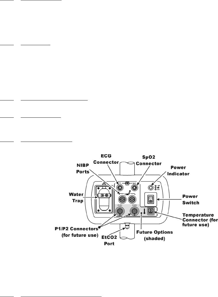
Figure 1-1. Patient Connection Unit (PCU)
1.3 Patient Connections. The physical patient connections for NIBP and the Anesthetic Agents
options are located on the Patient Connection Unit (PCU, See Figure 1-1). ECG, SpO2 and
Respiration all use wireless technology to deliver their measurements to the Wireless Processor Unit
(WPU).
1.3.1 NIBP and Agent Monitoring. The PCU contains the physical connections for the Non-
Invasive Blood Pressure (NIBP) and, when installed, the optional Anesthetic Agents parameters. If
Anesthetic Agents is installed, the PCU also contains a water trap to prevent moisture contamination of
the agent components.
a. Operating Environment. The PCU is designed to operate at the 5,000 Gauss line in
the generated RF field of an MRI system measured from the center line of the bore.
• Single Lead ECG • Pulse Oximetry • NIBP
• EtCO2 • Respiration • Anesthetic Agents
1-3
1.3.2 ECG Monitoring. ECG is monitored using an ECG Telemetry Transmitter (WECG). The
Wireless ECG Module consists of a wireless transceiver to communicate with the WPU and convert
the ECG signals into radio signals for transmission to the Wireless Processor Unit. The module also
receives information through the wireless link, converts the information to electrical signals and
performs the commanded task (i.e. lead configuration change, scaling, etc.).
a. Compatability. The Standard Wireless ECG Module supports the four ECG electrode
placement used with the Quadtrode (Part # 9303), Quadtrode CV, Neonatal Quadtrode
and MRI ECG Patient Cable and Lead wires (Part # 9340) for display of Lead II.
b. Visual Indicators. The WECG module contains one (1) bi-color LED that indicates
the status of the battery charge.
c. Battery Life. The WECG module will operate at least eight (8) hours on a fully
charged battery.
1.3.3 SpO2 Monitoring. SpO2 is monitored using a SpO2 Telemetry Transmitter (WSpO2). The
Wireless SpO2 Module consists of a wireless transceiver to communicate with the Wireless Processor
Unit and convert the SpO2 pulse signal into radio signals for transmission to the Wireless Processor
Unit (WPU).
a. Visual Indicators. The WSpO2 module contains one (1) bi-color LED that indicates
the status of the battery charge.
b. Battery Life. The WSpO2 module will operate at least eight (8) hours on a fully
charged battery
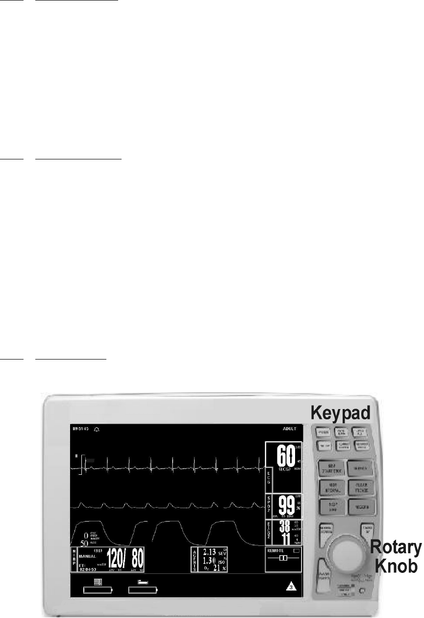
1.4 Display Control Unit (DCU). The DCU provides control and display of the monitored
parameters. Control of the Monitoring Features is provided through the use of a Rotary Knob; as the
operator turns the Rotary Knob (either clockwise or counterclockwise), with each detent the next
Menu-Select Icon (Vital Sign Numerical Display) will become highlighted (selected) and, when the
appropriate display is selected, pressing the Rotary Knob will bring up the menu for that parameter.
For control and adjustment of the operation and features, the Keypad contains three separate sets of
pushbutton keys which contain both operational and menu-select keys.
1.4.1 DCU Controls. (See Figure 1-2) The DCU front panel contains all the controls and access for
complete patient monitoring. Control is provided by the pushbutton keys and Rotary Knob. The
following is a general description of the DCU.
Figure 1-2. The Front Panel
1-4
a. The Rotary Knob. The Rotary Knob is located to the right of the Display Screen. The
function of the Rotary Knob is menu specific. For this reason, its various functions are
described throughout this document where it is used; in general, however, the Rotary
Knob operates as described below:
(1) As the Rotary Knob is rotated, either clockwise or counterclockwise, the
monitor display “scrolls” through the various screen items (screen icons, menu
options and patient parameters) which are available for selection. When the
appropriate item is “highlighted,” it may be selected by pressing and releasing
the Rotary Knob. All menus have a RETURN option which will return the
monitor to the previous menu selection.
(2) During normal operation each active parameter has a Menu-Select icon on the
screen. When the Rotary Knob is rotated, the Menu-Select icon which is being
pointed at becomes “highlighted.” Rotating the Rotary Knob will cause the
monitor to “scroll through” the available menu selections. Once the appropriate
Menu-Select icon is highlighted, pressing the Rotary Knob completes the
selection and brings up the required menu. Once the menu is selected, the
Rotary Knob is used to scroll through the available choices and make
adjustments to the selected parameter. The following Menu-Select Icons may
be available on the Normal Screen (depending on which parameters are
available, enabled and turned on): ECG, NIBP, SpO2, EtCO2 and Agents.
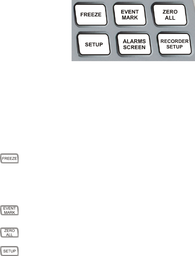
Figure 1-3. The Top Keypad Set
b. The Top Keypad Set. (See Figure 1-3) There are six push keys in the top keypad set.
The top three (FREEZE, EVENT MARK and ZERO ALL) provide direct control of
a monitor feature while the bottom three (SETUP, ALARMS SCREEN and
RECORDER SETUP) provide access to operational menus. The six push keys are
described below:
(1) FREEZE. The 3160 MRI Physiological Monitoring System freezes the
ECG waveform from Trace A for closer examination upon user demand.
When the ECG trace is active, pressing the FREEZE key will freeze it into the
Trace B location while Trace A remains active. When the trace is frozen,
pressing the FREEZE key will release it. A “Blue Box” appears around the
frozen waveform as a visual indication that the waveform is not active. While
the Freeze feature is active, the monitor will not allow any changes to the
Parameter Setups or Display; if the operator attempts to access the
PARAMETER SELECTION menu, a WARNING Box alerts the operator
that entry to the selected menu is not allowed while FREEZE is enabled.
(2) EVENT MARK. The EVENT MARK key prints a marker on the ECG
Recorder Strip when the printer is running. If the printer is not running,
pressing this key has no effect.
(3) ZERO ALL. This feature is not available. Pressing this key will display a
dialog box that alerts the operator that no Invasive Pressures are enabled.
(4) SETUP. The SETUP key allows the operator to access the various available
setup options.
1-5
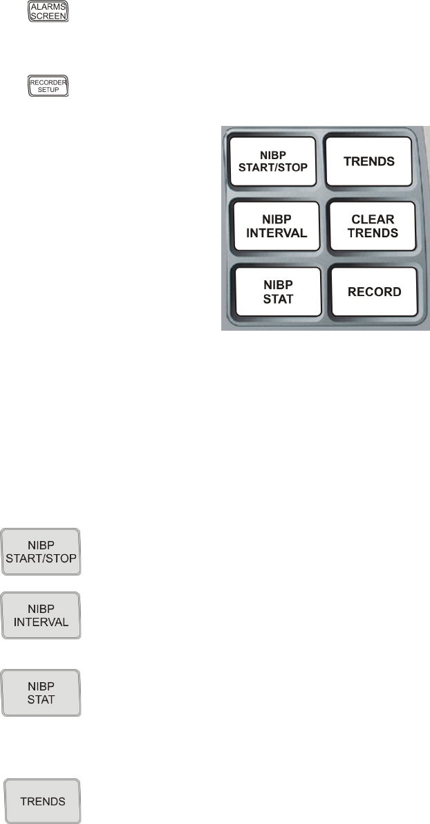
Figure 1-4. The Middle Keypad Set
c. The Middle Keypad Set. (See Figure 1-4) The middle keypad set contains six push
keys. The three on the left provide control of the NIBP monitoring feature with two of
the keys (NIBP START/STOP and NIBP STAT) providing direct control of NIBP
measurements and the third (NIBP INTERVAL) bringing up a menu that allows
adjustment of the NIBP auto mode interval feature. On the right side of this set are two
keys which control the Trending feature of the monitor (TRENDS and CLEAR
TRENDS) while a third (RECORD) provides a hardcopy printout of selected
parameters as specified by operator adjustments in the RECORDER Menu. The six
push keys are described below:
(5) ALARMS SCREEN. The ALARMS SCREEN key is a dual function key
that allows the operator to setup the Alarms monitoring feature. When the
monitor display is in the Normal Screen and the ALARMS SCREEN key is
pressed, the Main Alarm Setup Screen will appear; when the monitor display
has any icon highlighted and the ALARMS SCREEN key is pressed, an
Alarm Setup Screen for the highlighted parameter appears.
(6) RECORDER SETUP. The RECORDER SETUP key allows the operator
to setup the Recorder option.
(1) NIBP START/STOP. This key starts a new NIBP measurement, or stops a
measurement that is already in progress..
(2) NIBP INTERVAL. Pressing the NIBP INTERVAL key brings up the NIBP
INTERVAL Menu where the cycle time (time between readings) of the NIBP
Automatic Reading Mode may be adjusted.
(3) NIBP STAT. This key starts the NIBP STAT Mode measurements. This
mode may be terminated by depressing the NIBP START/STOP key. The
STAT Mode performs up to five (5) NIBP measurements in rapid succession
(with a short pause between readings) within a maximum time frame of five
(5) minutes.
(4) TRENDS. The TRENDS key allows the operator to setup the Trend
monitoring feature. The exact operation of the TRENDS key is based on
whether or not a feature is currently highlighted. If a feature is currently
highlighted, pressing the TRENDS key will bring up a Trend which is specific
to the highlighted feature; if a feature is not currently highlighted, pressing the
TRENDS key will bring up the HISTORY Menu and Tabular Display (See
Section 5).
1-6
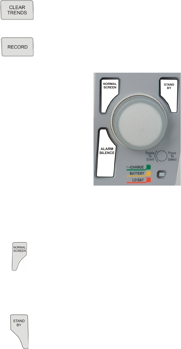
Figure 1-5. The Bottom Keypad Set
d. The Bottom Keypad Set. (See Figure 1-5) The bottom keypad set is not grouped like
the top and middle, but are grouped around the Rotary Knob. There are three push keys
in this set (NORMAL SCREEN, STANDBY and ALARM SILENCE) which
provide direct control of operational features of the monitor. The three push keys are
described below.
(5) CLEAR TRENDS. Pressing the CLEAR TRENDS key allows the operator
to clear all the stored data from memory. To prevent accidental erasure of
patient data, there is a Yes/No box associated with this key that appears to
ensure that the operator meant to clear the trend data.
(6) RECORD. Pressing this key records the Single Trace or Dual Trace selections
(as specified by operator adjustments made in the RECORDER Menu).
The recorder stops automatically after approximately 30 seconds, or when the
RECORD key is pressed again; in either case, the printout ends with a “Snap
Shot” of the active patient parameter data.
(1) NORMAL SCREEN. Pressing the NORMAL SCREEN key returns the
3160 MRI Physiological Monitoring System from any menu to the normal
screen.
(2) STANDBY. Pressing the STANDBY key places the 3160 MRI
Physiological Monitoring System into the Standby Mode. The monitor stays
in Standby Mode until the STANDBY key is pressed a second time. Except
for the three (3) key features given below, the monitor operates normally by
continuing to provide current patient information on the Display Screen.
While in Standby Mode:
• All audible alarms and nurse call are disabled. The disabled alarms
are indicated on the screen by the “X” through the bell shaped
Alarm Status Symbol.
• Active NIBP automatic measurements and STAT Mode
measurements are suspended.
• No automatic printout is generated.
• Default NIBP inflation pressures will be used for all manual NIBP
readings.

1-7
(a) Alarm Silenced. Any new alarm conditions will cause the Alarm to
reactivate and will also activate the Nurse Call Alarm.
In addition, while alarms are silenced the following conditions
apply:
•Unlatched Alarms. If the alarm system has been set to
UNLATCHED in the ALARMS Menu and an Alarm Limit
is violated, pressing the ALARM SILENCE key will
silence the Alarm Tone turns off the Nurse Call Alarm and
puts the letter “S” in the Alarm Bell when an active Alarm
Limit has been violated. While the parameter continues to
violate its limits, the numerics of the violating parameter
continue to flash on the screen.
•Latched Alarms. If the alarm system has been set to
LATCHED in the ALARMS Menu and an Alarm Limit is
violated, while the parameter continues to violate its limits,
pressing ALARM SILENCE key stops the Alarm Tone,
but the numerics remain red and continue to flash, even
after the parameter returns to within its Alarm Limits.
•ALARM HOLD. If the ALARM SILENCE key is pressed
when the Alarm Tone is enabled but no alarm condition
currently exists, a “SOUND ON HOLD” message appears
in the upper center of the screen with a count down timer
starting at 180 (counting down at a 1 second rate) denoting
that the Alarm Tone is being temporarily held silent. In
addition, an “H” will appear in the Alarm Status Symbol to
further alert the operator that the Alarm System is on Hold.
If the Alarm Tone is sounding, the first pressing of the
ALARM SILENCE key stops the Alarm Tone, turns off
the Nurse Call Alarm, and puts the letter “S” in the Alarm
Bell, and a second pressing enables Alarm Hold.
The monitor automatically exits alarm hold after three
minutes, and the “SOUND ON HOLD” message
disappears from the screen, reactivating the Alarm Tone
(remember that a current alarm condition, which has been
silenced, will not sound again unless the condition returns
within limits and then violates the limit again. Also
remember that a silenced alarm may not be accompanied by
the Alarm Silence message). Pressing the ALARM
SILENCE key before the three minute period is over will
also reactivate the Alarm Tone and nurse call alarm and
remove the “SOUND ON HOLD” message from the
screen.
(3) Alarm Silence Key. Pressing the ALARM SILENCE key, when the audible
alarms are enabled (as denoted by the absence of the “X” through the bell
shaped Alarm Status Symbol), will affect the monitor as described below:
WARNING
An active silenced alarm may not be accompanied by an Alarm Silence message or an “S” in the
Alarm Bell icon if the Alarm Hold sequence has been activated, or if a subsequent additional alarm
has occurred and self-corrected.
1-8
The user is able to put alarms on hold (SOUND ON
HOLD) only when the Alarm Tone is active (no X appears
in the bell symbol in the upper left of the screen). Alarm
Hold is useful for temporarily disabling the Alarm Tone.
This might be useful, for example, when changing ECG
leads or for any user activity which might cause a “false”
alarm.
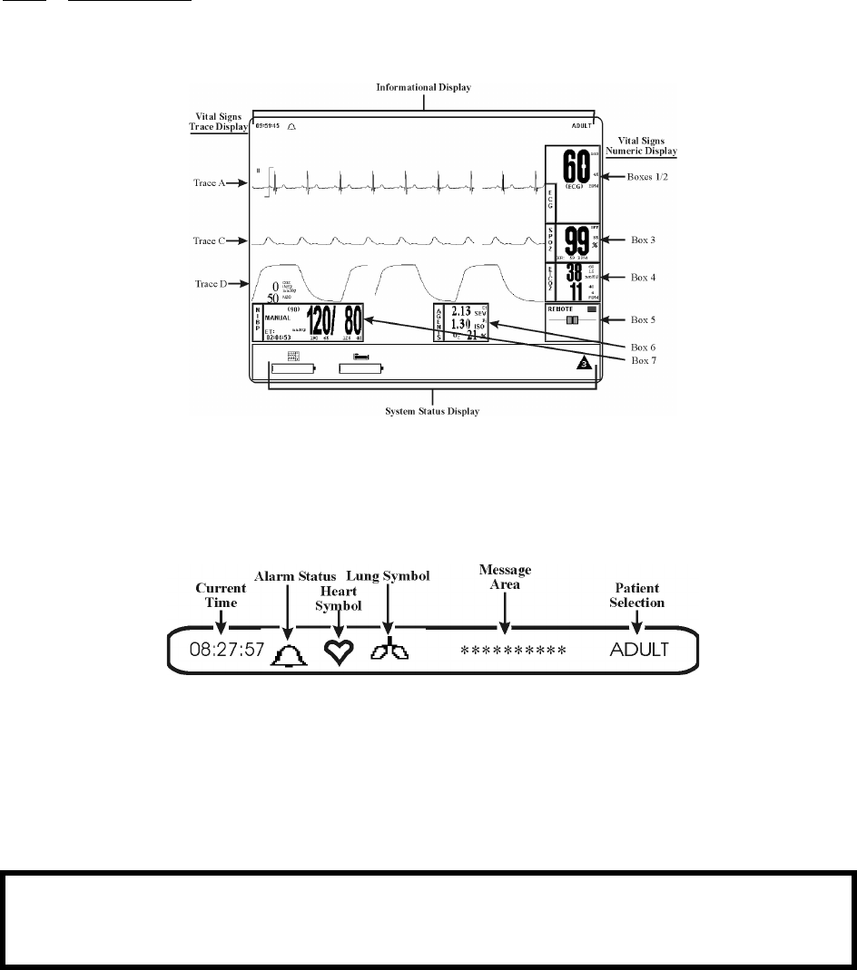
1.4.2 DCU Display. The DCU display screen (See Figure 1-6) displays four groups of data: 1) the
Informational Display, 2) the Vital Signs Trace Display, 3) the Vital Signs Numeric Display and 4) the
Status Display. The entire display screen, with its four different display groups, is called the “Normal
Screen.” The four display areas are described below.
Figure 1-6. The Normal Screen
a. Informational Display. (See Figure 1-7) The Informational Display is located at the
top of the Normal Display. This display provides the operator with the current time, the
Alarm Status Bell Symbol, a flashing Heart Rate Symbol, a flashing Lung Symbol, any
current user messages and the current Patient Selection.
Figure 1-7. The Informational Display
(1) Time. The current time is displayed in a 12 or 24 hour format (hh:mm:ss). The
time, date and clock mode (12 or 24 hour) is adjusted in the TIME Menu.
(2) Alarm Status Symbol. The 3160 MRI Physiological Monitoring System
sounds an Alarm Tone when any monitored parameter violates its
programmed Alarm Limits. The status of the Alarm Tone is indicated by the
bell shaped Alarm Status Symbol.
WARNING
When an “X” appears in the Alarm Status Symbol, the audible Alarm Tone will NOT sound for any
reason.
1-9
(a) The letter “H” appearing in the bell indicates that the alarms have been
placed on temporary Hold with the ALARM SILENCE key.
Similarly, during power-up the “SOUND ON HOLD” message
displayed in the center of the screen indicates that the Alarm Tone is
temporarily placed on hold. A 180 second countdown timer is also
displayed under the message.
(b) The letter “X” appearing in the bell symbol indicates that the alarms
have been turned off from the ALARMS Menu or that Standby Mode
has been engaged. In this case the Alarm Tone will not sound for any
reason.
(c) The letter “S” appearing in the bell indicates that a current alarm has
been silenced with the ALARM SILENCE key. This feature will
disable only the alarms that were current when the ALARM
SILENCE key was pressed, any new alarms will cause the Alarm
Tone to sound.
(3) Heart Symbol. The Heart Symbol flashes on the screen each time a heart beat
is detected. A tone is sounded at the same time (unless turned off in the ECG
Menu or the SPO2 Menu).
(4) Lung Symbol. The Lung Symbol flashes on the screen at the end of each
detected breath whenever the EtCO2 monitoring feature is turned on (if
available).
(5) Messages. These messages assist the operator in various aspects of the
operation of this monitor.
(6) Patient Selection. Indicates the selected patient (ADULT or NEONATAL) for
the ECG and NIBP monitoring features.
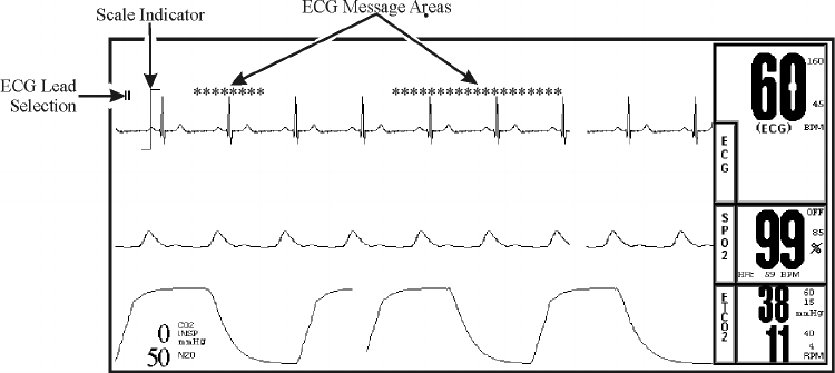
Figure 1-8. The Vital Signs Trace Display
b. Vital Signs Trace Display. (See Figure 1-8) The Vital Signs Trace Display is located
in the middle of the Display Screen. This Display provides the operator with a trace of
the selected parameters and also contains Numerical Vital Sign indications for the
selected patient parameter.
(1) The Vital Signs Trace Display portion of the screen is divided into six separate
trace areas. When turned on, the traces are fixed on the screen and updated with
an Erase Bar. When a trace has been turned off, that portion of the screen is
blank. The numeric values for each trace appear near the right screen
boundary.
(2) If the value is greater than or equal to a maximum calculable value, “OVR”
(Over Range) is alternately displayed with the numeric value.

1-10
(3) TRACE A, C and D are assigned according to parameter and come on/go off
as parameters are turned on or off. Trace B is the location used for the
“Freezing” of a waveform and is not assigned a parameter.
The following is a description of each Trace:
(4) TRACE A. The ECG trace is displayed in this position, unless turned off from
either the ECG Menu or the SETUPS Menu. The main menu for this trace and
for the Heart Rate are brought up with the selection of the ECG Menu-Select
Icon.
(a) The heart rate is displayed near the right screen boundary in the Trace
A position. The numerics turn Red and flash if a Heart Rate Alarm
Limit is violated. The color of the numerics is that of the selected HR
source.
(b) The annotation below the heart rate value indicates the source of the
heart rate, as selected from the ECG Menu, the NIBP Menu and the
SPO2 Menu. Heart rate source choices are AUTO, ECG, SPO2 and
NIBP (there is an ART option shown but selecting this item will bring
up a message alerting the operator that the option is not available).
(c) A red flashing numeric value on the screen indicates that an alarm for
this value has been violated. This provides a visual indication of alarm
violations, even when the Alarm Tone is turned off.
(d) If AUTO is selected as the HR SOURCE, the highest-priority active
input is utilized for displaying the heart rate, in the order listed above.
The ECG trace must be off, or lead fail present, for the Auto source not
to be the ECG trace.
(e) If the monitor does not find a valid heart rate source when set to
AUTO and NIBP is OFF, the heart rate is annotated with “NONE.”
(f) The displayed lead for the ECG 1 is indicated near the left screen
boundary.
(g) A scale indicator is displayed near the left screen boundary in the ECG
waveform area(s). It represents a 1mV amplitude in the currently
selected scale.
(5) TRACE B. Trace B displays a frozen waveform for detailed analysis.
(6) TRACE C. Trace C displays the SpO2 waveform (if SpO2 enabled).
(7) TRACE D. Trace D displays the Respiration waveform (if EtCO2 enabled).
Figure 1-9. The Vital Signs Numeric Display
c. Vital Signs Numeric Display. (See Figure 1-9) The Vital Signs Numeric Display is
located at the bottom and right of the display screen. This Display is divided with
boxes that provide the operator with numerical indications for NIBP and Agents.
1-11
The following is a description of the NIBP and Agents boxes.
(1) Non-Invasive Blood Pressure (NIBP). NIBP is the first parameter (from the
left) displayed in the Vital Signs Display. The Systolic, Diastolic and Mean
blood pressure values are displayed along with measurement information such
as the Elapsed Time (ET) since the last measurement and the time until the
next measurement (if in the Automatic Mode). While in the Manual mode,
MANUAL is shown in the place of the time until the next measurement.
During a reading cycle the current cuff pressure is displayed (“CUFF: XXX”).
Between the measurements the elapsed time (time since the last reading) is
displayed (ET= 00:00:00) instead of the cuff pressure.
The NIBP error messages are shown in place of the “NEXT: 00:00:00.” If
errors are detected by the NIBP circuitry, one of the following messages are
displayed which preclude the determination of the blood pressure:
(a) OVER PRES: Cuff inflation pressure has exceeded 280 ±5 mmHg.
(b) CALIB: Monitor has detected DC offset below 1 mmHg or above 11
mmHg.
(c) NOT INFLATING: Cuff inflation runs longer than 30 seconds.
(d) LONG PRES: Cuff pressure remains at one level for more then 30
seconds.
(e) CUFF LEAK: The cuff inflation pump has run for more than 20
seconds. Check hose and cuff connections.
(f) RESID PRES: Cuff pressure above 20 mmHg for more then 180
seconds.
(g) WRONG CUFF: The wrong cuff is attached for the patient setting.
Select Adult or Neo (as appropriate) in the SETUPS Menu.
(2) Agents. The Agents box is in the middle of the Normal Screen. This box
displays the numerical values for a wide variety of anesthetic agents. Most
Anesthetic Agents are identified and specified by name next to the numerical
value for the gas being measured.
d. System Status Display. The System Status Display is located at the very bottom of the
Normal Display and provides the operator with visual indications of the operational
status of the system. From left to right the symbols are the DCU Battery Status symbol,
the WPU Communication/ Battery Status symbol and the Network symbol.
(1) DCU Battery Status. This symbol is currently inactive. In the future it will
provide a visual indication of the DCU Battery Charge Status.
(2) WPU Communication/Battery Status Symbol. This symbol is currently
only partially active. In the future it will indicate the Battery Status of the
WPU. Currently it indicates the status of the communication link between the
DCU and WPU by replacing the normal symbol of the Bed and Battery with
one of the Bed boxed in red with a red X through it.
(3) Network Symbol. This symbol provides the Network Designation for the
wireless link. It is important that networked units are correctly identified to
avoid the unintentional interference with a patient on another network of
monitors. This symbol aids the identification of the selected network by
providing three different indications with shapes, colors and numbering all
used to identify specific networks.

1-12
e. Front Panel Power Light. (See Figure 1-5) The Front Panel Power Light (located
beneath the Rotary Knob) is a three color LED that indicates the AC/Battery Power
condition of the monitor. The Power Light will illuminate Green, Yellow and Red as
described below:
(1) Green Light. A Green Light indicates that the monitor is connected to AC
Line Power and that the internal battery circuitry is operational. In normal
operation, this light will be illuminated Green.
(2) Yellow Light. A Yellow Light indicates Caution because the monitor is
operating on the internal batteries.
(3) Red Light. A Red Light indicates Warning because monitor shutdown is soon
to occur. The internal batteries have fallen below the required operational
output and an AC Wall Outlet should be located, and the monitor plugged into
it through the AC Power Adapter, immediately.
f. Yes/No Menu. In various menus, the operator may accidentally make a selection that
has significant irreversible effects (e.g.: erasing patient data). To protect against such
accidents a Ye s / N o Menu is associated with these selections. This menu has only two
active selections: YES and NO. The operator must select one of the two choices to
either confirm the change to take place, or to cancel it. A delay of approximately 30
seconds without any selection is equivalent to selecting NO. The Ye s / N o Menu is
removed upon operator selection, at the end of the time-out feature, by pressing the
NORMAL SCREEN button or by pressing the STANDBY button.
1.5 Cleaning. The monitor is not sterilizable. Never immerse the unit in any fluid or attempt to
clean it with liquid cleaning agents. Remove dirt and dust from the monitor by wiping it with a soft,
damp cloth.
Stains can be removed from the case by scrubbing it briskly with a damp cloth. Unplug the
monitor and remove the batteries before cleaning. Do not permit liquid to contact the front or rear
of the monitor, or permit liquid to drip into the printer or cooling slots. Allow the unit to dry
completely before returning it to operation.
1.5.1 Cleaning Accessories. Any reusable patient accessories should be cleaned after each use.
Disposable patient accessories should be discarded and replaced with new items.
To clean reusable accessories, first, remove the accessory from use. Remove any dirt or debris
using soap and water. Avoid immersing accessory in any fluid for cleaning.
Inspect the accessory for any cracks, holes, tears, cuts, etc., that could affect operation, and
replace as necessary.
If disinfection is required, use only the recommended liquid surface disinfectants, unless
otherwise specified in the accessories listing. Recommended surface disinfectants include dilute
solutions of either quaternary ammonium compounds, iodophors or gluteraldehydes.
WARNING
Electrical shock hazard: Turn off Monitor and disconnect from AC Power before cleaning. Do not
immerse the monitor in any water or liquid for any reason. Do not apply excessive pressure to the
monitor display screen.

2-1
SECTION 2
INSTALLATION
2.0 INSTALLATION
2.1 Introduction.
2.2 Monitor Installation. Remove the monitor from the shipping carton and examine for any
damage which may have occurred during shipment. Check all materials against the packing list and
purchase request. Save all packing materials, invoice and bill of lading as these may be required to
process a claim with the carrier if damage during shipment occurred. Contact Invivo Customer Service
for prompt assistance in resolving shipping problems.
2.2.1 Monitor Mounting. .
a. Site Selection. Select a location where the monitor will not come in contact with
liquids and where the heat will not raise the monitor's temperature above 44°C.
Maintain adequate air flow around the unit to help keep it within the normal operating
temperature range. Also, there are air holes on the bottom and rear of the monitor that
must not become clogged or closed off. Humidity and temperature must never
combine to cause condensation to form in or on this monitor.
2.2.2 Preparing the 3160 MRI Physiological Monitoring System for Use. Perform the following
steps to prepare the monitor for use:
a. Ensure that you have read the Precautions and User Responsibility sections of this
manual. This provides important safety information.
b. Ensure that there are no cracks in the monitor case or display.
c. Ensure that all patient connections are intact.
d. Ensure that all patient cables meet manufacturers recommended condition for patient
use. Visually inspect for breaks, cracks and/or fraying.
e. Report any problems to Invivo, or an authorized Invivo Service Representative.
f. Verify the accuracy and proper functioning before using the monitor on a patient.
Never use a monitor that is suspected of being inaccurate or out of calibration.
2.2.3 Monitor Start Up. Perform the following steps to bring the monitor on line for use:
a. Connect the Power Cord to the A/C Power Cord Connection plug on the monitor back
panel.
b. Ensure that the Panel Power Switch is set to the OFF position.
c. Install the sealed batteries.
d. Plug the Power Cord into an appropriate facility power source.
e. Set the Power Switch to the ON position
f. It is recommended to allow the batteries to charge a minimum of 8 hours before
utilizing the monitor for battery use. For normal use the monitor should be plugged into
an AC electrical outlet through the AC Power Adapter and not on battery power.
CAUTION
Two separate AS201 AC Power Adapters should never be plugged into the WPU and DCU units at
the same time. Failure to comply can result in a power overload conditin and cause serious damage
to themonitor’s internal circuits.
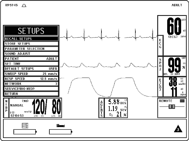
3-1
SECTION 3
PREPARATION FOR USE
3.0 PREPARATION FOR USE.
3.1 Introduction. This monitor provides the operator with the ability to store and recall different
system configurations, select and display the available parameters, select special system functions, set
the date and time and select test menus. Access to this wide array of features is available through the
SETUPS Menu which is accessed by pressing the SETUP Menu-Select Key.
3.2 SETUPS Menu. (See Figure 3-1) On the DCU, pressing the SETUP Menu-Select key
brings up the SETUPS Menu; on the WPU, attach an external monitor and keyboard then select the
SETUP Menu-Select key. From this menu, the operator has the ability to fine tune the operation of the
3160 MRI Physiological Monitoring System to suit individual situations.
a. DCU SETUPS Menu. While in the DCU SETUPS Menu, individual setup
configurations may be saved and recalled, the available parameters may be turned off
and on, the monitor sounds may be adjusted, the patient mode may be switched
between adult and neonate, the date and time may be adjusted, the network designation
may be set, the monitor may be set to default to the Factory or a User configuration. In
addition to control over these features, this menu allows the sweep speed and
respiration speed to be selected. This menu has a time-out feature. If no action is taken
for approximately 60 seconds, the monitor will automatically return to the Normal
Screen.
Figure 3-1. The DCU SETUPS Menu
NOTE
If a particular parameter is not installed, it can not be set to ON. Once the monitor is configured for a
particular procedure or user, the store and recall feature can be used to instantly reset the monitor.
The SETUPS Menu is different from the DCU to WPU due to the different operational
requirements of the separate units that comprise the 3160 MRI Physiological Monitoring System.
Paragraph 3.2 will first discuss what is common between the two then divide into unique sections to
cover the differences between the DCU and WPU Setups Menu.
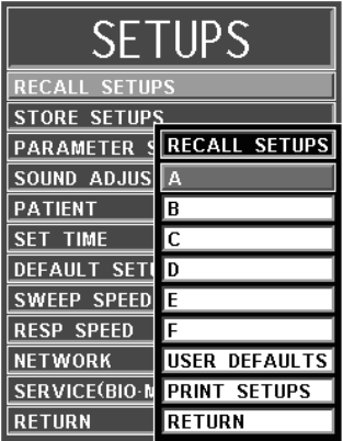
3-2
The following is a description of the operation of the DCU SETUPS Menu options:
(1) Recall Setups. To select this menu option, turn the Rotary Knob until the
RECALL SETUPS option is highlighted, then press the Rotary Knob to
select. Selecting this menu option will bring up the RECALL SETUPS
submenu and allow the operator to Recall a previously stored Monitor Setup
(See Figure 3-2). This menu has a time-out feature. If no action is taken for
approximately 60 seconds, the monitor will automatically return to the
Normal Screen.
Figure 3-2. The RECALL SETUPS Menu
The following is a description of the RECALL SETUPS Menu options:
(a) A. To select this menu option, turn the Rotary Knob until A is
highlighted, then press the Rotary Knob to select. Selecting this menu
option brings up a Yes/No confirmation menu and, upon confirmation,
will recall the setups for the monitor from the Memory Block A.
(b) B. Except for using the Memory Block B, this menu option is identical
in function to menu option A.
(c) C. Except for using the Memory Block C, this menu option is identical
in function to menu option A.
(d) D. Except for using the Memory Block D, this menu option is identical
in function to menu option A.
(e) E. Except for using the Memory Block E, this menu option is identical
in function to menu option A.
(f) F. Except for using the Memory Block F, this menu option is identical
in function to menu option A.
(g) USER DEFAULTS. Selecting this menu option recalls the setups for
the monitor from the USER DEFAULTS memory block. If no User
Defaults have been set, this selection will Recall the Factory Defaults.
If the DEFAULT SETUPS is set to USER in the SETUPS Menu,
the monitor will automatically recall the setups stored in this
memory block for new patients upon monitor power-up.
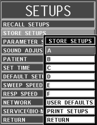
3-3
(h) PRINT SETUPS. To select this menu option, turn the Rotary Knob
until PRINT SETUPS is highlighted, then press the Rotary Knob to
select. Selecting this menu option brings up the PRINT SETUPS
Menu, which provides a selection of system setups to print.
(i) RETURN. Selecting this menu option returns the monitor to the
Normal Screen.
(2) Store Setups. To select this menu option, turn the Rotary Knob until the
STORE SETUPS option is highlighted, then press the Rotary Knob to select.
Selecting this menu option will bring up the STORE SETUPS Menu and
allow the operator to Store up to seven (7) sets of Monitor Setups for future
Recall (See Figure 3-3). This menu has a time-out feature. If no action is
taken for approximately 60 seconds, the monitor will automatically return to
the Normal Screen
Figure 3-3. The STORE SETUPS Menu
The following is a description of the STORE SETUPS Menu options:
(a) A. Selecting this menu option will store all setups for the monitor in the
storage Memory Block A.
(b) B. Except for using the Memory Block B, this menu option is identical
in function to menu option A.
(c) C. Except for using the Memory Block C, this menu option is identical
in function to menu option A.
(d) D. Except for using the Memory Block D, this menu option is identical
in function to menu option A.
(e) E. Except for using the Memory Block E, this menu option is identical
in function to menu option A.
(f) F. Except for using the Memory Block F, this menu option is identical
in function to menu option A.
(g) USER DEFAULTS. Selecting this menu option will store all setups
for the monitor in the storage Memory Block USER DEFAULTS.
If the DEFAULT SETUPS is set to USER in the SETUPS Menu,
the monitor will automatically recall the setups stored by this menu
option for new patients upon warm start.
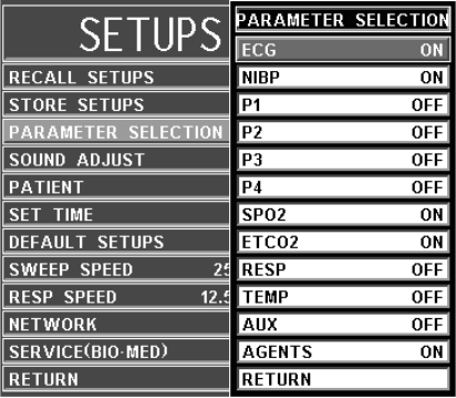
3-4
(h) PRINT SETUPS. Selecting this menu option brings up the PRINT
SETUPS Menu which provides a selection of system setups to print.
(i) RETURN. Selecting this menu option returns the monitor to the
Normal Screen.
(3) Parameter Selection. To select this menu option, turn the Rotary Knob until
the PARAMETER SELECTION option is highlighted, then press the Rotary
Knob to select. Selecting this menu option will bring up the PARAMETERS
SELECTION Menu (See Figure 3-4).
Figure 3-4. The PARAMETER SELECTION Menu
Selection of this menu allows the operator to turn various parameters ON and
OFF. If the parameter selected is not installed, attempting to turn it ON will
cause the message “XXX IS NOT ENABLED” to be displayed. If the Freeze
feature is enabled, changes to parameter selections are not allowed; if Freeze is
enabled, the monitor displays a WARNING Box that alerts the operator that
this menu may not be accessed.
The following is a description of the PARAMETERS SELECTION Menu
options:
(a) ECG. Selecting this menu option will turn the ECG display ON
(default) or OFF. The heart rate will remain on the screen, allowing it to
be displayed from another source, if the heart-rate source (the HR
SOURCE selection) is set to AUTO.
(b) NIBP. Selecting this menu option switches the NIBP ON (default) and
OFF.
(c) P1. This option is not available on the 3160 MRI Physiological
Monitoring System.
(d) P2. This option is not available on the 3160 MRI Physiological
Monitoring System.
(e) P3. This option is not available on the 3160 MRI Physiological
Monitoring System.
(f) P4. This option is not available on the 3160 MRI Physiological
Monitoring System.
(g) SPO2. Selecting this menu option switches SpO2 ON and OFF.
(h) EtCO2. Selecting this menu option switches EtCO2 ON and OFF.
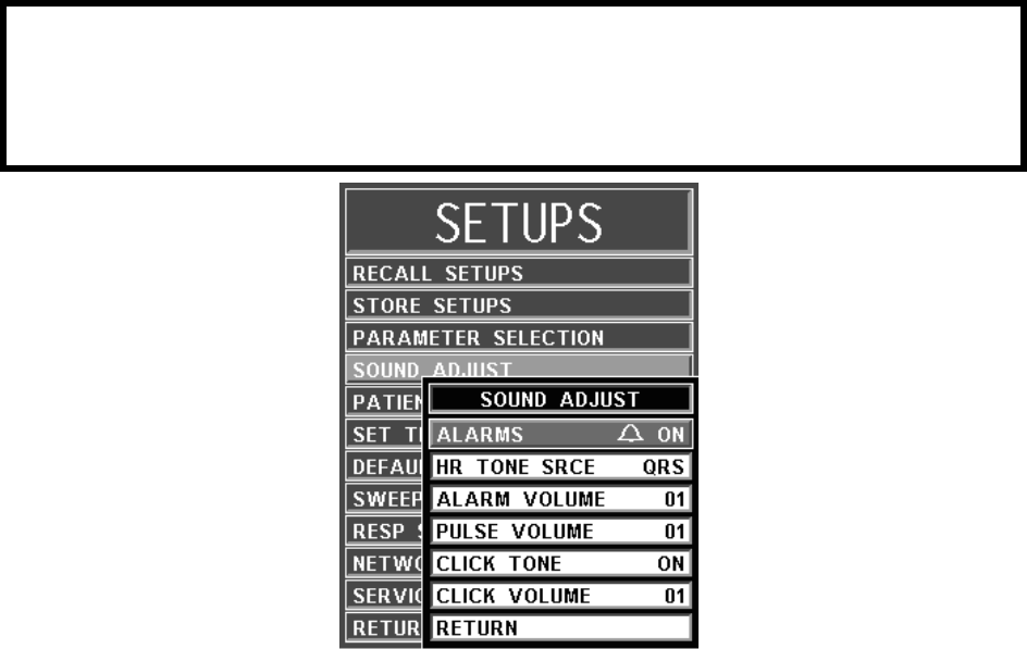
3-5
(i) RESP. This option is not available on the 3160 MRI Physiological
Monitoring System.
(j) TEMP. This option is not available on the 3160 MRI Physiological
Monitoring System.
(k) AUX. This option is not available on the 3160 MRI Physiological
Monitoring System.
(l) AGENTS. (If option is installed) Selecting this menu option switches
the Anesthetic Agent Option ON and OFF (default).
(m) RETURN. Selecting this menu option returns the monitor to the
Normal Screen.
(4) Sound Adjust. Selecting this menu option will bring up the SOUND
ADJUST Menu (See Figure 3-5) which allows the user to switch the Alarm
Tone ON and OFF, set the heart-rate tone source and set the volume for the
different sounds the 3160 MRI Physiological Monitoring System produces.
While in this menu, all real tones are disabled and the message “REAL
TONES DISABLED” is displayed at the top of the screen. Note that only the
sound is disabled and the violated alarms will still flash on the screen if the
parameter's Alarm Limit is violated. This menu has a time-out feature. If no
action is taken for approximately 60 seconds, the monitor will automatically
return to the Normal Screen.
Figure 3-5. The SOUND ADJUST Menu
The following is a description of this menu's options:
(a) ALARMS. Selecting this menu option will turn the alarm sound ON
and OFF. When turned off, an “X” appears in the bell symbol on the
screen, and on the one in the menu option area, indicating that the
alarm sound has been disabled. This menu option is identical to, and
interactive with, the SOUND menu option in the ALARMS Menu.
WARNING
The Alarm Tone can be set to OFF. Always check that the Alarm Tone setting is appropriate for each
particular patient. Alarm Sound volume is adjustable for suitability to various clinical environments
(where background noise may range from relatively quiet to noisy). Always verify that the user/
attendant of this monitor can hear the Alarm Sound above the ambient noise.
3-6
(b) HR TONE SRCE. Selecting this menu option will select the heart rate
tone source. The options are OFF (default), QRS and SPO2. When
source is QRS, the tone sounds at the detection of QRS from the ECG
parameter. When source is SpO2, the tone sounds at the detection of the
pulse from the Pulse Oximeter parameter.
The pulse tone is modulated by the SpO2 value. The lower the
SpO2 value the lower the pitch of the pulse tone will be.
This menu option is identical to, and interactive with, the HR
TONE SOURCE Menu option in the ECG and SPO2 Menus.
(c) ALARM VOLUME. Selecting this menu option allows the selection
of volume for the Alarm Tone. The range is 1 - 10 (default is 4).
The 3160 Patient Monitoring System generates the Alarm Tone
(while in the VOLUME Menu) to provide the user with an audible
indication of the current volume-level setting.
(d) PULSE VOLUME. Selecting this menu option allows the selection of
volume for the pulse tone. The range is 1 - 10 (default is 4).
The 3160 Patient Monitoring System generates the pulse tone
(while in the VOLUME Menu) to provide the user with an audible
indication of the current volume-level setting.
(e) CLICK TONE. Selecting this menu option turns the click tone
generation of the device ON and OFF without affecting the adjusted
volume for the click tone.
(f) CLICK VOLUME. Selecting this menu option allows the selection of
volume for the click tone. The range is 1 - 10 (default is 4).
The 3160 Patient Monitor generates the click tone (while in the
VOLUME Menu) to provide the user with an audible indication of
the current volume-level setting.
(g) RETURN. Selecting this menu option returns the monitor to the
Normal Screen.
(5) Patient. Selecting this menu option determines the Adult (default) or the
Neonatal Mode for the operation of the ECG and NIBP parameters.
(a) ADULT. The initial NIBP inflation pressure is 170 mmHg. The
maximum inflation pressure is 285 mmHg. Also, the adult NIBP
pre-amplifier and the adult NIBP algorithm are used. ECG Heart Rate
detection sensitivity is 200 µV minimum.
(b) NEONATE. The initial inflation pressure is 120 mmHg. The
maximum inflation pressure is 150 mmHg. Also, the neonatal NIBP
pre-amplifier and the neonatal NIBP algorithm are used. ECG Heart
Rate detection sensitivity is 100 µV minimum.
(6) Set Time. Selecting this menu option will bring up the SET TIME Menu (See
Figure 3-6). From the SET TIME Menu the time and date may be set. The
time is displayed in the upper left corner of the screen. The clock continues to
operate when the power is off. The date format is MMM DD, YYYY (e.g., Jan
01, 2001). When a hard copy printout is made, the time and date is printed on
the edge of the printout.
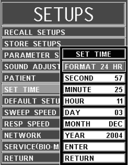
3-7
Figure 3-6. The SET TIME Menu
The following is a description of the operation of the SET TIME Menu options:
(a) FORMAT. Selecting this menu option switches the format of the time
display between 12 hour and 24 hour.
(b) SECOND. Selecting this menu option allows scrolling through
seconds.
(c) MINUTE. Selecting this menu option allows scrolling through
minutes.
(d) HOUR. Selecting this menu option allows scrolling through hours.
(e) DAY. Selecting this menu option allows scrolling through days.
(f) MONTH. Selecting this menu option allows scrolling through months.
(g) YEAR. Selecting this menu option allows scrolling through years.
(h) ENTER. Selecting this menu option enters the newly-selected time
and date when all changes are completed.
Pressing ENTER after the new time and date are completely set
puts the newly set time and date into effect. Otherwise, the old time
is restored upon exiting the SET TIME Menu.
(i) RETURN. Selecting this menu options returns the monitor to the
Normal Screen.
(7) Default Setups. Selecting this menu option will switch the power-on defaults
between FACTORY and USER modes. If set to FACTORY, the monitor will
power up with the entire system reset to factory default values. If set to USER,
the monitor will power up and automatically recall the user defaults from
memory.
(8) Sweep Speed. Selecting this menu option will bring up the SWEEP SPEED
Menu. The SWEEP SPEED Menu allows the operator to switch the recorder
and the screen trace speed between 25 and 50 mm/second. This menu option is
identical to, and interactive with, the SWEEP SPEED menu option in
RECORDER Menu.
NOTE
No new window is provided for the following selections. The setting to be adjusted becomes
highlighted within the existing menu.
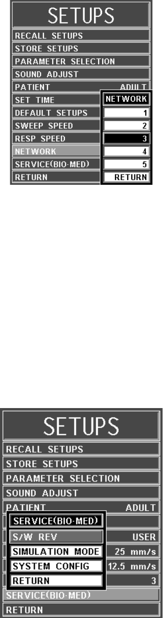
3-8
(9) Respiration Speed. Selecting this menu option will bring up the RESP
SPEED Menu. The RESP SPEED Menu allows the operator to set the
Respiration Speed at the following predetermined levels: 25 mm/s, 12.5 mm/s,
6.25 mm/s, 3.125 mm/s, 1.5625 mm/s and 0.33333 mm/s.
Figure 3-7. NETWORK Menu
(10) Network. Selecting this menu option brings up the NETWORK Menu. The
NETWORK Menu (See Figure 3-7) allow the operator to set the network
designation of the monitor. This designation must match between the DCU and
WPU for the two units to communicate. This menu option is identical to, and
interactive with, the NETWORK option in the System Configuration Menu.
(11) Service (Bio-Med). Selecting this menu option will bring up the SERVICE
(BIO-MED) Menu (See Figure 3-8). The DCU SERVICE (BIO-MED) Menu
provides the operator with the ability to identify the Software Revision level,
place the system into a Simulation Mode (used for training purposes only) and
adjust the configuration of the system.
Figure 3-8. The DCU SERVICE (BIO-MED) Menu
NOTE
The SERVICE (BIO-MED) Menu should only be used by qualified service personnel thoroughly
familiar with the operation and service of this monitor.
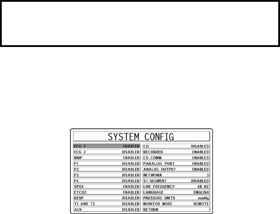
3-9
The following is a description of the options available in the SERVICE
(BIO-MED) Menu:
(a) S/W REV. Selecting this menu item brings up another window which
contains detailed inforation about the operating software of the DCU.
This window contains the revision level and date of build along with
other technical information concerning the DCU software. To exit this
window, the operator either selects the OK button on the window or the
NORMAL SCREEN key on the monitor front panel.
(b) SIMULATION MODE. This menu option allows the operator to turn
the Simulation Mode ON. When selected the monitor will first display
a YES/NO Menu and require user confirmation before entering the
Simulation Mode. While in the Simulation Mode the displayed patient
information is computer generated and not actual patient
determinations. As a safety feature, while in the Simulation Mode the
message “SIMULATION” is displayed in the center of the screen and,
when printing any strip or chart, “SIMULATION” will appear on the
printout. To exit the Simulation Mode, the monitor must be powered
Off.
Figure 3-9. The SYSTEM CONFIG Menu
(c) SYSTEM CONFIG. The SYSTEM CONFIG Menu (See Figure 3-
9) is brought up by selecting the SYSTEM CONFIG Menu option.
Most of the options in this menu are sensitive and are, as a result,
protected by a five (5) digit password that must be entered before the
option may be adjusted. The Language, Pressure Unit and Network
options are the only options in this menu which do not require that the
service code be entered.
The following options are available in this menu:
•ECG 1: Selecting this menu option will enable/disable the
ECG 1 module.
•ECG 2: This option is not available on the 3160 MRI
Physiological Monitoring System.
•NIBP: Selecting this menu option will enable/ disable the
NIBP module.
WARNING
The Simulation Mode will display real looking waveforms which are computer generated. The
monitor will not monitor patients while in the Simulation Mode. Do not activate the Simulation
Mode when this monitor is connected to a patient. To exit the Simulation Mode, the monitor must
be powered Off.
3-10
•P1: This option is not available on the 3160 MRI
Physiological Monitoring System.
•P2: This option is not available on the 3160 MRI
Physiological Monitoring System.
•P3: This option is not available on the 3160 MRI
Physiological Monitoring System.
•P4: This option is not available on the 3160 MRI
Physiological Monitoring System.
•SPO2: Selecting this menu option will enable/disable the
SpO2 module.
•EtCO2: Selecting this menu option will enable/disable the
EtCO2 module (if installed).
•RESP: This option is not available on the 3160 MRI
Physiological Monitoring System.
•TEMP 1 AND 2: This option is not available on the 3160
MRI Physiological Monitoring System.
•AUX: This option is not available on the 3160 MRI
Physiological Monitoring System.
•CO: This option is for future service enhancement.
•RECORDER: Selecting this menu option will enable/
disable the RECORDER module.
•CS COMM: Selecting this menu option will enable/disable
CS COMM.
•PARALLEL PORT: Selecting this menu option will
enable/disable the Parallel/Printer Port.
•ANALOG OUTPUT: Selecting this menu option will
enable/disable the Analog Output Port.
•NETWORK: Selecting this menu option provides a
method of connecting to a specific network.
•ST-SEGMENT: This option is not available on the 3160
MRI Physiological Monitoring System.
•LINE FREQUENCY: Selecting this menu option switches
the ECG Notch Filter between 50 Hz and 60 Hz. This filter
does not apply to ECG Diagnostic Filter Mode.
•LANGUAGE: Selecting this menu option allows the
Language of the monitor to be switched between the
available languages (English, German, Spanish, Portuguese,
Italian, Dutch, Swedish and French). To enable the language
change, the operator must exit the SYSTEM CONFIG
menu by selecting Return or pressing the NORMAL
SCREEN control key, and then turn the monitor Off then
On.
•PRESSURE UNITS: Selecting this menu option allows the
Blood Pressure and EtCO2 Measurement units to be
switched between mmHg and kPa. See Appendix E for a
kPa to mmHg Conversion Chart.
•MONITOR MODE: This menu item is set automatically
depending on which unit is be looked at. For the DCU, this
option is set to REMOTE MODE. For the WPU, this option
is set to LOCAL MODE.
•RETURN: Selecting this menu option returns the monitor
to the Service (Bio-Med) Menu.
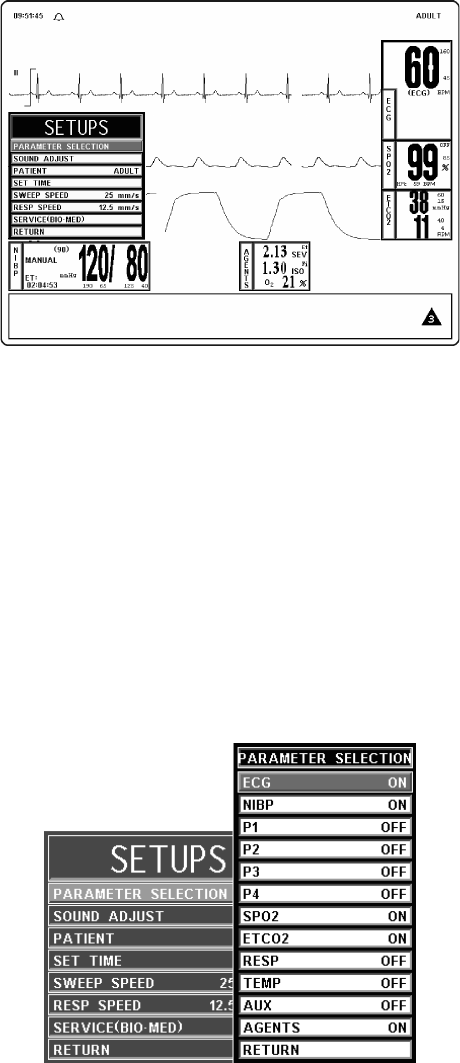
3-11
(d) RETURN. Selecting this menu option returns the monitor to the
SETUPS Menu.
(12) Return. Selecting this menu option returns the monitor to the Normal Screen.
Figure 3-10. WPU SETUPS Menu
b. WPU Setups Menu. While in the WPU SETUPS Menu, the available parameters
may be turned off and on, the monitor sounds may be adjusted, the patient mode may
be switched between adult and neonate, and the date and time may be adjusted. In
addition to control over these features, this menu allows the sweep speed and
respiration speed to be selected, and provides Qualified Service Personnel with Service
and Calibration Information. This menu has a time-out feature. If no action is taken for
approximately 60 seconds, the monitor will automatically return to the Normal
Screen.
The following is a description of the operation of the WPU SETUPS Menu options:
(1) Parameter Selection. To select this menu option, turn the Rotary Knob until
the PARAMETER SELECTION option is highlighted, then press the Rotary
Knob to select. Selecting this menu option will bring up the PARAMETERS
SELECTION Menu (See Figure 3-11).
Figure 3-11. The PARAMETER SELECTION Menu
Selection of this menu allows the operator to turn various parameters ON and
OFF. If the parameter selected is not installed, attempting to turn it ON will
cause the message “XXX IS NOT ENABLED” to be displayed. If the Freeze
feature is enabled, changes to parameter selections are not allowed; if Freeze is
enabled, the monitor displays a WARNING Box that alerts the operator that
this menu may not be accessed.

3-12
The following is a description of the PARAMETERS SELECTION Menu
options:
(a) ECG. Selecting this menu option will turn the ECG display ON
(default) or OFF. The heart rate will remain on the screen, allowing it to
be displayed from another source, if the heart-rate source (the HR
SOURCE selection) is set to AUTO.
(b) NIBP. Selecting this menu option switches the NIBP ON (default) and
OFF.
(c) P1. This option is not available on the 3160 MRI Physiological
Monitoring System.
(d) P2. This option is not available on the 3160 MRI Physiological
Monitoring System.
(e) P3. This option is not available on the 3160 MRI Physiological
Monitoring System.
(f) P4. This option is not available on the 3160 MRI Physiological
Monitoring System.
(g) SPO2. Selecting this menu option switches SpO2 ON and OFF.
(h) EtCO2. Selecting this menu option switches EtCO2 ON and OFF.
(i) RESP. This option is not available on the 3160 MRI Physiological
Monitoring System.
(j) TEMP. This option is not available on the 3160 MRI Physiological
Monitoring System.
(k) AUX. This option is not available on the 3160 MRI Physiological
Monitoring System.
(l) AGENTS. (If option is installed) Selecting this menu option switches
the Anesthetic Agent Option ON and OFF (default).
(m) RETURN. Selecting this menu option returns the monitor to the
Normal Screen.
(2) Sound Adjust. Selecting this menu option will bring up the SOUND
ADJUST Menu (See Figure 3-12) which allows the user to switch the Alarm
Tone ON and OFF, set the heart-rate tone source and set the volume for the
different sounds the 3160 MRI Physiological Monitoring System produces.
While in this menu, all real tones are disabled and the message “REAL
TONES DISABLED” is displayed at the top of the screen. Note that only the
sound is disabled and the violated alarms will still flash on the screen if the
parameter's Alarm Limit is violated. This menu has a time-out feature. If no
action is taken for approximately 60 seconds, the monitor will automatically
return to the Normal Screen.
NOTE
The WPU does not contain a speaker and, therefore, it will not make a sound. The following settings
will affect the operation of the DCU.
WARNING
The Alarm Tone can be set to OFF. Always check that the Alarm Tone setting is appropriate for each
particular patient. Alarm Sound volume is adjustable for suitability to various clinical environments
(where background noise may range from relatively quiet to noisy). Always verify that the user/
attendant of this monitor can hear the Alarm Sound above the ambient noise.
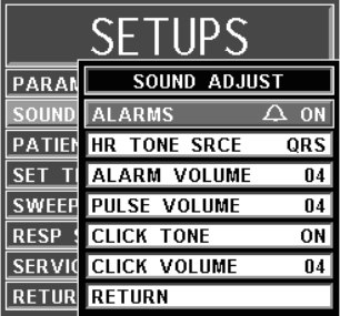
3-13
Figure 3-12. The SOUND ADJUST Menu
The following is a description of this menu's options:
(a) ALARMS. Selecting this menu option will turn the alarm sound ON
and OFF. When turned off, an “X” appears in the bell symbol on the
screen, and on the one in the menu option area, indicating that the
alarm sound has been disabled. This menu option is identical to, and
interactive with, the SOUND menu option in the ALARMS Menu.
(b) HR TONE SRCE. Selecting this menu option will select the heart rate
tone source. The options are OFF (default), QRS and SPO2. When
source is QRS, the tone sounds at the detection of QRS from the ECG
parameter. When source is SpO2, the tone sounds at the detection of the
pulse from the Pulse Oximeter parameter.
The pulse tone is modulated by the SpO2 value. The lower the
SpO2 value the lower the pitch of the pulse tone will be.
This menu option is identical to, and interactive with, the HR
TONE SOURCE Menu option in the ECG and SPO2 Menus.
(c) ALARM VOLUME. Selecting this menu option allows the selection
of volume for the Alarm Tone. The range is 1 - 10 (default is 4).
The 3160 Patient Monitoring System generates the Alarm Tone
(while in the VOLUME Menu) to provide the user with an audible
indication of the current volume-level setting.
(d) PULSE VOLUME. Selecting this menu option allows the selection of
volume for the pulse tone. The range is 1 - 10 (default is 4).
The 3160 Patient Monitoring System generates the pulse tone
(while in the VOLUME Menu) to provide the user with an audible
indication of the current volume-level setting.
(e) CLICK TONE. Selecting this menu option turns the click tone
generation of the device ON and OFF without affecting the adjusted
volume for the click tone.
(f) CLICK VOLUME. Selecting this menu option allows the selection of
volume for the click tone. The range is 1 - 10 (default is 4).
The 3160 Patient Monitor generates the click tone (while in the
VOLUME Menu) to provide the user with an audible indication of
the current volume-level setting.
(g) RETURN. Selecting this menu option returns the monitor to the
Normal Screen.
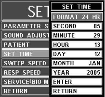
3-14
(3) Patient. Selecting this menu option determines the Adult (default) or the
Neonatal Mode for the operation of the ECG and NIBP parameters.
(a) ADULT. The initial NIBP inflation pressure is 170 mmHg. The
maximum inflation pressure is 285 mmHg. Also, the adult NIBP
pre-amplifier and the adult NIBP algorithm are used. ECG Heart Rate
detection sensitivity is 200 µV minimum.
(b) NEONATE. The initial inflation pressure is 120 mmHg. The
maximum inflation pressure is 150 mmHg. Also, the neonatal NIBP
pre-amplifier and the neonatal NIBP algorithm are used. ECG Heart
Rate detection sensitivity is 100 µV minimum.
(4) Set Time. Selecting this menu option will bring up the SET TIME Menu (See
Figure 3-13). From the SET TIME Menu the time and date may be set. The
time is displayed in the upper left corner of the screen. The clock continues to
operate when the power is off. The date format is MMM DD, YYYY (e.g., Jan
01, 2001). When a hard copy printout is made, the time and date is printed on
the edge of the printout.
Figure 3-13. The SET TIME Menu
The following is a description of the operation of the SET TIME Menu options:
(a) FORMAT. Selecting this menu option switches the format of the time
display between 12 hour and 24 hour.
(b) SECOND. Selecting this menu option allows scrolling through
seconds.
(c) MINUTE. Selecting this menu option allows scrolling through
minutes.
(d) HOUR. Selecting this menu option allows scrolling through hours.
(e) DAY. Selecting this menu option allows scrolling through days.
(f) MONTH. Selecting this menu option allows scrolling through months.
(g) YEAR. Selecting this menu option allows scrolling through years.
(h) ENTER. Selecting this menu option enters the newly-selected time
and date when all changes are completed.
NOTE
No new window is provided for the following selections. The setting to be adjusted becomes
highlighted within the existing menu.
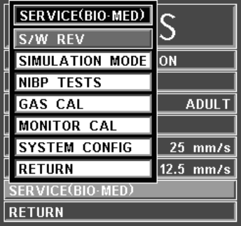
3-15
Pressing ENTER after the new time and date are completely set
puts the newly set time and date into effect. Otherwise, the old time
is restored upon exiting the SET TIME Menu.
(i) RETURN. Selecting this menu options returns the monitor to the
Normal Screen.
(5) Sweep Speed. Selecting this menu option will bring up the SWEEP SPEED
Menu. The SWEEP SPEED Menu allows the operator to switch the recorder
and the screen trace speed between 25 and 50 mm/second. This menu option is
identical to, and interactive with, the SWEEP SPEED menu option in
RECORDER Menu.
(6) Respiration Speed. Selecting this menu option will bring up the RESP
SPEED Menu. The RESP SPEED Menu allows the operator to set the
Respiration Speed at the following predetermined levels: 25 mm/s, 12.5 mm/s,
6.25 mm/s, 3.125 mm/s, 1.5625 mm/s and 0.33333 mm/s.
(7) Service (Bio-Med). Selecting this menu option will bring up the WPU
SERVICE (BIO-MED) Menu (See Figure 3-14). The WPU SERVICE
(BIO-MED) Menu provides the operator with the ability to identify the
Software Revision level, place the system into a Simulation Mode (used for
training purposes only), perform NIBP and SpO2 tests, calibrate the anesthetic
agent option (if available), calibrate the monitor and adjust the configuration of
the system.
Figure 3-14. The WPU SERVICE (BIO-MED) Menu
The following is a description of the options available in the SERVICE
(BIO-MED) Menu:
(a) S/W REV. Selecting this menu item brings up another window which
contains detailed inforation about the operating software of the WPU.
This window contains the revision level along with other technical
information concerning the WPU software. To exit this window, the
operator either selects the OK button on the window or the NORMAL
SCREEN key on the monitor front panel.
NOTE
The SERVICE (BIO-MED) Menu should only be used by qualified service personnel thoroughly
familiar with the operation and service of this monitor.
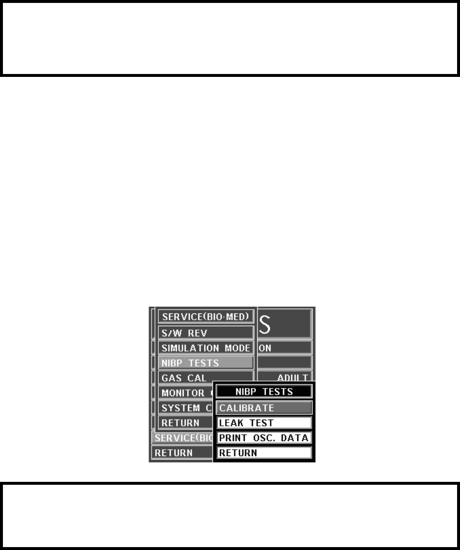
3-16
(b) SIMULATION MODE. This menu option allows the operator to turn
the Simulation Mode ON. When selected the monitor will first display
a YES/NO Menu and require user confirmation before entering the
Simulation Mode. While in the Simulation Mode the displayed patient
information is computer generated and not actual patient
determinations. As a safety feature, while in the Simulation Mode the
message “SIMULATION” is displayed in the center of the screen and,
when printing any strip or chart, “SIMULATION” will appear on the
printout. To exit the Simulation Mode, the monitor must be powered
Off.
(c) NIBP TESTS. Selecting this menu option will bring up the NIBP
TESTS Menu (See Figure 3-15).
The following options are provided in this menu:
•CALIBRATE. Selecting this menu option will display
NIBP CAL Offset Pressure and actual Pressure Reading in
the NIBP TESTS menu. These are used to verify and
calibrate the internal NIBP.
Figure 3-15. NIBP TESTS Menu
•LEAK TEST. Selecting this menu option will display
NIBP LEAK TEST with the Peak (beginning) Pressure
and Final (current) Pressure displayed, along with the
number of Passes and Failures of the test, to determine the
leak rate of the NIBP system. To begin this test, highlight
the LEAK TEST menu option and press the Rotary Knob;
to stop a test in progress, press the Rotary Knob a second
time.
WARNING
The Simulation Mode will display real looking waveforms which are computer generated. The
monitor will not monitor patients while in the Simulation Mode. Do not activate the Simulation
Mode when this monitor is connected to a patient. To exit the Simulation Mode, the monitor must
be powered Off.
WARNING
The Leak Test feature is for use by qualified service personnel only.
Never initiate a Leak Test while the cuff is applied to a patient. Continuous cuff pressure could lead
to patient injury.
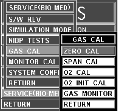
3-17
•PRINT OSC DATA. This option is for future service
enhancement.
•RETURN. Selecting this menu option returns the monitor
to the Normal Screen.
(d) GAS CAL. Selecting this menu option will bring up the GAS CAL
Menu (See Figure 3-16).
Figure 3-16. GAS CAL Menu
The following menu options are provided in this menu:
•ZERO CAL. Selecting this menu option will cause the
monitor to perform a Zero Cal of the Agent System.
•SPAN CAL. When the Agents option is installed, selecting
this menu option will bring up a password entry box
requiring a five (5) digit service code to access the
Anesthetic Agent Span Cal Service Menu.
•O2 CAL. Selecting this menu option will cause the monitor
to perform a one (1) minute calibration of the O2 Sensor.
•O2 INIT CAL. Selecting this menu option will cause the
monitor to perform a two (2) minute calibration of the O2
Sensor. This calibration should be performed after every
replacement of the O2 Sensor.
•GAS MONITOR. Selecting this menu option brings up the
Gas Monitor Calibration Box. This box contains Agent
Sensor Calibration characteristics which are used for factory
calibration.
•RETURN. Selecting this menu option returns the monitor
to the SERVICE (BIO-MED) Menu.
(e) MONITOR CAL. This menu option is intended for qualified Service
Personnel only. Selecting this menu option will first bring up a Yes/No
selection screen (See Figure 3-17) to ensure that this menu was not
selected by accident. When Yes is selected a second screen with
Calibration Information on various operational aspects of the monitor
appears (See Figure 3-18).
• If this display should be selected, exit by turning the
monitor off.
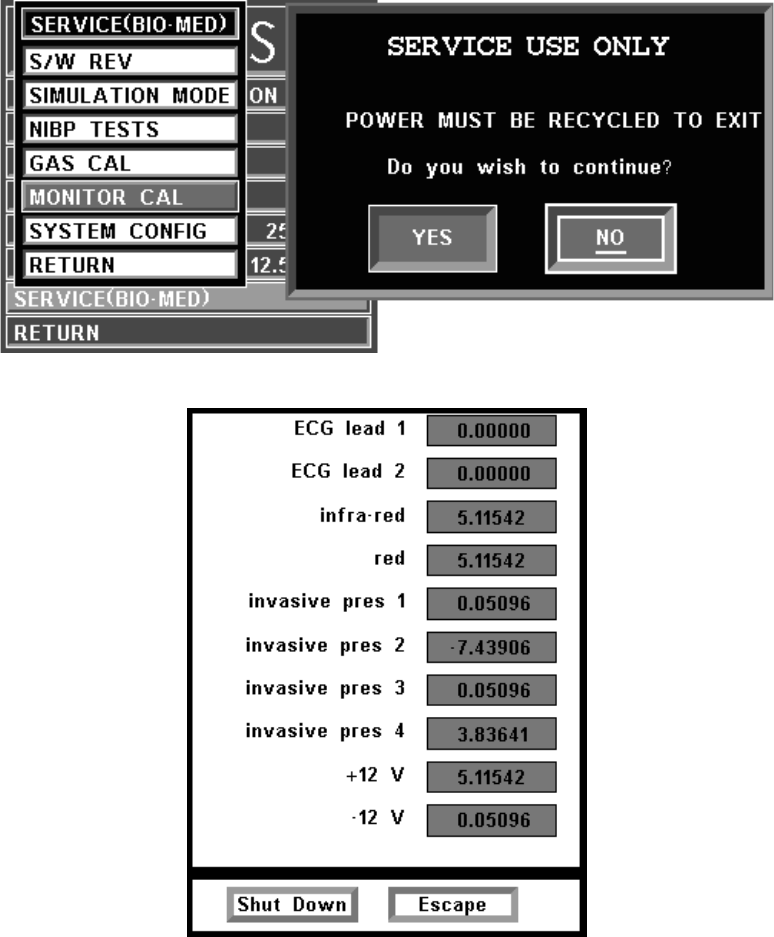
3-18
• It is important to note that if the Escape option is selected,
the monitor will return control of the monitor to the operator
but the Calibration Screen will remain on the display; to
remove the Calibration Screen turn the monitor off.
Figure 3-17. Monitor Calibration YES/NO Menu
Figure 3-18. Monitor Calibration Information Screen
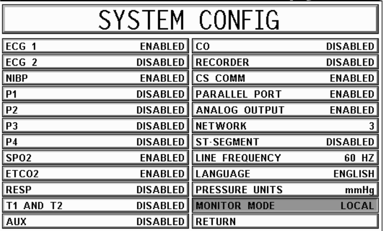
3-19
Figure 3-19. System Configuration Menu
(f) SYSTEM CONFIG. The SYSTEM CONFIG Menu (See Figure 3-
19) is brought up by selecting the SYSTEM CONFIG Menu option.
Most of the options in this menu are sensitive and are, as a result,
protected by a five (5) digit password that must be entered before the
option may be adjusted. The Language and Pressure Unit options are
the only options in this menu which do not require that the service code
be entered.
The following options are available in this menu:
•ECG 1: Selecting this menu option will enable/disable the
ECG 1 module.
•ECG 2: This option is not available on the 3160 MRI
Physiological Monitoring System.
•NIBP: Selecting this menu option will enable/ disable the
NIBP module.
•P1: This option is not available on the 3160 MRI
Physiological Monitoring System.
•P2: This option is not available on the 3160 MRI
Physiological Monitoring System.
•P3: This option is not available on the 3160 MRI
Physiological Monitoring System.
•P4: This option is not available on the 3160 MRI
Physiological Monitoring System.
•SPO2: Selecting this menu option will enable/disable the
SpO2 module.
•EtCO2: Selecting this menu option will enable/disable the
EtCO2 module (if installed).
•RESP: This option is not available on the 3160 MRI
Physiological Monitoring System.
•TEMP 1 AND 2: This option is not available on the 3160
MRI Physiological Monitoring System.
•AUX: This option is not available on the 3160 MRI
Physiological Monitoring System.
3-20
•CO: This option is for future service enhancement.
•RECORDER: Selecting this menu option will enable/
disable the RECORDER module.
•CS COMM: Selecting this menu option will enable/disable
CS COMM.
•PARALLEL PORT: Selecting this menu option will
enable/disable the Parallel/Printer Port.
•ANALOG OUTPUT: Selecting this menu option will
enable/disable the Analog Output Port.
•NETWORK: Selecting this menu option provides a
method of connecting to a specific network.
•ST-SEGMENT: This option is not available on the 3160
MRI Physiological Monitoring System.
•LINE FREQUENCY: Selecting this menu option switches
the ECG Notch Filter between 50 Hz and 60 Hz. This filter
does not apply to ECG Diagnostic Filter Mode.
•LANGUAGE: Selecting this menu option allows the
Language of the monitor to be switched between the
available languages (English, German, Spanish, Portuguese,
Italian, Dutch, Swedish and French). To enable the language
change, the operator must exit the SYSTEM CONFIG
menu by selecting Return or pressing the NORMAL
SCREEN control key, and then turn the monitor Off then
On.
•PRESSURE UNITS: Selecting this menu option allows the
Blood Pressure and EtCO2 Measurement units to be
switched between mmHg and kPa. See Appendix E for a
kPa to mmHg Conversion Chart.
•MONITOR MODE: This menu item is set automatically
depending on which unit is be looked at. For the DCU, this
option is set to REMOTE MODE. For the WPU, this option
is set to LOCAL MODE.
•RETURN: Selecting this menu option returns the monitor
to the Service (Bio-Med) Menu.
(g) RETURN. Selecting this menu option returns the monitor to the
SETUPS Menu.
(8) Return. Selecting this menu option returns the monitor to the Normal Screen.
3.3 Store/Recall Setups. (DCU Only) The 3160 MRI Physiological Monitoring System has
seven (7) memory blocks, each of which has enough capacity for the current setting of every control
setup, alarm limits, trend time base, etc. on the monitor. The operator is able to store and recall seven
different configurations of the monitor. The seventh (USER DEFAULTS) is also used for recall at
monitor power up. The memory blocks are maintained by a long-life battery, or static RAM memory,
which will keep the memory contents intact even when power is off.
Settings for the monitor can be stored for different procedures, different types of patients, etc., or multi-
ple users of the monitor can store and recall their own preferred configurations without having to indi-
vidually set each limit, status, etc., before each use.
Each storage memory block maintains the settings for:
a. ALARMS. The setting of MIN and MAX values. auto-set percentage, latched or
non-latched selection for alarms, and alarm tone enabled/disabled.
b. SYSTEM SETUPS. All Settings.

3-21
c. ECG. Selected lead, scale setting, trace speed, filter mode, QRS tone ON/OFF and
heart rate source.
d. RECORDER. Off or auto, trace delay, recorder speed and the selected traces.
e. NIBP. Manual, off or auto and the automatic time interval.
f. EtCO2. Size, grids and flow.
g. TREND GRAPHS. Time bases and scales.
h. SpO2. Size.
Once the monitor is setup properly, the setups may be stored in one of the available memory blocks.
The stored setups can be brought up via the RECALL SETUPS Menu.
3.4 Monitor Initialization. The monitor may start its monitoring functions from either an initial
(Factory Settings) state or a pre-configured state depending on how the stored configuration
information and patient data (trends, tabular data, and reports) are treated on start-up.
3.4.1 Default Initialization. The monitor's master processor is "cold-started" by pressing and
holding the Rotary Knob then the NORMAL SCREEN key while turning power on (See Paragraph
2.3.1.g for further information). If the monitor is cold started, it will revert to Factory Default
Settings. The screen displays the following:
a. The Bell Symbol with “H” in it appears in the upper portion of the screen under
ALARM STATUS.
b. ECG 1 is on in Trace A and set to Lead II.
c. SpO2 is on with waveform displayed in Trace C.
d. NIBP is on and displayed in the lower left portion of the screen.
e. The “SOUND ON HOLD” message is displayed in the center of the screen and counts
down starting from 180.
f. All other parameters are off.
g. The alarm sound is enabled when the SOUND ON HOLD count reaches 0.
3.4.2 Pre-Configured Initialization. A “warm-start” occurs whenever the monitor power is cycled
(turned off then back on).

4-1
SECTION 4
PATIENT PARAMETERS
4.0 PATIENT PARAMETERS.
4.1 ECG Monitoring. Unless it has been turned off in the ECG Menu, the selected ECG lead is
displayed as TRACE A. Most ECG functions are contained in the ECG Menu. Additional features
useful with ECG monitoring are found in three secondary menus:
•RECORDER Menu. Used to select all recorder functions and to set the recorder
and trace speed.
•ALARMS Menu. Used to set and/or disable the ECG alarms. The range of Alarm
Limits for the ECG Heart Rate is 30 to 249 bpm.
•HEART RATE Trend Menu. Used to setup and print Trended information.
For further information on the secondary menus, see the corresponding paragraphs of this
document.
4.1.1 Patient and Lead Preparation. Acquisition of the patient's ECG signal is achieved with a
Invivo approved patient cable with the appropriate lead wires and electrodes. Patient skin preparation,
type of electrode used, and technique used to apply electrodes are major factors that can affect the
quality of tracing displayed on the monitor. To obtain a tracing with baseline stability and to reduce
artifact due to patient movement the following guidelines should be followed.
a. Patient Skin Preparation. Prepare the patient's skin as follows:
• Shave hair from electrode placement sites.
• Cleanse skin thoroughly to remove skin oil, or any other substance that can
increase impedance (avoid using alcohol as it tends to overdry the skin
causing flaking which increases impedance). For best results use Invivo
Skin Prep #9009.
• Gently abrade the skin with gauze or rough material to remove dry skin.
b. Electrodes. Check the electrodes for the following:
• Use electrodes of the same type/brand to ensure consistent impedance
levels.
• Ensure electrodes do not exceed the expiration date.
• Ensure that the conduction gel is moist to the touch.
c. Electrode Placement. Place the electrodes as follows:
• Attach electrodes to the lead wires prior to placing on the patient.
• Place black electrode on left shoulder under left clavicle.
• Place white electrode on right shoulder under right clavicle.
• Place red electrode on lower left abdomen under the sixth rib.
• Place the green electrode on the lower right abdomen under the ribs.
d. Attaching the ECG Cable. Attach the ECG cable to the ECG Patient Connector on
the WECG telemetry transmitter.
Figure 4-1. ECG Trace and Numerical Displays
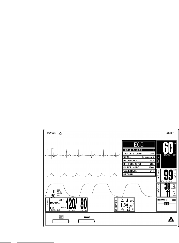
4-2
4.1.2 Associated Waveforms and Displays. (See Figure 4-1) ECG information is displayed as a
waveform in the Trace A location and as numeric data in the Box 1 and 2 locations. The following is a
description of the items contained within the ECG Display.
a. ECG Lead. (Item 1) Displays the ECG Lead selected for use.
b. Scale Indicator. (Item 2) This indicator is provided for a reference and represents a 1
millivolt signal amplitude.
c. Message Areas. (Item 3) These areas display software messages: the area on the left
displays ECG specific messages while the larger area on the right displays all types of
monitor messages.
d. Waveform Traces. (Item 4) Displays the ECG waveform of the patient.
e. Heart Rate Numeric. (Item 5) Displays the current Heart Rate indication for the
patient.
f. Alarm Limit High. (Item 6) Displays the value set for the High Limit of the ECG
Heart Rate Alarm. This istem is under operator control and may be turned on or off as
required.
g. Alarm Limit Low. (Item 7) Displays the value set for the Low Limit of the ECG
Heart Rate Alarm. This item is under operator control and may be turned on or off as
required.
h. Heart Rate Source. (Item 8) Displays the source selected for the Heart Rate.
Figure 4-2. The ECG Menu
4.1.3 The ECG Menu. (See Figure 4-2) Selecting the ECG Menu-Select Icon brings up the ECG
Menu. This menu has a time-out feature. If no action is taken for approximately 60 seconds, the
monitor will automatically return to the Normal Screen.
The following selections are available in the ECG Menu:
a. TRACE A LEAD. Selecting this menu option allows the selection of the ECG 1 lead.
The options are II (default) and OFF.
b. TRACE B LEAD. This option is not available on the 3160 MRI Physiological
Monitoring System.
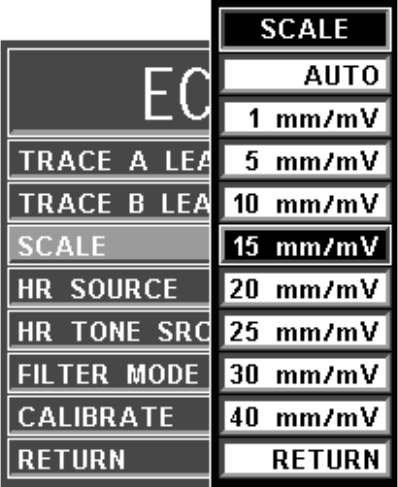
4-3
Figure 4-3. The ECG SCALE Sub-Menu
c. SCALE. Selecting this menu option allows the selection of the scale for the ECG
waveform(s). The options are AUTO, 1, 5, 10, 15 (default), 20, 25, 30, and 40 mm/mv
(See Figure 4-3). The selected scale appears on the right hand side of this menu option.
If AUTO is selected, a scale is picked that would make the current waveform(s) fill the
ECG viewing area. This scale will be in effect until another scale is selected (AUTO or
any other selection). A Scale Indicator associated with the Trace is displayed on the left
side of the screen, and denotes a 1 millivolt signal amplitude.
(1) If the scale of the ECG trace is so large that the top or bottom of the ECG
waveform is distorted or flattened, the “OVERSCALE” message flashes in
the ECG waveform area. This message will override other ECG error
messages. Use the SCALE menu option (in the ECG Menu) to resize the
waveform until the “OVERSCALE” message stops flashing. If this continues,
the Auto Scale option should be selected to prevent further waveform
distortion.
(2) The ECG waveform in may be frozen for closer examination by pressing the
FREEZE control key. When the waveform is frozen, it is displayed below
Trace A with a “Blue Box” around it. While Freeze is enabled, changes to the
Parameter Selections are not allowed; if the operator tries to access the
PARAMETER SELECTION menu, a WARNING Box appears to alert the
operator that the selected menu may not be accessed.
d. HR SOURCE. Selecting this menu option allows the selection of the source to be used
for the heart-rate display in TRACE A area. The options are AUTO, ECG (default),
ART, SPO2 and NIBP (See Figure 4-4).
NOTE
Invasive Pressure is not available with this system. If ART is selected as the HR SOURCE a
Warning box appears that informs the operator that this option is not available.
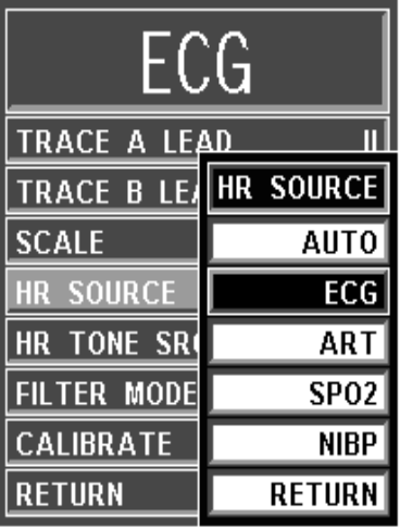
4-4
Figure 4-4. The ECG HR SOURCE Sub-Menu
(1) The heart rate is displayed in the ECG parameter box. It is annotated with its
source (e.g., “60 ECG” indicates a heart rate of 60, derived from ECG).
(2) If AUTO is chosen, the heart rate is selected automatically from the
highest-priority active input. When set to AUTO the 3160 Vital Signs
Monitoring System searches for another source for rate only when LEAD
FAIL occurs or the ECG parameter is turned OFF. The priority, from highest
to lowest, is ECG, SpO2, and NIBP.
(3) The 3160 Vital Signs Monitoring System examines the highest-priority
active input. If not found, it will go to the next-highest priority parameter. If
none of the parameters are presenting a heart rate and NIBP is shut off, then
“NONE” is displayed on the screen in the heart rate position.
(4) HR Tone Source is only set for ECG or SpO2.
(5) This menu option is identical to, and interactive with, the similarly named
menu options under SPO2 and NIBP.
e. HR TONE SRCE. Selecting this menu option selects the source to be used for the
heart-rate tone. The options are QRS, SPO2 and OFF (default). When this parameter is
set to OFF, the Heart Symbol will not be displayed.
(1) When the SpO2 parameter provides the heart rate tone, the tone is modulated
by the SpO2 value.
(2) If the Heart Rate Tone source is turned off, the Heart Symbol is removed from
the display.
(3) This menu option is identical to, and interactive with, the HR TONE SOURCE
option in the SOUND ADJUST Menu.
f. FILTER MODE. Filter Mode is permanently set to MON (monitor) with bandwidth
of 0.5 to 40 Hz.
g. CAL. Selecting this menu option opens the CALIBRATE Menu. This menu option is
identical to and interactive with the calibrate option in the RECORDER Menu. The
following options are available in the CALIBRATE Menu:

4-5
(1) OFF. Selecting this menu option turns the Calibration feature OFF.
(2) RECORDER. Selecting this menu option sends a 1mV pulse calibration
waveform to the ECG Vital Sign and will also be the ECG waveform printed
by the recorder if so configured. The message CAL is displayed over the ECG
waveform on the screen.
(3) ECG. Selecting this menu option sends a 2mV peak to peak (1mV peak)
calibration signal to the ECG vital sign and will also be the ECG waveform
printed by the recorder if so configured. The message CAL is displayed over
the ECG waveform on the screen. It is important to note that this is a hardware
generated calibration waveform and originates as a square wave.
(4) RETURN. Selecting this menu option closes the CALIBRATE Menu.
h. RETURN. Selecting this menu option will return the monitor to the Normal Screen.
4.1.4 Alarm Limits. Alarm Limits may be set two ways. To set the Alarm Limits for every
available parameter, from the Normal Screen (with no icons highlighted), press the ALARMS
SCREEN Menu-Select Key. To set the Alarm Limits for ECG Heart Rate only, highlight the ECG
Icon and press the ALARMS SCREEN Menu-Select Key to access the individual parameter Alarm
Limits Box. The range of Alarm Limits for the ECG Heart Rate is 30 to 249 bpm.
4.1.5 Trended Data. For complete information on the trending of patient ECG data, see Section 5:
Printing and Trending.
4.1.6 ECG Messages. The following is a list of messages that may be displayed during ECG
monitoring:
4.2 Non-Invasive Blood Pressure (NIBP) Monitoring. The NIBP feature measures and
displays systolic, diastolic and mean arterial pressures, and pulse rate. LOW and HIGH Alarm Limits
are available for all three pressures. When the 3160 Vital Signs Monitoring System is configured to
obtain the patient's heart rate from the NIBP, the heart rate alarm is also applicable to this parameter.
The monitor may be set to take NIBP readings at automatic intervals from 1 to 240 minutes (there is a
20 second pause between readings to allow for peripheral perfusion), or the operator can manually
initiate a reading at any time.
When a successful reading is taken, the elapsed time display indicates the beginning of this cycle.
The time until next measurement indicates when the next automatic measurement will be made. A
manual reading does not restart this cycle time. The NIBP INTERVAL key may be used to
adjust the cycle time. The NIBP START/STOP key may be used to manually start/stop a
measurement. The NIBP STAT key allows the start of STAT Mode (which makes up to five (5)
NIBP determinations in rapid succession).
If an error is detected, the Alarm Tone will sound, and an error message will be written on the
screen.
Non-Invasive blood pressure monitors are sensitive to patient motion artifact. Such artifact can
cause readings to be slow or even an incorrect pressure reading.
Visual checks of the patient, other vital signs and checking the limb to which the cuff is attached
should be standard routines with NIBP use.
LEAD FAIL LEAD FAIL is displayed when a faulty ECG Lead is detected by the
system.
OVERSCALE OVERSCALE is displayed if the scale of the ECG Trace is so large
that the tops of the ECG waveforms are being “clipped” (the tops and
bottoms cut off). This message suppresses all other ECG Error
Messages and the Alarm Tone will not sound. To reduce the scale,
and remove the OVERSCALE message, access the SCALE menu
option in the ECG Menu.
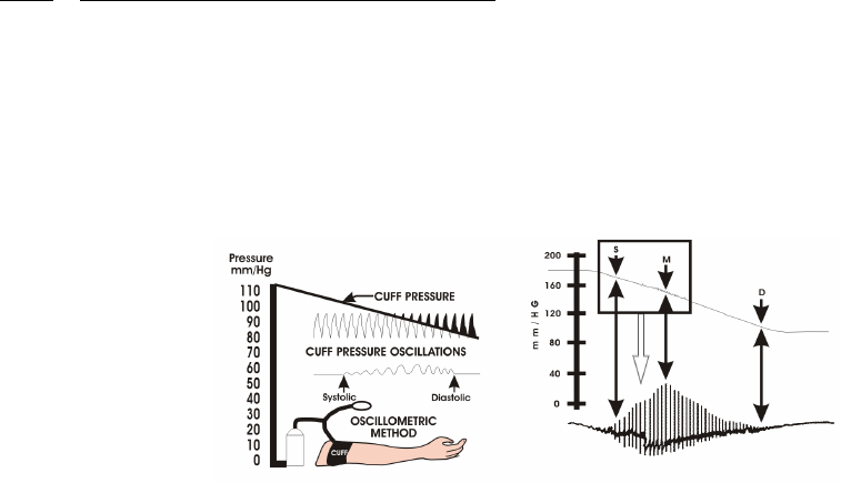
4-6
If a measurement is in progress and communication is lost between the DCU and WPU, the
measurement is aborted.
Most NIBP functions are contained in the primary NIBP Menu. However, additional features
useful with NIBP monitoring can be found in the three secondary menus associated with this
parameter:
•RECORDER Menu. Used to select recorder functions and to set the recorder
trace speed.
•ALARMS Menu. Used to set and/or disable the NIBP alarms. The range of Alarm
Limits for the NIBP is 5 to 249 mmHg.
•NIBP Trend Menu. Used to setup and print Trended information.
4.2.1 Theory of Oscillometric Measurement. This monitor obtains blood pressure measurements
based on the Oscillometric principle. Oscillometric Monitors use an inflatable occlusive cuff which
can also be used in the manual auscultatory technique; however, rather than monitoring Korotkoff
sounds, Oscillometric Monitors detect and measure oscillations induced in the cuff by the movement
of the arterial wall. In basic terms, oscillometric monitors utilize a pressure transducer which is
connected to the cuff via a hose. The transducer transforms the oscillations induced into the cuff
pressure into electrical currents. Under control of a microprocessor and software algorithms, the
electrical current can then be measured and correlated with the cuff pressure to determine arterial blood
pressure. The following describes the process of Oscillometric Measurement:
Figure 4-5. Oscillometric Measurement Method
a. As the occlusive cuff is inflated to a suprasystolic pressure the artery is occluded so that
no blood passes through. At this point, even though no blood flows under the cuff,
there are small pulsations induced into the cuff pressure by the partially-occluded
proximal portion of the artery lying under the cuff (See Figure 4-5).
b. As cuff pressure is reduced to just below the systolic pressure, the force of the height of
the systolic pressure wave forces the occluded artery open, blood spurts through the
artery and the amplitude of the oscillations increase sharply. This is the systolic
pressure.
c. With further reduction in cuff pressure the artery opens for a longer time during each
cardiac cycle, which causes increasingly larger oscillations in the cuff pressure until
they reach a point of maximum oscillation amplitude. This point of maximum
oscillations has been well-demonstrated to be Mean Arterial Pressure.
d. With continued cuff-pressure reduction, the underlying artery is open throughout the
cardiac cycle, and the arterial-wall movement is less. The cuff pressure oscillations
begin to decrease in amplitude until they become uniform. The point at which the
amplitudes become uniform is diastolic pressure.
NOTE
The point of maximum oscillations is coincident with mean arterial pressure regardless of arterial
elasticity so long as the ratio of air volume in the cuff to the volume of the artery under compression
does not greatly exceed ten (10) to one (1). For this reason it is advisable to keep the cuff air volume
to a minimum by using the smallest cuff size possible for each patient.
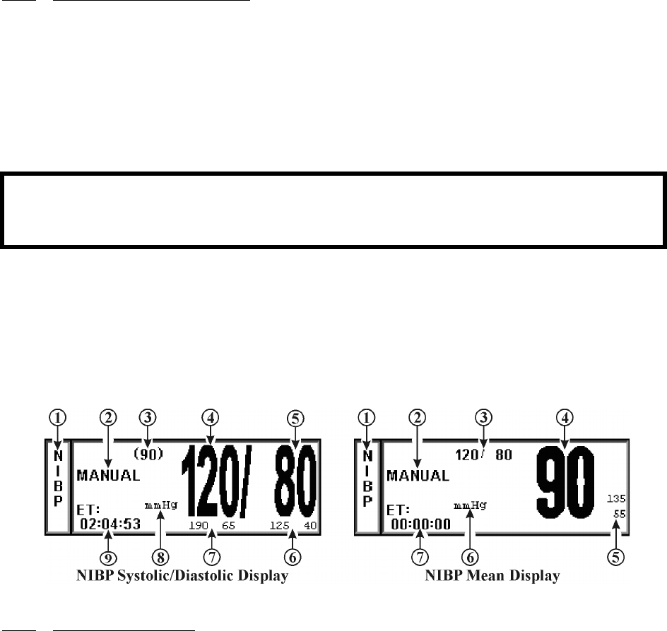
4-7
4.2.2 Patient and Cuff Preparation. The patient should remain calm and motionless while the
monitor is being used. If the patient is overactive, prolonged or inaccurate readings may result.
Perform the following to prepare the patient and cuff for monitoring:
a. Cuff Selection. The cuff is selected and positioned as it would be for an auscultatory
blood pressure determination, and the current guidelines of the American Heart
Association should be followed. The bladder width of the cuff should be 40% of the
circumference of the limb. For a correct fit on adult and pediatric cuffs, the Index line
on the end of the cuff must fall between the two Range lines printed on the inside of the
cuff. For correct fit on neonatal cuffs, choose the size with the stated circumference
range that fits the circumference of the limb of the neonate.
b. Cuff Positioning. The cuff should be wrapped firmly (not snug) around the arm of the
patient and positioned as close to heart level as possible. If the cuff is not at heart level,
add 1.8 mmHg to the displayed readings for each inch that the center of the cuff is
located above the patient's heart level; subtract 1.8 mmHg from the displayed readings
for each inch that the cuff is located below the patient's heart level.
c. Cuff Connections. Select the proper hose (twin-lumen for adults, single-lumen for
neonates), and attach hose to cuff. Route the hose from the cuff to the monitor so it does
not kink, tangle or limit access to the patient.
Figure 4-6. The NIBP Display
4.2.3 Associated Displays. When NIBP is enabled, it is displayed in a box at the lower left of the
normal screen. The box is a specialized display panel that includes the information concerning the
NIBP status in one of two user selectable formats. The two available formats are Systolic/Diastolic and
Mean Only (See Figure 4-6); the user selects the format using the FORMAT option in the NIBP
Menu (See Paragraph 4.2.5). The two available displays are described below:
a. The NIBP Systolic/Diastolic Display. The items contained in this user selectable
display are described below:
(1) Icon Label. (Item 1) This label identifies the parameter whose numeric data is
being displayed within the Icon Box. Box 11 (in the lower left of the Bottom
Numeric Display) is dedicated to the display of NIBP information.
(2) Manual. (Item 2) While in the Automatic Mode, “NEXT” is shown and the
time until the next NIBP determination is displayed here; in the Manual Mode,
the word “MANUAL” is displayed here.
(3) Mean Numeric. (Item 3) A numeric indication of the patient's Mean pressure
reading.
(4) Systolic Numeric. (Item 4) A numeric indication of the patients NIBP
Systolic reading.
WARNING
Do not attach the cuff to a limb being used for infusion. Cuff inflation can block the infusion causing
possible harm to patient.
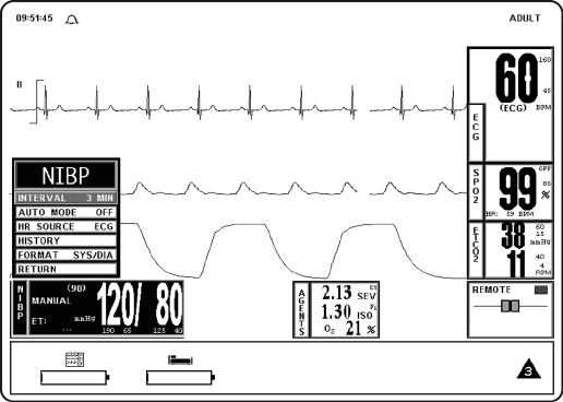
4-8
(5) Diastolic Numeric. (Item 5) A numeric indication of the patients NIBP
Diastolic reading.
(6) Diastolic Alarm Limits. (Item 6) A numeric indication of the settings of the
High (to the left in the example) and Low (right in the example) Diastolic
Alarm Limits.
(7) Systolic Alarm Limits. (Item 7) A numeric indication of the settings of the
High (to the left in the example) and Low (right in the example) Systolic Alarm
Limits.
(8) Unit of Measurement. (Item 8) Displays the Unit of Measurement being used
for presentation of the numeric data. This item may be toggled between mmHg
and kPa using the System Configuration Menu (See Section 3 for further
information).
(9) ET. (Item 9) The Elapsed Time (ET) since the last NIBP determination is
displayed here. During an NIBP determination, this message changes to
display the cuff pressure.
b. The NIBP Mean Display. The items contained in this user selectable display are
described below:
(1) Icon Label. (Item 1) This label identifies the parameter whose numeric data is
being displayed within the Icon Box. Box 11 (in the lower left of the Bottom
Numeric Display) is dedicated to the display of NIBP information.
(2) Manual. (Item 2) While in the Automatic Mode, “NEXT” is shown and the
time until the next NIBP determination is displayed here; in the Manual Mode,
the word “MANUAL” is displayed here.
(3) Systolic/Diastolic Numeric. (Item 3) A numeric indication of the patient's
Systolic/Diastolic pressure reading.
(4) Mean Numeric. (Item 4) A numeric indication of the patients NIBP Mean
reading.
(5) Mean Alarm Limits. (Item 5) A numeric indication of the settings of the High
(on top in the example) and Low (bottom in the example) Mean Alarm Limits..
(6) Unit of Measurement. (Item 6) Displays the Unit of Measurement being used
for presentation of the numeric data. This item may be toggled between mmHg
and kPa using the System Configuration Menu (See Section 3 for further
information).
(7) ET. (Item 7) The Elapsed Time (ET) since the last NIBP determination is
displayed here. During an NIBP determination, this message changes to
display the cuff pressure.
Figure 4-7. The NIBP Menu
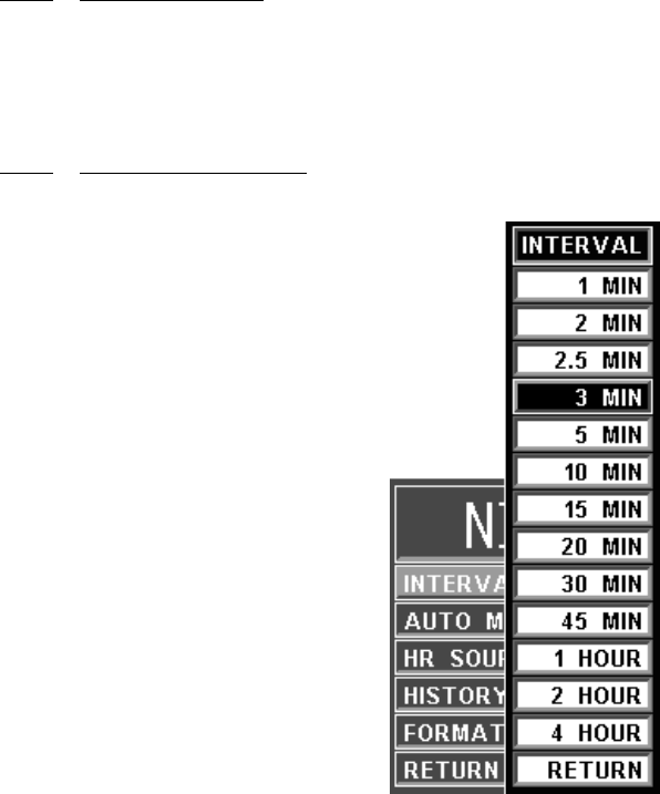
4-9
4.2.4 The NIBP Menu. Selecting the NIBP Menu-Select Icon will bring up the NIBP Menu (See
Figure 4-7). This menu provides the operator with the ability to switch the Automatic Mode On and
OFF, set the automatic reading interval, set the Heart Rate source and bring up a Tabular Chart
containing a History of the NIBP and SpO2 determinations. This menu has a time-out feature. If no
action is taken for approximately 60 seconds, the monitor will automatically return to the Normal
Screen.
4.2.5 NIBP Menu Options. The following is a description of the operation of the NIBP Menu
options:
Figure 4-8. The NIBP INTERVAL Menu
a. INTERVAL. Selecting this menu option allows the operator to change the
automatic-measurement time interval setting (See Figure 4-8). The options are 1, 2,
2.5, 3 (default), 5, 10, 15, 20, 30 or 45 minutes, and 1, 2 or 4 hours. The INTERVAL
Menu is also accessed by pressing the NIBP INTERVAL key.
(1) There is a 20-second period in between the measurements to allow for
peripheral perfusion.
(2) As the Rotary Knob turns clockwise, the interval selection will increase. After
reaching “RETURN,” the interval selection will “roll over” to “1 MIN” and
continue to increase.
(3) As the Rotary Knob turns counter-clockwise, the interval selection will
decrease. After reaching “1 MIN,” the interval selection will “roll over” to
“RETURN” and continue to decrease.
b. AUTO MODE. Selecting this menu option allows the operator to switch the NIBP
Automatic Mode between ON and OFF (default). When switched from OFF to ON,
the operator must manually initiate the first reading (by pressing the NIBP START/
STOP control key); subsequent readings are taken automatically at the operator
selected interval. When in MANUAL mode, readings may only be initiated from the
NIBP START/STOP or NIBP STAT control keys. A reading cycle may be stopped
at any time if the NIBP START/STOP control key is pressed while it is in progress

4-10
c. HR SOURCE. Selecting this menu option allows the selection of the source to be used
for the heart-rate display in the ECG area. The options are AUTO, ECG (default), ART
(arterial pressure), SPO2 and NIBP.
This menu option is identical to, and interactive with, similarly named menu options
under ECG and SPO2.
Figure 4-9. The HISTORY Menu
d. HISTORY. Selecting this menu option brings up the HISTORY Menu (See Figure
4-9), and displays the last 48 NIBP readings together with the heart rate, SpO2, CO2
and respiration values at the time in a tabular form (6 readings per page). The tabular
data is retained in non-volatile memory when power is interrupted.
The following options are available in the HISTORY Menu:
(1) PRT ALL. Selecting this menu option prints all stored Tabular Data.
(2) PRT PAGE. Selecting this menu option prints the current page.
(3) PREV PAGE. Selecting this menu option allows the selection of the previous
page of tabular data.
(4) NEXT PAGE. Selecting this menu option allows the selection of the next
page of the tabular data.
(5) CLEAR ALL. Selecting this menu option clears the patient Trend Data.
(6) RETURN. Selecting this menu option will return the monitor to the NIBP
Menu.
e. FORMAT. Selecting this menu option allows the operator to change the display
format of the Pressure numerics. If SYS/DIA is selected, the Systolic and Diastolic
numerics will be in a large font separated by a “slash” and the Mean numeric will be in
a smaller font bracketed with parenthesis. If MEAN is selected, the Mean numeric is
displayed in the large font with the Systolic and Diastolic numerics separated by a
“slash” in a smaller font.
f. RETURN. Selecting this menu option will return the monitor to the Normal Screen.
NOTE
Invasive Pressure is not available with this system. If ART is selected as the HR SOURCE a
Warning box appears that informs the operator that this option is not available.
NOTE
History Data is retained when a new patient is connected to the monitor. Therefore, to avoid
confusion, all previously acquired data should be cleared prior to connection to a new patient.

4-11
4.2.6 Using the Automatic Interval Mode This monitor may be setup to take NIBP readings
automatically at intervals set by the operator. To set this monitor to make automatic NIBP
determinations, turn the Rotary Knob until the NIBP Menu-Select Icon is highlighted and then press
the Rotary Knob to bring up the NIBP Menu. To set the Interval Time, highlight the INTERVAL
menu selection and press the Rotary Knob to access the time selection menu. To turn the Automatic
Mode of Operation ON or OFF, highlight the AUTO MODE menu selection, press the Rotary Knob
and select ON or OFF. Once the Automatic Mode has been turned On, press the NIBP START/STOP
Control Key to activate.
4.2.7 Manually Starting/Stopping a Reading Cycle An NIBP cycle may be started or stopped by
pressing the NIBP START/STOP Control Key.
4.2.8 Stat Mode Operation The STAT Mode is specifically intended for clinicians who need to
obtain successive readings for rapid assessment of the trend of a patient's pressures. To initiate a series
of up to five STAT Readings, the operator presses the NIBP STAT Control Key. The monitor will
perform up to five NIBP cycles in a period of five (5) minutes. At the end of the five (5) minute period,
the STAT Mode will terminate (even if a reading is in progress) regardless of how many readings have
been completed.
4.2.9 Alarm Limits Alarm Limits may be set two ways. To set the Alarm Limits for every available
parameter, from the Normal Screen (with no icons highlighted), press the ALARMS SCREEN Menu-
Select Key. To set the Alarm Limits for NIBP only, highlight the NIBP Icon and press the ALARMS
SCREEN Menu-Select Key to access the individual parameter Alarm Limits box. The range of Alarm
Limits for the NIBP pressure channels is 5 to 249 mmHg.
4.2.10 Adult vs. Neonatal Mode Operation This monitor allows the operator to determine pressures
on a wide range of patients by allowing the Patient Type to be switched from Adult to Neonate (Adult
Mode is used for Adult and Pediatric patients and Neonate Mode is used for Neonates only). Several
operational parameters (including cuff inflation pressure) are varied depending on the setting of the
PATIENT menu option in the SETUPS Menu. The Adult/Pediatric Mode uses a higher pump
volume and a much larger cuff is used on the patient; in the Neonatal Mode the pump rate is lower and
a much smaller cuff is used on the patient (reference pages xvii, xviii and xix of this manual for cuff
selection and sizes). The Alarm Limits and settings may also change when the patient type is switched
from adult to neo (or neo to adult).
Whenever the NIBP Patient Mode is switched (either from Adult to Neo or Neo to Adult), for
20 seconds the Alarm Tone will sound while the informational display message area indicates
“Change NIBP Cuff.” To change the patient type, press the SETUP control key, scroll to the
PATIENT menu selection and press the Rotary Knob. The “WRONG CUFF” NIBP message
will appear if a reading is initiated and the monitor detects that an incorrect cuff is being used for
the selected patient mode (Adult or Neonate). Replace the patient cuff with the appropriate size
cuff and press the NIBP START/STOP control a second time, this will re-initiate the reading.
4.2.11 Trended Data. For complete information on the trending of patient NIBP data, see Section 5:
Printing and Trending.
WARNING
The patient's blood pressure determinations are not continuous. The blood pressure determinations
are only updated immediately after a blood pressure measurement is taken. When set to the shortest
of the automatic intervals, the constant measurements can cause blood pooling in the limb, and
blood pooling in the limb may artificially increase the value of the blood pressure determinations.
WARNING
The initial cuff inflation pressure will increase to 170 mmHg when changing the patient mode from
Neonate to Adult.

4-12
4.2.12 NIBP Messages. The following is a list of messages that may be displayed during NIBP
monitoring:
4.3 SpO2 Monitoring. The SPO2 Menu is brought up (if this parameter is turned on through the
SETUPS Menu) with the SPO2 Menu-Select Icon.
The following three secondary menus support the SpO2 monitoring feature:
•RECORDER Menu. Used to select recorder functions and to set the recorder and
trace speed.
•ALARMS Menu. Used to set and/or disable the SpO2 alarms. The range of Alarm
Limits for SpO2 is 50 to 99%, Off.
•SpO2 Trend Menu. Used to setup and print Trended information.
4.3.1 Sensor Positioning. The monitoring site, sensor position, sensor connection and the ambient
environment all have possible impacts on the operation of this monitor. The following is a list of
possible messages (which are indicated in the SpO2 display), their causes and possible solutions:
a. LOW LIGHT. The transmission of the light is partially blocked. The tissue at the site
may be too opaque and/or thick. If the sensor is positioned on the finger, check the
fingernails for nail polish, long fingernails and artificial fingernails; remove fingernail
polish completely, for artificial nails: use a Multi-Site sensor at another location, and,
for long fingernails: either trim the nails or use a Multi-site sensor at another location.
CALIB Displayed if the monitor detects an out of range DC Offset.
CHANGE NIBP CUFF Displayed for 30 seconds whenever the Patient Mode is
switched between Adult and Neonate.
CUFF LEAK Displayed if the monitor detects a leak in the cuff during the
last reading attempt. This message is also displayed, with
other messages, between reading attempts to provide a
visual indication that a leak was detected in the cuff during
the previous reading attempt.
CUFF=XXX Displayed while the monitor is making an NIBP
determination. Provides a visual indication of the actual
pressure of the cuff throughout the measurement.
ET=XXX Indicates the time since the last NIBP measurement was
completed.
LONG PRESS Displayed if the monitor detects Cuff Pressure remaining
the same for more then 30 seconds or if a reading has been
in progress for more than 150 seconds for adults (80
seconds for neonates).
NOT INFLATING Displayed if the monitor detects the Cuff Inflation Cycle
running longer than 30 seconds for adults (6 seconds for
neonates).
OVER PRES Displayed if the monitor detects a Cuff Pressure of 285
mmHg (adult, 150 neonate) or higher.
RESIDUAL PRES Displayed if the monitor detects that Cuff Pressure remains
above 20 mmHg for more then 2.5 minutes.
WRONG CUFF Displayed if the monitor detects that an incorrect Cuff is
being used. Select the appropriate cuff for the patient.
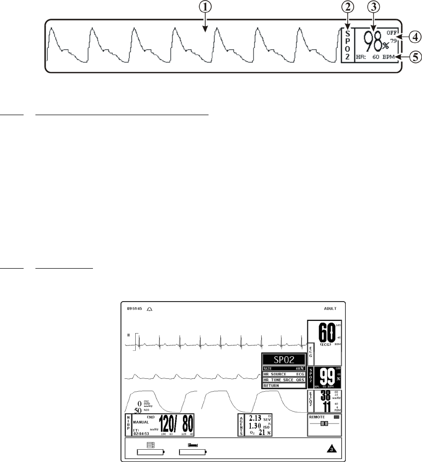
4-13
b. PROBE OFF. The sensor is not sensing or detecting the patient's pulse. There are two
possible causes of this, either the sensor is not detecting the pulse or the sensor is
receiving too much light to operate. Check the ambient lighting, if a light is shining
directly into the sensor, reposition the sensor to a darker area or cover the sensor to cut
down the light entering the sensor. Check the sensor cable connection for proper
connection. Try a different sensor.
c. HIGH LIGHT. There is too much light passing through the tissue at the present
sensor site. Move the sensor to an area with thicker tissue.
d. SEARCHING. The monitor is searching for a good pulse. Give the monitor time to
lock onto a good pulse.
e. LOW QUAL. The signal correlation between the red and infrared light channels is too
low for accurate saturation calculation. Contact Invivo Technical Service for further
assistance.
Figure 4-10. SpO2 Display
4.3.2 Associated Waveforms and Displays (See Figure 4-10) If the SpO2 is turned on the
waveform is displayed in Trace Location C and the numerical information in Box 2. The following is a
description of the items contained within the SpO2 Display:
a. SpO2 Waveform. (Item 1) The SpO2 Waveform is displayed in Trace Location C.
b. Icon Label. (Item 2) This label identifies the parameter numerics that are displayed
within this box. SpO2 is monitored using Box 3.
c. SpO2 Numeric. (Item 3) A numeric indication of the patient's SpO2 reading.
d. SpO2 High and Low Alarm Limits. (Item 4) A numeric indication of the settings of
the High and Low SpO2 Alarm Limits.
e. Heart Rate. (Item 5) Heart Rate Value derived from SpO2.
4.3.3 SpO2 Menu (See Figure 4-11) The menu for the SpO2 is brought up with the selection of the
SPO2 Menu-Select icon. This menu has a time-out feature. If no action is taken for approximately
60 seconds, the monitor will automatically return to the Normal Screen.
Figure 4-11. The SpO2 Menu

4-14
The following is a description of the SPO2 Menu options:
a. SIZE. (See Figure 4-12) Selecting this menu option provides the operator with the
ability to change the size of the SpO2 pulse waveform. The options are 10%, 20%,
40% (default), 60%, 80% and 100%.
Figure 4-12. The SpO2 SIZE Menu
b. HR SOURCE. Selecting this menu option allows the selection of the source to be used
for the heart-rate display in the ECG area. The options are AUTO, ECG (default), ART
(arterial pressure), SPO2 and NIBP.
This menu option is identical to, and interactive with, similarly named menu options
under ECG and NIBP.
c. HR TONE SRCE. Selecting this menu option selects the Heart Rate tone source. The
options are QRS, SPO2 and OFF (default). When the source is the QRS, the tone
sounds at the detection of QRS from the ECG parameter. When the source is the SpO2,
the tone sounds at the detection of the pulse from the SpO2 parameter.
The pulse tone is modulated by the SpO2 value. The pitch will be at the lowest
frequency when its value is at the low end of scale.
This menu option is identical to, and interactive with, the HR TONE SOURCE option
in the SOUND ADJUST and ECG Menus.
d. RETURN. Selecting this menu option will return the monitor to the Normal Screen.
4.3.4 Alarm Limits. Alarm Limits may be set two ways. To set the Alarm Limits for every available
parameter, from the Normal Screen (with no icons highlighted), press the ALARMS SCREEN Menu-
Select Key. To set the Alarm Limits for SpO2 only, highlight the SpO2 Icon and press the ALARMS
SCREEN Menu-Select Key to access the individual parameter Alarm Limits Box. The range of Alarm
Limits for SpO2 is 50 to 100%.
4.3.5 Trended Data. For complete information on the trending of patient SpO2 data, see Section 5:
Printing and Trending.
4.3.6 SpO2 Messages. The following is a list of messages that may be displayed during SpO2
monitoring:
NOTE
Invasive Pressure is not available with this system. If ART is selected as the HR SOURCE a
Warning box appears that informs the operator that this option is not available.
BAD PROBE The monitor has sensed a shorted or open connector in the sensor.
Contact Invivo Technical Service for further assistance.
HIGH LIGHT There is too much light passing through the tissue at the present
sensor site. Move the sensor to an area with thicker tissue.

4-15
4.4 End-tidal CO2 (EtCO2) Monitoring. The EtCO2 Menu is brought up (if this parameter is
turned on through the SETUPS Menu) with the EtCO2 Menu-Select Icon. The EtCO2 feature
provides side stream measurement of CO2 and mean N2O with a continuous real time CO2 Waveform
Display. This feature will perform an automatic zeroing at periodic intervals while continuously
performing pressure corrections. EtCO2 monitoring also provides Respiration Monitoring.
The following three secondary menus support the EtCO2 monitoring feature:
•RECORDER Menu. Used to select recorder functions and to set the recorder and
trace speed.
•ALARMS Menu. Used to set and/or disable the EtCO2 alarms. The range of
Alarm Limits for EtCO2 is 5 to 80 mmHg.
•EtCO2 Trend Menu. Used to setup and print Trended information.
4.4.1 Patient and Sampling Line Preparation. The accuracy of the data collected is greatly
influenced by the proper use, fitting and maintenance of the sampling tubing, moisture filters and
patient breathing apparatus.
LOW LIGHT The transmission of the light is partially blocked. The tissue at the
site may be too opaque and/or thick. If the sensor is positioned on the
finger, check the fingernails for nail polish, long fingernails and
artificial fingernails; remove fingernail polish completely, for
artificial nails: use a Multi-Site sensor at another location, and, for
long fingernails: either trim the nails or use a Multi-site sensor at
another location.
LOW QUAL The signal correlation between the red and infrared light channels is
too low for accurate saturation calculation. Contact Invivo Technical
Service for further assistance.
PROBE OFF The sensor is not sensing or detecting the patient's pulse. There are
two possible causes of this, either the sensor is not detecting the pulse
or the sensor is receiving too much light to operate. Check the
ambient lighting, if a light is shining directly into the sensor,
reposition the sensor to a darker area or cover the probe to cut down
the light entering the sensor. Check the sensor cable connection for
proper connection. Try a different sensor.
SEARCHING The monitor is searching for a good pulse. Give the monitor time to
lock onto a good pulse.
NO PROBE The monitor is not detecting a sensor connected. Check that the
sensor is securely connected to the monitor. Try a different sensor.
Hardware Failure The monitor has detected a hardware failure. Remove the system
from service immediately and refer it to Invivo qualifed service
personnel for repair. This monitor should not, for any patient that
requires accurate SpO2 measurement, ever be placed back into
service before the repair is performed.
Wrong Probe The monitor has detected a probe type that is not compatable with
this system. Replace the probe with an Invivo approved probe.
Remember to use only Invivo approved accessories with this
monitor.
CAUTION
Before using the EtCO2 analyzer, read the PRECAUTIONS and USER RESPONSIBILITIES
which follow the Table of Contents.
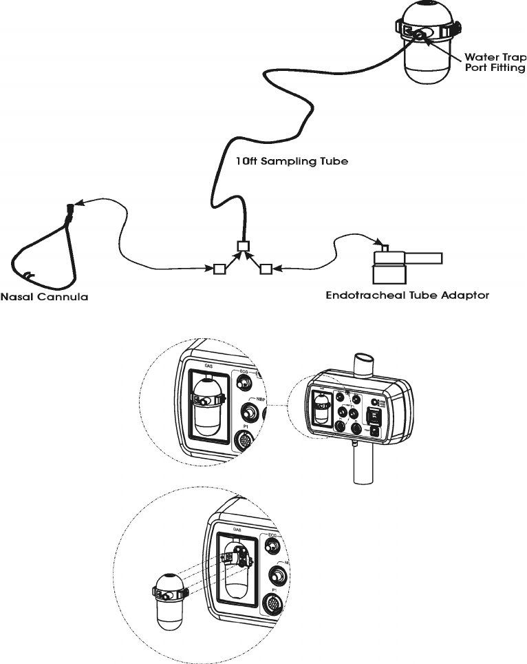
4-16
a. The patient sampling circuit (See Figure 4-13) consists of the sampling line and either
a sampling nasal cannula or a side stream adaptor connected to an endotracheal
connector. All fittings in the circuit are Luer-Lock type. All fittings should be fitted
together securely to keep them from separating during the procedure, and to ensure
proper sampling without the introduction of outside air. Loose fitting will result in
Gas measurement errors.
b. Nasal Cannula. The nasal cannula is of the “around-the-ear” type. Place the nasal
prongs gently inside the nose, loop the excess tubing over the patient's ears and then
down under the chin. The cannula may then be fitted by sliding the plastic ring up until
the cannula is secure and comfortable.
c. Endotracheal Adaptor. When using the endotracheal adaptor, attach the Nafion®
Dryer Line before attaching the endotracheal adaptor to the endotracheal tube. Take
great care not to dislodge or move the endotracheal tube when attaching the adaptor.
Figure 4-13. The Patient Sampling Circuit
Figure 4-14. Water Trap Installation Diagram
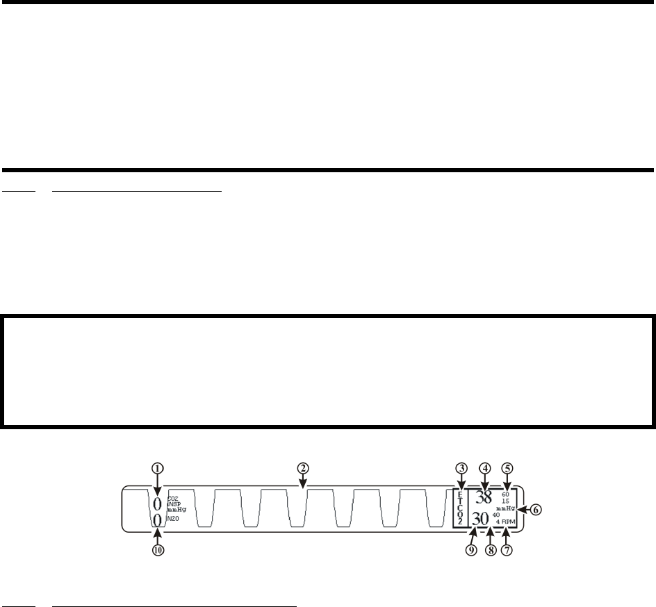
4-17
4.4.2 Water Trap Replacement. (See Figure 4-14) Remove the sample line from the Water Trap
port and perform the following to replace the Water Trap:
a. To remove the Water Trap: simultaneously press the two release tabs (located on the
left and right side of the trap near the top) and pull the Water Trap from the enclosure.
b. To install the Water Trap: line the trap up with the enclosure (the enclosure is shaped to
the Water Trap) and press it into place until there is an audible “click” from both of the
release tabs.
c. Attach sample line to Water Trap port.
Figure 4-15. The EtCO2 Display
4.4.3 Associated Waveforms and Displays (See Figure 4-15) EtCO2 information is displayed as a
waveform in Trace Location D and as numeric data in Box 4. The following is a description of the
items contained within the EtCO2 Display:
For best fit and compatibility, Invivo strongly recommends the use of the Invivo CO2 Sampling
Kit (Part No. 9010D), which contains all the above tubings and endotracheal tube adaptor.
a. Inspired CO2 Numeric. (Item 1) A numeric indication of the patient's Inspired CO2
reading.
b. Respiration Waveform. (Item 2) The EtCO2 derived Respiration Waveform is
displayed in Trace Location D.
c. Icon Label. (Item 3) This label identifies the parameter numerics that are displayed
within this box.
d. EtCO2 Numeric. (Item 4) A numeric indication of the patient's EtCO2 reading.
e. EtCO2 Alarm Limits. (Item 5) A numeric indication of the settings of the High (on
top in the example) and Low (bottom in the example) EtCO2 Alarm Limits.
f. Unit of Measurement. (Item 6) Displays the Unit of Measurement being used for
presentation of the EtCO2 numeric data.
CAUTION
Do not allow the tubing to become kinked so that the sample flow is reduced or cut off.
Be careful that the tubing remains clear of any table moving mechanisms which may kink or cut the
tubing.
Always discard the Water Trap when it becomes filled. Do not attempt to clean or reuse the Water
Trap. Accidental water ingress into the monitor can affect the Gas measurements.
Always inspect patient tubing after attachment to the monitor following the patient circuit’s
manufacturer’s recommendations.
WARNING
Always test sampling line adapter for a tight connection and proper operation before attaching to a
patient.
Overtightening the sampling line may damage the water trap. Tighten the sampling line no more
than 1/4 turn.
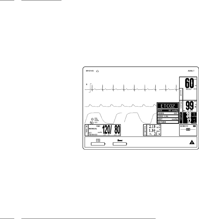
4-18
g. Unit of Measurement. (Item 7) Displays the Unit of Measurement being used for
presentation of the EtCO2 derived Respiration numeric data.
h. Respiration Alarm Limits. (Item 8) A numeric indication of the settings of the High
(on top in the example) and Low (bottom in the example) Respiration Alarm Limits
when derived from the EtCO2 module.
i. Respiration Numeric. (Item 9) A numeric indication of the patient's Respiration
reading derived from the EtCO2 module.
j. N2O Numeric. (Item 10) A numeric indication of the patient's N2O reading.
4.4.4 EtCO2 Menu. (See Figure 4-16) The menu for the EtCO2 is brought up with the selection of
the EtCO2 Menu-Select icon. This menu has a time-out feature. If no action is taken for
approximately 60 seconds, the monitor will automatically return to the Normal Screen.
The following is a description of the EtCO2 Menu options:
a. SIZE. Selecting this menu option brings up the SIZE Menu where the operator may
select 40, 60 or 80 mmHg for the Scale Size of the EtCO2 Waveform Display.
b. GRIDS. Selecting this menu option brings up the GRIDS Menu where the operator
may turn the EtCO2 Grids ON or OFF.
Figure 4-16. The EtCO2 Menu
c. ZERO CAL. Selecting this menu option causes the monitor to perform the Zero
Calibration routine.
d. UNIT. Selecting this menu options brings up the UNIT Menu where the operator may
toggle the monitor between mmHg and kPa.
e. RETURN. Selecting this menu option will return the monitor to the Normal Screen.
4.4.5 Calibration of CO2/N2O Measurement System The monitor will perform automatic Zero
Calibration cycles as part of its normal function. The Zero Calibration cycle is discussed below.
a. Zero Calibration Cycle. A Zero Calibration cycle consists of the realignment of the
Zero point. During this calibration, the monitor makes sure that a concentration of 0%
is measured when room air is flowing through its sample chamber. During a Zero
Calibration cycle the unit performs the following steps:
(1) Switches the input gas valve to the Zero Intake Port placed on the rear panel.
(2) Room air is absorbed through the Zero Intake Port and flushes the pneumatic
system for a few seconds.
(3) Once the channel readings have stabilized, a snapshot is taken and the Zero
point is realigned using these readings as a reference.
(4) The Input Gas Valve is then switched back to the normal position and the gas
being measured is given a few seconds to flush the pneumatic system to clear
out the room air.

4-19
(5) After the readings stabilize, the EtCO2 system begins it’s normal functioning
routine.
b. Automatic Zero Calibration Cycles. An automatic Zero Calibration cycle is
triggered when certain time intervals have passed since the monitor has completed its
warm-up cycle. The timetable for automatic Zero Calibration cycles is the following:
2, 4, 6, 8, 10, 20, 40 and 60 minutes. After the first hour since warm-up, the monitor
will perform a Zero Calibration cycle every hour. In addition, event-related Zero
Calibration cycles are triggered when certain variations are noticed in the input signals
(gases or temperatures). These events are:
(1) A variation of 10% in the concentration of N2O.
(2) A variation in the ambient temperature inside the unit box of 1°C.
(3) A change in the ID of the current anesthetic agent (if Anesthetic Agents feature
is available).
(4) A change in the concentration of the currently measured anesthetic agent by
2% volume (if Anesthetic Agents feature is available).
(5) A variation in the concentration of the currently measured anesthetic agent by
400% relative for concentrations in excess of 1% (if Anesthetic Agents feature
is available).
c. Operator Initiation of Zero Calibration. To manually initiate the Zero Calibration
Routine, perform the following procedure:
(1) Press the SETUP Control Key.
(2) Highlight the SERVICE (BIO-MED) menu option and then press the Rotary
Knob to select.
(3) Highlight the GAS CAL menu option and then press the Rotary Knob to select.
(4) Highlight the ZERO CAL menu option and then press the Rotary Knob to
initiate the Zero Calibration Routine.
This option is identical to the ZERO CAL menu option in the EtCO2 Menu.
4.4.6 Alarm Limits Alarm Limits may be set two ways. To set the Alarm Limits for every available
parameter, from the Normal Screen (with no icons highlighted), press the ALARMS SCREEN Menu-
Select Key. To set the Alarm Limits for EtCO2 only, highlight the EtCO2 Icon and press the
ALARMS SCREEN Menu-Select Key to access the individual parameter Alarm Limits Box. The
range of Alarm Limits for EtCO2 is 5 to 60 mmHg and Off for the Low Limit and 5 to 80 mmHg and
Off for the High Limit.
4.4.7 Trended Data For complete information on the trending of patient EtCO2 data, see Section 5:
Printing and Trending.
4.4.8 EtCO2 Messages The following is a list of messages that may be displayed during EtCO2
monitoring:
NOTE
To perform Zero Calibration, the monitor pulls ambient air through the rear panel CO2 Zero Intake
Port. The Calibration system assumes that the ambient air will contain normal amounts of trace
CO2. If this monitor is placed in an unventilated area that allows CO2 (from the rear panel CO2
Exhaust Port - if not connected to a Gas Scavenging System) to accumulate, the result could be
inaccurate Zeroing of the EtCO2 module and resulting inaccurate patient readings.
CO2 OCCLUSION The air lines have become blocked. Check exposed hose
for kinks and blockages. If blockage appears to be internal
to the unit, contact a Qualified Service Representative.
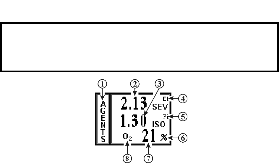
4-20
4.5 Anesthetic Agent/Oxygen Monitoring. (Optional) The Anesthesia Gas Sensor (AGS) is a
non-dispersive, single path Infra-Red spectrometer based upon a high stability IR sensor technology
known as Stabilized Thermopile Bridge (STB). Utilizing the STB technology, the Invivo AGS yields
high output, low noise and ultra stable gas measurements.
The following two secondary menus support the Anesthetic Agent/Oxygen monitoring
feature:
•RECORDER Menu. Used to select recorder functions and to set the recorder and
trace speed.
•ALARMS Menu. Used to set and/or disable the temperature alarms.
4.5.1 Patient and Tubing Preparation. Use only original Invivo sampling lines and accessories;
other sampling lines may cause inaccurate readings and malfunctions. Change sampling line and
airway adapter for each patient.
Figure 4-17. Anesthetic Agents Display
ETCO2: HW FAIL The EtCO2 has failed, contact a Qualified Service
Representative.
ETCO2 WARMING UP The EtCO2 is warming up in preparation for use. The
warmup cycle is approximately two (2) minutes.
NO CO2 CAL: STILL
WARMING
CO2 Calibration cannot initialize because the EtCO2
system has not completed warming up. (For non-Agent
EtCO2 only)
READJUSTING CO2
ZERO
The EtCO2 module is performing its automatic Zero
Adjustment Routine.
WARNING
Always test sampling line adapter for a tight connection and proper operation before attaching to a
patient.
Overtightening the sampling line may damage the water trap. Tighten the sampling line no more
than 1/4 turn.

4-21
4.5.2 Associated Displays. (See Figure 4-17) Anesthetic Agent information is only displayed as
numeric data. Agent data can be displayed in Boxes 7 through 10. The Agent identification and
measurement are individually performed on both inspired and expired gases. With any two mixtures
involving gases Sevoflurane and Isoflurane, the inspired primary anesthetic agent (the gas with the
highest concentration) is displayed with its ID and concentration in the Fi location of the Agent Icon
box. The expired primary anesthetic agent is displayed with its ID and concentration in the Et location
of the Agent Icon box. An alarm sounds and “MULTIPLE AGENTS” is displayed any time two or
more anesthetic agents are detected. If Halothane or Enflurane are involved in any mixture of
anesthetic agents, “---” may appear in the Fi and/or Et location while a pure inspired or expired gas is
displayed in its appropriate location. See Tables 4-1 and 4-2 for a complete description of the Agent
display during mixed Agent conditions.
The following is a description of the items contained within the Anesthetic Agent Display.
a. Icon Label. (Item 1) This label identifies the parameter numerics that are displayed
within this box.
b. Agent Expired Numeric. (Item 2) A numeric indication of the value of the gas being
expired.
c. Agent Inspired Numeric. (Item 3) A numeric indication of the value of the gas being
inspired.
d. Et. (Item 4) Indicates that the top row numeric is the End Tidal (expired) values of the
gas being monitored (with the designation of the gas located just below Et).
e. Fi. (Item 5) Indicates that the bottom row numeric is the fraction of inspired (Fi) values
of the gas being monitored (with the designation of the gas located just below Fi).
f. Unit of Measurement. (Item 6) Displays the Unit of Measurement being used for
presentation of the Anesthetic Agents and Oxygen numeric data (i.e. Percentage).
g. Oxygen Numeric. (Item 7) A numeric indication of the patient’s Oxygen
measurement.
h. O2. (Item 8) Indicates that the patient’s oxygen is being monitored in this row.

4-22
Table 4-1. Agent Display During Mixed Agent Conditions
Display
MULTIPLE
AGENTS
Message
Physical Gas
Sevoflurane, Isoflurane or any mixture of two
where the gas with the highest concentration is
considered primary.
Agent Display
Inspired
(Fi)
Expired
(Et)
Fi ID
% Inspired
Concentration
Et ID
%Expired
Concentration
No Agent 1 Agent 1 Agent 1 Agent 1
Yes Agent 1 Agent 2 Agent 1 Agent 2
Yes Agent 2 Agent 1 Agent 2 Agent 1
Yes Agent 1 - Primary
Agent 2 - Secondary
Agent 1 - Primary
Agent 2 - Secondary
Agent 1 Agent 1
Yes Agent 2 - Primary
Agent 1 - Secondary
Agent 1 - Primary
Agent 2 - Secondary
Agent 2 Agent 1
Yes Agent 2 - Primary
Agent 1 - Secondary
Agent 2 - Primary
Agent 1 - Secondary
Agent 2 Agent 2
Yes Agent 1 - Primary
Agent 2 - Secondary
Agent 1 Agent 1 Agent 1
Yes Agent 2 - Primary
Agent 1 - Secondary
Agent 1 Agent 2 Agent 1
Yes Agent 1 - Primary
Agent 2 - Secondary
Agent 2 Agent 1 Agent 2
Yes Agent 2 - Primary
Agent 1 - Secondary
Agent 2 Agent 2 Agent 2
Yes Agent 1 Agent 1 - Primary
Agent 2 - Secondary
Agent 1 Agent 1
No - - --- ---
Yes Agent 1 Agent 2 - Primary
Agent 1 - Secondary
Agent 1‘ Agent 2
Yes Agent 2 Agent 2 - Primary
Agent 1 - Secondary
Agent 2 Agent 2
Yes Agent 2 Agent 1 - Primary
Agent 2 - Secondary
Agent 2 Agent 1
No Agent 1 - Agent 1 ---
No - Agent 1 --- Agent 1
No Agent 2 - Agent 2 ---
No - Agent 2 --- Agent 2

4-23
Table 4-2. Agent Display During Mixed Agent Conditions
i. Anesthetic Agent Designation. (Items 4 and 5) Displays the identification of the gas
being monitored. The Agent Identifications are as follows:
(1) Halothane HAL
(2) Isoflurane ISO
(3) Sevoflurane SEV
4.5.3 Agent Menu. The Anesthetic Agent monitoring feature does not have a menu like the other
monitoring features on this monitor. Pressing the Rotary Knob while the AGENTS icon is highlighted
brings up a box which displays the Minimum Alveolar Concentration (MAC) values. 1 MAC Values
used to Calculate the displayed MAC are as follows: HAL=0.76%, ENF=1.68%, ISO=1.12%,
SEV=1.92%, DES=6.0% and N2O=100%.
Calculation of displayed MAC value: Cal. MAC = (EtN2O/1 MAC N2O) + (Et Agent/1 MAC Agent).
4.5.4 Gas Calibration. The monitor performs a Zero Calibration periodically and the operator may
also manually initiate a Zero Calibration cycle. There is a two (2) minute warmup period when Agents
is first turned on during which there is no monitoring. The entire warmup period is 20 minutes during
which the monitor will perform an automatic Zero Calibration at the two minute mark in the warmup
period, then will run again in the following sequence: 4, 6, 8, 10, 12, 14, 16, 18, 20, 40 and 60 minutes.
After the 60 minutes has expired the Zero Calibration will run once an hour, or whenever an anesthetic
agent change is detected.
Display
MULTIPLE
AGENTS
Message
Physical Gas
Halothane and involved mixes. Agent Display
Inspired
(Fi)
Expired
(Et)
Fi ID
% Inspired
Concentration
Et ID
%Expired
Concentration
No Agent 1 Agent 1 Agent 1 Agent 1
Yes Agent 1 Agent 2 Agent 1 ---
Yes Agent 1 Mix Agent 1 ---
Yes Mix Agent 2 --- Agent 2
Yes Mix Mix --- ---
No Agent 1 - Agent 1 ---
Yes Mix - --- ---
No - Agent 2 --- Agent 2
Yes - Mix --- ---
No - - --- ---
WARNING
Minimum Alveolar Concentration (MAC) values are empirical and are not absolute values. Invivo's
AGS MAC values correspond to those of healthy adults and cannot be applied to children. Age and
other individual factors influencing the behavior of volatile agents are not taken into account.
NOTE
Mixed concentration of Agents are not included in the MAC calculations.

4-24
On the WPU only, if the Agents option is run over a continuous 12 hour period with an O2
concentration of 22% or greater there is a Warning Box that will appear to alert the operator that a
one (1) minute O2 Calibration sequence must be run. The Warning Box will offer the operator a
Yes/No option of running the one (1) minute O2 Calibration sequence, if the operator selects NO,
the message will reappear in 30 minutes. An O2 Calibration message will also appear if the O2
Sensor detects a reading greater than 103% and whenever an O2 sensor is inserted into the back of
the monitor (if the monitor has completed its CO2 zeroing process).
a. Anesthetic Agent Quality Control (QC) Check. Perform a QC Check at least once a
month, or whenever Agent accuracy is questionable.
(1) Before performing the Anesthetic Agent QC Check, the monitor must be at a
stable operating temperature. The monitor must be turned on, with EtCO2 and
Agent parameters active, for a minimum of 45 minutes before the QC check is
performed.
(2) Each QC Check Gas can comes with a nozzle and tubing with a “T” fitting for
connecting to the gas (EtCO2) input port in the monitors front panel.
(3) See the Accessories List in the Table of Contents Section of this manual for
selection of the QC Check Gas for the Anesthetic Agents you are using.
(4) If required, Agent Span Calibration can be performed. Refer to service
instructions for this procedure.
4.5.5 Alarm Limits. The Agent Alarm Limits are set by selecting the GAS ALARMS menu option
in the ALARMS Menu, which is accessed by pressing the ALARMS SCREEN Menu-Select Key, or
by highlighting the AGENT Icon and pressing the ALARMS SCREEN Menu-Select Key to access
the ALARMS Menu.
4.5.6 Trended Data. For complete information on the trending of patient Agent data, see Section 5:
Printing and Trending.
4.5.7 Agent/O2 Messages. The following messages are used for Anesthetic Agent/O2 monitoring:
NOTE
Patient Waste Gas Removal. Continuous exposure of Health Care workers to waste anesthetic
gases (including halogenated agents and nitrous oxide) is not recommended. Always attach the
waste gas connection on the rear of the monitor to the room's gas evacuation system. Avoid venting
any waste anesthetic gas directly into the room air as exposure to waste anesthetic gases above the
recommended OHSA limits could result.
Flashing Insp CO2 Numeric (Fixed CO2 Rebreathing Alarm) The Inspired CO2
numeric turns red and flashes with Alarm sound. Occurs
when Inspired CO2 is greater than 25 mmHg. This
alarm is a fixed, non-adjustable alarm.
Flashing N2O Numeric (Fixed N2O Alarm) N2O numeric turns red and flashes
with Alarm sound. Occurs when N2O is greater than
80%. This alarm is a fixed, non-adjustable alarm.
EtCO2 WARMING UP Message flashing red. Occurs during CO2/Anesthesia
Gas Sensor warmup.
CO2 OCCLUSION Message flashing red with Alarm sound. Occurs when
sample line is occluded.
MULTIPLE AGENTS Message flashes red with Alarm sound. Occurs when
more than one Anesthetic Agent is identified.

4-25
4.5.8 Oxygen Monitoring. This parameter is part of the EtCO2/Agents module. That is, it uses the
exhaust air from the EtCO2/Agents module as its imput and its air flow is controlled by the pneumatic
hardware in the EtCO2/Agents hardware module. The O2 value is displayed in the Anesthetic Agents
Display (See Figure 4-17).
a. Oxygen Module Calibration. The O2 module is calibrated automatically upon
power-up (as described in the NOTE above). Thereafter, is calibrated everytime an O2
CAL is initiated by the user (See the GAS CAL menu (SETUPS/SERVICE(BIO-
MED)/GAS CAL) for further information). The operator is prompted that an O2
calibration is required if O2 remains above 22% for 12 hours and, since O2 calibration
requires one (1) minute, the operator may reject the calibration request by answering
NO to the YES/NO prompt. If NO is selected the operator is then prompted every 30
minutes until the O2 calibration is initiated by a YES response. Calibration is done
based on the assumption that the ambient O2 concentration, sensed at the EtCO2
Zeroing Port, is 20.9% (during calibration, the patient GAS Input Port must not be
connected to an oxygen source).
b. Oxygen Sensor Replacement. The Oxygen Sensor (Invivo Part Number 9445) is
located on the rear of the WPU near the DCU mounting pole. The Oxygen Sensor has
an expected life of greater than six months with expected life inversely proportional to
changes in Oxygen Concentration, Temperature and Pressure. The Oxygen Sensor
begins aging immediately upon the opening of the package and should, therefore, not
be opened until ready for use. The Oxygen Sensor should be replaced periodically as
part of routine maintenance. This monitor cannot be connected to the scavenge gas
system without the Oxygen Sensor installed, never operate without the monitor
connected to the scavenge gas system. Always operate the monitor with the Oxygen
Sensor installed.
(1) Oxygen Sensor Replacement Instructions. Replace the Oxygen Sensor as
follows:
(a) Unplug the adapter cable from the Oxygen Sensor.
(b) Unscrew the Oxygen Sensor by turning it counterclockwise until it
comes free.
(c) Open bag containing new disposable Oxygen Sensor (IRI #9445).
(d) Screw Oxygen Sensor into threaded port on Adaptor Subassembly.
(e) Plug adapter cable assembly into the Oxygen Sensor.
READJUSTING CO2
ZERO
Message flashing red. Occurs during CO2/Anesthesia
Gas Sensor zeroing operation.
REPLACE O2 SENSOR The Oxygen Sensor is bad and must be replaced.
NOTE
When the Agents parameter is turned on the O2 sensor is automatically calibrated during initial
warm up of the EtCO2/Agent Module. During this time the patient GAS input port must not be
connected to an oxygen source as the monitor requires 20.9% Oxygen (room air) for automatic
calibration.

5-1
SECTION 5
RECORDING AND TRENDING
5.0 RECORDING AND TRENDING.
5.1 Introduction. The 3160 MRI Physiological Monitoring System thermal array strip
recorder can record one or two waveforms (as selected from the RECORDER Menu). The recorder
prints patient parameters on the edge of the strip chart and ends with a “snapshot” patient data report.
The Recorder option provides the following features:
• Selection of the traces to be sent to the recorder.
• High frequency response (Single = 800 samples/second at 25 mm/second speed
and Dual = 400 samples/second at 25 mm/second speed) with a bandwidth of 100
Hz.
• Transmitting a calibration waveform to the recorder.
• Total control over the Recorder mode (OFF/AUTO/RUN).
• Selection of patient data report for printing.
• Selection of data collection intervals for report.
• 0 to 16 seconds of trace delay in four increments.
• Selection of 25 or 50 mm/second recorder speed (and screen trace speed).
• The paper record is automatically annotated with the alphanumeric indication of
date, time, trace delay, paper speed, scales, lead configuration, mode, heart rate,
NIBP (which displays systolic, diastolic and mean blood pressures), respiration
rate, EtCO2, SpO2 and Agent Gas ID for expired and inspired breath phases.
• If an active alarm limit is violated, the numeric value of the corresponding
parameter is printed at the beginning of the automatically activated record.
• The recorder uses non-grid thermal paper.
5.1.1 Record Key. The RECORD key starts/stops the Recorder upon operator demand. If left
running the recorder will continue to supply hard copy output for approximately 25 seconds before it
automatically shuts off.
5.2 The RECORDER Menu. The RECORDER Menu provides adjustments that will allow
this monitor to supply concise and up to date printouts suitable to a wide variety of situations. Pressing
the RECORDER SETUP Menu-Select key brings up the RECORDER Menu (See Figure 5-1). If
the recorder is not installed, the message “RECORDER OPTION NOT INSTALLED” is displayed
on the screen. This menu has a time-out feature. If no action is taken for approximately 60 seconds,
the monitor will automatically return to the Normal Screen.
The following is a description of the options in the RECORDER Menu:
a. TRACE 1. Selecting this menu option allows the selection of the first trace to be
output to the recorder. The options [depending on currently installed parameters] are
ECG1 (default), SPO2 and RESP(CO2). If TRACE 2 is off, TRACE 1 is output to the
recorder using the full 40 mm width of the printout.
b. TRACE 2. Selecting this menu option allows the selection of the second trace to be
output to the recorder. The options [depending on the currently installed parameters]
are OFF (default), ECG1, SPO2 and RESP(CO2).
NOTE
The Recorder unit is only available on the DCU.
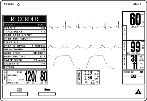
5-2
Figure 5-1. The RECORDER Menu
c. TRACE DELAY. Selecting this menu option allows the selection of the time delay for
the trace data being sent to the recorder. The options are 0, 4 (default), 8 and 16
seconds.
d. PRINT DATA REPORT. Selecting this menu option activates the recorder to print a
patient data report (in tabular form) of up to 60 stored patient parameter readings stored
in the time interval preselected by the DATA INTERVAL menu option in this menu.
Only those parameters which have been turned on will be printed.
(1) The Data Report printout consists of the updates (updated every four minutes)
of the patient parameters (that are on during the data storage time) up to 60
measurements. The current date and the time of the recording are clearly
marked on the left of the printout.
(2) If a parameter is off during any portion of the data storage period, the message
`---/---' shall be printed in place of its value.
(3) The Data Report printout ends with a lined area for writing in the ID/CASE
number, the Patient's Name and the Operator Comments.
e. PRINT NIBP REPORT. Selecting this menu option activates the recorder to print the
NIBP report, with the last 48 NIBP readings in tabular form (6 readings per page).
f. CLEAR ALL. Pressing this function key erases all data stored for and the data report
in the monitor. When first pressed, a YES/NO Menu selection box appears that
requires an affirmative operator response before the stored data is cleared. The
operation of this function key requires confirmation by the user.
g. DATA INTERVAL. Selecting this menu option selects the data interval (1 - 60
minutes) for stored patient parameter readings to be printed in the Data Report
(activated by pressing the PRINT DATA REPORT menu option in this menu). The
options (in minutes) are 1 through 10 (3 being the default), 12, 15, 18, 24, 30 and 60.
The first data stored occurs either at power up, or 2 seconds after a new interval is
selected.
h. OFF/AUTO/RUN. Selecting this menu option allows the switching of the mode of the
Recorder. The options are OFF, AUTO and RUN. The following is an explanation of
the possible selections:
(1) OFF. Switches the Recorder Auto Mode OFF (the recorder may be activated
by pressing the RECORD Control Key.
5-3
(2) AUTO. If AUTO is selected, violation of an alarm limit for HR, NIBP, EtCO2
and SpO2 automatically activates the recorder trace and writes ECG Trace A.
In addition to ECG Trace A, a second trace will be written below it when the
parameter is in a trace location. The priority of the second trace recording is
RESP(CO2). SpO2 is written as the second trace recording when its alarm
limit is in violation and is the only other parameter in a trace location.
(a) The recording continues for 20 seconds or until the recorder is
deactivated by pressing the RECORD key or by changing the
Recorder Auto Mode to Off.
(3) RUN. RUN activates the recorder and prints the traces which have been
selected.
i. AUTO STRIP. Selecting this menu option allows the Automatic Report feature of the
Recorder to be switched On and Off. The options are DISABLED, ENABLED and
RETURN. The following is a description of the possible selections:
(1) DISABLED. Selecting this menu option will turn the Automatic Report
Feature OFF.
(2) ENABLED. Selecting this menu option will turn the Automatic Report
Feature ON.
(3) RETURN. Selecting the menu option will return the monitor to the
RECORDER Menu.
j. AUTO RUN TIME. Selecting this menu option brings up the AUTO RUN TIME
Menu where the operator can select the Automatic Strip Run Time. The options are 8,
12, 16, 20 and 30 seconds.
k. SWEEP SPEED. This menu option switches the recorder and the screen trace speed
between 25 and 50 mm/second.
l. CALIBRATE. Selecting this menu option opens the CALIBRATE Menu. This menu
option is identical to and interactive with the calibrate option in the ECG Menu. The
following options are available in the CALIBRATE Menu:
(1) OFF. Selecting this menu option turns the Calibration feature OFF.
(2) RECORDER. Selecting this menu option sends a 1mV pulse calibration
waveform to the ECG Vital Sign and will also be the ECG waveform printed
by the recorder if so configured. The message CAL is displayed over the ECG
waveform on the screen.
(3) ECG. Selecting this menu option sends a 2mV peak to peak (1mV peak)
calibration signal to the ECG vital sign and will also be the ECG waveform
printed by the recorder if so configured. The message CAL is displayed over
the ECG waveform on the screen. It is important to note that this is a hardware
generated calibration waveform and originates as a square wave.
(4) RETURN. Selecting this menu option closes the CALIBRATE Menu.
m. RETURN. Selecting this menu option will return the monitor to the Normal Screen.
5.3 Recording Charts. This monitor will print four different types of charts upon operator
demand. The four types are Strip Chart, Tabular Chart, Trend Chart and System Data Report. The
Sweep Speed of the printout may be set to 25 mm/second or 50 mm/second with the slower speed (25
mm/second) presenting the most data on a Strip Chart. Strip Charts, Tabular Charts and System Data
Reports are discussed below (Trend Charts are discussed in paragraph 5.5):
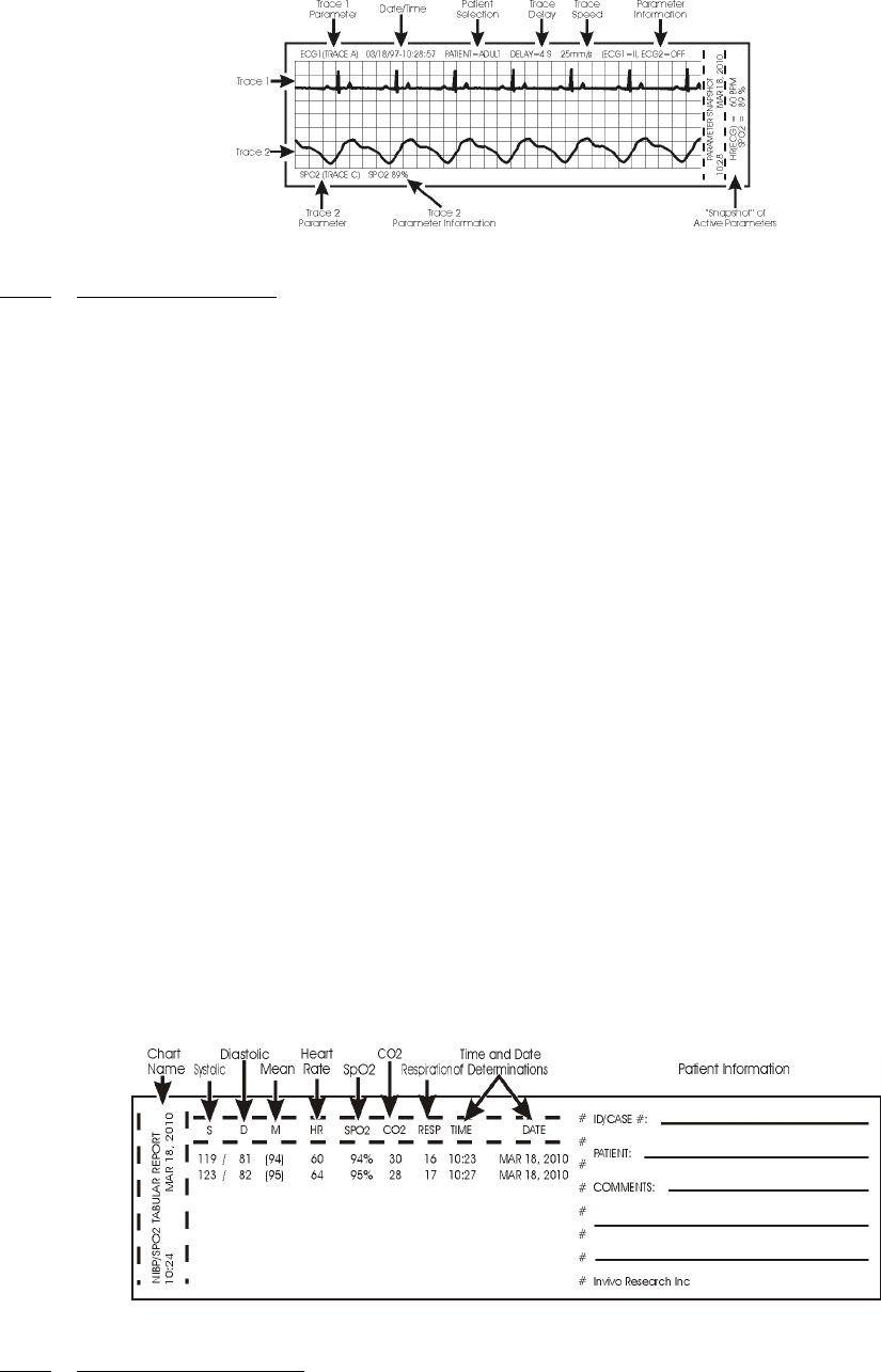
5-4
Figure 5-2. Sample Strip Chart
5.3.1 Strip Chart Record. (See Figure 5-2) The Strip Chart may be configured to contain one or
two parameter waveforms and also contains the numerical value of every active parameter as well as a
“Parameter Snapshot” of the current values of every active parameter at the end of the printout strip.
a. Setting Up the Strip Chart. Perform the following procedure to configure the Strip
Chart to the appropriate application:
(1) Press the RECORDER SETUP Menu-Select Key.
(2) To change Trace 1, which is defaulted to ECG1: press the Rotary Knob,
highlight the desired parameter and press the Rotary Knob to accept the new
selection.
(3) To change Trace 2, which is defaulted to OFF: highlight Trace 2 then press the
Rotary Knob, highlight the desired parameter and press the Rotary Knob to
accept the new selection.
(4) To set the Trace Delay, which is defaulted to 4 seconds: highlight Trace Delay
then press the Rotary Knob, highlight the desired delay (the options are 0, 4, 8
and 16 seconds) and press the Rotary Knob to accept the new selection.
(5) To set the monitor to provide a Strip Chart automatically, perform the
following:
(a) Select the desired time between automatic strips by highlighting the
Data Interval menu selection, pressing the Rotary Knob, highlighting
the desired time interval and pressing the Rotary Knob to accept the
selection.
(b) Set the Auto Strip to On by highlighting the Auto Strip menu selection,
pressing the Rotary Knob, highlighting Enabled and pressing the
Rotary Knob to accept the selection.
(6) To manually print a Strip Chart, press the RECORD control key.
Figure 5-3. Sample Tabular Chart
5.3.2 Tabular Chart Record. (See Figure 5-3) The NIBP/SpO2 Tabular Report provides a
hardcopy printout of the numerical indications of NIBP, Heart Rate, SpO2, CO2 and Respiration along
with the date and time of the determination.
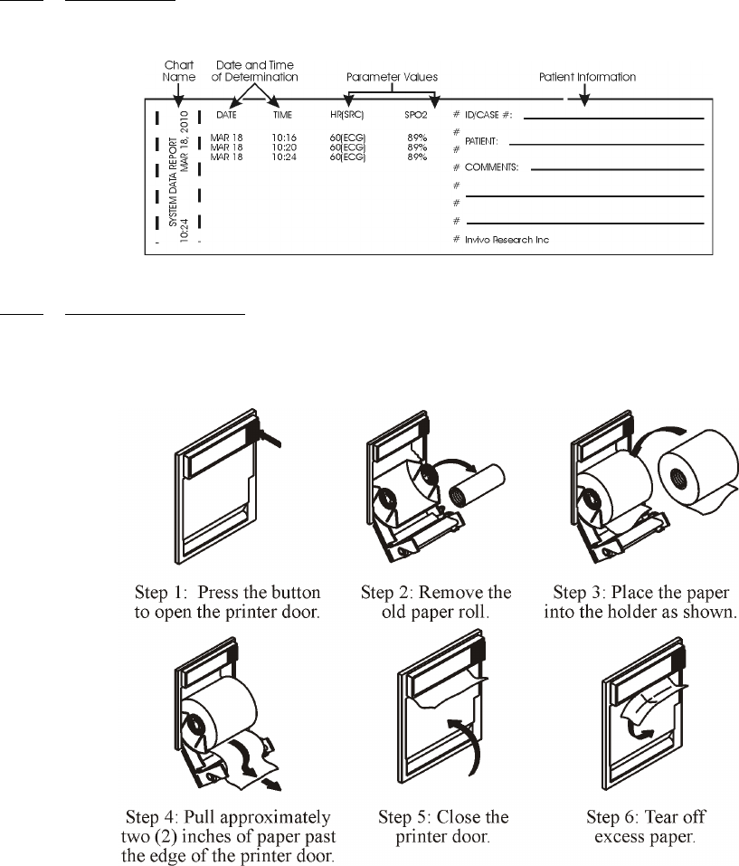
5-5
5.3.3 Trend Chart. Trend Charts may be printed for every parameter being monitored. To print an
individual trend chart, first highlight the icon of the parameter to be printed then press the Trends
Menu-Select key and select the RECORD menu option.
Figure 5-4. System Data Report
5.3.4 System Data Report. (See Figure 5-4) The System Data Report provides a hardcopy printout
of the numerical indications of all the active patient parameters along with the date and time of the
determination.
5.4 Loading Recorder Paper. Perform the procedure in Figure 5-5 to load the recorder paper.
Figure 5-5. Loading the Recorder Paper
5.5 Trending Feature. The Trend Feature may be operated to graph Multiple or Individual
Trends. Pressing the TRENDS Menu-Select Key, while in the Normal Screen, will bring up the
HISTORY Menu (See Figure 5-6). Pressing it while any Patient Parameter is highlighted will bring
up the Trend Menu for the Selected Patient Parameter. The 3160 Vital Signs Monitoring System
automatically stores the parameter trend information for the heart rate, NIBP, SpO2, EtCO2 and
Respiration. There is also an operational key, CLEAR TRENDS, on the monitor front panel that
allows the operator to clear all trends without bringing up any of the TREND Menus.

5-6
Figure 5-6. The HISTORY Menu
5.5.1 HISTORY Menu Options. The HISTORY Screen is a Tabular Listing of a patient's NIBP
determinations. The menu provides the option to move from page to page and to print all or part of the
History File. The following is a description of the options available in the HISTORY Menu:
a. PRT ALL. Selecting this menu item will print a complete NIBP History File.
b. PRT PAGE. Selecting this menu item will print the NIBP History File page that the
screen is currently at.
c. PREV PAGE. Selecting this menu item will change the display to the previous page
of the NIBP History File.
d. NEXT PAGE. Selecting this menu item will change the display to the next page of the
NIBP History File.
e. CLEAR ALL. Selecting this menu item will clear all the data from the NIBP History
File.
f. RETURN. Selecting this menu item will return the monitor to the Normal Screen.
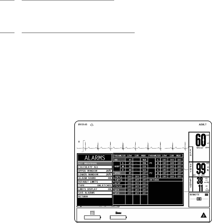
6-1
SECTION 6
ALARMS
6.0 ALARMS.
6.1 Introduction. The 3160 MRI Physiological Monitoring System permits user access to
every parameter alarm with a single select key. Alarm Limits may be turned on, adjusted (manually or
automatically) or turned off in the ALARMS Menu. Individual parameter alarms may also be turned
on and/or adjusted by highlighting the parameter icon and pressing the ALARMS SCREEN Menu-
Select key.
• The 3160 MRI Physiological Monitoring System may be set to give visual alarm
signals only (Alarm Limits set, but Alarm Sound off), or both visual and audible
signals (Alarm Limits set, with Alarm Sound on).
• All settings in the ALARMS Menu, except the Alarm Sound On/Off and Sound
Mode, can be stored and recalled.
6.2 Alarm Limits. The Alarm Limits may be set either manually or automatically. The 3160
MRI Physiological Monitoring System provides access to parameter Alarm Limits through a menu
accessed with the ALARMS SCREEN Menu-Select Key. Alarm Limits may be turned on, adjusted
(manually or automatically) or turned off in the ALARMS Menu.
6.2.1 Default (Pre-Set) Alarm Limits. This monitor will automatically set all the Alarm Limits to
Default settings upon monitor power up. Table 6-1 provides a listing of Factory Default Settings; it is
important to note that Table 6-1 will not represent the Default Values of your monitor if the Default
Values are selected by the User.
6.2.2 Range of High and Low Alarm Limits. Each patient parameter has a LOW and HIGH
Alarm Limit value position as indicated by numerics in the LOW and HIGH columns of Table 6-2.
The Alarm Limits displayed in this menu may be changed manually or automatically using the rotary
knob, after the patient parameter is selected. If a parameter has been turned off from the SETUPS
Menu, then its LOW and HIGH positions will be off on this menu.
6.3 Alarm Setup. Pressing the ALARMS SCREEN Menu-Select Key while in the normal
monitoring mode (Normal Screen displayed) with no icons highlighted will bring up the ALARMS
Menu (See Figure 6-1).
Figure 6-1. The ALARMS Menu
NOTE
The Alarm System automatically prevents the crossover of High and Low Limit settings.
6-2
This menu has the following menu options associated with it:
a. SET INDIVIDUAL. Selecting this menu option allows the operator to adjust
individual Alarm Limits. Once this menu option is selected, turning the knob will
allow the operator to scroll through the individual HIGH and LOW Alarm Limits for
manual modification. Once the limit to be modified is highlighted, pressing the knob
selects the limit and turning the knob changes the value. When the desired setting is
shown in the window, pressing the knob again will make the change effective and
return to scrolling through the individual HIGH and LOW Alarm Limits.
b. CALCULATE ALL. Selecting this menu option causes the monitor to calculate new
alarm limit values on all active parameters at once. The calculations are as described
under UPPER WINDOW and LOWER WINDOW menu options.
c. UPPER WINDOW. Selecting this menu option selects the percent value used in
calculating the HIGH Alarm Limits with the CALCULATE ALL menu option. The
menu options are 5%, 10%, 15%, 20% (default), or 30%. The monitor uses the current
value of the parameter and brackets it with the percentages set by this menu option and
the LOWER WINDOW menu option.
(1) For example, if the patient's heart rate is 60, and both percentages have been set
to 10%, activating CALCULATE ALL menu option will set the LOW Alarm
Limit to 54 and the HIGH to 66 (plus and minus 10 percent of the current heart
rate). Corresponding calculations would be used on each of the other active
patient parameters to set their LOW and HIGH values.
(2) The following exception applies:
• If the value being monitored from the patient is so high or low that
it would exceed the range of 3160 MRI Physiological Monitoring
System Alarm Limits (see below), the LOW or HIGH value is set to
the highest or lowest Alarm Limit for that parameter.
d. LOWER WINDOW. Selecting this menu option selects the percent value that is used
in calculating the LOW Alarm Limits with the CALCULATE ALL menu option. The
menu options are 5%, 10%, 15%, 20% (default), or 30%. The monitor uses the current
value of the parameter and brackets it with the percentages set by this menu option and
the UPPER WINDOW menu option.
(1) For example, if the patient's heart rate is 60, and both percentage have been set
to 10%, activating CALCULATE ALL would set the LOW Alarm Limit to 54
and the HIGH to 66 (plus and minus 10 percent of the current heart rate).
Corresponding calculations would be used on each of the other active patient
parameters to set their LOW and HIGH values.
The following exceptions apply:
• If the value being monitored from the patient is so high or low that
it would exceed the range of 3160 MRI Physiological Monitoring
System Alarm Limits (see below), the LOW or HIGH value is set to
the highest or lowest Alarm Limit for that parameter.
e. ALARM SOUND. Selecting this menu option will turn the alarm sound on/off. When
turned off, an “X” appears in the bell symbol on the screen and the bell symbol in the
menu indicating that the alarm sound has been disabled. This menu option is identical
to, and interactive with, the ALARMS menu option in the SOUND ADJUST Menu.
f. DEFAULT LIMITS. Selecting this menu option causes the monitor to automatically
set the LOW and HIGH Alarm Limits for all parameters at once based on the system
defaults (See Default Limits in Appendix A or Table 6-1 for a listing of the System
Default Values).
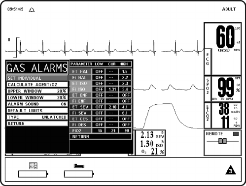
6-3
g. TYPE. Selecting this menu option will select whether the audio and visual alarms are
latched or unlatched (see definitions below).
(1) UNLATCHED. The Alarm Tone stops if the violated parameter returns to
within its limits, or the ALARM SILENCE key is pressed.
(2) LATCHED. The Alarm Tone will cease only when the ALARM SILENCE
key is pressed, even if the violating parameter has returned to within its limits.
h. LIMITS DISPLAY. Selecting this menu option will select whether or not the Alarm
Limits are displayed next to the parameter value in the Normal Screen. The default is
ON.
Figure 6-2. GAS ALARMS (Anesthetic Agents Alarm Limit) Menu
i. GAS ALARMS. Selecting this menu option will bring up the GAS ALARMS
(Anesthetic Agent Alarm Limits) Menu (See Figure 6-2). All the Alarm Limits
associated with the Anesthetic Agent System are adjusted in this menu. The following
is a description of the GAS ALARMS Menu:
This menu has the following menu options associated with it:
(1) SET INDIVIDUAL. Selecting this menu option allows the operator to adjust
individual Anesthetic Agent Alarm Limits. Once this menu option is selected,
turning the knob will allow the operator to scroll through the individual Agent
Alarm Limits for manual modification. Once the limit to be modified is
highlighted, pressing the knob selects the limit and turning the knob changes
the value. When the desired setting is shown in the window, pressing the knob
again will make the change effective and return to scrolling through the
individual Agent Alarm Limits.
(2) CALCULATE AGENT/O2. Selecting this menu option causes the monitor
to calculate new alarm limit values on all active Agent and O2 settings at once.
The calculations are as described under UPPER WINDOW and LOWER
WINDOW menu options.
(3) UPPER WINDOW. Selecting this menu option selects the percent value used
in calculating the HIGH Alarm Limits with the CALCULATE AGENT/O2
menu option. The menu options are 5%, 10%, 15%, 20% (default), or 30%.
The monitor uses the current value of the parameter and brackets it with the
percentages set by this menu option and the LOWER WINDOW menu option.

6-4
(4) LOWER WINDOW. Selecting this menu option selects the percent value that
is used in calculating the LOW Alarm Limits with the CALCULATE
AGENT/O2 menu option. The menu options are 5%, 10%, 15%, 20%
(default), or 30%. The monitor uses the current value of the parameter and
brackets it with the percentages set by this menu option and the UPPER
WINDOW menu option.
(5) ALARM SOUND. Selecting this menu option will turn the alarm sound on/
off. When turned off, an “X” appears in the bell symbol on the screen and the
bell symbol in the menu indicating that the alarm sound has been disabled. This
menu option is identical to, and interactive with, the ALARMS menu option in
the SOUND ADJUST Menu.
(6) DEFAULT LIMITS. Selecting this menu option causes the monitor to
automatically set the LOW and HIGH Alarm Limits for all parameters at once
based on the system defaults (See Default Limits in Appendix A or Table 6-1
for a listing of the System Default Values).
(7) TYPE. Selecting this menu option provides the operator the option to select
whether the audio and visual alarms are latched or unlatched (see definitions
below).
(a) UNLATCHED. The Alarm Tone stops if the violated parameter
returns to within its limits, or the ALARM SILENCE key is pressed.
(b) LATCHED. The Alarm Tone will cease only when the ALARM
SILENCE key is pressed, even if the violating parameter has returned
to within its limits.
(8) RETURN. Selecting this menu option will return the monitor to the Normal
Screen.
j. RETURN. Selecting this menu option will return the monitor to the Normal Screen.
6.3.1 Parameter Alarms Status Screen. While in the Alarms Screen, the Parameter Alarms Status
Screen is displayed to the right of the ALARMS Menu. This screen provides the operator with the
Low and High Alarm Limit Setting along with the Current Measurement value. By using the SET
INDIVIDUAL menu option with the Rotary Knob, the operator may adjust all the available parameter
limit settings.
6.4 Turning Alarms Off on Individual Parameters. Alarms may be set to OFF by pressing
the ALARMS SCREEN menu select key, selecting the SET INDIVIDUAL menu option and then
scrolling to the desired parameter to select it and turn it OFF.
6.5 Alarm Violations. An active Alarm Limit is violated when a patient parameter either
exceeds its HIGH setting or goes below its LOW setting. The alarm system's exact reaction depends on
the settings described in the remainder of this section, but, in general, all alarms operate as follows:
a. The numerics and trace (if displayed) of the violated parameter flash red on the screen.
b. The Alarm Tone on the DCU sounds, if it is enabled.
c. The numerics continue to flash while the parameter violates its Alarm Limit, even after
the Alarm Tone has been silenced by pressing the ALARM SILENCE key.
d. If the Printer is in the AUTO mode, it begins recording. For further information, see
Section 5.
WARNING
Alarm Limits can be set to a wide range including Off. It is the responsibility of the operator of this
monitor to ensure that Alarm Limit values appropriate to each particular patient are established and
set.

6-5
e. The numerics stop flashing after the parameter returns to within its Alarm Limits. If the
alarm system has been set to LATCHED, the numeric continues to flash after the
parameter returns to within its Alarm Limits, until the ALARM SILENCE control
key is pressed.
f. The numerics of the violated parameter flash on the screen and the audible alarm, once
silenced, will not sound again until after the alarm condition has been corrected. Only a
second (different) parameter alarm will cause the alarm sound to reactivate.
6.6 Adjusting the Alarm Tone Volume The Alarm Tone is adjusted in the SOUND ADJUST
Menu, which is accessed by selecting the SOUND ADJUST menu option in the SETUPS Menu.
6.6.1 Disabling the Alarm Tone The Alarm Tone may be disabled permanently in the ALARMS
Menu or it may be disabled temporarily by pressing the ALARM SILENCE control key.
a. The ALARM SILENCE control key has four functions as follows:
(1) WITH UNLATCHED ALARMS. If the alarm system has been set to
UNLATCHED in the ALARMS menu and an Alarm Limit is violated:
• It silences the alarm tone when an active Alarm Limit has been
violated.
WHILE THE PARAMETER CONTINUES TO VIOLATE ITS LIMITS:
• The numeric of the violated parameter will continue to flash on the
screen.
(2) WITH LATCHED ALARMS. If the alarm system has been set to
LATCHED in the ALARMS menu and an alarm is violated:
WHILE THE PARAMETER CONTINUES TO VIOLATE ITS LIMITS:
• It will silence the Alarm Tone.
• The numeric will continue to flash, even after the parameter returns
to within its Alarm Limits.
WHEN THE PARAMETER GOES BACK WITHIN LIMITS:
• It will silence the Alarm Tone, stops the numeric from flashing and
puts the Alarm System into the Alarm Hold mode.
WHEN THE ALARM HAS BEEN SILENCED AND THE PARAMETER
RETURNS TO WITHIN LIMITS:
• Pressing ALARM SILENCE will stop the numeric from flashing
and puts the Alarm System into the Alarm Hold mode.
NOTE
The Alarm Tone only applies to the DCU, there is no speaker on the WPU.
WARNING
Once an alarm condition has been silenced it will not sound again for any reason as long as that
alarm condition continues. For example, if a patients Heart Rate drops below the set limit and that
alarm is silenced, the alarm will never sound that condition again unless the Heart Rate returns to
within limits and then drops below the limit again.
6-6
(3) ALARM SILENCE. When the monitor goes into Alarm, pressing the
ALARM SILENCE control key silences the Alarm Tone for the current alarm
only. While the monitor is in the Silence mode, the letter “S” is displayed
within the Alarm Status Symbol (Alarm “Bell”), the Alarm Bell flashes and the
text “Alarm Silenced” is displayed in the middle of the display screen. If any of
the silenced alarm conditions return to acceptable limits, the monitor will
respond according to the above described Latched and or Unlatched operation.
If a new alarm occurs after the Silence mode is entered, the monitor will sound
the Alarm Tone for the new alarm. Pressing the ALARM SILENCE control
key a second time (after entering the Silence mode) will place the monitor into
the Alarm Hold state.
(4) Alarm Hold “SOUND ON HOLD” Mode. The Alarm Tone must be turned
on (no “X” in the bell shaped Alarm Status Symbol) to enter SOUND ON
HOLD. The Sound on Hold feature is used to temporarily disable the Alarm
Tone. This might be useful, for example, when changing ECG leads, when
drawing blood from an arterial pressure line or for any user activity which
might cause an unwarranted alarm.
WHEN NO ALARM CONDITION EXISTS:
• Pressing the ALARM SILENCE key will activate Sound on Hold
(a “SOUND ON HOLD” message appears in the middle of the
screen and an “H” appears in the Alarm Status Symbol). Just under
the message there is a count down timer starting at 180 (counting
down at a 1 second rate) giving the time left before the Alarm Tone
is reactivated.
WHEN AN ALARM CONDITION EXISTS:
• If the Alarm Tone is sounding, the first press of the ALARM
SILENCE key stops the Alarm Tone, and a second press enables
Sound on Hold.
AUTOMATIC EXIT FROM ALARM HOLD:
• The monitor will automatically exit alarm hold after 180 seconds,
and the “SOUND ON HOLD” message will disappear from the
screen.
MANUAL EXIT FROM ALARM HOLD:
• To exit from Sound on Hold before 180 seconds, press the
ALARM SILENCE key (which will remove the “SOUND ON
HOLD” message from the screen).
6.7 Standby Mode. Pressing the STANDBY Control Key will place the monitor into the
Standby Mode. While in the Standby Mode the monitor will continue to track and update the active
patient parameters but three key features will be disabled: 1) All audible alarms are disabled; the fact
that the alarms are disabled is indicated on the Display Screen by an X through the bell shaped Alarms
Status Symbol; it is also important to note that the Parameter Waveform and/or Numeric Display
continue to operate normally and will turn Red if any active parameter violates its Alarm Limits, 2)
automatic NIBP Measurements are suspended (if active, the current measurement will abort), and 3)
No Automatic Printout is generated. When NIBP measurements are resumed, the intital reading will be
taken at the default inflation pressure that is used for all initial NIBP measurements.

6-7
Table 6-1. Alarm Limit Factory Default Settings
Adult Values Neonatal Values
Parameter Low Limit High Limit Low Limit High Limit
Heart Rate 45 bpm/
6.0 kPa
160 bpm/
21.3 kPa
90 bpm/
12.0 kPa
210 bpm/
28.0 kPa
NIBP Systolic 65 mmHg/
8.7 kPa
190 mmHg/
25.3 kPa
70 mmHg/
9.3 kPa
100 mmHg/
13.3 kPa
Mean 55 mmHg/
7.3 kPa
135 mmHg/
18.0 kPa
40 mmHg/
5.3 kPa
90 mmHg/
12.0 kPa
Diastolic 40 mmHg/
5.3 kPa
125 mmHg/
16.7 kPa
35 mmHg/
4.7 kPa
50 mmHg/
6.7 kPa
SpO2 85% Off 90% 98%
EtCO2 15 mmHg/
2.0 kPa
60 mmHg/
8.0 kPa
30 mmHg/
4.0 kPa
45 mmHg/
6.0 kPa
Respiration 4 rpm 40 rpm 30 rpm 70 rpm
ET Halothane Off 1.5 N/A N/A
Fi Halothane Off 2.2 N/A N/A
ET Isoflurane Off 2.3 N/A N/A
Fi Isoflurane Off 3.4 N/A N/A
ET Sevoflurane Off 4.1 N/A N/A
Fi Sevoflurane Off 6.1 N/A N/A
FiO2 15 99 N/A N/A
CO2 Inspired (Fixed non-adjustable) N/A 25 mmHg/
3.3 kPa
N/A 25 mmHg/
3.3 kPa
N20 (Fixed non-adjustable) N/A 80% N/A 80%

6-8
Table 6-2. Range of Alarm Limits
Input Adult Neonate Unit
Low High Low High
Heart Rate Off, 30 to 249 60 to 249, Off Off, 30 to 249 60 to 249, Off bpm
NIBP Off, 5 to 249
Off, 0.7 to 33.2
5 to 249, Off
0.7 to 33.2, Off
Off, 5 to 249
Off, 0.7 to 33.2
5 to 249, Off
0.7 to 33.2, Off
mmHg
kPa
SpO2 Off, 50 to 99 70 to 99, Off Off, 50 to 99 70 to 99, Off %
Respiration Off, 4 to 40 20 to 150, Off Off, 4 to 40 20 to 150, Off rpm
EtCO2 Off, 5 to 60
Off, 0.7 to 8.0
5 to 80, Off
0.7 to 10.7, Off
Off, 5 to 60
Off, 0.7 to 8.0
5 to 80, Off
0.7 to 10.7, Off
mmHg
kPa
ET Halothane Off, 0.1 to 5.9 0.1 to 6.0, Off Off, 0.1 to 5.9 0.1 to 6.0, Off %
Fi Halothane Off, 0.1 to 5.9 0.1 to 6.0, Off Off, 0.1 to 5.9 0.1 to 6.0, Off %
ET Isoflurane Off, 0.1 to 5.9 0.1 to 6.0, Off Off, 0.1 to 5.9 0.1 to 6.0, Off %
Fi Isoflurane Off, 0.1 to 5.9 0.1 to 6.0, Off Off, 0.1 to 5.9 0.1 to 6.0, Off %
ET Sevoflurane Off, 0.1 to 8.9 0.1 to 9.0, Off Off, 0.1 to 8.9 0.1 to 9.0, Off %
Fi Sevoflurane Off, 0.1 to 8.9 0.1 to 9.0, Off Off, 0.1 to 8.9 0.1 to 9.0, Off %
O2 15 to 99 15 to 99 15 to 99 15 to 99 %

7-1
SECTION 7
BATTERY OPERATION
7.0 BATTERY OPERATION.
7.1 Introduction. The system components are equipped with Lithium Ion Batteries which
provide battery power for at least eight (8) hours.
7.2 Battery Location and Access. The WPU has two batteries that are located on the front of
the unit; the DCU also has two batteries and they are located on each side of the unit; the WSPO2 and
WECG telemetry transmitters both have a single battery which is located on the back of the units.
7.3 Loading and Unloading Battery(s). The WPU and DCU battery packs slide into a slot and
snap into place; to remove press the button associated with the battery pack to be removed and the
battery pack will pop out enough to be grasped and removed. On the WECG and WSPO2 telemetry
transmitters the battery pack slides along a groove and snaps into place; to remove press the clips on
each side and slide the battery pack from the unit.
7.4 Battery Charging. The WPU and DCU use the same modular design Battery Packs; battery
charge time is less than 12 hours with an intelligent Battery Capacity Indication in the Battery Pack
Scale displaying 20% to 100% in 20% increments.
7.5 Battery Operation Time. The WPU, DCU and telemetry transmitters will operate at least
eight (8) hours with fully charged batteries. Battery operation time may be affected by certain
operations (i.e.: Anesthetic Agents option turned on, printing of charts and trends and short
Automatic NIBP Cycle times).
7.5.1 Battery Low Indication. When a Battery Low condition exists there is no communication
between the different components of the system.
7.6 Battery Replacement. If during operation, the monitor will not operate on battery power for
the approximate times given above, replacement of the batteries is recommended.
CAUTION
All batteries must be removed prior to shipping the monitor for any reason.

A-1
APPENDIX A
SPECIFICATIONS
GENERAL
PATIENT SAFETY
Designed to meet the requirements of CSA 22.2 and UL 2601.
Defibrillator protection up to 5 KV.
POWER REQUIREMENTS
Operating Voltages 86 to 265 VAC
Frequency 47 to 65 Hz.
Power Consumption, Maximum < 100 Watts.
BATTERY
Type Lithium Ion
Operation Time At least eight (8) hours.
DIMENSIONS
Height WPU: 6.5 inches (16.5 cm) for the roll around design, 6
inches (15.2 cm) for the table mount design.
PCU: 5 inches (12.7 cm).
DCU: 12 inches (30.5 cm).
Width WPU: 16.3 inches (41.4 cm).
PCU: 8.7 inches (22.1 cm).
DCU: 15.9 inches (40 cm).
Depth WPU: 15.7 inches (39.9 cm).
PCU: 3.85 inches (9.8 cm).
DCU: 6.2 inches (15.75 cm).
Weight WPU: 15 lbs (6.8 kg).
PCU: 1.5 lbs (0.6804 kg).
DCU: 17.7 lbs (8 kg).
DISPLAY
Type 800 x 600 pixel color LCD.
Screen Size 12 inch (30.5 cm) diagonal.
Sweep Speed 25 or 50 mm/S gives 9.2 S or 4.6 S of display
respectively. For respiration, a speed of .33, 1.56, 3.13,
6.25, 12.5 or 25 mm/S is used.
Waveform Display Mode Fixed Trace, Moving Erase Bar.
Waveform Display Height >/= 21 mm.
"Full-Screen" Display Height >/= 84 mm.
Display Bandwidth 33 Hz.

A-2
RECORDER (Thermal Array Recorder)
Chart Speeds 25 or 50 mm/second.
Paper Type and Size Non-Grid Thermal Paper, 50 mm wide.
Alphanumeric annotation of date, time delay, paper speed, scales, lead configuration, patient
mode, NIBP (systolic, mean, diastolic), heart rate, respiration rate, Et, FiCO2, Agents Et,
Agents Fi and SpO2.
Automatic activation on alarm with alarm parameter printed at the beginning of trace.
DISPLAYED PARAMETERS
Time Battery-backed quartz crystal clock.
Alarms High and low limits selectable on patient parameters.
ECG ECG Waveform Scale, displayed lead.
Heart Rate Normally derived from ECG. May be manually selected to be
derived from pulse oximeter, NIBP or automatically selected in
order of priority.
Pulse Oximeter Pulse Rate, Pulse waveform, percent saturation.
Respiration Rate Respiration rate derived from EtCO2.
CO2 Both EtCO2 and Inspired CO2.
N2O Inspired N2O, EtN2O available in Agent MAC Box.
O2 Inspired, expired (averaged percent).
Agents Automatic ID of Agent (Isoflurane, Halothane or Sevoflurane)
displaying both End-Tidal Inspired Fraction Concentrations (Et
and Fi)).
NIBP Pressures (systolic, mean, diastolic), pulse rate, status.
Trace Freeze Trace A.

A-3
ECG CHANNEL
ECG AMPLIFIER
Protected against defibrillator and electrosurgery potentials.
Standard Lead Configurations II.
Lead Fail Active, sensing signal imbalance.
HEART RATE
Range 30 to 300 bpm.
Accuracy ±0.5%, ±1 bpm
Resolution 1 bpm.
CARDIOTACH
Sensitivity Adults: >200 uV minimum.
Neonates: >100 uV minimum.
Pacemaker Pulse Rejection Meets requirements of AAMI EC13-1983
standard for cardiac monitors (Pacer Reject
mode).
Bandwidth Monitor: 0.5 to 40 Hz.
ALARMS
Lower Alarm Limit 30 to 249 bpm (or Off).
Upper Alarm Limit 60 to 249 (or Off).
TEST/CALIBRATION
Square Wave Test Waveform 60 bpm ±1 bpm.
Calibration Signal 1 mV ±10%.

A-4
NON-INVASIVE BLOOD PRESSURE
GENERAL Oscillometric method (with inflatable cuff).
Determines systolic, diastolic and mean arterial
pressures, and pulse rate.
Patient Types Adult and Neonate.
PNEUMATIC SYSTEM
Cuff Inflation Pressure Initially 170 mmHg for Adult/Pediatric. (120
mmHg for Neonate). Subsequent inflation
pressures determined by last measured systolic
pressure.
Cuff Inflation Pressure Range Adult: 110 to 265 mmHg.
Neonate: 80 to 135 mmHg.
Overpressure Protection Automatically releases cuff pressure if inflation
pressure exceeds 285 mmHg (adult, for
neonate: 150 absolute or greater than 142 but
less than 150 for 15 seconds).
MEASUREMENT RANGE
Systolic 25 to 260 mmHg.
Diastolic 10 to 235 mmHg.
Mean Arterial 10 to 255 mmHg.
(Measurements are possible only in pulse rate range of 40 to 200 bpm for adult and 40 to 230
bpm for neonate.)
ACCURACY
Pulse Rate 2% full scale.
Pressure Zero Offset 20 mmHg, ±5 mmHg.
Pressure Span Accuracy ±3 mmHg.
Pressure Transducer Range 0 to 307 mmHg.
ALARM LIMITS
Systolic, Mean and Diastolic Minimum: 5 to 249 mmHg.
Maximum: 5 to 249 mmHg.
Pulse (when "HR" derived from NIBP) Minimum: 30 to 249 bpm.
Maximum: 60 to 249 bpm.
MODES
Manual Immediate upon operator command.
Automatic Determinations automatically made with
selectable intervals of 1, 2, 2.5, 3, 5, 10, 15, 20,
30 and 45 minutes, and 1, 2 and 4 hours.
STAT Up to five (5) consecutive measurements (five
(5) minute maximum time duration).

A-5
END-TIDAL CO2 (Optional)
TECHNIQUE
Side Stream, non-dispersive infrared (NDIR) absorption technique. Including water trap
filtration system and microprocessor logic control of sample handling and calibration.
Measurement Range (after maximum warm-
up period)
CO2: 0 to 76 mmHg.
N2O: 5 to 100 %.
Accuracy (after 15 minute warm-up and
mean airway O2 at 30% concentration)
CO2: ±3mmHg or 12% (whichever is greater).
N2O: ±2% Vol., +8% relative (at volumes
greater than 5%).
Zero Drift CO2: 1 mmHg/Hr.
N2O: < 2%/Hr to < 5%/24Hr.
Calibration Interval Zero Cal: Automatic or user requestable.
Flow Rate 230 mL/min (high flow) ±40mL/min.
Response Time (assuming a gas flow of 230
mL/min for a step change of between 10 to
90%)
CO2: < 700mS.
Respiration Rate: 4 to 60 Breaths/minute.
NOTE
This is the breath rate range in which the system measures the respiration rate within the
accuracy requirements for respiration rate.
Relevant Interference 0.5 mmHg equivalent with 37.5 °C saturated
with H2O (0.1% relative max).
Operating Temperature 15 °C to 35 °C.
Ambient Pressure Compensation Range 523 to 788 mmHg
ALARM LIMITS
EtCO2 Alarm Limits Lower: Off or 5 to 60 mmHg.
Upper: 5 to 80 mmHg or Off.
Inspired CO2 25 mmHg (Fixed).
N2O 80% (Fixed).

A-6
PULSE OXIMETER
Pitch of pulse tone is modulated by saturation value.
Saturation Range With Invivo Sensors: 1 to 100%.
Saturation Accuracy ±3 digits at 70 to 100%.
Pulse Range 20 to 300 bpm.
Pulse Accuracy ±3 counts.
ALARM LIMITS
SpO2 Alarm Limits Minimum: 50 to 99 or Off.
Maximum: 70 to 99 or Off.
PULSE Alarm Limits (when "HR" derived
from SpO2)
Minimum: 30 to 249.
Maximum: 60 to 249.

A-7
Anesthetic Agents (Optional)
Technique Side Stream, non-dispersive infrared (NDIR) absorption technique.
Measurement Range (after
maximum warm-up
period)
Halothane: 0.15 to 6.0 Vol. %.
Isoflurane: 0.15 to 6.0 Vol. %.
Sevoflurane: 0.15 to 9.0 Vol. %.
Carbon Dioxide: 0 to 76 mmHg.
Nitrous Oxide: 5 to 100 Vol. %.
Accuracy Halothane: ±0.15 Vol. % + 12% relative,.
Isoflurane: ±0.15 Vol. % + 12% relative.
Sevoflurane: ±0.15 Vol. % + 12% relative.
Carbon Dioxide: (measured with agent option) ±3mmHg or 12%,
whichever is greater.
Nitrous Oxide: (measured with agent option) ±2% Vol., + 8%
relative (at volumes greater than 5%)
NOTE
Gas measurement performance requirements are met after the maximum warm-up period.
Zero Drift Rate CO2 < 1mmHg/Hr.
N2O < 2%/Hr to < 5%/24Hr maximum.
Calibration Interval Calibration verification (as described in service instructions) should
be performed on a six (6) month interval.
Flow Rate 230 ±40 mL/min (High Flow).
Response Time (assuming
a gas flow of 230 mL/min
for a step change of
between 10 to 90%)
Agents: Not specified.
CO2: < 700 mSec.
Respiration Rate (Range
permitting specified gas
accuracy):
4 to 20 rpm (Respirations per Minute).
Respiration Rate: 4 to 60 rpm (based on CO2 measurements).
NOTE
This is the breath rate range in which the system measures the respiration rate within the
accuracy requirements for respiration rate.
Relevant Interference 0.5 mmHg equivalent with 37.5 °C saturated with H2O (0.1%
relative max).
Display Resolution: 0.01% Volume.
Operating Temperature 15°C to 35°C.
Maximum Warm-up Time: 20 minutes (10 minutes for in-spec measurements).
Auto ID Threshold: (refer
to paragraph 4.5.4 for
warm-up information)
0.15 ± Accuracy Vol % for all gases.
Multiple Agents Alarm
Threshold:
The equivalent impurity of 0.3% volume or 30% of the primary
anesthetic agent gas (whichever is greater).
NOTE
Except for combinations of Isoflurane and Sevoflurane, where the concentration of Sevoflurane that
shall trigger the agent mix alarm is 0.3%.

A-8
Oxygen Monitoring
Range 0 - 100 %.
Signal Output (at constant temperature and
pressure)
14 ± 4 mV.
Maximum Response Time (10 to 90%) 10 Seconds.
Accuracy, Full Scale ± 3 %.
NOTE
Gas measurement performance requirements are met after the maximum warm-up period.
Accuracy, Full Scale, Over Operating Temperature ± 5 %.
Drift < 1 % / Month.
Linearity ± 1 % of Full Scale.
Temperature Compensation Yes.
Operating Temperatures 0 to +40 °C.
Ambient Humidity (Non-Condensing) 0 - 99 % RH (Non-Condensing).
Oxygen Sensor, Expected Life 12 months (> 100,000 Oxygen%/hours).
Oxygen Sensor, Storage Temperature -10 to 45 °C.
Oxygen Sensor, Shelf Life < 6 Months (in unopened bag).
Interfering Gas Effects:
N2O
CO2
Halothane
Isoflurane
Helium
Methoxyflurane
Diethyl Ether
Trichloroethylene
Nitric Oxide
< 2 Vol. % @ 80 Vol. % N2O.
< 2 Vol. % @ 5 Vol. % CO2.
< 2 Vol. % @ 4 Vol. % Halothane.
< 2 Vol. % @ 5 Vol. % Isoflurane.
< 2 Vol. % @ 50 Vol. % Helium.
No Known Effects.
< 2 Vol. % @ 50 Vol. % Diethyl Ether.
No Known Effects.
< 2 Vol. % @ 100 PPM Nitric Oxide.

A-9
SYSTEM DEFAULTS
MISCELLANEOUS
Adult Neonate
Heart Rate Source ECG ECG
Patient Adult/Pediatric N/A
Pacer Pulse Reject Reject
Trace Speed 25 mm/second 25 mm/second
Pulse Tone Source QRS QRS
Sound Volume Levels Alarm Tone: 4
Heart Rate Tone: 4
Key Click: 4
Alarm Tone: 4
Heart Rate Tone: 4
Key Click: 4
ECG 1
Status On On
Scale 15 mm/mV 15 mm/mV
Lead Configuration II II
Frequency Response Monitor Monitor
SPO2
Status On On
Size 40% (Relative) 40%
Pulse Tone Source QRS QRS
NON INVASIVE BLOOD PRESSURE
Adult Neonate
Status On On
Reading Mode Manual Manual
Reading Interval 3 Minutes 3 Minutes
EtCO2
Status Off Off
AGENTS
Status Off Off

A-10
SYSTEM DEFAULTS
ALARM LIMITS
Adult Neonatal
Low High Low High
Heart Rate 45 bpm 160 bpm 90 bpm 210 bpm
NIBP Systolic 65 mmHg 190 mmHg 70 mmHg 100 mmHg
NIBP Mean 55 mmHg 135 mmHg 40 mmHg 90 mmHg
NIBP Diastolic 40 mmHg 125 mmHg 35 mmHg 50 mmHg
SPO2 85 % Off 90 % 98 %
ET Halothane Off 1.5 % Off 1.5 %
Fi Halothane Off 2.2 % Off 2.2 %
ET Isoflurane Off 2.3 % Off 2.3 %
Fi Isoflurane Off 3.4 % Off 3.4 %
ET Enflurane Off Off Off Off
Fi Enflurane Off Off Off Off
ET Sevoflurane Off 4.1 % Off 4.1 %
Fi Sevoflurane Off 6.1 % Off 6.1 %
ET Desflurane Off Off Off Off
Fi Desflurane Off Off Off Off
FiO2 15 % 99 % 15 % 99 %
CO2 Inspired (Fixed non-
adjustable)
N/A 25mmHg N/A 25mmHg
N2O (Fixed non-adjustable) N/A 80 % N/A 80 %
Respiration 4 rpm 40 rpm 30 rpm 70 rpm
EtCO2 15 mmHg 60 mmHg 30 mmHg 45 mmHg

A-11
SYSTEM DEFAULTS
ALARM MODES
Mode Unlatched
Window Size 20%
RECORDER
Trace 1 Assignment ECG1
Trace 2 Assignment Off
Trace Time Delay 4 Seconds
Data Acquisition Interval 4 Minutes
GRIDS
EtCO2 Off
SCREEN TRACE CHARACTERISTICS
Mode Fixed with moving erase bar

B-1
APPENDIX B
REPAIR
All repairs on products under warranty must be performed by Invivo personnel, or an authorized
Invivo Service and Repair Center. Unauthorized repairs will void the warranty.
If a monitor fails to function properly or requires maintenance, contact Invivo Technical Service
at 1-800-331-3220 during normal business hours EST or 24 hour emergency technical assistance.
Invivo Technical Service will advise you of the corrective action required. If you are advised to
return the monitor to Invivo for repair, please do the following:
1 Obtain a Return Authorization Number. This will ensure proper routing and facilitate
timely repair of your monitor.
2 Remove batteries and package the monitor with adequate protection. If available, use the
original carton and packing materials in which the monitor was shipped from Invivo.
3 Include a brief description of the problem as well as the name, address and phone number of
the person to be contacted for additional information.
4 Include a purchase order with the monitor being returned if it is out of warranty; Invivo
Technical Services can advise you of your monitor's warranty status, if need be. Repairs will be
made at Invivo's current list price for the replacement part(s) plus a reasonable labor charge.
5 Ship the monitor, transportation prepaid, to the location specified by your Invivo Technical
Service Representative with the Return Authorization Number written on the outside of the
shipping carton. Repairs will be made, normally, within two weeks, and the monitor will be
returned to you prepaid.
Technical Service Department
Invivo Corp.
12601 Research Parkway
Orlando, FL 32826
(407) 275-3220
To ensure full reliability, it is recommended that all repairs be made by an Invivo Authorized
Service and Repair center. For repair at your facility, a competent individual experienced in the
repair of monitors can repair the monitor if it is authorized by Invivo Technical Service prior to
the repair.
CAUTION
No repair should ever be undertaken or attempted by anyone not having a thorough knowledge of
the repair of Invivo monitors. Only replace damaged parts with components manufactured or sold
by Invivo. Contact the Invivo Technical Service and Repair Center for service and technical
assistance.
C-1
APPENDIX C
WARRANTY
Invivo warrants this product, other than its expendable parts, to be free from defects in materials
and workmanship for a period of twelve (12) months from the date of original delivery to the
buyer or to buyer's order, provided that same is properly operated under conditions of normal use,
and that periodic maintenance and service is performed. This same warranty is made for a period
of thirty (30) days on expendable parts. This warranty shall become null and void if product has
been repaired other than by Invivo, or if the product has been subject to misuse, accident,
negligence or abuse.
Invivo's sole obligation under this warranty is limited to repairing a product which has been
reported to Invivo's Technical Service Center during normal business hours and shipped
transportation prepaid. Invivo shall not be liable for any damages including but not limited to
incidental damages, consequential damages or special damages.
This warranty is in lieu of any other warranties, guarantees or conditions, including
merchantability or fitness for a particular purpose. The remedies under this warranty are exclusive
and Invivo neither assumes nor authorizes anyone to assume for it any other obligation in
connection with the sale or repair of its products.
INVIVO PRODUCTS CONTAIN PROPRIETARY COPY WRITTEN MATERIAL; ALL
RIGHTS ARE RESERVED BY INVIVO CORP.
D-1
APPENDIX D
DECLARATION OF CONFORMITY
For further information, contact the Regulatory Affairs Department of Invivo Corporation at
telephone number 407-275-3220.
D-2

E-1
APPENDIX E
kPa to mmHg Conversion Chart
1 kPa = 7.501 mmHg
kPa mmHg kPa mmHg kPa mmHg kPa mmHg kPa mmHg kPa mmHg
0.1 0.8 3.1 23.3 6.1 45.8 9.1 68.3 12.1 90.8 15.1 113.3
0.2 1.5 3.2 24.0 6.2 46.5 9.2 69.0 12.2 91.5 15.2 114.0
0.3 2.3 3.3 24.8 6.3 47.3 9.3 69.8 12.3 92.3 15.3 114.8
0.4 3.0 4.4 25.5 6.4 48.0 9.4 70.5 12.4 93.0 15.4 115.5
0.5 3.8 3.5 26.3 6.5 48.8 9.5 71.3 12.5 93.8 15.5 116.3
0.6 4.5 3.6 27.0 6.6 49.5 9.6 72.0 12.6 94.5 15.6 117.0
0.7 5.3 3.7 27.8 6.7 50.3 9.7 72.8 12.7 95.3 15.7 117.8
0.8 6.0 3.8 28.5 6.8 51.0 9.8 73.5 12.8 96.0 15.8 118.5
0.9 6.8 3.9 29.3 6.9 51.8 9.9 74.3 12.9 96.8 15.9 119.3
1.0 7.5 4.0 30.0 7.0 52.5 10.0 75.0 13.0 97.5 16.0 120.0
1.1 8.3 4.1 30.8 7.1 53.3 10.1 75.8 13.1 98.3 16.1 120.8
1.2 9.0 4.2 31.5 7.2 54.0 10.2 76.5 13.2 99.0 16.2 121.5
1.3 9.8 4.3 32.3 7.3 54.8 10.3 77.3 13.3 99.8 16.3 122.3
1.4 10.5 4.4 33.0 7.4 55.5 10.4 78.0 13.4 100.5 16.4 123.0
1.5 11.3 4.5 33.8 7.5 56.3 10.5 78.8 13.5 101.3 16.5 123.8
1.6 12.0 4.6 34.5 7.6 57.0 10.6 79.5 13.6 102.0 16.6 124.5
1.7 12.8 4.7 35.3 7.7 57.8 10.7 80.3 13.7 102.8 16.7 125.3
1.8 13.5 4.8 36.0 7.8 58.5 10.8 81.0 13.8 103.5 16.8 126.0
1.9 14.3 4.9 36.8 7.9 59.3 10.9 81.8 13.9 104.3 16.9 126.8
2.0 15.0 5.0 37.5 8.0 60.0 11.0 82.5 14.0 105.0 17.0 127.5
2.1 15.8 5.1 38.3 8.1 60.8 11.1 83.3 14.1 105.8 17.1 128.3
2.2 16.5 5.2 39.0 8.2 61.5 11.2 84.0 14.2 106.5 17.2 129.0
2.3 17.3 5.3 39.8 8.3 62.3 11.3 84.8 14.3 107.3 17.3 129.8
2.4 18.0 5.4 40.5 8.4 63.0 11.4 85.5 14.4 108.0 17.4 130.5
2.5 18.8 5.5 41.3 8.5 63.8 11.5 86.3 14.5 108.8 17.5 131.3
2.6 19.5 5.6 42.0 8.6 64.5 11.6 87.0 14.6 109.5 17.6 132.0
2.7 20.3 5.7 42.8 8.7 65.3 11.7 87.8 14.7 110.3 17.7 132.8
2.8 21.0 5.8 43.5 8.8 66.0 11.8 88.5 14.8 111.0 17.8 133.5
2.9 21.8 5.9 44.3 8.9 66.8 11.9 89.3 14.9 111.8 17.9 134.3
3.0 22.5 6.0 45.0 9.0 67.5 12.0 90.0 15.0 112.5 18.0 135.0

E-2
1 kPa = 7.501 mmHg.
kPa mmHg kPa mmHg kPa mmHg kPa mmHg kPa mmHg kPa mmHg
18.1 135.8 21.1 158.3 24.1 180.8 27.1 203.3 30.1 225.8 33.1 248.3
18.2 136.5 21.2 159.0 24.2 181.5 27.2 204.0 30.2 226.5 33.2 249.0
18.3 137.3 21.3 159.8 24.3 182.3 27.3 204.8 30.3 227.3 33.3 249.8
18.4 138.0 21.4 160.5 24.4 183.0 27.4 205.5 30.4 228.0 33.4 250.5
18.5 138.8 21.5 161.3 24.5 183.8 27.5 206.3 30.5 228.8 33.5 251.3
18.6 139.5 21.6 162.0 24.6 184.5 27.6 207.0 30.6 229.5 33.6 252.0
18.7 140.3 21.7 162.8 24.7 185.3 27.7 207.8 30.7 230.3 33.7 252.8
18.8 141.0 21.8 163.5 24.8 186.0 27.8 208.5 30.8 231.0 33.8 253.5
18.9 141.8 21.9 164.3 24.9 186.8 27.9 209.3 30.9 231.8 33.9 254.3
19.0 142.5 22.0 165.0 25.0 187.5 28.0 210.0 31.0 232.5 34.0 255.0
19.1 143.3 22.1 165.8 25.1 188.3 28.1 210.8 31.1 233.3 34.1 255.8
19.2 144.0 22.2 166.5 25.2 189.0 28.2 211.5 31.2 234.0 34.2 256.5
19.3 144.8 22.3 167.3 25.3 189.8 28.3 212.3 31.3 234.8 34.3 257.3
19.4 145.5 22.4 168.0 25.4 190.5 28.4 213.0 31.4 235.5 34.4 258.0
19.5 146.3 22.5 168.8 25.5 191.3 28.5 213.8 31.5 236.3 34.5 258.8
19.6 147.0 22.6 169.5 25.6 192.0 28.6 214.5 31.6 237.0 34.6 259.5
19.7 147.8 22.7 170.3 25.7 192.8 28.7 215.3 31.7 237.8 34.7 260.3
19.8 148.5 22.8 171.0 25.8 193.5 28.8 216.0 31.8 238.5 34.8 261.0
19.9 149.3 22.9 171.8 25.9 194.3 28.9 216.8 31.9 239.3 34.9 261.8
20.0 150.0 23.0 172.5 26.0 195.0 29.0 217.5 32.0 240.0 35.0 262.5
20.1 150.8 23.1 173.3 26.1 195.8 29.1 218.3 32.1 240.8 35.1 263.3
20.2 151.5 23.2 174.0 26.2 196.5 29.2 219.0 32.2 241.5 35.2 264.0
20.3 152.3 23.3 174.8 26.3 197.3 29.3 219.8 32.3 242.3 35.3 264.8
20.4 153.0 23.4 175.5 26.4 198.0 29.4 220.5 32.4 243.0 35.4 265.5
20.5 153.8 23.5 176.3 26.5 198.8 29.5 221.3 32.5 243.8 35.5 266.3
20.6 154.5 23.6 177.0 26.6 199.5 29.6 222.0 32.6 244.5 35.6 267.0
20.7 155.3 23.7 177.8 26.7 200.3 29.7 222.8 32.7 245.3 35.7 267.8
20.8 156.0 23.8 178.5 26.8 201.0 29.8 223.5 32.8 246.0 35.8 268.5
20.9 156.8 23.9 179.3 26.9 201.8 29.9 224.3 32.9 246.8 35.9 269.3
21.0 157.5 24.0 180.0 27.0 202.5 30.0 225.0 33.0 247.5 36.0 270.0
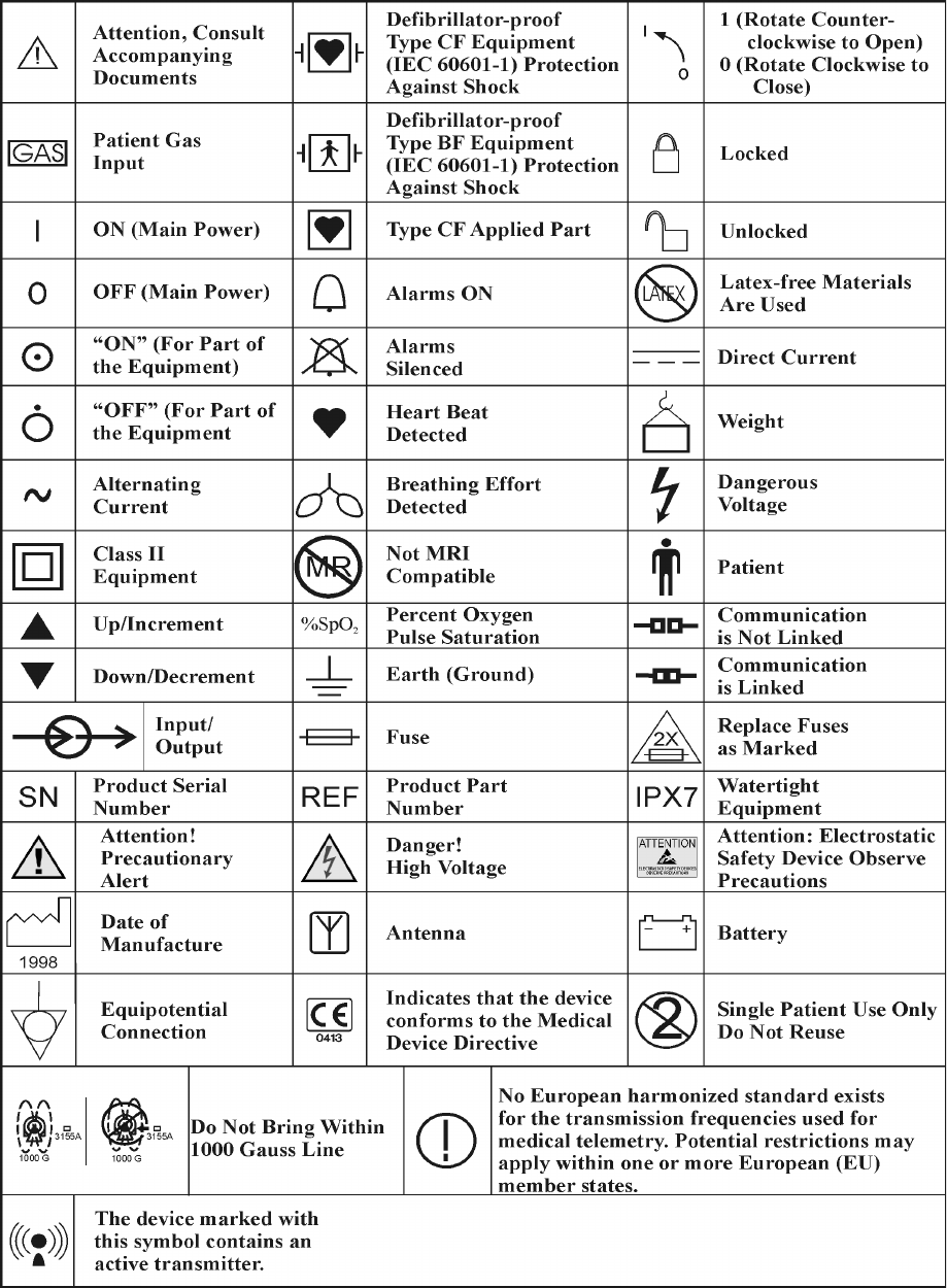
F-1
APPENDIX F
LIST OF SYMBOLS
NOTES