Invivo WBT1 WIRELESS BASIC TRIGGERING UNIT User Manual S User s Manual Wireless Modules
Invivo Corporation WIRELESS BASIC TRIGGERING UNIT S User s Manual Wireless Modules
UserManual.wiki
>
Invivo
>
WBT1 User Manual
Users Manual
Navigation menu
Upload a User Manual
Namespaces
Wiki Guide
HTML
PDF
Info
Views
User Manual
Discussion / Help
Navigation

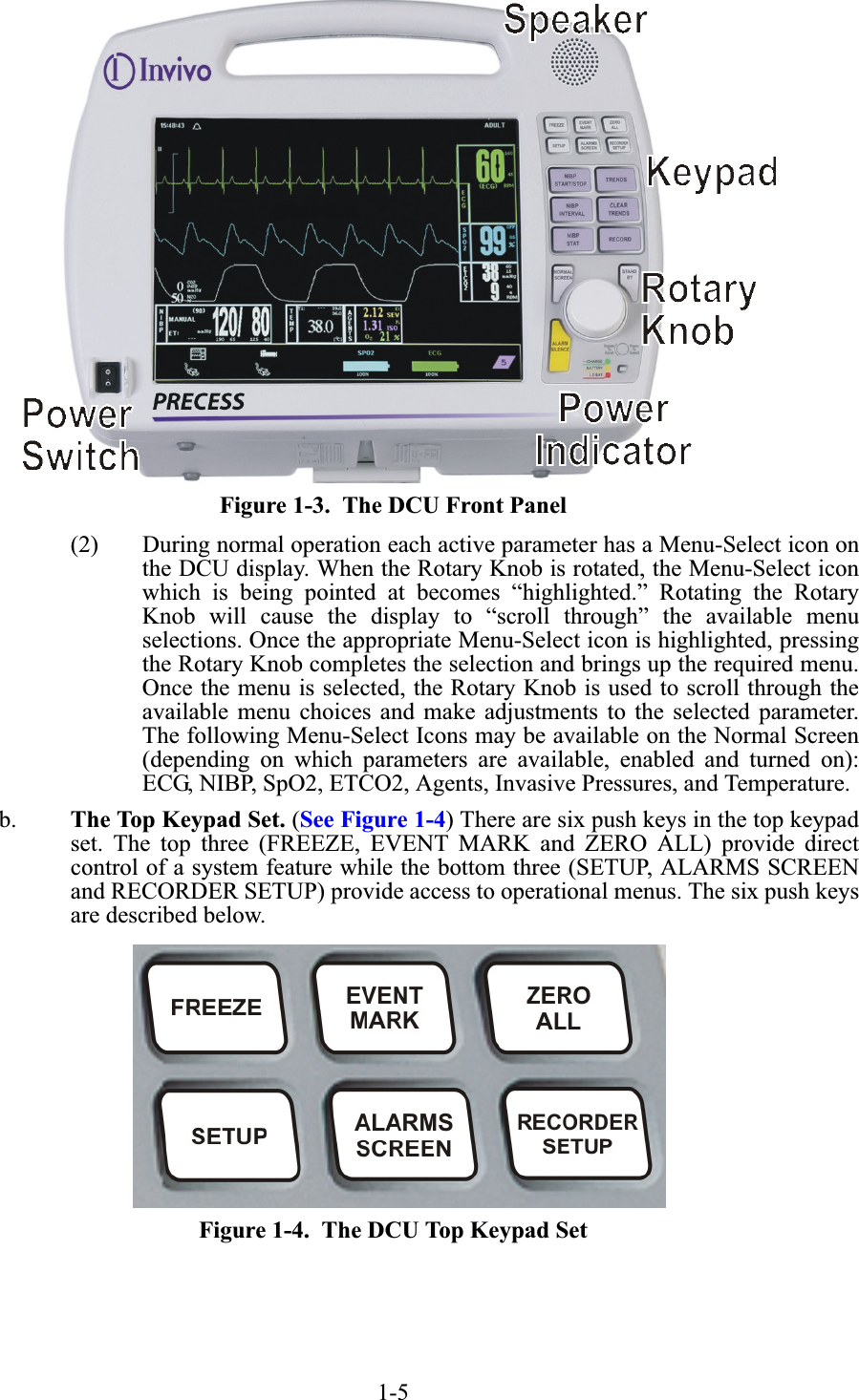
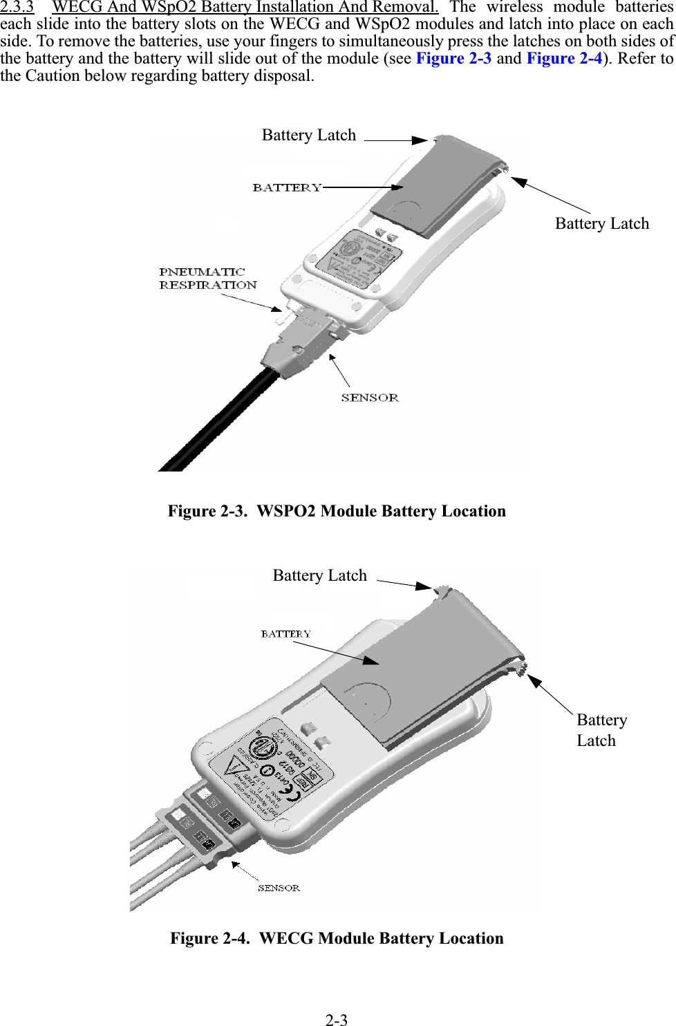
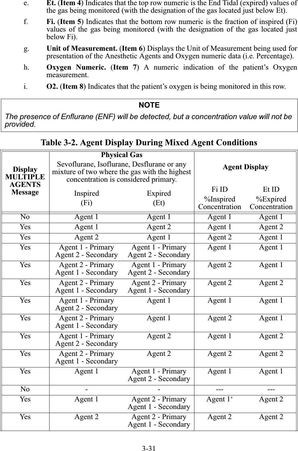
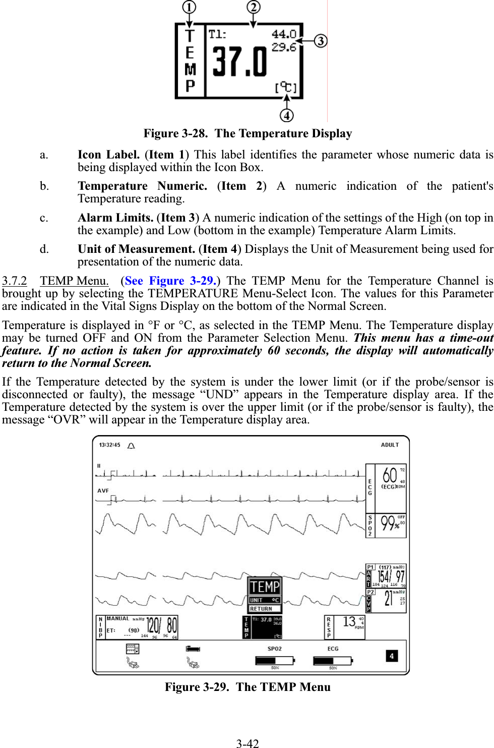
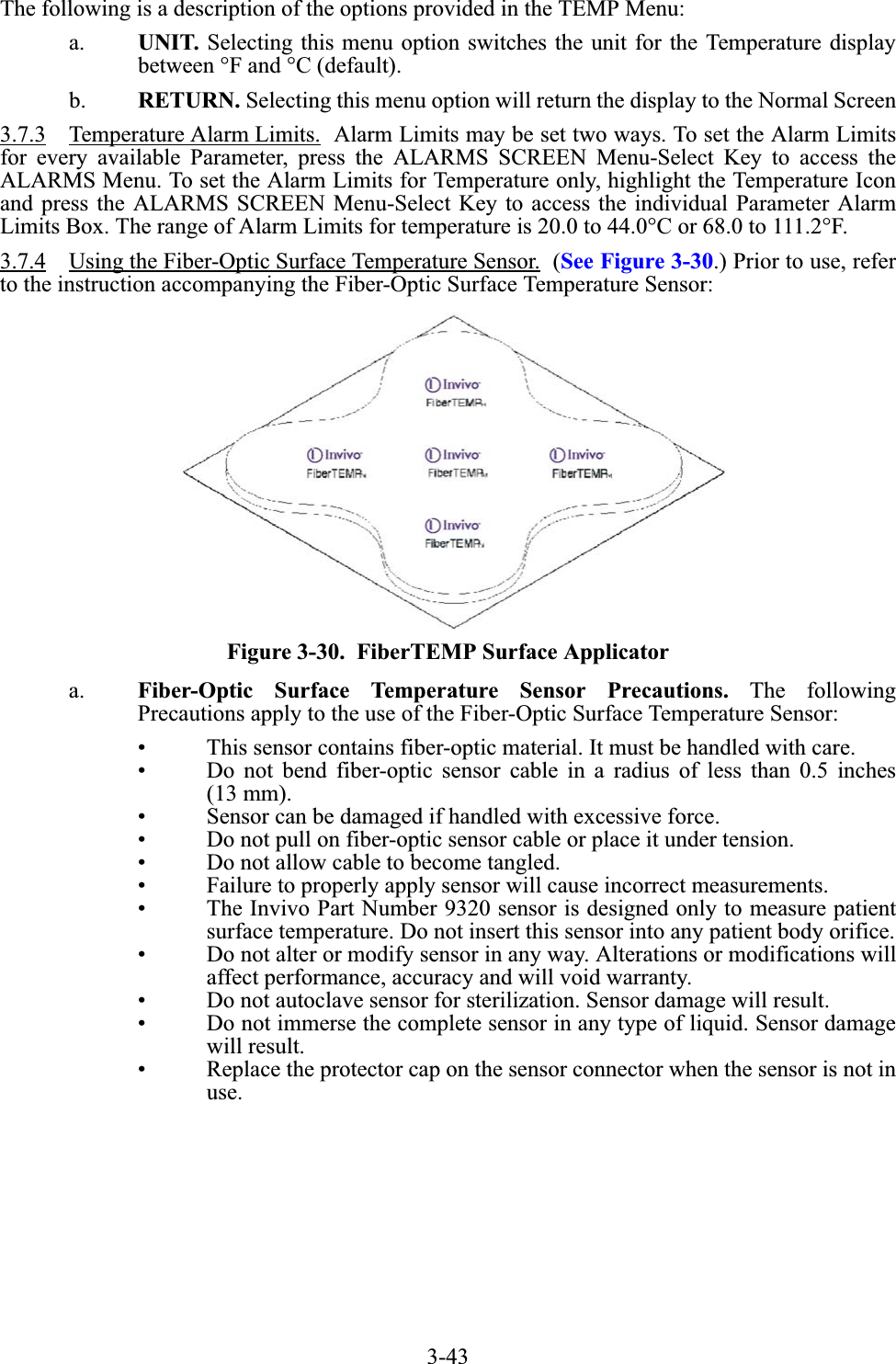
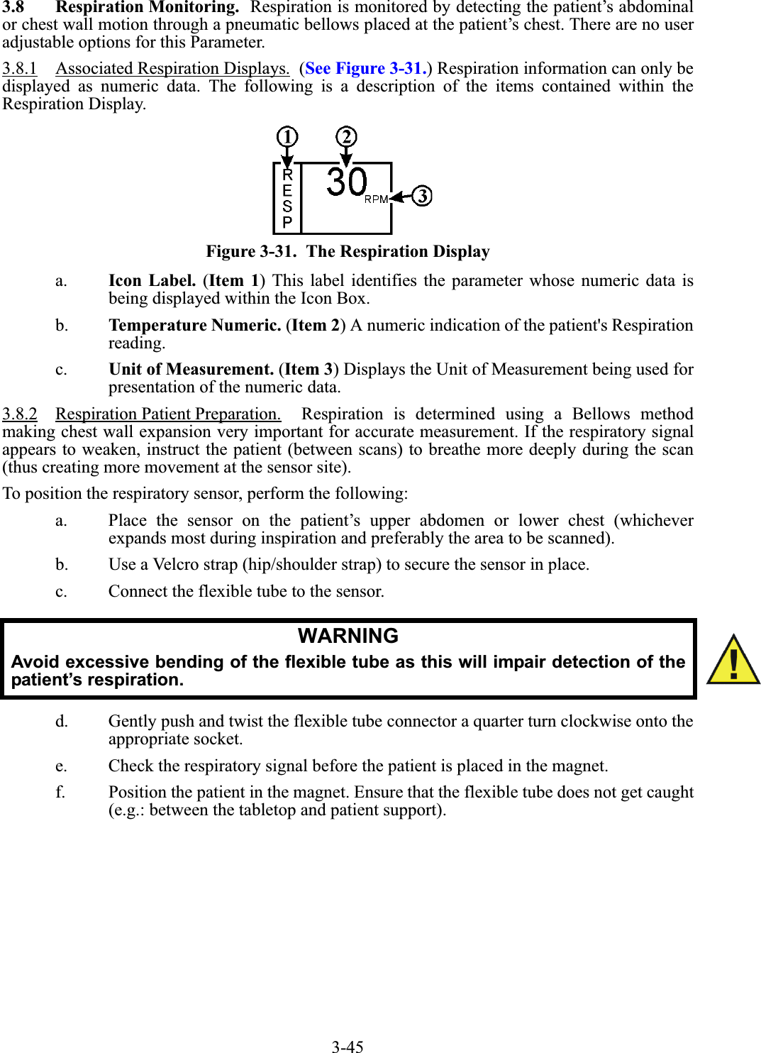
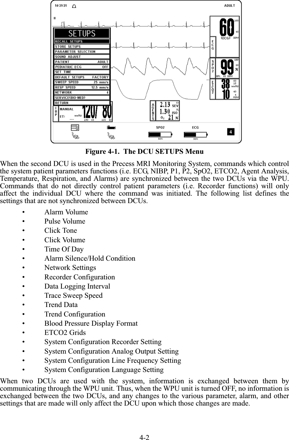
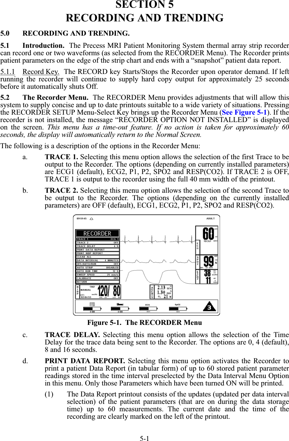
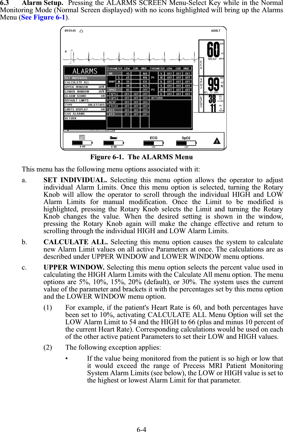
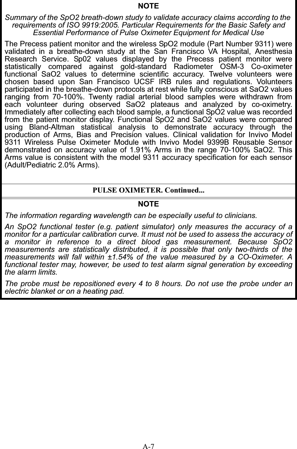
![ivPRECAUTIONSElectrical SafetyAlways disconnect the Precess MRI Patient Monitoring System from AC Main Power beforeperforming cleaning or maintenance system. To avoid an electrical hazard, never immerse anypart of the patient monitoring system in any cleaning agent fluid or attempt to clean it with liquidcleaning agents. If the Precess MRI Patient Monitoring System becomes accidentally wet during use, discontinueoperation until all affected components have been cleaned and permitted to dry completely.Contact Invivo Service Support if additional information is required.Shock hazard exists if operated without chassis cover. Refer servicing to Invivo Service Supportpersonnel only.For continued protection against fire hazard, replace fuses with same type and rating only.Connect the Precess MRI Patient Monitoring System to a three-wire, grounded, hospital-gradereceptacle only. The three-conductor plug must be inserted into a properly wired three-wirereceptacle.Do not under any circumstances remove the grounding conductor from the power plug.Avoid use of electrical power extension cords. Electrical power extension cords will create asafety hazard by compromising the grounding integrity of the Precess MRI Patient MonitoringSystem.None of the interconnection ports on the rear of the DCU or WPU (e.g. Communication Ports,Auxiliary Input/Output port [AUX I/O], USB port, Keyboard, Gating Connection or Video Input)are intended for direct patient connection. An electric shock hazard can exist if the patient iselectrically connected to any of these connections.The Precess MRI Patient Monitoring System and its listed accessories may be safely powered bythe voltages 100-240 VAC having a frequency of 50 or 60 Hz.If the integrity of the earth ground conductor of the AC main power cable is in doubt, operate thePrecess MRI Patient Monitoring System on internal battery power until proper earth groundconnection is confirmed.](https://usermanual.wiki/Invivo/WBT1/User-Guide-1090493-Page-10.png)
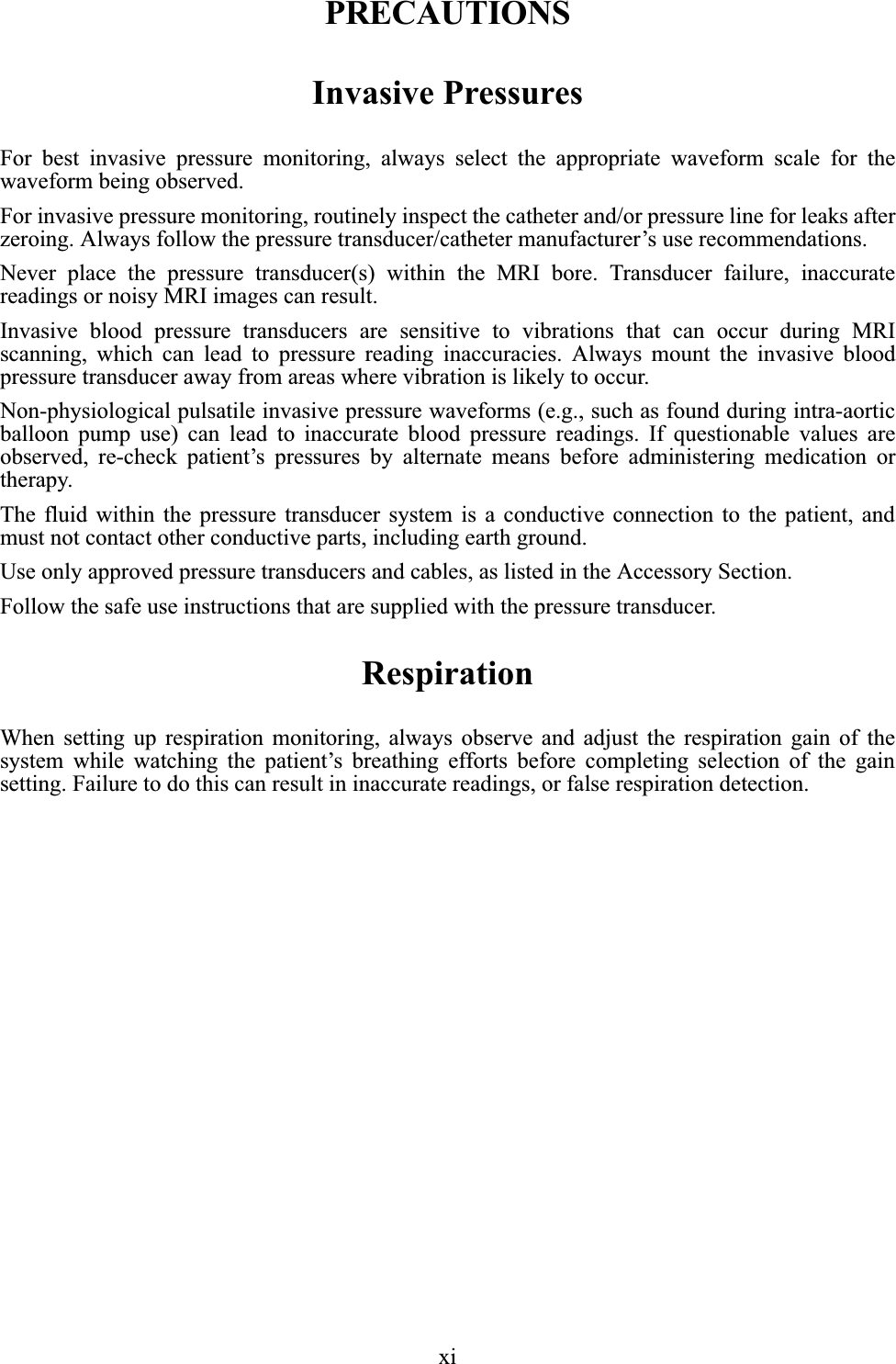

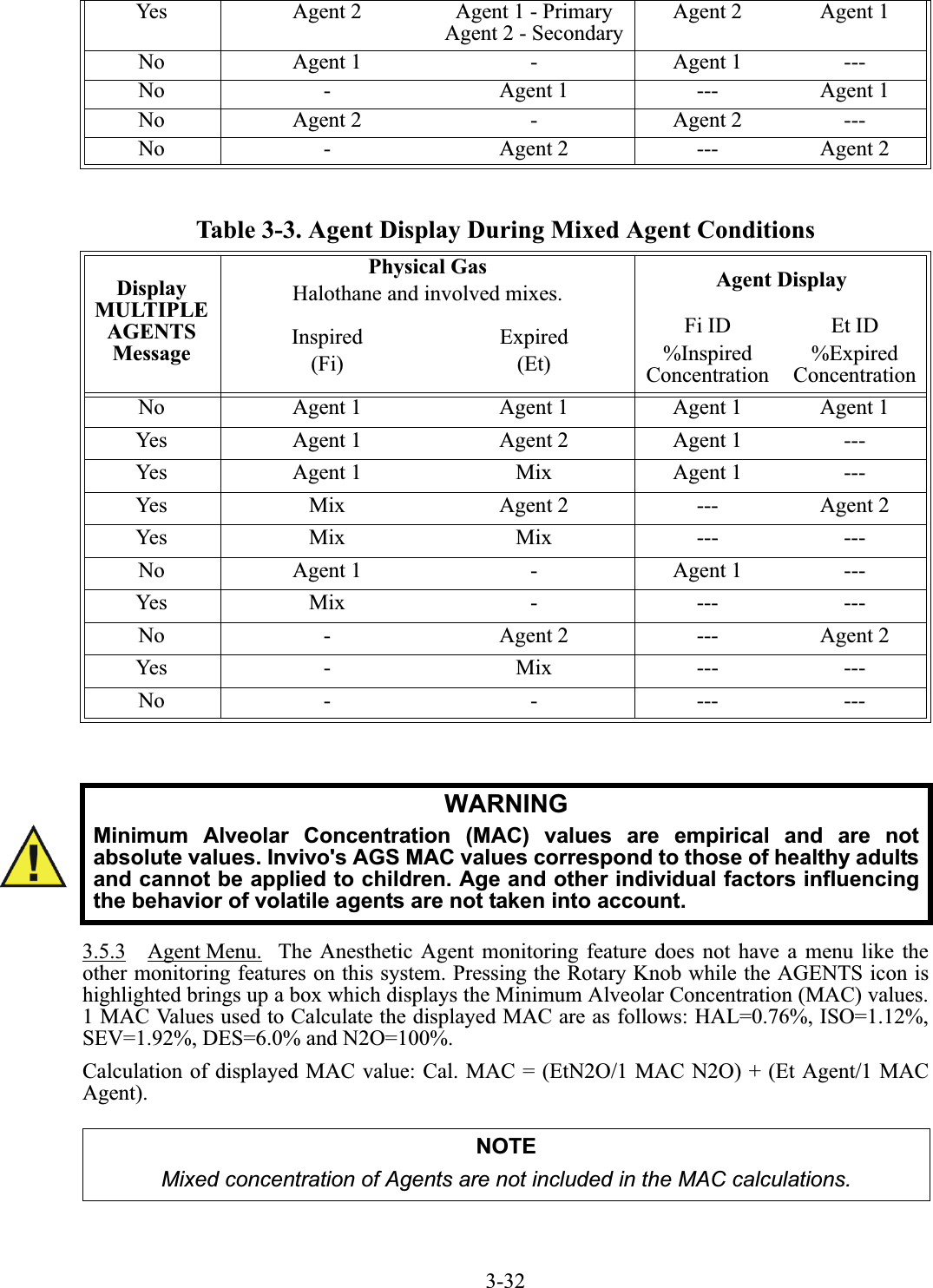
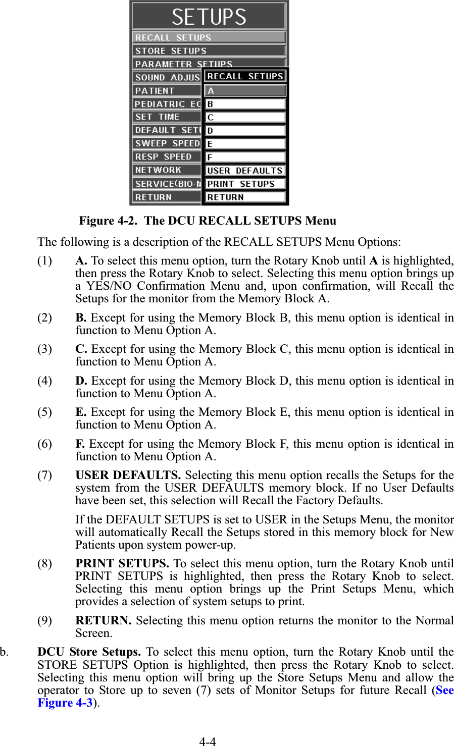
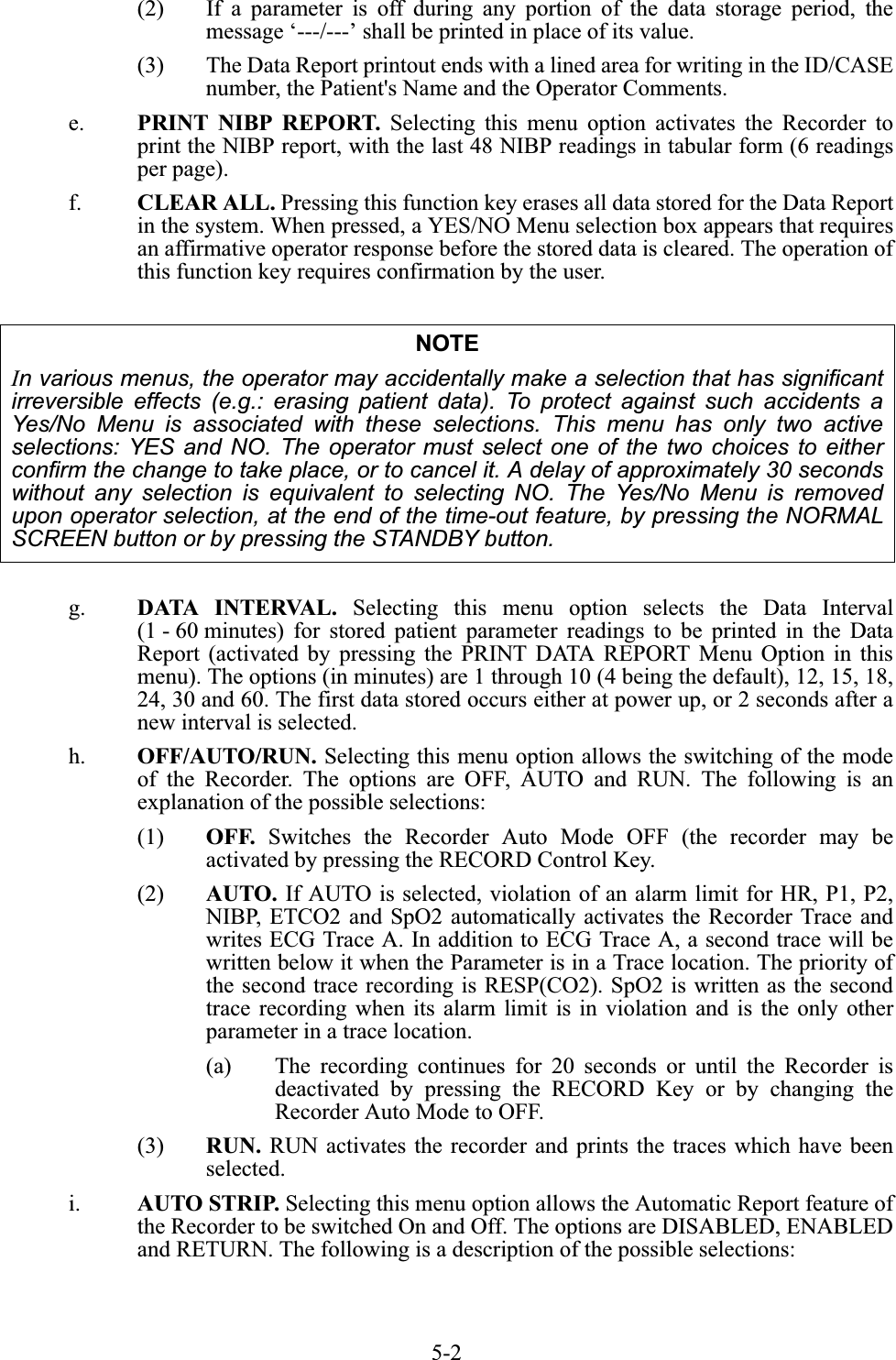

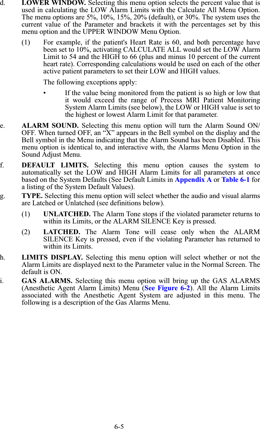
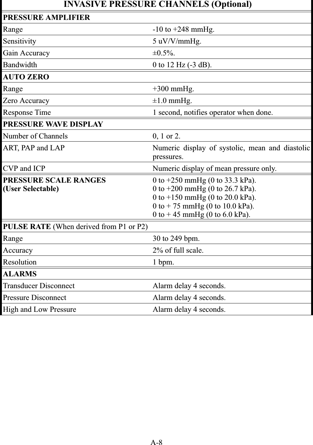
![A-10Low-Flow End-Tidal CO2 [Optional]Side stream, non-dispersive infrared absorption technique. Including multiple water trappedfiltration system and microprocessor logic control of sample handling and calibration.Output CO2 Waveform, ETCO2, FiCO2, Respiration Rate.Units of measurement mmHg or KPa.Measurement Range CO2: 0 to 76 mmHg.Accuracy CO2: ±4 mmHg or ±12%, whichever is greater.Resp: ±1 Respiration/minute (RPM) or ±3%, whichever is greater.Warm-up Time < 2 minutes.Zero Calibration Interval Automatic or user requested.Flow Rate 80 mL/minute ±16mL/minute.Respiration Rate(Rate permitting specified EtCO2 accuracy)Accuracy: 0 to 60 respirations/minute.Respiration Range 4 to 100 respirations/minute.Total System Response Time From 2.5% CO2 to 5% CO2 Avg. value of 14.313 seconds.From Ambient Air to 5% CO2 Avg. value of 14.193 seconds.Drift 0% Drift was observed during a 6 hour period.Sample Cell Volume < 50 micro liters.Operating Temperature 15 to 35°C (59 to 95°F)ALARM LIMITSETCO2 Alarm Limits Low: OFF or 5 to 60 mmHgHigh: 7 to 80 or OFF mmHgInspired CO2 25 mmHg (Fixed)Respiration Alarm Limits Low: OFF or 4 to 40 RPMHigh: 20 to 150 ROM or OFFMEASUREDGASINTERFERING GASES AND EFFECTSN20 HAL ENF ISO SEVO Xenon Helium DES Ethanol Isopropanol Acetone MethaneCarbon DioxideNE @ 60%NE @ 4%NE @ 5%NE @ 5%NE @ 5%ME @ 80%ME @ 50%NE @ 15%NE @ 5%NE @ 0.548%NE @ 2%NE @ 2%](https://usermanual.wiki/Invivo/WBT1/User-Guide-1090493-Page-141.png)