Invivo WBT1 WIRELESS BASIC TRIGGERING UNIT User Manual S User s Manual Wireless Modules
Invivo Corporation WIRELESS BASIC TRIGGERING UNIT S User s Manual Wireless Modules
Invivo >
Users Manual

Invivo Corporation
PRECESS MRI PATIENT MONITORING SYSTEM
OPERATIONS MANUAL

NOTE
Notified body number 0413 is only relevant for the MDD 93/42/EEC Directive.
TABLE OF CONTENTS
Paragraph Number Page Number
Equipment Classification................................................................................................................. i
Precautions...................................................................................................................................... ii
User Responsibility...................................................................................................................... xvi
User Responsibility Precess MRI Patient Monitoring Accessories............................................ xvii
Part Number Precess MRI Patient Monitoring Accessories...................................................... xviii
1.0 INTRODUCTION. ........................................................................................................ 1-1
1.1 Product Description ......................................................................................................... 1-1
1.1.1 System Parameters............................................................................................... 1-2
1.1.2 User Interface....................................................................................................... 1-3
1.1.3 Versatility............................................................................................................. 1-3
1.2 Wireless Processor Unit (WPU) ...................................................................................... 1-3
1.2.1 Operating Environment........................................................................................ 1-3
1.2.2 Power Supply....................................................................................................... 1-3
1.3 Patient Connections ......................................................................................................... 1-3
1.3.1 NIBP and Agent Monitoring................................................................................ 1-3
1.3.2 Invasive Pressure Monitoring .............................................................................. 1-3
1.3.3 Temperature Monitoring...................................................................................... 1-3
1.4 ECG Monitoring .............................................................................................................. 1-3
1.5 SpO2 Monitoring ............................................................................................................. 1-4
1.6 Display Control Unit (DCU)............................................................................................ 1-4
1.6.1 DCU Controls ...................................................................................................... 1-4
1.6.2 DCU Display...................................................................................................... 1-10
1.7 Cleaning. ........................................................................................................................ 1-18
1.7.1 Cleaning Accessories......................................................................................... 1-18
2.0 INSTALLATION........................................................................................................... 2-1
2.1 Unpacking The System.................................................................................................... 2-1
2.2 System Configuration. ..................................................................................................... 2-1
2.3 Battery Installation and Removal. ................................................................................... 2-1
2.3.1 Battery Locations................................................................................................. 2-1
2.3.2 WPU And DCU Battery Installation And Removal ............................................ 2-2
2.3.3 WECG And WSpO2 Battery Installation And Removal..................................... 2-3
2.4 Battery Charging.............................................................................................................. 2-5
2.4.1 WPU And DCU Battery Charging....................................................................... 2-5
2.4.2 WECG/WSpO2 Battery Charging ....................................................................... 2-5
2.5 Battery Operation........................................................................................................... 2-10
2.6 System Setup.................................................................................................................. 2-10
2.6.1 WPU and DCU .................................................................................................. 2-10
2.7 System Location ............................................................................................................ 2-13
2.8 Before Connecting To A Patient.................................................................................... 2-13
3.0 PATIENT PARAMETERS........................................................................................... 3-1
3.1 ECG Monitoring .............................................................................................................. 3-1
3.1.1 Wireless ECG Module and ECG Patient Lead Wires.......................................... 3-1
3.1.2 ECG Electrode - Use only Invivo Quadtrode MRI ECG Electrodes.................. 3-2
3.1.3 Associated Waveforms and Displays .................................................................. 3-4
3.1.4 The ECG Menu.................................................................................................... 3-4
3.1.5 ECG Alarm Limits............................................................................................... 3-8
3.1.6 ECG Trended Data............................................................................................... 3-8
3.1.7 ECG Messages..................................................................................................... 3-9
3.2 Non-Invasive Blood Pressure (NIBP) Monitoring .......................................................... 3-9
3.2.1 Theory of Oscillometric Measurement .............................................................. 3-11
3.2.2 NIBP Patient and Cuff Preparation.................................................................... 3-12
3.2.3 Associated NIBP Displays................................................................................. 3-12
3.2.4 The NIBP Menu................................................................................................. 3-14
3.2.5 NIBP Menu Options .......................................................................................... 3-14
3.2.6 Using the Automatic NIBP Interval Mode ........................................................ 3-17
3.2.7 Manually Starting/Stopping an NIBP Reading Cycle ....................................... 3-17
3.2.8 NIBP STAT Mode Operation ............................................................................ 3-17
3.2.9 NIBP Alarm Limits............................................................................................ 3-17
3.2.10 NIBP Adult vs. Neonatal Mode Operation........................................................ 3-17
3.2.11 NIBP Trended Data ........................................................................................... 3-18
3.2.12 NIBP Messages.................................................................................................. 3-18
3.3 SpO2 Monitoring ........................................................................................................... 3-19
3.3.1 Wireless SpO2 Module and Fiber-Optic SpO2 Sensor ..................................... 3-19
3.3.2 SpO2 Sensor Positioning ................................................................................... 3-19
3.3.3 Associated SpO2 Waveforms and Displays ...................................................... 3-20
3.3.4 SpO2 Menu ........................................................................................................ 3-20
3.3.5 SpO2 Alarm Limits............................................................................................ 3-21
3.3.6 SpO2 Trended Data ........................................................................................... 3-22
3.3.7 SpO2 Messages.................................................................................................. 3-22
3.4 End-tidal CO2 (ETCO2) Monitoring............................................................................. 3-23
3.4.1 Water Trap and Sampling Line Preparation ...................................................... 3-23
3.4.2 Water Trap Replacement ................................................................................... 3-25
3.4.3 Associated ETCO2 Waveforms and Displays ................................................... 3-25
3.4.4 ETCO2 Menu..................................................................................................... 3-26
3.4.5 Calibration of CO2 Measurement System ......................................................... 3-27
3.4.6 ETCO2 Alarm Limits ........................................................................................ 3-29
3.4.7 ETCO2 Trended Data ........................................................................................ 3-29
3.4.8 ETCO2 Messages .............................................................................................. 3-29
3.5 Anesthetic Agent/Oxygen Monitoring........................................................................... 3-29
3.5.1 Anesthetic Agent Patient and Tubing Preparation............................................. 3-30
3.5.2 Associated Anesthetic Agent Displays .............................................................. 3-30
3.5.3 Agent Menu ....................................................................................................... 3-32
3.5.4 Gas Calibration .................................................................................................. 3-33
3.5.5 Agent Alarm Limits ........................................................................................... 3-34
3.5.6 Agent Trended Data........................................................................................... 3-34
3.5.7 Agent/O2 Messages ........................................................................................... 3-34
3.5.8 Oxygen Monitoring............................................................................................ 3-35
3.6 Invasive Pressure Monitoring ........................................................................................ 3-36
3.6.1 Invasive Pressure Transducer Preparation......................................................... 3-36
3.6.2 Associated Invasive Pressure Waveforms and Displays ................................... 3-37
3.6.3 The Invasive Pressure Menu.............................................................................. 3-38
3.6.4 Invasive Pressure Alarm Limits......................................................................... 3-40
3.6.5 Invasive Pressure Trended Data ........................................................................ 3-41
3.6.6 Invasive Pressure Messages............................................................................... 3-41
3.7 Temperature Monitoring................................................................................................ 3-41
3.7.1 Associated Temperature Displays ..................................................................... 3-41
3.7.2 TEMP Menu ...................................................................................................... 3-42
3.7.3 Temperature Alarm Limits ................................................................................ 3-43
3.7.4 Using the Fiber-Optic Surface Temperature Sensor.......................................... 3-43
3.7.5 Temperature Trended Data ................................................................................ 3-44
3.7.6 Temperature Messages ...................................................................................... 3-44
3.8 Respiration Monitoring.................................................................................................. 3-45
3.8.1 Associated Respiration Displays ....................................................................... 3-45
3.8.2 Respiration Patient Preparation ......................................................................... 3-45
4.0 PREPARATION FOR USE.......................................................................................... 4-1
4.1 Introduction...................................................................................................................... 4-1
4.2 Setups Menu .................................................................................................................... 4-1
4.2.1 DCU Setups Menu. .............................................................................................. 4-1
4.2.2 Store/Recall Setups .............................................................................................. 4-3
4.3 Monitor Initialization..................................................................................................... 4-16
4.3.1 Default Initialization .......................................................................................... 4-16
4.3.2 Pre-Configured Initialization ............................................................................. 4-16
5.0 RECORDING AND TRENDING. ............................................................................... 5-1
5.1 Introduction...................................................................................................................... 5-1
5.1.1 Record Key .......................................................................................................... 5-1
5.2 The Recorder Menu ......................................................................................................... 5-1
5.3 Recording Charts ............................................................................................................. 5-3
5.3.1 Strip Chart Record ............................................................................................... 5-3
5.3.2 Tabular Chart Record........................................................................................... 5-4
5.3.3 Trend Chart .......................................................................................................... 5-4
5.3.4 System Data Report ............................................................................................. 5-5
5.4 Loading Recorder Paper .................................................................................................. 5-5
5.5 Trending Feature.............................................................................................................. 5-5
5.5.1 History Menu Options ......................................................................................... 5-5
6.0 ALARMS. ....................................................................................................................... 6-1
6.1 Introduction...................................................................................................................... 6-1
6.2 Alarm Limits.................................................................................................................... 6-1
6.2.1 Default (Pre-Set) Alarm Limits ........................................................................... 6-1
6.2.2 Range of High and Low Alarm Limits ................................................................ 6-3
6.3 Alarm Setup ..................................................................................................................... 6-4
6.3.1 Parameter Alarms Status Screen.......................................................................... 6-7
6.4 Turning Alarms OFF on Individual Parameters .............................................................. 6-7
6.5 Alarm Violations.............................................................................................................. 6-7
6.6 Adjusting the Alarm Tone Volume ................................................................................. 6-8
6.6.1 Disabling the Alarm Tone.................................................................................... 6-8
6.7 Standby Mode .................................................................................................................. 6-9
specifications .............................................................................................................................. A-1
repair ............................................................................................................................................B-1
warranty .......................................................................................................................................C-1
Declaration of conformity........................................................................................................... D-1
List of symbols.............................................................................................................................E-1
EMC............................................................................................................................................. F-1
NOTES........................................................................................................................................ G-1

i
EQUIPMENT CLASSIFICATION
Classification according to IEC-60601-1
According to the type of protection against
electrical shock:
Class I equipment.
According to the degree of protection against
electrical shock:
Type CF (defibrillator-proof) equipment.
According to the degree of protection against
harmful ingress of water:
Ordinary equipment (enclosed equipment
without protection against ingress of water).
According to the methods of sterilization or
disinfection:
Non-sterilizable. Use of liquid surface
disinfectants only.
According to the mode of operation: Continuous operation.
Equipment not suitable for use in the presence of flammable anesthetic mixture with air or with
oxygen or nitrous oxide.
ii
PRECAUTIONS
General
Laws in the USA, Canada and E.U. restricts this device to sale by, or on, the order of a physician.
The Precess MRI Patient Monitoring System should not be used to transport a patient outside of a
healthcare facility.
The position of the patient and the patient’s physiological condition may affect the accuracy of the
measurements. Always consult a physician for interpretation of measurements made by the
Precess MRI Patient Monitoring System.
Secure all components on mounting solutions recommended in the Accessory Listing section.
Failure to secure all components could result in damage to the Precess MRI Patient Monitoring
System.
Do not use the Precess MRI Patient Monitoring System in the presence of flammable anesthetics.
Using the Precess MRI Patient Monitoring System in the presence of flammable anesthetics
would create an explosion hazard.
The operator must read and thoroughly understand this operations manual before attempting to
use the Precess MRI Patient Monitoring System.
Perform operational checkout before each use. If the Precess MRI Patient Monitoring System
fails to fuction accurately, remove it from use, and refer it to Invivo service personnel.
When an “X” appears in the Alarm Bell symbol, the audible alarm tone will not sound for any
reason.
Use only recommended Invivo patient cable, lead wires, cuffs, hoses, sensors, tubing, etc. Using
other brands will compromise the safety and accuracy of the Precess MRI Patient Monitoring
System. A list of all Invivo brand accessories can be found in the Accessories section within this
manual.
For continued operation, always connect the Precess MRI Patient Monitoring System to AC Main
Power when a Low Battery indication signal occurs. Failure to do this can lead to the interruption
of monitoring and/or damage to the batteries.
The Precess MRI Patient Monitoring System must be used and stored according to the following
environmental specifications:
Operating Temperature:10 to 40°C (50 to 104°F), or 15 to 35°C (59 to 95°F) when EtCO2
or anesthetic agents parameters are operating.
Storage Temperature: Batteries (Invivo Part Numbers 9093 or 9064, and 9065):
0 to 40°C (32 to 104°F).
Disposable Oxygen (O2) Cell (Invivo Part Number 9445):
-40 to 45°C (-40 to 113°F).
WPU, DCU, wireless modules, and additional accessories:
-40 to +70°C (0 to 158°F). When storing the 3160 system in
temperatures beyond the minimum ranges mentioned above,
remove the designated component and store it appropriately.
Relative Humidity: 0 to 80%, non-condensing
Failure to follow these specifications may affect the accuracry of the Precess MRI Patient
Monitoring System.
Do not apply unnecessary pressure to the screen area of the Display Control Unit (DCU). Severe
pressure applied to the screen area of the DCU could result in damage or failure of this screen.
iii
All equipment not complying with IEC 60601-1 must be placed outside the patient environment.
Only connect IEC 60601-1-compliant equipment to the Precess MRI Patient Monitoring System.
Always check the summation of leakage currents when several items of equipment are
interconnected.
Annual preventative maintenance is recommended unless stated otherwise in the service manual.
For proper equipment maintenance, perform the service procedures at the recommended intervals
as described in the service manual, Part Number 9568.
Single-use devices should be disposed of after use and must never be reused.
Organic vapors (e.g. from cleaning agents) in sampling line or room air may alter anesthetic agent
readings.
Alcohol in patient's breath may modify the anesthetic agent readings.
Always consult a physician for interpretation of waveforms and values.
All system alarms are categorized as high priority, unless otherwise specified.
Warning Statement
The manufactuer is not responsible for any radio or TV interference caused by unauthorized modifications
to this equipment. Such modification could void the user's authority to operate the equipment.

iv
PRECAUTIONS
Electrical Safety
Always disconnect the Precess MRI Patient Monitoring System from AC Main Power before
performing cleaning or maintenance system. To avoid an electrical hazard, never immerse any
part of the patient monitoring system in any cleaning agent fluid or attempt to clean it with liquid
cleaning agents.
If the Precess MRI Patient Monitoring System becomes accidentally wet during use, discontinue
operation until all affected components have been cleaned and permitted to dry completely.
Contact Invivo Service Support if additional information is required.
Shock hazard exists if operated without chassis cover. Refer servicing to Invivo Service Support
personnel only.
For continued protection against fire hazard, replace fuses with same type and rating only.
Connect the Precess MRI Patient Monitoring System to a three-wire, grounded, hospital-grade
receptacle only. The three-conductor plug must be inserted into a properly wired three-wire
receptacle.
Do not under any circumstances remove the grounding conductor from the power plug.
Avoid use of electrical power extension cords. Electrical power extension cords will create a
safety hazard by compromising the grounding integrity of the Precess MRI Patient Monitoring
System.
None of the interconnection ports on the rear of the DCU or WPU (e.g. Communication Ports,
Auxiliary Input/Output port [AUX I/O], USB port, Keyboard, Gating Connection or Video Input)
are intended for direct patient connection. An electric shock hazard can exist if the patient is
electrically connected to any of these connections.
The Precess MRI Patient Monitoring System and its listed accessories may be safely powered by
the voltages 100-240 VAC having a frequency of 50 or 60 Hz.
If the integrity of the earth ground conductor of the AC main power cable is in doubt, operate the
Precess MRI Patient Monitoring System on internal battery power until proper earth ground
connection is confirmed.
v
PRECAUTIONS
Patient Safety
Whenever a patient is under anesthesia or connected to a ventilator constant attention by
qualified medical personnel is needed. Some equipment malfunctions may occur in spite of
equipment or monitoring alarms.
Always test the sampling line adapter for a tight connection and proper operation before attaching
to a patient.
As with all medical equipment, carefully route patient cabling to reduce the possibility of patient
entanglement or strangulation.
Occupational Safety
Connect the sample gas outlet on the monitor's rear panel to a scavenging system to prevent
pollution of room air.
Handle the Patient Sampling Line and its contents as you would any body fluid. Infectious hazard
may be present.

vi
PRECAUTIONS
MRI Use Precautions
Certain components of the Precess MRI Patient Monitoring System will be affected by the
magnetic and radio frequency fields present in your MRI magnet room. Confer with your MRI
physicist and/or Radiology staff to identify the proper placement and use areas for the Precess
MRI Patient Monitoring System and its accessories, as defined on the system or accessory
labeling. Failure to properly place the Precess MRI Patient Monitoring System and its accessories
in the magnet room will result in system or accessory failure, and possible patient or user injury.
Possible damage to the NIBP or ETCO2 pump could occur. A dB/dT above 40T/second may
saturate the ECG amplifier of this device, leading to erratic readings. Always verify proper
communication of the Precess MRI Patient Monitoring System with the corresponding Remote
Monitor (Display Control Unit (DCU)) prior to patient use.
MRI Magnet Room Placement
The Precess MRI Patient Monitoring System is designed to be used in conjunction with a Remote
Monitor (Display Control Unit (DCU)).
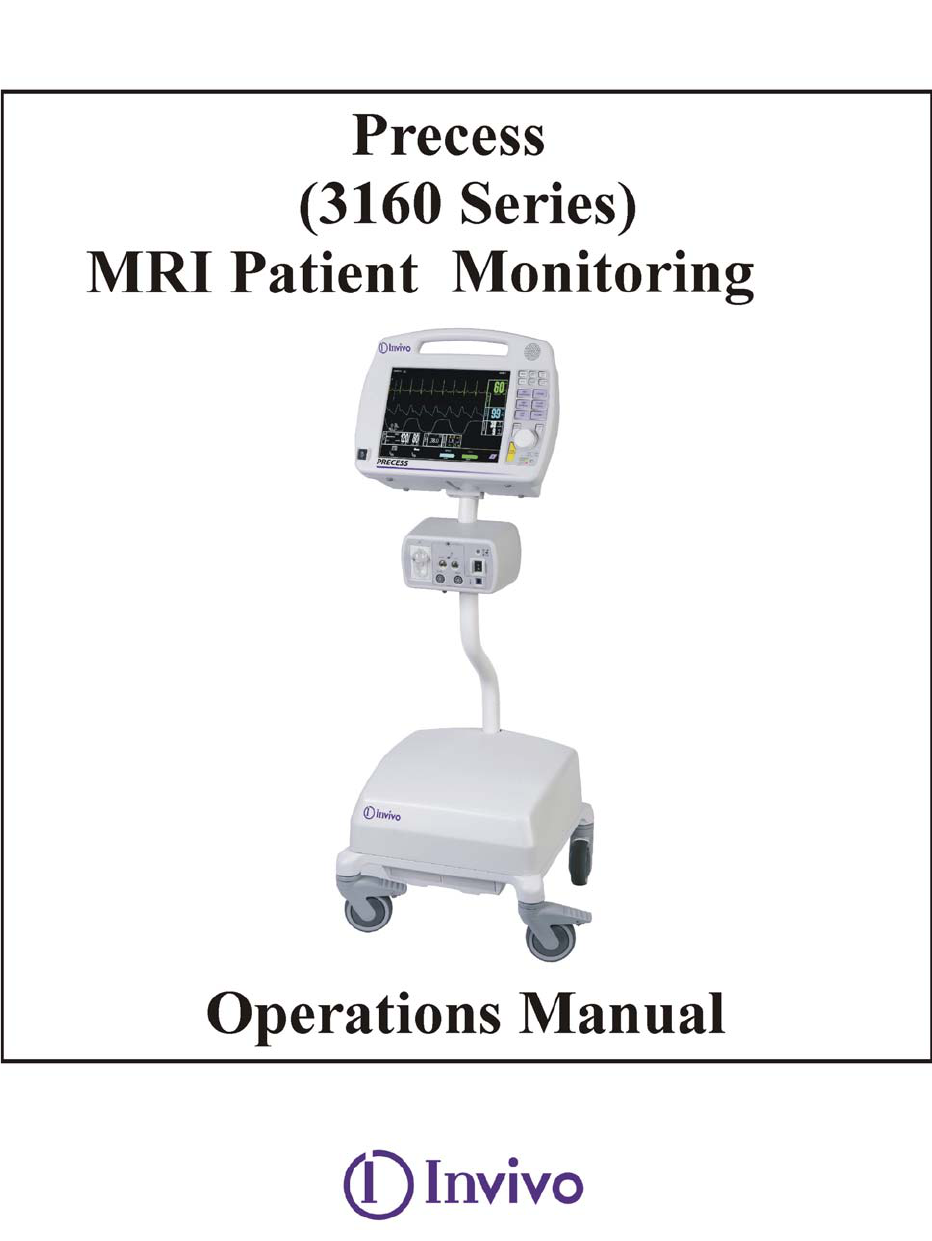
The Precess MRI Patient Monitoring System is specially designed not to interfere with MRI
operations. IT MAY BE USED INSIDE THE MRI MAGNET ROOM IN A
LOCATION AT OR OUTSIDE THE 5,000 (5,000 OR LESS) GAUSS (0.5T)
FIELD LINE OF THE MRI SYSTEM, AS MEASURED FROM THE
CENTER LINE OF THE MRI BORE, BUT IN NO CASE CLOSER THAN
3 FEET (1 METER) FROM THE MRI SYSTEM. ALWAYS ENSURE THAT
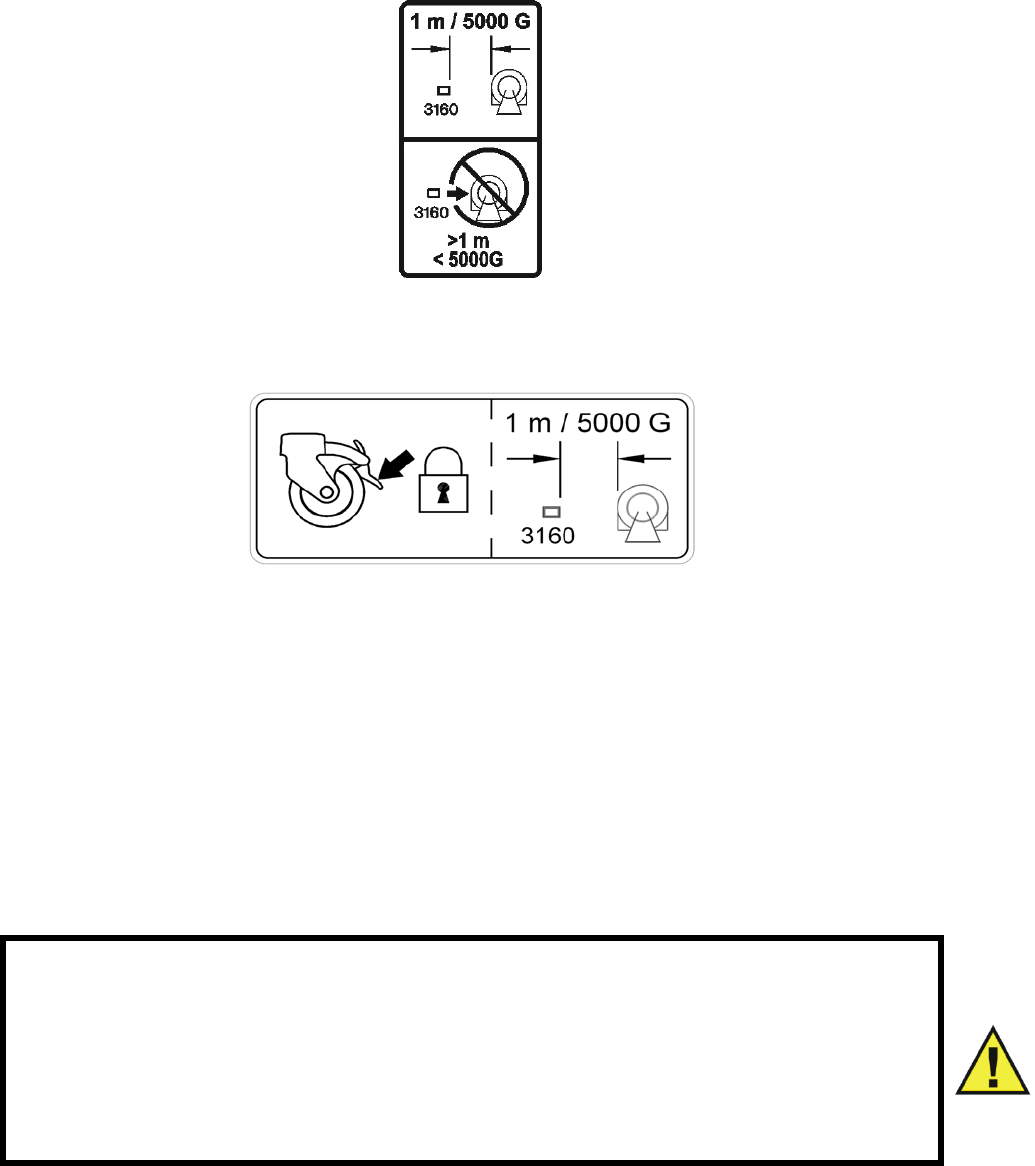
THE WHEELS ARE IN THE LOCKED POSITION WHEN THE
MONITORING SYSTEM IS LEFT UNATTENDED.
Field strength variations in a particular MRI magnet room (which may be due to active shielding
technology, manufacturer variability, future enhancements, etc) can make distinguishing the 5,000
Gauss level difficult and therefore the Precess MRI Patient Monitoring System must never be
placed closer than 3 feet (1 meter) from the MRI System. This variation may require moving the
Precess MRI Patient Monitoring System away from the magnet if system abnormalities or
malfunctions are observed. Prior to clinical use, the operator must be aware of the minimum
distance from the MRI System for proper operation.
If brought closer than 3 feet (1 meter) and/or the 5,000 Gauss Field Line, system failure and/or
patient or user injury may result.
vii
5,000 G/3 FT (1M), WHICHEVER IS FARTHER FROM THE MRI SYSTEM
ALWAYS ENSURE THAT THE WHEELS ARE IN THE LOCKED
POSITION WHEN THE MONITORING SYSTEM IS LEFT
UNATTENDED.
The Remote Monitor (Display Control Unit (DCU)) is also specifically designed not to interfere
with MRI operations. If the recorder option is present, it may be used in the magnet room at or
outside the 1,000 Gauss (0.1T) Field Line of the MRI System. Do not move the Remote Monitor
closer than the specified Gauss Field Line or damage (failure to operate) to the recorder may
result. If the recorder option is not present, the Remote Monitor may be used at or outside the
5,000 Gauss (0.5T) Field Line or no closer than 3 feet (1 meter) from the MRI System.
Dislodge the Precess MRI Patient Monitoring System by gently pulling from the base of the
system pole at its lowest point. This will prevent the base of the unit from experiencing higher
MRI pull forces in the vertical direction.
WARNING
If the Precess MRI Patient Monitoring System rolls to the face of the MRI
system due to magnetically induced pull force, DO NOT ATTEMPT TO
DISLODGE THE PRECESS MRI PATIENT MONITORING SYSTEM BY
PULLING FROM THE DOCKED REMOTE MONITOR OR GUIDE
HANDLE AT THE TOP OF THE PRECESS MRI PATIENT MONITORING
SYSTEM.

viii
PRECAUTIONS
Risk of RF current burn
Cables which become inadvertently looped during MRI act as conductive lines for RF induced
currents. When lead wires or other cables form a conductive loop in contact with the patient's
tissue, minor to severe burning can result.
Perform the following to minimize risk of RF current burn:
a. Place cables and lead wires neatly in straight alignment with no looping.
b. Use only the ECG Lead Wires designated for use with this product. See Accessory
List.
c. RF burn risk increases when multiple sensors/cables are in use. Such combinations
are not recommended.
d. The high radio frequency (RF) power used in MRI scanning poses an ever-present
risk of excessive heat at the monitoring sites and, therefore, the risk of RF current
burn. Power levels greater than S.A.R. of 4 w/kg increase the risk of patient
burns. As a result, monitoring of ECG at power levels of greater than 4 w/kg is not
recommended for the general patient population. Such monitoring must only be
attempted on conscious patients with good temperature reflex so they may warn
the operator of excessive heat at the monitoring sites.
e. High RF Power may cause patient heating or burns. Use caution for scan times
greater than 15 minutes. It is recommended that ECG electrode temperature be
checked during scans greater than 15 minutes.
MRI Compatibility
The Quadtrode MRI ECG Electrodes (Invivo Part Numbers 9303, 9371 and 9372), and ECG
Patient Lead Wires (Invivo Part Numbers 9224, 9223 and 9222), are compatible with Magnetic
Resonance Imaging (MRI) Systems within the following guidelines:
• MRI systems with static magnetic field strengths up to 3.0 Tesla.
• Usable within the MRI system bore with Specific Absorption Ratios (S.A.R.'s) up to
4.0 w/kg. Use with higher S.A.R.'s greatly increases the risk of patient burns. If scanned
directly across the plane of the ECG electrode element, a slight image distortion may be seen
at the skin surface where the electrode element is positioned.
ix
PRECAUTIONS
ECG
An inoperative ECG parameter or WECG module is indicated by absence of an ECG waveform
and a simultaneous Lead Fail alarm.
For best ECG, heart rate, and/or respiration monitoring, always select the optimal lead
configuration which has the least artifact and largest waveform(s) being detected for monitoring
use.
Failure to respond to a Lead Fail alarm will cause a lapse in your patient’s monitoring. Always
respond promptly to this and any other alarms.
Heart rate values may be adversely affected by cardiac arrhythmia, or by operation of electrical
stimulators.
NIBP
Always use recommended NIBP cuffs and hoses. Avoid compression or restriction of NIBP cuff
hose.
When using the NIBP portion of this instrument to measure blood pressure, remember that the
patient’s blood pressure readings are not continuous, but are updated each time a blood pressure
measurement is taken. Set a shorter interval for more frequent updating of the patient’s blood
pressure.
Do not attach the cuff to a limb being used for infusion. Cuff inflation can block infusion, possibly
causing harm to the patient.
Arrhythmias and/or erratic heart beats (or severe motion artifact, such as tremors or convulsions)
can result in inaccurate readings and/or prolonged measurements. If questionable readings are
obtained, re-check patient’s vital signs by alternate means before administering medication.
To ensure accurate and reliable measurements, use only recommended patient cuffs/hoses. Use
the appropriate cuff size for each patient as recommended by the current American Heart
Association (AHA) guidelines for blood pressure monitoring to ensure patient safety and
accuracy.
Routinely inspect the cuff and hose assemblies for proper attachment and orientation. Replace
cuff and/or hose assemblies with cracks, holes, tears, cuts, etc. that could cause leaks in the
system. If cuff and/or hose assemblies with damage which could result in leaks are used,
prolonged and/or inaccurate patient readings could result.
Use only cuffs designated by Invivo. See Accessory List on page xv.
This equipment complies in full to EN 1060-1:1996 + A1:2002, Specification for non-invasive
sphygmomanometers - Part 1: General requirements.
x
PRECAUTIONS
SpO2
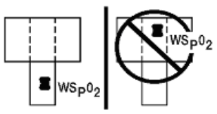
Avoid placement of the SpO2 sensor on the same limb with an inflated blood pressure cuff. Cuff
inflation could result in inaccurate readings and false alarm violations.
SpO2 monitoring requires the detection of valid pulses to correctly determine SpO2 and Heart
Rate values. During conditions of gross artifact, or in the absence of valid pulses, the SpO2/rate
values will not be correct.
The SpO2 patient monitoring portion of this system is intended to measure arterial hemoglobin
oxygen saturation of functional hemoglobin (saturation of hemoglobin functionally available for
transporting oxygen in the arteries). Significant levels of dysfunctional hemoglobins, such as
carboxyhemoglobin or methemoglobin, will affect the accuracy of the measurement. Also,
Cardiogreen and other intravascular dyes may, depending on their concentration, cause
inaccuracy of the SpO2 measurement.
Always shield the SpO2 sensor from extraneous incident light sources. Such extraneous light can
cause SpO2 reading or pulse detection errors.
Frequently inspect the SpO2 sensor site for possible pressure tissue necrosis during prolonged
monitoring. Reposition the sensor at least every four (4) hours. Special care must be exercised
when tape is used to secure the sensor, as the stretch memory properties of most tapes can easily
apply unintended pressure to the sensor site.
The numeric measurement values are updated every one (1) second on the system display.
A pulse oximeter should be considered an early warning device. As a trend towards patient
deoxygenation is indicated, blood samples must be analyzed by a laboratory co-oximeter to
completely understand the patient’s condition.
The pulse oximeter feature in this system is designed to display functional SpO2 values.
The pulse oximeter pulsatile waveform is not proportional to the pulse volume, but adjusts the
waveform amplitude as needed for proper viewing.
Arrhythmias and/or erratic heart beats (or severe motion artifact, such as tremors or convulsions)
can result in inaccurate readings and/or prolonged measurements. If questionable readings are
obtained, re-check patient’s vital signs by alternate means before administering medication.
Ambient light (including photodynamic therapy), physical movement (patient and imposed
motion), diagnostic testing, low perfusion, electromagnetic interference, electrosurgical units,
dysfunctional hemoglobin, presence of certain dyes and inappropriate positioning of the pulse
oximeter probe can all lead to inaccuracies of the pulse oximeter equipment.
xi
PRECAUTIONS
Invasive Pressures
For best invasive pressure monitoring, always select the appropriate waveform scale for the
waveform being observed.
For invasive pressure monitoring, routinely inspect the catheter and/or pressure line for leaks after
zeroing. Always follow the pressure transducer/catheter manufacturer’s use recommendations.
Never place the pressure transducer(s) within the MRI bore. Transducer failure, inaccurate
readings or noisy MRI images can result.
Invasive blood pressure transducers are sensitive to vibrations that can occur during MRI
scanning, which can lead to pressure reading inaccuracies. Always mount the invasive blood
pressure transducer away from areas where vibration is likely to occur.
Non-physiological pulsatile invasive pressure waveforms (e.g., such as found during intra-aortic
balloon pump use) can lead to inaccurate blood pressure readings. If questionable values are
observed, re-check patient’s pressures by alternate means before administering medication or
therapy.
The fluid within the pressure transducer system is a conductive connection to the patient, and
must not contact other conductive parts, including earth ground.
Use only approved pressure transducers and cables, as listed in the Accessory Section.
Follow the safe use instructions that are supplied with the pressure transducer.
Respiration
When setting up respiration monitoring, always observe and adjust the respiration gain of the
system while watching the patient’s breathing efforts before completing selection of the gain
setting. Failure to do this can result in inaccurate readings, or false respiration detection.
xii
PRECAUTIONS
End-tidal CO2 (ETCO2)
Verify that the patient’s breathing efforts and timing coincide with the DCU waveform before
completion of the patient set-up.
The ETCO2/N2O measurement displays the sampled value within 1 second of when the gas was
sampled.
Frequently inspect the ETCO2 patient tubing. Avoid kinking of the ETCO2 patient tubing that can
result in leaking, reduction, or cut-off of the sample gas flow. Inaccurate gas measurements could
result.
ETCO2 patient tubing and its associated components are intended for single-patient use only.
Avoid cleaning or disinfecting these items for reuse. Inaccurate gas measurements could result.
To prevent inaccurate or missed readings, keep the ETCO2 patient tubing clear of any moving
mechanisms which may kink, cut or dislodge the patient tubing.
Do not allow tubing to become kinked so that the sample flow is reduced or cut off.
Do not overtighten the patient gas sample line to the water trap connector. Overtightening this
connector can cause failure of the water trap assembly and resultant inaccurate patient gas
measurements.
Leaks or internal venting of sampled gas will lead to inaccurate measurements.
CO2 and Anesthetic Agent calibration cylinders and test gas mixtures must be completely drained
of pressure before disposal.
Do not block the gas exhaust port on the rear of the Wireless Processing Unit (WPU).
Always inspect patient tubing after attachment to the system by following the patient tubing
manufacturer's recommendations.
Consult the instructions that come with the ETCO2 accessories, as they contain guidance
regarding the length of time that the components may be used.
An internal leak may result in condensation within the system. If this is suspected, please contact
Invivo.
The Precess contains an exhaust port at the rear of the WPU that may be connected to the facility's
anesthetic gas scavenging system, using the appropriate exhaust tube accessory. Follow the
facility's guidelines for connecting to the scavenging system, including proper disposal of
sampled gas.
Mainstream cyclical pressure of 10kPa can damage the equipment since this system uses
sidestream technology as the measurement technique.
Return of the sampled gas to the PCU will cause a positive pressure that can reduce flow which
can affect accuracy at higher breath rates. Accuracy is reduced because ETCO2 value will
decrease and inspired CO2 will, in turn, increase.
Temperature
Use only MRI-compatible fiber-optic temperature sensor accessories (see MRI Accessory List in
this section).
The fiber-optic temperature sensors are constructed of fiber-optic glass and must always be
handled with care to prevent damage. Improper handling can result in inaccurate readings and
shorten the temperature sensor's useful life.
xiii
During longer term monitoring sessions (4 hours or more), frequent medical attention must be
given to the sensor site for possible pressure tissue necrosis , especially on tender skin of neonatal
patients.
Do not immerse complete sensor in any type of liquid.

xiv
PRECAUTIONS
Anesthetic Agents
Inadequate ventilation of the system will cause inaccurate readings or damage to electronic
components.
Do not block the gas exhaust port on the rear of the Wireless Processing Unit (WPU).
Ensure that the exhaust gas is not removed from the system under too strong a vacuum. To
prevent this condition, there must always be an opening to the room air. Too high a vacuum level
will change the operating pressure of the system and cause inaccurate readings or internal
damage.
Inspect gas exhaust/waste gas line for deterioration on a regular basis. Replace as needed.
Remove sampling line from patient airway whenever nebulized medications are being delivered.
Use only Invivo sampling lines and accessories; other sampling lines will cause inaccurate
readings and malfunctions.
Some Hydrocarbons (e.g. Acetone, Methane) will cause a mixed agent alarm to occur.
Replace the sampling line and inspect water trap between each patient use.
Do not overtighten the patient gas sample line to the water trap connector on the PCU.
Overtightening this connector can cause failure of the water trap assembly and result in inaccurate
patient gas measurements.
Routinely inspect the hose assemblies for proper attachment and orientation. Replace hose
assemblies with cracks, holes, tears, cuts, etc. that could cause leaks in the system. If hose
assemblies with damage that could result in leaks are used, prolonged and/or inaccurate patient
readings could result.
If questionable anesthetic agent gas measurements are observed, recheck patient connections,
anesthesia gas machine and/or vaporizer before re-adjusting anesthesia delivery.
With no gas reading (Agent Icon box with white X for agent identification and agent values of
“---”) when Agent Vaporizer is first turned on, it may take 30 seconds to 1.5 minutes for agent
identification and reading to be displayed. Once identification is established, changes in
concentration are virtually immediate. With a 200% change in concentration, an auto Zero will
occur, and full accuracy of the changed concentration will be accomplished within approximately
30 seconds.
Whenever the Precess MRI Patient Monitoring System Agent sensor changes from steady state
condition, the Precess MRI Patient Monitoring System will perform an auto zero to restabilize the
sensor readings. During this time, 15 seconds to 1.5 minutes, it is possible for a false
identification and concentration value to occur. Examples are as follows:
• No gas, during warm-up and when sample line is disconnected.
• Applying sample line for the first time.
• When switching from one Agent to another.
• Applying N2O in concentrations of 70% or more.
• Going from N2O of greater than 50% to 0%.
• When going from high Agent concentrations to low or off.
Leaks or internal venting of sampled gas will lead to inaccurate measurements.
CO2 and Anesthetic Agent calibration cylinders and test gas mixtures must be completely drained
of pressure before disposal.
xv
PRECAUTIONS
Other
This product, or any of its parts, must not be repaired other than in accordance with written
instructions provided by Invivo, or altered without prior written approval of Invivo Corporation.
The user of this product shall have the sole responsibility for any malfunction which results from
improper use, faulty maintenance, improper repair, damage, or alteration by anyone other than
Invivo, or its authorized service personnel.
This patient monitoring system is equipped with a demonstration mode which displays simulated
electronic patient data for training or demonstration purposes. Do not attach a patient to the
system whenever this simulation is present on the DCU. (“SIMULATION” can also be seen in the
DCU. Failure to properly monitor the patient could result.
The patient connector inputs for all parameters are protected against the use of a defibrillator by
internal circuitry when the recommended patient cables or accessories are used. The use of this
circuitry and these recommended cables and accessories also protects against the hazards
resulting from use of high frequency surgical equipment.
Do not use two Precess MRI Patient Monitoring Systems in the same MRI room. This will lead
to communication errors.
A small but noticeable degradation for the ECG and SpO2 radio system will occur in the presence
of high powered radios.
There are no known electromagnetic interference or other hazardous interference between the
Precess MRI Patient Monitoring System and other devices. However, care must be taken to
avoid the use of cellular phones or other unintended radio-frequency transmitters in the proximity
of the monitoring system.
This system uses rechargeable batteries that contain hazardous material. These batteries must be
recycled, or disposed of properly. For proper disposal methods, contact Invivo representative or
distributor.
Avoid ammonia, phenol or acetone based cleaners for they will damage the system surfaces.
Dispose of the system and parts thereof according to local regulations.
The Precess MRI Patient Monitoring System has a defibrillation-proof type degree of
protection. When using a defibrillator, make sure to follow all precautions related to both the
system and the defibrillator equipment. During a defibrillation procedure, the ECG waveform will
saturate then recover in less than eight (8) seconds in accordance with AAMI/ANSI EC13.
When using a defibrillator, do not introduce discharges of 360 joules or more, repeated five (5)
times over five (5) minutes. Read safety instructions provided with the defibrillator. The Precess
is designed to withstand defibrillation and will recover within five (5) seconds (per IEC 60601-1).
USER RESPONSIBILITY
This product will perform in conformity with the description contained in this operators manual
and accompanying labels and/or inserts, when assembled, operated, maintained and repaired in
accordance with the instructions provided. This product must be checked and calibrated
periodically. A malfunctioning product must not be used. Parts that are broken, missing, plainly
worn, distorted or contaminated must be replaced immediately. Should such repair or replacement
become necessary refer unit to qualified service personnel. This product or any of its parts must
not be repaired other than in accordance with written instructions provided by the manufacturer,
or altered without written approval of Invivo. The user of the product shall have the sole
responsibility for any malfunction which results from improper use, faulty maintenance, improper
repair, damage or alteration by anyone other than Invivo or Invivo authorized service personnel.
Using this Manual
Whenever the various options are discussed, “XXX” is used to indicate a variable setting. It is
required that every operator read this manual completely, including any patient information in
sections about monitoring features the operator’s system does not have, before attempting to
operate the Precess MRI Patient Monitoring System.
The figures contained in this manual show a fully equipped system. Therefore, figures within this
manual may depict monitoring features that your system may not contain. For information on
features and enhancements that are not contained in your system, contact Invivo at (407)
275-3220, or (US Toll-Free) 800-331-3220.
Precautions (listed earlier in this section) cover of wide ranges of information crucial to the safe
monitoring of patients. It is required that every operator read the PRECAUTIONS completely,
including the precautions associated with monitoring features that the operator’s system does not
have, before attempting to operate the Precess MRI Patient Monitoring System.
This device is covered under one or more of the following U.S. Patents: 5,482,036; 5,490,505;
5,632,272; 5,685,299; 5,758,644; 5,769,785; 6,002,952; 6,036,642; 6,067,462; 6,206,830;
6,157,850; 6,277,081 and international equivalents. U.S.A. and international patents pending.
Possession or purchase of this device does not convey any express or implied license to use the
device with replacement parts which would, alone, or in combination with this device, fall within
the scope of one or more of the patents relating to this device.
For further information or assistance with this product:
Invivo Corporation
407-275-3220, or
Toll-Free (US) 800-331-3220
xvii
Precess MRI Patient Monitoring Accessories
Item Description Part Number
General
Precess 14.8V Battery (each).....................................................................................................9093
Precess 14.4V Battery (each).....................................................................................................9064
Power Supply to Precess Cable, 5 Feet (1.6 M) ................................................................. AC517A
Power Supply to Precess Cable, 25 Feet (7.6 M) ............................................................... AC517B
Precess Power Adapter .......................................................................................................... AS201
Wireless Module Battery Charger
Precess Wireless Module Battery Charger.................................................................................9023
Power Cord 110V..................................................................................................................... AS18
Power Cord 10A 220-230V Europe.......................................................................................AS18G
Power Cord 220V Universal..................................................................................................AS18A
ECG
Quadtrode MRI ECG Electrode (box 10) ...............................................................................9303A
Quadtrode CV MRI ECG Electrode (box 10) ........................................................................9371A
Neonatal Quadtrode MRI ECG Electrode (box 10)................................................................9372A
Quadtrode MRI ECG Cable.......................................................................................................9224
Quadtrode CV MRI ECG Cable ................................................................................................9223
Neonatal Quadtrode MRI ECG Cable .......................................................................................9222
ECG Skin Prep Gel ....................................................................................................................9009
ECG Electrode Impedance Meter ..............................................................................................9392
Wireless ECG Module (Note: Wireless Network must be specified)........................................9312
Wireless Module Batteries .........................................................................................................9065
SpO2
Adult Grip Sensors (package of 3) ......................................................................................9399AA
Pediatric Grip Sensors (package of 3) ................................................................................. 9399AP
Infant Grip Sensors (package of 3) ....................................................................................... 9399AI
Neonatal Foot/Hand Grip Sensors (package of 3) ...............................................................9399AN
SpO2 Grip Sensor ...................................................................................................................9399B
Wireless SpO2 Module (Note: Wireless Network must be specified).......................................9311
Wireless Module Batteries .........................................................................................................9065
SpO2 Clip Sensor................................................................................................................. 9399BC
NIBP
MRI Pediatric NIBP Cuff (9-25 cm) ...................................................................................... 9092B
MRI Adult Cuff (17-45 cm)....................................................................................................9092C
MRI Large Adult NIBP Cuff (39-62 cm) ...............................................................................9092D
MRI Adult NIBP Hose ...........................................................................................................9092A
MRI Neonatal NIBP Hose ...................................................................................................... 9092E
Disposable Neonatal NIBP Cuff (6-11 cm) ............................................................................ 9092F
Disposable Neonatal NIBP Cuff (8-15 cm)............................................................................9092G
xviii
Precess MRI Patient Monitoring Accessories
Item Description Part Number
ETCO2
ETCO2 Sample Line Kit..........................................................................................................94021
ETCO2 Water Trap ..................................................................................................................94020
Adult Disposable Cannula .........................................................................................................9012
Pediatric Disposable Cannula ....................................................................................................9013
Infant Disposable Cannula.........................................................................................................9014
Small Infant Disposable Cannula ..............................................................................................9015
Adult Divided Cannula ..............................................................................................................9016
Pediatric Divided Cannula ......................................................................................................9016C
Infant Divided Cannula...........................................................................................................9016A
Small Infant Divided Cannula ................................................................................................ 9016B
Anesthetic Agents
Anesthetic Agents Sample Kit.................................................................................................94018
Anesthetic Agent Water Trap...................................................................................................94012
Disposable Oxygen (O2) Sensor................................................................................................9445
Anesthetic Agents Airway Adapter (package of 50) .................................................................9025
Temperature
Fiber-Optic Temperature Sensor................................................................................................9320
Temperature Sensor Applicator .................................................................................................9321
Pneumatic Respiration
Chest Pneumograph Sensor .....................................................................................................94023
Invasive Pressures
Edwards Lifesciences TruWave Reusable Cable, Model PX1800.
Edwards Lifesciences Pressure Monitoring Kit with TruWave Disposable Pressure Transducer,
PX Series.
Gating
Philips Achieva Gating Interface Cable.....................................................................................9294
GE Excite Gating Interface Cable..............................................................................................9292
Siemens Avanto/Espree/Trio Gating Interface Cable ................................................................9291
Hitachi/Toshiba Gating Interface Cable.....................................................................................9293

1-1
SECTION 1
INTRODUCTION
1.0 INTRODUCTION.
This manual describes a fully configured Precess MRI Patient Monitoring System, and may
include features and/or options that are not included in your system. For additional information,
contact your local sales representative or Invivo Customer Service.
The Precess MRI Patient Monitoring System is intended for use by health care professionals. It is
intended to monitor vital signs for patients undergoing MRI procedures and to provide gating
signals for synchronization for the MRI scanner.
Specific training is required to operate this device. For available training options, please contact
Invivo Customer Service at 407-275-3220 or Toll-Free 1-888-221-1592.
1.1 Product Description. The Precess MRI Patient Monitoring System is designed to assist
clinicians in monitoring patient vital signs in the midst of the dynamic and evolving Magnetic
Resonance environment. The Precess combines the latest wireless communication, radio
frequency (RF) shielding, digital signal processing (DSP), and adaptable mounting technologies
to address the challenges associated with patient monitoring in the MRI area. Built on Invivo’s
strong heritage in MRI patient vital signs monitoring, the Precess provides accurate, continuous,
and reliable performance during MRI applications.
The standard Precess configuration consists of wireless interfaced electrocardiogram (ECG),
wireless interfaced pulse oximetry (SpO2), and non-invasive blood pressure (NIBP). Optional
parameters include end-tidal CO2 (ETCO2), anesthetic agents, invasive blood pressure (IBP) and
fiber-optic temperature.
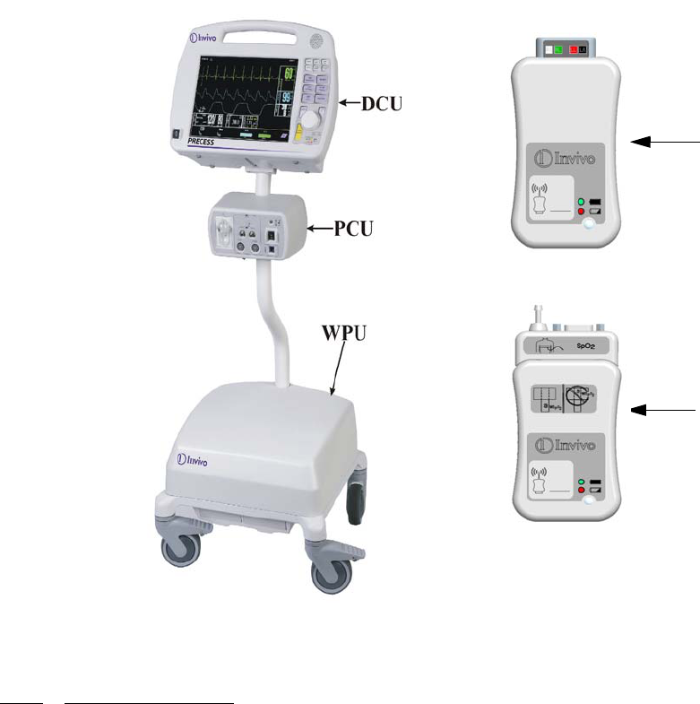
The Precess system consists of the following components (See Figure 1-1):
a. Wireless Processing Unit. The Wireless Processing Unit (WPU) houses the
circuitry and hardware for support of the standard and optional patient monitoring
parameters. The transceivers and antennas that support wireless communication
with the ECG and SpO2 modules as well as the Display Controller Unit are also
part of the WPU. The unit is powered by an AC – DC power adapter or two
removable batteries that are recharged by the same power adapter. The batteries
provide approximately 8 hours of continuous operation when NIBP, ECG, and
SPO2 parameters are runing at 5-minute intervals. Refer to section 2.5 for more
information.
b. Patient Connection Unit. The Patient Connection Unit (PCU) contains the
connectors that support all the non-wireless parameters (i.e. NIBP, ETCO2, etc.).
c. Display Controller Unit. The WPU communicates to the Display Controller Unit
(DCU) via a bi-directional 2.4 GHz communication link. The large color LCD
display, keypad, and recorder of the DCU form an easy-to-use user interface for
display, control, and documentation of the system patient monitoring parameters.
Indications for Use
The Precess MRI Patient Monitoring System is intended to monitor vital signs for patients
undergoing MRI procedures and to provide signals for synchronization of the MRI scanner.
The Precess MRI Patient Monitoring System is intended for use by health care professionals.
1-2
d. Wireless ECG Module. The Wireless ECG (WECG) module communicates two
leads of ECG simultaneously to the WPU. These two leads of ECG can be
displayed at the DCU and are output from the WPU unit for interface to the MRI
system cardiac gating input.
e. Wireless SpO2 Module. The Wireless SpO2 (WSpO2) communicates the SpO2
value and pulse waveform to the WPU. The information is available for display at
the DCU and is output from the WPU for interface to the MRI system pulse
peripheral gating input.
Figure 1-1. Precess Components
1.1.1 System Parameters. The Precess MRI Patient Monitoring System parameters allow
simultaneous processing and display of up to eight (8) parameters, six (6) waveforms, and
associated numeric values from each different parameter. All of the patient information is clearly
displayed on a flat panel display screen.
The Precess MRI Patient Monitoring System includes the following vital sign parameters:
• Dual Lead ECG • Pulse Oximetry (SpO2) • NIBP
• ETCO2 • Pneumatic Respiration • Anesthetic Agents
• Temperature • Invasive Pressure (IBP)
Wireless ECG
Module
Wireless SPO2
Module
1-3
1.1.2 User Interface. A simple-to-use interface has been developed to minimize operator
learning time. On the Display Control Unit (DCU), there is a Rotary Knob (which detents from
selection to selection) that is used to access the parameter menus, access the various setup features
and finalize any changes to the setup of the system. Frequently used menus (such as Alarms,
Trends and Recorder) have a Control Key which, when pressed, will open the associated menu.
1.1.3 Versatility. With its diverse offering of vital sign parameters, the Precess MRI Patient
Monitoring System may be configured to meet the monitoring needs of a wide spectrum of
patients from Neonate to Adults. Every available parameter may be easily accessed and adjusted
to the unique needs, condition and situation of each patient.
1.2 Wireless Processor Unit (WPU). The WPU contains wireless transceivers, data
acquisition and processing circuitry that communicate with the wireless Display Control Unit
(DCU), ECG (WECG) module and SpO2 (WSpO2) module.
1.2.1 Operating Environment. The WPU is designed to operate at the 5,000 Gauss line in the
generated RF field of an MRI system measured from the center line of the bore.
1.2.2 Power Supply. The WPU Power Supply is designed to operate on the floor at least 10 feet
from a 3.0 Tesla unshielded MRI system (200 Gauss). When attached, the power supply charges
the WPU (and DCU) battery packs whether the WPU is operating or not.
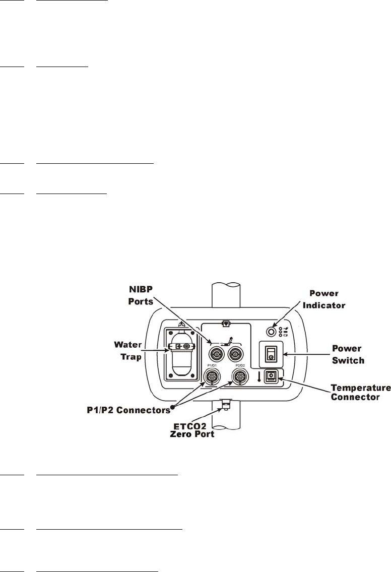
1.3 Patient Connections. The physical patient connections for NIBP, Invasive Pressure and
the Anesthetic Agents options are located on the Patient Connection Unit (PCU)
(
See Figure 1-2
)
.
ECG, SpO2 and Pneumatic Respiration all use wireless technology to deliver their measurements
to the Wireless Processor Unit (WPU).
Figure 1-2. Patient Connection Unit (PCU)
1.3.1 NIBP and Agent Monitoring. The PCU contains the physical connections for the Non-
Invasive Blood Pressure (NIBP) and, when installed, the optional Anesthetic Agents parameters.
If Anesthetic Agents is installed, the PCU also contains a water trap to prevent moisture
contamination of the agent components.
1.3.2 Invasive Pressure Monitoring. The PCU contains the physical connections for two
invasive pressure channels, P1 and P2. Use the recommended Invasive Pressure Transducers that
are listed in the Accessories Section page xvii.
1.3.3 Temperature Monitoring. The PCU contains the physical connection for one temperature
channel. This Temperature Connector is for use with the fiber optic probe or sensor listed in the
Accessories Section on page xvii. Temperature values are displayed in °C or °F, as selected by the
operator.
1.4 ECG Monitoring. ECG is monitored using a Wireless ECG Module (WECG). The
WECG module converts the ECG signals into radio signals for transmission to the Wireless
Processor Unit (WPU). The module also receives information through the wireless link, converts
the information to electrical signals and performs the commanded task (i.e. lead configuration
change, scaling, etc.).

1-4
•Compatibility. The WECG module supports the Quadtrode family of MRI
compatible ECG Electrodes.
•Visual Indicators. The WECG module contains one (1) bi-color LED that
indicates the status of the battery charge.
•Battery Life. The WECG module will operate at least eight (8) hours on a fully
charged battery.
1.5 SpO2 Monitoring. SpO2 is monitored using a Wireless SpO2 Module (WSpO2). The
Wireless SpO2 Module consists of a wireless transceiver to communicate with the Wireless
Processor Unit and convert the SpO2 pulse signal into radio signals for transmission to the
Wireless Processor Unit (WPU).
•Compatibility. The Wireless WSpO2 module utilizes a fiber optic SpO2 sensor.
•Visual Indicators. The WSpO2 module contains one (1) bi-color LED that
indicates the status of the battery charge.
•Battery Life. The WSpO2 module will operate at least eight (8) hours on a fully
charged battery.
1.6 Display Control Unit (DCU). The DCU provides control and display of the monitored
parameters.
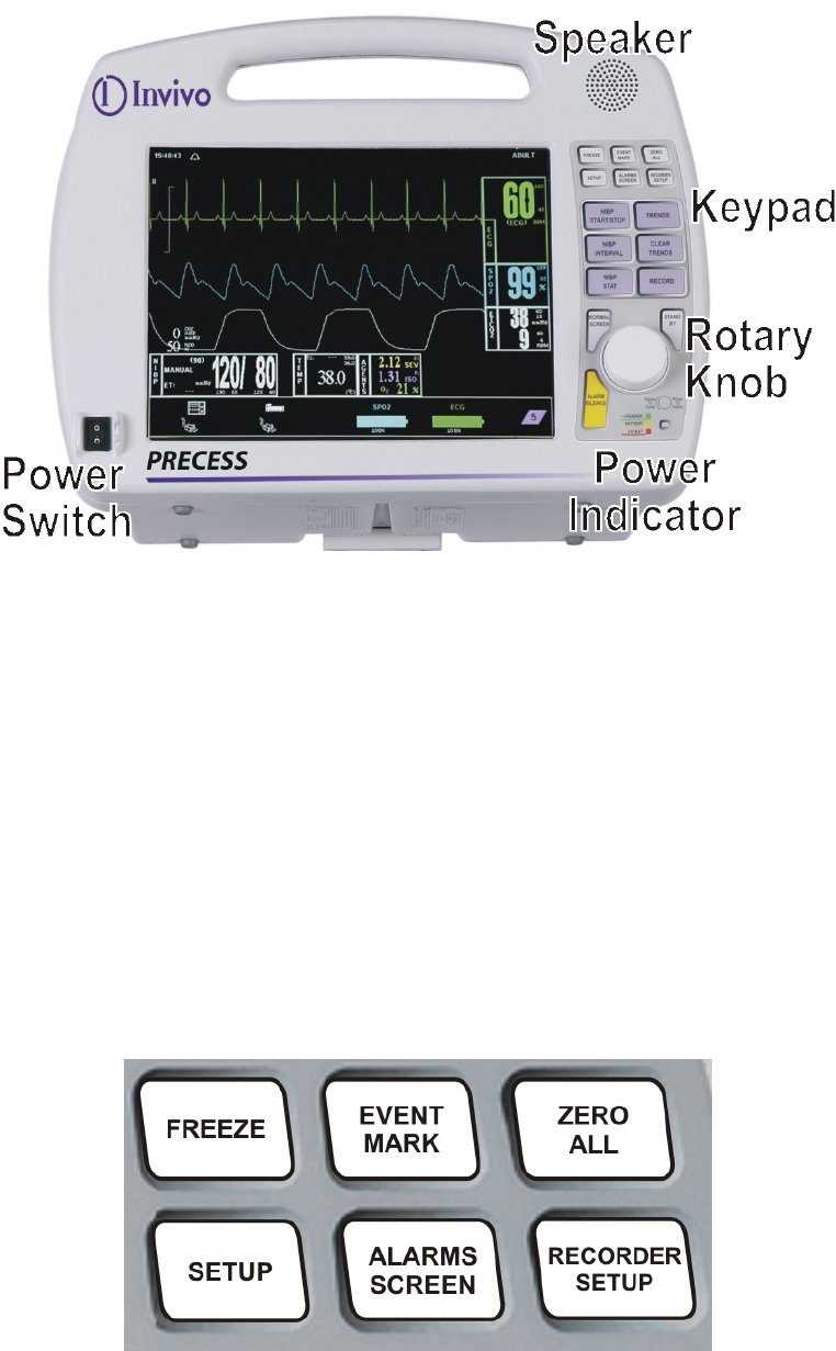
1.6.1 DCU Controls. (See Figure 1-3) The DCU front panel contains all the controls and access
for complete patient monitoring. Control is provided by the push button keys and Rotary Knob.
The Power Indicator is a three color LED that provides a visual indication of the DCU power
status with monitor power being turned off and on using the Power Switch. There is also a
Speaker to provide the sounds which the monitor produces and an Antenna for transmission/
reception of wireless signals. The following is a general description of the DCU.
a. The Rotary Knob. The Rotary Knob is located to the right of the Display Screen.
The function of the Rotary Knob is menu specific. For this reason, its various
functions are described throughout this document where it is used; in general,
however, the Rotary Knob operates as described below:
(1) As the Rotary Knob is rotated, either clockwise or counterclockwise, the
DCU display “scrolls” through the various screen items (screen icons,
menu options and patient parameters) which are available for selection.
When the appropriate item is “highlighted,” it may be selected by pressing
and releasing the Rotary Knob. All menus have a RETURN option which
will return the display to the previous menu selection.
1-5
Figure 1-3. The DCU Front Panel
(2) During normal operation each active parameter has a Menu-Select icon on
the DCU display. When the Rotary Knob is rotated, the Menu-Select icon
which is being pointed at becomes “highlighted.” Rotating the Rotary
Knob will cause the display to “scroll through” the available menu
selections. Once the appropriate Menu-Select icon is highlighted, pressing
the Rotary Knob completes the selection and brings up the required menu.
Once the menu is selected, the Rotary Knob is used to scroll through the
available menu choices and make adjustments to the selected parameter.
The following Menu-Select Icons may be available on the Normal Screen
(depending on which parameters are available, enabled and turned on):
ECG, NIBP, SpO2, ETCO2, Agents, Invasive Pressures, and Temperature.
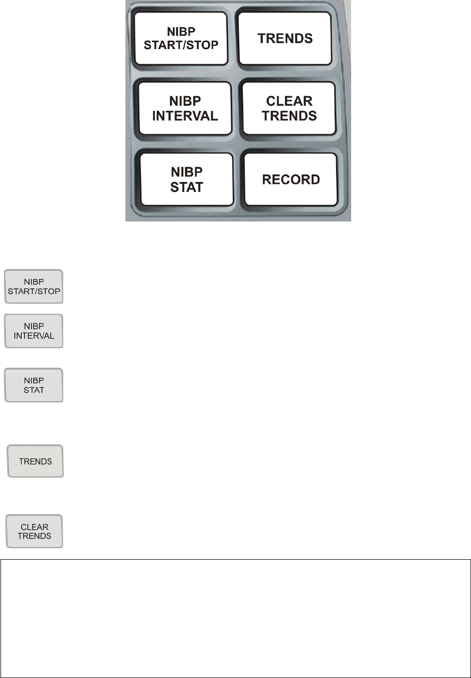
b. The Top Keypad Set. (See Figure 1-4) There are six push keys in the top keypad
set. The top three (FREEZE, EVENT MARK and ZERO ALL) provide direct
control of a system feature while the bottom three (SETUP, ALARMS SCREEN
and RECORDER SETUP) provide access to operational menus. The six push keys
are described below.
Figure 1-4. The DCU Top Keypad Set

1-6
:
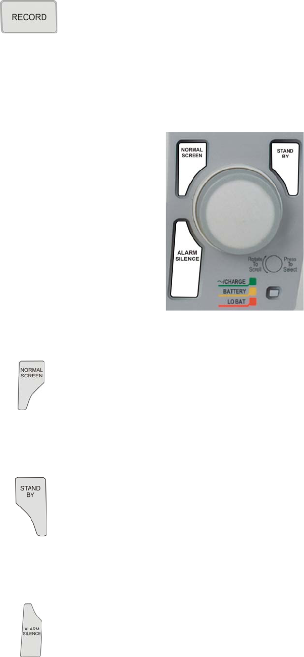
c. The Middle Keypad Set. (See Figure 1-5)The middle keypad set contains six
push keys. The three on the left provide control of the NIBP monitoring feature
with two of the keys (NIBP START/STOP and NIBP STAT) providing direct
control of NIBP measurements and the third (NIBP INTERVAL) bringing up a
menu that allows adjustment of the NIBP Auto Mode Interval feature. On the right
side of this set are two keys which control the Trending feature of the monitor
(TRENDS and CLEAR TRENDS) while a third (RECORD) provides a hardcopy
printout of selected parameters as specified by operator adjustments in the
Recorder Menu. The six push keys are described below.
(1) FREEZE. The Precess MRI Patient Monitoring System freezes the ECG
waveform from Trace A for closer examination upon user demand. When
the ECG trace is active, pressing the FREEZE key will freeze it into the
Trace B location while Trace A remains active. When the trace is frozen,
pressing the FREEZE key will release it. A “Blue Box” appears around the
frozen waveform as a visual indication that the waveform is not active.
While the Freeze feature is active, the monitor will not allow any changes
to the Parameter Setups or Display; if the operator attempts to access the
Parameter Selection Menu, a WARNING Box alerts the operator that entry
to the selected menu is not allowed while FREEZE is Enabled.
(2) EVENT MARK. The EVENT MARK key prints a marker on the ECG
Recorder Strip when the printer is running. If the printer is not running,
pressing this key has no effect.
(3) ZERO ALL. The ZERO ALL key initiates a zero of the pressure
transducer of all available invasive pressure channels.
(4) SETUP. The SETUP key allows the operator to access the various
available setup options.
(5) ALARMS SCREEN. The ALARMS SCREEN key is a dual function key
that allows the operator to setup the Alarms monitoring feature. When the
monitor display is in the Normal Screen and the ALARMS SCREEN key
is pressed, the Main Alarm Setup Screen will appear. When the monitor
display has any icon highlighted and the ALARMS SCREEN key is
pressed, an Alarm Setup Screen for the highlighted parameter appears.
(6) RECORDER SETUP. The RECORDER SETUP key allows the operator
to setup the Recorder option.
1-7
Figure 1-5. The DCU Middle Keypad Set
(1) NIBP START/STOP. This key starts a new NIBP measurement, or stops a
measurement that is already in progress.
(2) NIBP INTERVAL. Pressing the NIBP INTERVAL key brings up the NIBP
Interval Menu where the cycle time (time between readings) of the NIBP
Automatic Reading Mode may be adjusted.
(3) NIBP STAT. This key starts the NIBP STAT Mode measurements. This
mode may be terminated by depressing the NIBP START/STOP key. The
STAT Mode performs up to five (5) NIBP measurements in rapid
succession (with a short pause between readings) within a maximum time
frame of five (5) minutes.
(4) TRENDS. The TRENDS key allows the operator to setup the Trend
monitoring feature. The exact operation of the TRENDS key is based on
whether or not a feature is currently highlighted. If a feature is currently
highlighted, pressing the TRENDS key will bring up a Trend which is
specific to the highlighted feature; if a feature is not currently highlighted,
pressing the TRENDS key will bring up the History Menu and Tabular
Display (See Section 5).
(5) CLEAR TRENDS. Pressing the CLEAR TRENDS key allows the operator
to clear all the stored data from memory. To prevent accidental erasure of
patient data, there is a YES/NO box associated with this key that appears to
ensure that the operator meant to clear the trend data.
NOTE
In various menus, the operator may accidentally make a selection that has significant
irreversible effects (e.g.: erasing patient data). To protect against such accidents a
Yes/No Menu is associated with these selections. This menu has only two active
selections: YES and NO. The operator must select one of the two choices to either
confirm the change to take place, or to cancel it. A delay of approximately 30 seconds
without any selection is equivalent to selecting NO. The Yes/No Menu is removed upon
operator selection, at the end of the time-out feature, by pressing the NORMAL
SCREEN button or by pressing the STANDBY button.
1-8
d. The Bottom Keypad Set. (See Figure 1-6) The bottom keypad set is not grouped
like the top and middle, but is grouped around the Rotary Knob. There are three
push keys in this set (NORMAL SCREEN, STANDBY and ALARM SILENCE)
which provide direct control of operational features of the system. The three push
keys are described below.
.
Figure 1-6. The DCU Bottom Keypad Set
(6) RECORD. Pressing this key records the Single Trace or Dual Trace
selections (as specified by operator adjustments made in the Recorder
Menu).
The recorder stops automatically after approximately 30 seconds, or when
the RECORD key is pressed again; in either case, the printout ends with a
“Snap Shot” of the active patient parameter data.
(1) NORMAL SCREEN. Pressing the NORMAL SCREEN key returns the
Precess MRI Patient Monitoring System from any menu to the Normal
Screen.
(2) STANDBY. Pressing the STANDBY key places the Precess MRI Patient
Monitoring System into the Standby Mode. The system stays in Standby
Mode until the STANDBY key is pressed a second time. Except for the
three (3) key features given below, the system operates normally by
continuing to provide current patient information on the display screen.
While in Standby Mode:
• All audible alarms are disabled. The disabled alarms are indicated
on the screen by the “X” through the bell shaped Alarm Status
Symbol.
• Active NIBP automatic measurements and STAT Mode
measurements are suspended.
• No automatic printout is generated.
• Default NIBP inflation pressures will be used for all manual NIBP
readings.
(3) Alarm Silence Key. Pressing the ALARM SILENCE key, when the
audible alarms are enabled (as denoted by the absence of the “X” through
the bell shaped Alarm Status Symbol), will affect the system as described
below:
1-9
(a) Alarm Silenced. Any new alarm conditions will cause the Alarm to
reactivate.
In addition, while alarms are silenced the following conditions
apply:
•Unlatched Alarms. If the alarm system has been set to
UNLATCHED in the Alarms Menu and an Alarm Limit is
violated, pressing the ALARM SILENCE key will silence
the Alarm Tone and put the letter “S” in the Alarm Bell.
While the parameter continues to violate its limits, the
numerics of the violating parameter continue to flash in red
on the screen. Once the parameter returns to within its
Alarm Limit, the numerics return to their designated color
and no longer flash.
•Latched Alarms. If the alarm system has been set to
LATCHED in the Alarms Menu and an Alarm Limit is
violated, while the parameter continues to violate its limits,
pressing ALARM SILENCE key stops the Alarm Tone, but
the numerics remain red and continue to flash, even after the
parameter returns to within its Alarm Limits.
•ALARM HOLD. If the ALARM SILENCE key is pressed
when the Alarm Tone is Enabled but no alarm condition
currently exists, a “SOUND ON HOLD” message appears
in the upper center of the display with a count down timer
starting at 120 (counting down at a 1 second rate) denoting
that the Alarm Tone is being temporarily held silent. In
addition, an “H” will appear in the Alarm Status Symbol to
further alert the operator that the Alarm System is on Hold.
If the Alarm Tone is sounding, the first pressing of the
ALARM SILENCE key stops the Alarm Tone, and puts the
letter “S” in the Alarm Bell, and a second press Enables
ALARM HOLD.
The system automatically exits ALARM HOLD after two
minutes (120 seconds), and the “SOUND ON HOLD”
message disappears from the display, reactivating the Alarm
Tone. Remember that a current alarm condition (which has
been silenced) will not sound again unless the condition
returns within limits and then violates the limit again. Also
remember that a silenced alarm may not be accompanied by
the Alarm Silence message. Pressing the ALARM
SILENCE key before the two minute period is over will
also reactivate the Alarm Tone and remove the “SOUND
ON HOLD” message from the display. The duration of the
Sound On Hold feature is not user adjustable, and has a
predefined value of two minutes (120 seconds).
The user is able to put Alarms on Hold (SOUND ON
HOLD) only when the Alarm Tone is active (no X appears
in the bell symbol in the upper left of the display). Alarm
Hold is useful for temporarily disabling the Alarm Tone.
This might be useful, for example, when changing ECG
leads or for any user activity which might cause a “false”
alarm.

1-10
(b) Front Panel Communication Power Light. (See Figure 1-6.) The
Front Panel Power Light (located beneath the Rotary Knob) is a
three color LED that indicates the AC/Battery Power condition of
the monitor. The Power Light will illuminate Green, Yellow and
Red as described below:
•Green Light. A SOLID GREEN Light indicates that the
monitor is on AC power, the power switch is ON, the unit
has good communications with a WPU, and if batteries are
inserted they are charging. SLOW BLINKING GREEN
(1 per 2.5 seconds) indicates that the monitor is on AC
power, power switch is OFF, and if batteries are inserted
they will be charging. FAST BLINKING GREEN
(1 per. 6 seconds) indicates the unit is on AC power, the
power switch is ON, there are no communications, and if
batteries are inserted they will be charging.
•Yellow Light. A SOLID YELLOW Light indicates the unit
is on battery power, the power switch is ON, and the unit
has good communications with a WPU. FAST BLINKING
YELLOW (1 per. 6 seconds) indicates the unit is on battery
power, the power switch is ON, and there are no
communications.
•Red Light. A RED Light indicates WARNING because
WPU and/or DCU shutdown is soon to occur. The internal
batteries have fallen below the required operational output
and an AC Wall Outlet must be located, and the system
plugged into it through the AC Power Adapter,
immediately. SOLID RED indicates the unit has a low
battery condition, the power switch is ON, and the unit has
good communications with the WPU. FAST BLINKING
RED (1 per. 6 seconds) indicates that the unit has a low
battery condition, the power switch is ON, and there are no
communications.
•No Light. NO LIGHT indicates that the unit is on battery
power and the power switch is OFF.
1.6.2 DCU Display. (See Figure 1-7.) The DCU Display Screen displays four groups of data:
The Informational Display, Vital Signs Trace Display, Vital Signs Numeric Display, and Status
Display. The entire display screen with its four different display groups is called the “Normal
Screen”. The four display areas are described below.
WARNING
An active silenced alarm may not be accompanied by an Alarm Silence message
or an “S” in the Alarm Bell icon if the Alarm Hold sequence has been activated,
or if a subsequent additional alarm has occurred and self-corrected.
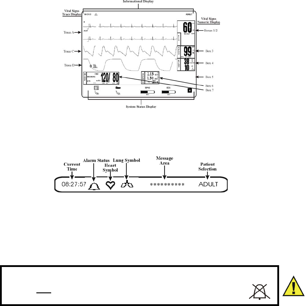
1-11
Figure 1-7. The DCU Normal Screen
a. Informational Display. (See Figure 1-8) The Informational Display is located at
the top of the Normal Display. This display provides the operator with the current
time, the Alarm Status Bell Symbol, a flashing Heart Rate Symbol, a flashing
Lung Symbol, any current user messages and the current Patient Selection.
Figure 1-8. The DCU Informational Display
(1) Time. The current time is displayed in a 12 or 24 hour format (hh:mm:ss).
The time, date and clock mode (12 or 24 hour) is adjusted in the SET TIME
Menu.
(2) Alarm Status Symbol. The Precess MRI Patient Monitoring System
sounds an Alarm Tone when any monitored parameter violates its
programmed Alarm Limits. The status of the Alarm Tone is indicated by
the bell shaped Alarm Status Symbol.
(a) The letter “H” appearing in the bell indicates that the alarms have
been placed on temporary HOLD with the ALARM SILENCE key.
Similarly, during power-up the “SOUND ON HOLD” message
displayed in the center of the screen indicates that the Alarm Tone
is temporarily placed on HOLD. A 120 second countdown timer is
also displayed under the message.
(b) The letter “X” appearing in the bell symbol indicates that the
alarms have been turned OFF from the ALARMS Menu or that
Standby Mode has been engaged. In this case the Alarm Tone will
not sound for any reason.
WARNING
When an “X” appears in the Alarm Status Symbol, the audible Alarm
Tone will NOT sound for any reason.
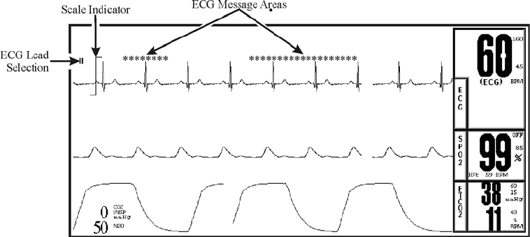
1-12
(c) The letter “S” appearing in the bell indicates that a current alarm
has been silenced with the ALARM SILENCE key. This feature
will disable only the alarms that were current when the ALARM
SILENCE key was pressed, any new alarms will cause the Alarm
Tone to sound.
(3) Heart Symbol. The Heart Symbol flashes on the screen each time a heart
beat is detected. A tone is sounded at the same time (unless turned off in
the ECG Menu or the SPO2 Menu).
(4) Lung Symbol. The Lung Symbol flashes on the screen at the end of each
detected breath whenever the ETCO2 monitoring feature is turned ON.
(5) Messages. These messages assist the operator in various aspects of the
operation of this monitor.
(6) Patient Selection. Indicates the selected patient (ADULT or NEONATAL).
b. Vital Signs Trace Display. (See Figure 1-9.) The Vital Signs Trace Display is
located in the middle of the Display Screen. This display provides the operator
with a trace of the selected parameters and also contains Numerical Vital Sign
indications for the selected patient parameter.
Figure 1-9. The DCU Vital Signs Trace Display
(1) The Vital Signs Trace Display portion of the screen is divided into six
separate trace areas. When turned on, the traces are fixed on the screen and
updated with an Erase Bar. When a Trace has been turned OFF, that portion
of the screen is blank. The numeric values for each Trace appear near the
right screen boundary.
(2) If the value is greater than or equal to a maximum calculable value, “OVR”
(Over Range) is alternately displayed with the numeric value.
(3) TRACE A, C and D are assigned according to parameter and come on/go
off as parameters are turned on or off. Trace B is the location used for the
“Freezing” of a waveform and is also used for ECG 2.
• TRACE 1 = ECG1
• TRACE B = ECG2/Freeze ECG1
• TRACE C = SpO2
• TRACE D = ETCO2/Agents Waveform
• TRACE E = P1
• TRACE F = P2
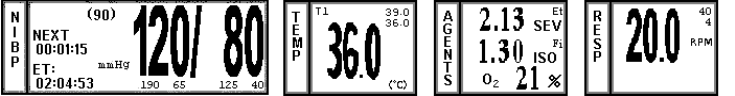
1-13
The following is a description of each Trace:
(a) TRACE A. The ECG trace is displayed in this position, unless
turned Off from either the ECG Menu or the Setups Menu. The
main menu for this trace and for the Heart Rate are brought up with
the selection of the ECG Menu-Select Icon.
• The Heart Rate is displayed near the right screen boundary
in the Trace A position. The numerics turn RED and flash if
a Heart Rate Alarm Limit is violated. The color of the
numerics is that of the selected HR Source.
• The annotation below the Heart Rate value indicates the
Source of the Heart Rate, as selected from the ECG Menu,
the NIBP Menu and the SPO2 Menu. Heart Rate Source
choices are AUTO, ECG, SPO2, ART and NIBP.
• A RED flashing numeric value on the screen indicates that
an alarm for this value has been violated. This provides a
visual indication of alarm violations, even when the Alarm
Tone is turned OFF.
• If AUTO is selected as the HR SOURCE, the highest
priority active input is utilized for displaying the Heart Rate,
in the order listed above. The ECG Trace must be OFF, or
Lead Fail present, for the Auto Source not to be the ECG
Trace.
• If the system does not find a valid Heart Rate Source when
set to AUTO and NIBP is OFF, the heart rate is annotated
with “NONE.”
• The displayed Lead for the ECG 1 is indicated near the left
screen boundary.
• A Scale Indicator is displayed near the left screen boundary
in the ECG waveform area(s). It represents a 1mV
amplitude in the currently selected Scale.
(b) TRACE B. Trace B displays ECG 2 or a frozen waveform for
detailed analysis.
(c) TRACE C. Trace C displays the SpO2 waveform (if SpO2
Enabled).
(d) TRACE D. Trace D displays the Respiration waveform (if ETCO2
enabled).
c. Vital Signs Numeric Display. (See Figure 1-10.) The Vital Signs Numeric
Display is located at the bottom and right of the display screen. This display is
divided with boxes that provide the operator with numerical indications for NIBP,
Temperature, RESP, and Agents.
Figure 1-10. The DCU Vital Signs Numeric Display
The following is a description of the NIBP, Temperature, RESP, and Agents boxes.
1-14
(1) Non-Invasive Blood Pressure (NIBP). NIBP is the first parameter (from
the left) displayed in the Vital Signs Display. The Systolic, Diastolic and
Mean blood pressure values are displayed along with measurement
information such as the Elapsed Time (ET) since the last measurement and
the time until the next measurement (if in the Automatic Mode). While in
the Manual mode, MANUAL is shown in the place of the time until the
next measurement.
During a reading cycle the current cuff pressure is displayed (“CUFF:
XXX”).
Between the measurements the elapsed time (time since the last reading) is
displayed (ET= 00:00:00) instead of the cuff pressure.
The NIBP error messages are shown in place of the “NEXT: 00:00:00.”
If errors are detected by the NIBP circuitry, one of the following messages
are displayed which preclude the determination of the blood pressure:
(a) OVER PRES: Cuff inflation pressure has exceeded 280 ±5 mmHg.
(b) CALIB: The system detected DC offset below 1 mmHg or above
11 mmHg.
(c) NOT INFLATING: Cuff inflation runs longer than 30 seconds.
(d) LONG PRES: Cuff pressure remains at one level for more then
30 seconds.
(e) CUFF LEAK: The cuff inflation pump has run for more than
20 seconds. Check hose and cuff connections.
(f) RESID PRES: Cuff pressure above 20 mmHg for more then
180 seconds.
(g) WRONG CUFF: The wrong cuff is attached for the patient setting.
Select ADULT or NEO (as appropriate) in the Setups Menu.
(2) Temperature. The Temperature box is the second parameter (from the left)
displayed in the Vital Signs Display area. The Temperature box provides
display of the patient temperature. If the Temperature reading is below
20.0 degrees C (69.8 degrees F), the display will show “UND”. If the
Temperature reading is over 44.0 degrees C (111.2 degrees F), the display
will show “OVR”. If the temperature sensor is not plugged into the
temperature sensor input on the PCU, the display will show “---”.
(3) Pneumatic Respiration. The Pneumatic Respiration box is the fourth
parameter (from the left) displayed in the Vital Signs Display area. This
box displays the numeric value of the patient Respiration rate measured in
the Respiration Per Minute (RPM). The Respiration rate is measured by a
pneumatic bellows belt that is placed around the patient’s chest. As the
patient breathes, the movement of the chest modulates the air inside the
pneumatic bellows. The Respiration rate is calculated by analyzing the air
signal at the bellows. Note that a waveform of the Pneumatic Respiration is
not available.
(4) Agents. The Agents box is in the middle of the Normal Screen. This box
displays the numerical values for N2O, anesthetic agents Sevoflurane,
Isoflurane, Desflurane, Halothane, and identifies the presence of anesthetic
agent Enflurane. Five gases are identified and specified by name next to the
numerical value for the gas being measured. A numeric value will not be
displayed for Enflurane.
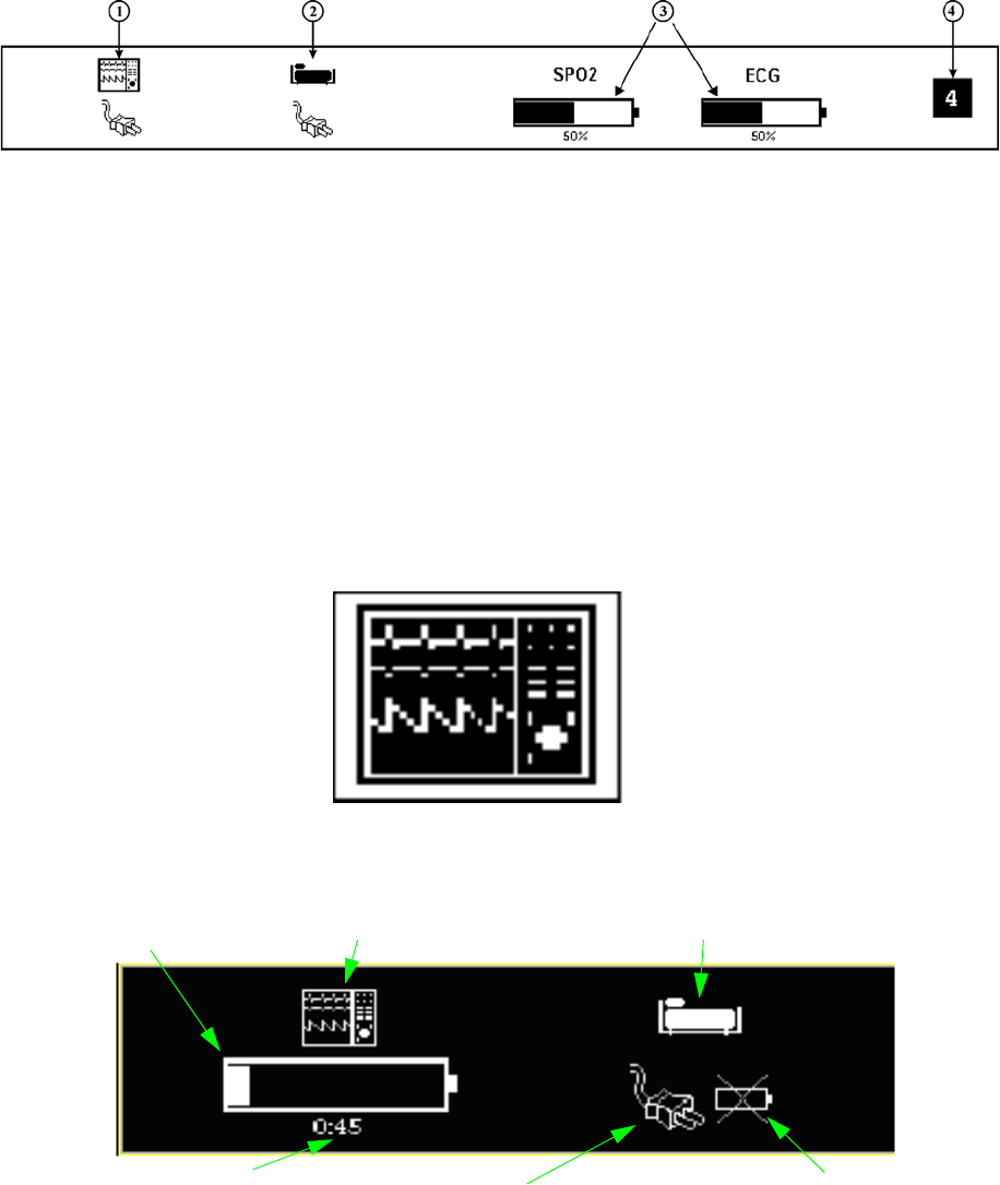
1-15
d. Wireless System Status Display. The System Status Display (Figure 1-11) is
located at the bottom of the Normal Screen Display and provides the operator with
visual indications of the operational status of the system. From left to right, the
symbols represent DCU Power Status (1), WPU Communication-Power Status (2),
SPO2 Communication-Battery Status (3), ECG Communication-Battery Status
(3), and the Communication Network Indication (4).
Figure 1-11. Wireless System Status Display
(1) DCU Power Status (1). The DCU Power Status area is donated by the
DCU symbol (Figure 1-12). Below the DCU Symbol are indicators that
show the power status for that particular DCU. When the DCU is operating
from line power, the AC Power Cord Icon is displayed as in Figure 1-11. If
batteries are not installed in the DCU, then the Battery Not Installed Icon
(Figure 1-13) is displayed just to the right of the AC Power Cord Icon.
When the DCU is operating from battery power, a Battery Gauge Icon
indicating the amount of time remaining on the battery power is displayed
(Figure 1-13). The numeric display of the amount of time remaining is
formatted as “hours:minutes” and is updated in 15 minute increments.
When less than thirty (30) minutes of operating time remains, the numeric
Time Remaining Display will disappear, the message “LOW” will appear
in the Battery Gauge Icon, the Battery Icon will flash in the color RED, and
an audible tone will be output.
Figure 1-12. DCU Symbol
.
Figure 1-13. Example of Power Indicator Symbols (DCU & WPU)
Battery Symbol DCU Indicator WPU Indicator
Battery life remaining
in hours: minutes
On AC Power Battery Not Installed (appears
only when battery not in unit)

1-16
(2) WPU Communication-Power Status (2). The WPU Status area is
denoted by the WPU symbol (Figure 1-14). When this symbol is present,
good communication has been established between that DCU and the
WPU. When communication is lost or has not been established between the
DCU and the WPU, the WPU symbol with the slashed enclosure (Figure
1-15) will be displayed. Below the WPU Symbol are indicators that show
the power status for that WPU. When the WPU is operating from line
power, the AC Power Cord Icon is displayed (Figure 1-13). If batteries are
not installed in the WPU, then the Battery Not Installed Icon (Figure 1-13)
is displayed just to the right of the AC Power Cord Icon. When the WPU is
operating from battery power, a Battery Gauge Icon indicating the amount
of time remaining on battery power is displayed (Figure 1-13). The
numeric display of the amount of time remaining is formatted as
“hours:minutes” and is updated in 15 minute increments. When less than
thirty (30) minutes of operating time remains, the numeric Time
Remaining Display will disappear, the message “LOW” will appear in the
Battery Gauge Icon, the Battery Icon will flash in the color RED, and an
audible tone will be output.
Figure 1-14. WPU Display Symbol
Figure 1-15. WPU No Communication Display
(3) SPO2 and ECG Communication-Battery Status (3). The SPO2 and
ECG Communication-Battery Status areas are denoted by the SPO2
symbol and ECG symbol (Figure 1-16). These symbols represent the
Wireless SpO2 and Wireless ECG Modules. Below the SPO2 and ECG
Symbols are the SPO2 and ECG Battery Gauge Icons that indicate the
amount of capacity remaining in each battery. The Wireless SpO2 and
Wireless ECG Modules will operate for eight (8) hours when the battery
gauge shows full (100%) capacity. An indication of 75% will provide
approximately six (6) hours of operation, 50% approximately four (4)
hours, 25% approximately two (2) hours, and 12% approximately one (1)
hour. When less than thirty (30) minutes of operating time remains, the
numeric time remaining will disappear from the display, the message
“LOW” will appear in the Battery Gauge Icon, the Battery Icon will flash
in the color RED, and an audible tone will be output. When communication
is lost or has not been established between the Wireless SpO2 Module and
the WPU, the SPO2 Symbol will become large in size and will be
surrounded by the slashed enclosure (Figure 1-17). Likewise, when
communication is lost or has not been established between the Wireless
ECG module and the WPU, the ECG Symbol will become large and will be
surrounded by the slashed enclosure (Figure 1-17).
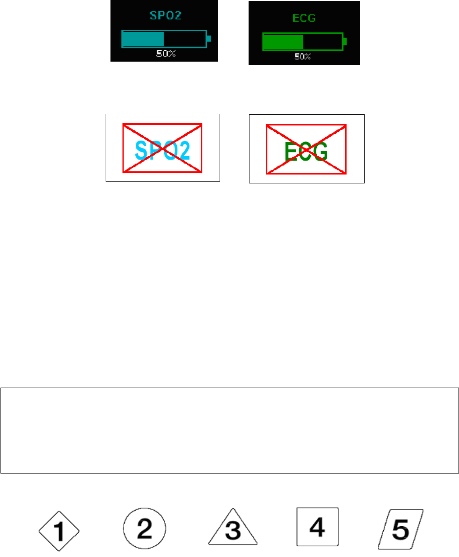
1-17
Figure 1-16. Wireless SpO2 and ECG Battery Symbols
Figure 1-17. Wireless SpO2 and ECG No Communication Display
(4)
Communication Network Indication (4).
The Communication Network
Indication Symbol provides the wireless communication network
designation for the particular Precess system. In order for the Precess
system to properly communicate with all components (DCU, WPU,
Wireless SpO2 and ECG Modules), the Network Designators (
Figure 1-18
)
on each system component must be the same. Each Network Designator has
its own characteristic color, shape, and number in order that each designator
is easily distinguishable. In areas where multiple Precess systems are being
utilized, it is extremely important that each component within a system is
set to the proper network, otherwise a component on the wrong network
will interfere with another system or incorrect patient vital signs
information will be obtained and displayed.
.
Figure 1-18. Network Designators
NOTE
In environments where multiple Precess systems are being utilized, the operator must
be aware of each system’s network setting. Operating on the same or wrong
communication network will interfere with another system or incorrect patient vital
signs information will be obtained and displayed. Figure 1-18 shows each
Communication Network Designator.
Network 1 Network 2 Network 3 Network 4 Network 5

e. Yes/No Menu. In various menus, the operator may accidentally make a selection
that has significant irreversible effects (e.g.: erasing patient data). To protect
against such accidents a Yes/No Menu is associated with these selections. This
menu has only two active selections: YES and NO. The operator must select one of
the two choices to either confirm the change to take place, or to cancel it. A delay
of approximately 30 seconds without any selection is equivalent to selecting NO.
The Yes/No Menu is removed upon operator selection, at the end of the time-out
feature, by pressing the NORMAL SCREEN button or by pressing the STANDBY
button.
1.7 Cleaning. The system is not sterilizable. Never immerse any part of the system in any
fluid or attempt to clean it with liquid cleaning agents. Remove dirt and dust from the DCU,
WPU, and/or modules by wiping it with a soft, damp cloth.
Stains can be removed from the DCU, WPU, and/or module housings by scrubbing briskly with a
damp cloth. Unplug the system and remove the batteries before cleaning. Do not permit liquid to
contact the front or rear of the DCU, or permit liquid to drip into the printer or around display
screen. If liquid entersmust any components, contact Invivo Technical Support.
1.7.1 Cleaning Accessories. Any reusable patient accessories must be cleaned after each use.
Disposable patient accessories mustwill be discarded and replaced with new items.
To clean reusable accessories, first, remove the accessory from use. Remove any dirt or debris
using soap and water. Avoid immersing accessory in any fluid for cleaning.
Inspect the accessory for any cracks, holes, tears, cuts, etc., that could affect operation, and
replace as necessary.
If disinfection is required, use only the recommended liquid surface disinfectants, unless
otherwise specified in the accessories listing. Recommended surface disinfectants include dilute
solutions of either quaternary ammonium compounds, iodophors or gluteraldehydes.

2-1
SECTION 2
INSTALLATION
2.0 INSTALLATION
2.1 Unpacking The System. Remove each system component from the shipping boxes and
carefully examine all components for damage that may have occurred during shipment. Check all
items against the included packing list and purchase request. To resolve any issues or concerns
with your order or product, or to report shipping damage, contact Invivo Customer Service. Save
all packing materials and related shipping documents, as these will be required to process a claim
with the carrier if damage during shipment occurred.
2.2 System Configuration. Before proceeding, read the Precautions and User Responsibility
Sections (Pages v to xvi.). These sections provide important safety information. The standard
Precess MRI Patient Monitoring System consists of one (1) WPU, one (1) DCU, one (1) WECG
module, and one (1) WSpO2 module. The DCU attaches to the WPU by sliding the DCU onto the
WPU Power-Mounting Shoe. When installed in the WPU Power-Mounting Shoe, the DCU
receives power from the WPU. With the WPU connected to line power and the DCU installed in
the Power-Mounting Shoe, the DCU batteries are charged through the WPU. For added flexibility,
the system can be configured with two (2) additional DCUs, for a total of three (3) DCUs. These
DCUs can be located either inside the MRI exam room, inside the MRI control room, or in an
MRI holding area.
2.3 Battery Installation and Removal. All batteries can be removed and installed into their
respective unit at any time. Note that the operation of the WECG and WSpO2 will be interrupted
when the batteries are removed. Likewise, the operation of the WPU and DCU will be interrupted
if the batteries are removed and the unit(s) is/are not powered by a power supply. The WECG and
WSpO2 batteries (Part Number 9065) are completely non-magnetic and can be removed and
replaced from the wireless modules while in the MRI magnetic field; however, the batteries must
be kept out of the Field of View, otherwise image artifact can occur.
2.3.1 Battery Locations.The WPU has two batteries (Invivo Part Number 9064 or 9093) that are
located on the bottom front of the unit (Figure 2-1). The DCU also has two batteries (Invivo Part
Number 9064 or 9093) that are located on each side of the unit (Figure 2-2). Note that the WPU
and DCU batteries are interchangeable. The WSpO2 and WECG modules each have a battery
(Invivo Part Number 9065) located on the back of the units (Figure 2-3 and Figure 2-4). Note
that the WECG and WSpO2 batteries are also interchangeable.
NOTE
The 9065 battery and wireless module must not be placed in the Field of View to
minimize the chance of image artifact.
CAUTION
Prior to clinical use, the operator must be aware of the minimum distance from the MRI
System for proper operation.
The WPU and DCU batteries (Part Number 9064 or 9093) contain some ferrous
materials that are attracted to the MRI magnetic field. DO NOT remove the batteries
from the WPU or DCU when these units are closer than the 1,000 Gauss line
(0.1 Tesla) as the batteries will be attracted to the magnetic field, thus causing patient
or user injury.
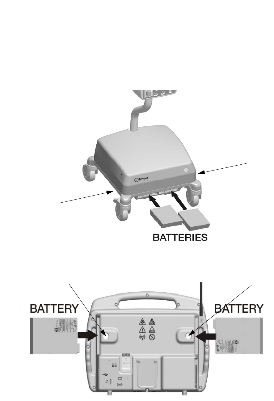
2-2
2.3.2 WPU And DCU Battery Installation And Removal.The WPU and DCU batteries slide
into their respective battery compartments and automatically latch into place. When installing the
batteries, note that they must be orientated properly into the battery compartment in order that
they will latch into place. The battery packaging is designed such that the battery fits the contour
of the unit geometry. If the battery does not latch automatically into place when fully inserted into
the battery compartment, then the battery is probably not orientated properly. Orientate the battery
in the other direction and reinstall the battery into the battery compartment. Never force a battery
into the battery compartment as it will damage the battery or the Precess MRI Patient Monitoring
System. In order to remove a battery from the WPU or DCU, simply press the associated Battery
Eject Button and that battery will partially eject for easy removal (see Figure 2-1 and Figure 2-
2). Refer to the Caution below regarding battery disposal.
.
Figure 2-1. WPU Battery Location
Figure 2-2. DCU Battery Locations
Battery Eject Button
(On Underside)
Battery Eject Button
(On Underside)
Battery Eject Button
Battery Eject Button
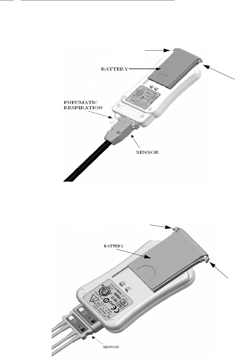
2-3
2.3.3 WECG And WSpO2 Battery Installation And Removal. The wireless module batteries
each slide into the battery slots on the WECG and WSpO2 modules and latch into place on each
side. To remove the batteries, use your fingers to simultaneously press the latches on both sides of
the battery and the battery will slide out of the module (see Figure 2-3 and Figure 2-4). Refer to
the Caution below regarding battery disposal.
Figure 2-3. WSPO2 Module Battery Location
Figure 2-4. WECG Module Battery Location
Battery Latch
Battery Latch
Battery
Latch
Battery Latch

2-4
.
WARNING
• Stop using the battery if it exhibits abnormal heat, odor, color, deformation or
is in an abnormal condition.
• If punctured or liquid leaks onto your skin or clothes, wash well with fresh
water immediately.
• If liquid leaking from the battery gets into your eyes, do not rub your eyes.
Wash them well with clean water and consult a doctor immediately.
CAUTION
• Never heat the battery nor throw into a fire. Keep the battery contacts away from metal
objects.
• Replace batteries with only Invivo supplied batteries. Refer to the Accessories list on
page xvii.
• Store battery in a dry place, 0°C to 40°C.
• Dispose of battery properly*.
• Do not disassemble or incinerate battery.
• Charge battery before use.
• Batteries have life cycles, so if the time that the battery is powering the equipment
becomes much shorter than usual, the battery life is at an end. Replace the battery with
a new one.
• Remove a battery whose life cycle has expired from equipment immediately.
• If the terminals of the battery become dirty, wipe them with a dry cloth before using the
battery.
* Disposal in Europe: The European Community (EC) has issued two directives; 91/157/
EEC and 93/86/EEC. Each member country implements these independently. Thus, in
each country the manufacturers, importers and users are responsible for the proper
disposal or recycling of batteries.
* Disposal in the US: Lithium batteries are neither specifically listed nor exempted from
the Federal Environmental Protection Agency (EPA) hazardous waste regulations, as
conveyed by the Resources Conservation and Recovery Act (RCRA). The only metal of
possible concern in the cell is the lithium metal that is not listed or characterized as a toxic
hazardous waste. Significant amount of spent cells and batteries that are untreated and
not fully discharged are considered as reactive hazardous waste. Thus, hazardous waste
of spent cells and batteries can be disposed after they are first neutralized through an
approved secondary treatment prior to disposal (as required by U.S. Land Ban Restriction
of the Hazardous and Solid Waste Amendments of 1984). Disposal of spent batteries must
be performed by authorized, professional disposal company, which has the knowledge in
the requirements of the Federal, the State and the Local authorities regarding hazardous
materials, transportation and waste disposal. In any case it is recommended to contact the
local EPA office.
CAUTION
All batteries must be removed prior to shipping the Precess MRI Patient Monitoring
System.
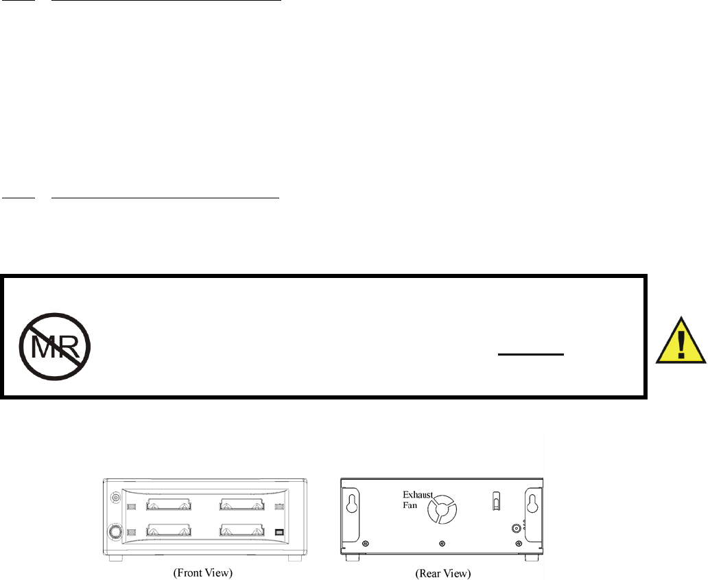
2-5
2.4 Battery Charging.
2.4.1 WPU And DCU Battery Charging. When the WPU and DCU batteries (Invivo Part
Number 9064 or 9093) are removed from the unit, the user can determine battery capacity by
simply pressing “Power Level” button on the battery. When this button is pressed, LED indicators
show the battery capacity from 20 to 100% capacity in 20% increments.
The charging of the WPU and DCU batteries is performed by an intelligent battery charger that is
integrated into both the WPU and DCU units. These intelligent battery chargers automatically
provide the appropriate battery charging profile needed to efficiently charge and condition the
batteries. When the WPU and DCU are plugged into AC power and turned OFF, the battery
charger is functional and will automatically charge the batteries. When the WPU and DCU are
turned ON, the units will operate from AC power and the batteries will be charged
simultaneously.
2.4.2 WECG/WSpO2 Battery Charging. The Wireless ECG and SpO2 Module batteries must
be charged outside the module (Figure 2-5). The Wireless Module Battery Charger (Invivo Part
Number 9023) can be either wall mounted or placed on the desktop, and is used to charge the
Wireless Module Batteries (Invivo Part Number 9065). The following provides a detailed
description of the Wireless Battery Charger.
Figure 2-5. Wireless Module Battery Charger (Part Number 9023)
a. Instructions For Use Of Wireless Module Battery Charger. Before using the
battery charger, read all instructions and cautionary markings on the battery
charger, battery, and product using the battery.
b. Safety Instructions. Ensure that the WARNINGS and CAUTIONS listed below
are followed while charging the battery. Failure to do so will cause the battery to
become hot, explode, or ignite and cause serious injury.
WARNING
The WECG/ WSpO2 Module Battery Charger (Part Number 9023)
and accompanying AC adapter (Part Number 9063) contain ferrous
materials that are attracted to a magnetic field. DO NOT place or
operate these items inside the MRI Room.
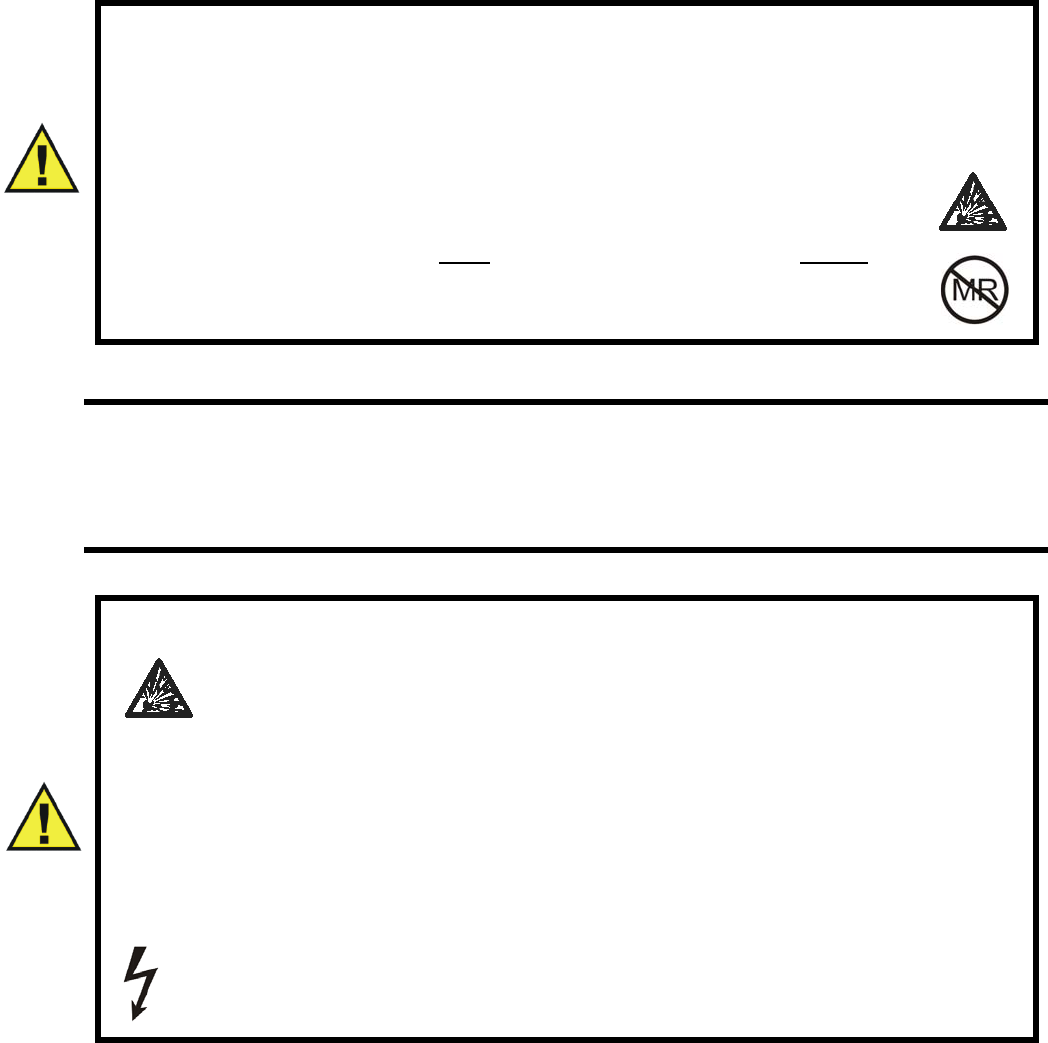
2-6
WARNING
• When charging the battery, only use the Invivo Wireless Module Battery
Charger for Precess MRI Patient Monitoring System, Part Number 9023.
• Do not attach the battery to power supply plug or directly to an automobile
cigarette lighter.
• Do not place the battery in or near fire, or in direct sunlight. Heating
the battery will damage the safety circuitry, which can cause
additional heating, rupture, or ignition of the battery.
• The battery charger is NOT MRI COMPATIBLE, and MUST be
located outside the Magnet Room.
CAUTION
• To reduce the risk of injury, charge only rechargeable batteries Part Number 9065.
Other types of batteries will burst causing personal injury and damage.
• To prevent electrical shock when cleaning the unit, always unplug the unit from
AC power.
WARNING
Do not continue charging the battery if it does not recharge within the
specified charging time. Doing so will cause the battery to become
hot, explode, or ignite.
The temperature range over which the battery can be charged is 0°C to
45°C. Charging the battery at temperatures outside this range will cause severe
damage to the battery or reduce battery life expectancy.
If the power module or power cord is damaged, it must be replaced by an
authorized Invivo part.
For protection against fire hazard, there are no repairable parts. If servicing is
needed, contact Invivo or an authorized Invivo Service Agent.
To prevent against electrical shock, refer all servicing to an authorized
Invivo Service Agent.
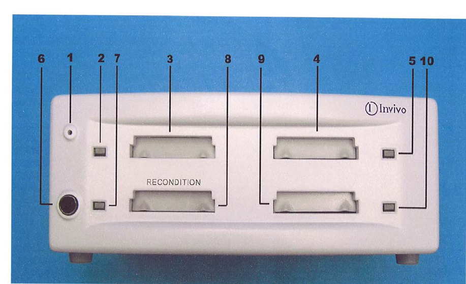
2-7
c. Wireless Module Battery Charger Description. The following is a description of
Precess Part Number 9023 Battery Charger, indicators, and connections
(Figure 2-6).
Figure 2-6. 3.7V Battery Charger, Part Number 9023
(Item 1) - Battery Charger Power Indicator. This green LED indicates that
power is being supplied to the battery charger from either Part Number
9063 Power Module or Model 9023 battery charger.
(Item 2) - Battery Bay 1 Indicator. This LED indicates the charging status of the
battery inserted in Battery Bay 1.
(Item 3) - Battery Bay 1. Battery Bay 1 provides for the insertion of Part Number
9065 Lithium Battery for recharging purposes.
(Item 4) - Battery Bay 2. Battery Bay 2 provides for the insertion of Part Number
9065 Lithium Battery for recharging purposes.
(Item 5) - Battery Bay 2 Indicator. This LED indicates the charging status of the
battery inserted in Battery Bay 2.
(Item 6) - Reconditioning Button. The Reconditioning Button is provided to
allow the user to accept reconditioning of Part Number 9065 Lithium Battery
when there is a flashing blue LED indicator. Reconditioning will result in a longer
down time for the battery being reconditioned.
(Item 7) - Battery Bay 3 Indicator. This LED indicates the charging status of the
battery inserted in Battery Bay 3.
(Item 8) - Battery Bay 3. Battery Bay 3 provides for the insertion of Part Number
9065 Lithium Battery for recharging and reconditioning purposes.
(Item 9) - Battery Bay 4. Battery Bay 4 provides for the insertion of Part Number
9065 Lithium Battery for recharging purposes.
(Item 10) - Battery Bay 4 Indicator. This LED indicates the charging status of the
battery inserted in Battery Bay 4.
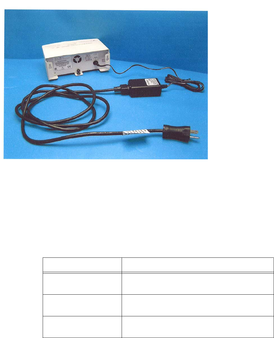
2-8
d. Wireless Module Battery Charger Power Connection Procedure. The Wireless
Module Battery Charger uses 5 Vdc from Part Number 9063 Power Module.
Connection is made by plugging Part Number 9063 Power Module into an AC
outlet, then connecting the output power cable into the power connection on the
back of the charger unit (Figure 2-7).
Figure 2-7. Wireless Module Battery Charger Power Connection
e. Charging Cycle Description. The Wireless Module Battery Charger system
consists of four separate charger bays that are individually fused. If there is a
failure in any of the four charger bays that causes the internal fuse to blow, the
other bays will still operate (provided there has not been such a failure in them as
well). When a battery is inserted into the charger, the associated LED will light to
indicate the status of the battery. This charge indicator will change colors as the
status of the battery changes during the charging cycle. The battery indicator will
remain lit with a solid green LED when the battery is charged to within 5% of the
full value (4.2 Vdc). See Table 2-1 for the list of LED indications.
Table 2-1. LED Indications
LED Condition LED Indication
YELLOW FLASHING Low battery charging.
Battery capacity < 70%.
GREEN FLASHING Medium battery charging.
Battery capacity > 70%.
GREEN SOLID Charge complete.
Battery capacity > 95%.
Input 100-240 Vac
Output 5 Vdc

2-9
If the indicator is showing a RED LED, remove power from the battery charger to
allow it to reset and then re-apply power and use as normal. If after resetting the
battery charger the LED again shows RED, then there is a fault in the battery or
battery bay.
* If the indicator is showing a SOLID RED LED, this is indicating a fault in the
battery. If the battery has been removed and re-inserted into the same battery bay
or another bay, and during the charge cycle again shows SOLID RED, then the
battery needs to be replaced.
** If the indicator shows a FLASHING RED LED, this is indicating that there will
be a fault in that battery bay. Remove and re-insert the battery into the battery bay.
If during the charge cycle the indicator again shows FLASHING RED, then that
battery bay is no longer usable. Try inserting the battery into another bay. If the
indicator on the alternate bay shows that it is charging normally, then when the
LED is SOLID GREEN, the battery is completely charged and usable.
*** During the first 15 seconds of inserting the battery, if the indicator shows a
BLUE FLASHING LED, the chip in the battery is requesting that the battery be
reconditioned. If this is ignored, the battery will go through its normal recharge
cycle, but the Precess MRI Patient Monitoring System will not give the correct
indication of battery life. To recondition the battery, it must be moved to Battery
Bay 3 and the RECONDITIONING button pressed. Reconditioning takes 8 hours.
f. Wireless Module Battery Charging Procedure. Perform the following to charge
Part Number 9065 Lithium Battery.
Step 1. Insert Part Number 9065 Lithium Battery into an open battery bay
until it is firmly seated.
Step 2. Check the status indicator for that battery bay. If it is flashing blue
and you want to recondition the battery, move it to Battery Bay 3. If it is
available, then push the Reconditioning Button. Otherwise, the charger will
go into its normal charge cycle after 15 seconds.
Step 3. When the indicator shows solid green, the battery is fully charge
and ready for use.
RED FLASHING ** Charger malfunction.
Charge control has been lost.
Remove battery.
RED SOLID * Battery fault.
A charging parameter of current, voltage,
temperature, or time has exceeded limits.
BLUE FLASHING *** Battery capacity reconditioning requested.
The battery Smart Chip requests a reassessment of
battery capacity.
BLUE SOLID Reconditioning in progress.
NO Color No battery detected.
Table 2-1. LED Indications
LED Condition LED Indication

2-10
2.5 Battery Operation. The bottom area of the DCU display contains the System Status
Area. This area is dedicated to displaying battery and wireless communication status. Refer to
Section 1.6.2, page 1-10, for a full explanation of the Battery Status Display. Maximum operation
time of the battery (Invivo Part Number 9093 or 9064) is approximately eight (8) hours when
NIBP, ECG, SpO2 parameters are running on 5-minute intervals, and anesthetic agents and EtCO2
are turned off. (Battery operation time will be reduced by up to two (2) hours by performing
certain operations like anesthetic agents, printing charts and trends, or short automatic NIBP cycle
times).
The minimum voltage value for normal operation for Invivo Part Number 9064 battery is 14.4V.
The minimum voltage value for Invivo Part Number 9065 battery is 3.5V. The minimum voltage
value for normal operation for Invivo Part Number 9093 is 14.8V.
The Precess performs an automatic switchover to internal batteries when the line power is
interrupted and batteries in the WPU and DCU are in place.
2.6 System Setup.
2.6.1 WPU and DCU.
a. Install the batteries into the WPU and DCU as described above in Section 2.3.
b. Locate a Precess AC to DC Power Supply (Invivo Part Number AS201) and attach
the AC Power Cord as shown in Figure 2-8. Connect the male end of the 25 ft. DC
Power Cable (Invivo Part Number AC517B) to the DC OUTPUT on the Power
Supply (Figure 2-9). Locate this Power Supply in the MRI Exam Room near an
approved AC outlet at a distance of at least 10 feet (3 meters) from the MRI
magnet. Plug the AC Power Cord into the AC outlet. Plug the female end of the
DC Power Cable into the Power Input on the WPU (see Figure 2-10).
c. Locate another Precess AC to DC Power Supply (Invivo Part Number AS201) and
attach the AC Power Cord. Connect the male end of the 5 ft. DC Power Cable
(Invivo Part Number AC517A) to the DC OUTPUT on the Power Supply. Locate
this Power Supply in the MRI Control Room or MRI Holding Room near an
approved AC outlet. Plug the AC Power Cord into the AC outlet. Plug the female
end of the DC Power Cable into the Power Input on the back of the DCU
(see Figure 2-11).
d. Repeat Step C for each additional DCU that will be used with the system.
e. When installing the system for the first time, all batteries mustwill be charged for
at least twelve (12) hours with the Precess system turned off in order that the
batteries are fully charged and conditioned for operation.
f. Turn on the WPU with the power switch located next to the Patient Connections
Unit (PCU).
g. Turn on the DCU with the power switch located at the front panel.
h. Verify the proper operation of each installed patient parameter. Reference Section 3
in this manual.
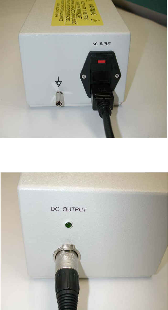
2-11
Figure 2-8. AC Power Connection To Precess AC to DC
Power Supply (Part Number AS201)
Figure 2-9. Precess DC Power Connection To Precessc AC To DC
Power Supply (Part Number AS201)
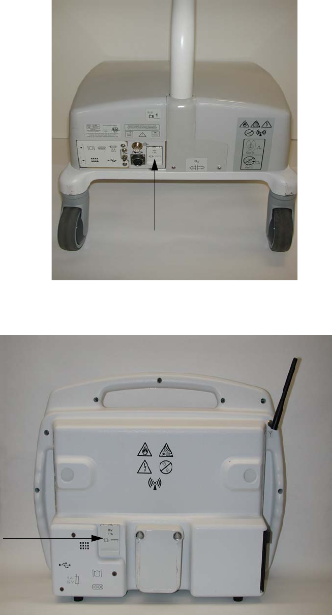
2-12
Figure 2-10. WPU Hardwire Location
Figure 2-11. DCU Power Input
WPU Power Door
DCU Power
Door

2-13
2.7 System Location. The Precess MRI Patient Monitoring System is compatible with all
MRI systems between 0.15 and 3.0 Tesla. Select a location where the system is outside the 5,000
Gauss (0.5T) Field Line (outside the 1,000 Gauss (0.1T) Field Line for a DCU with the Recorder
Option). Also, choose a location where the system will not come in contact with liquids and
where it will not be exposed to temperatures above 44°C (110°F). Maintain adequate air flow
around each system component in order that the normal operating temperature range is not
exceeded.
2.8 Before Connecting To A Patient. Perform the following steps to prepare the system for
use.
Step 1. Ensure that there is no damage to any system component.
Step 2. Ensure that all patient connections are properly connected.
Step 3. Ensure that all patient accessories being utilized (NIBP hoses, cuffs, ECG lead
wires, etc.) are listed in the Accessories section of this manual (Page xv). Visually inspect
all accessories for damage. Replace any accessories that show signs of damage or abuse.
Step 4. Report any problems to an authorized Invivo Service Representative.
Step 5. Verify that each patient parameter is functioning properly before using the system
on a patient. Never use a system that is suspected of not operating properly or out of
calibration.
CAUTION
The WPU and DCU batteries (Part Number 9064 or 9093) contain some ferrous
materials that are attracted to the MRI magnetic field. DO NOT remove the batteries
from the WPU or DCU when these units are closer than the 1,000 Gauss line
(0.1 Tesla) as the batteries will be attracted to the magnetic field, thus causing patient
or user injury.
WARNING
Ensure Part Number AS201 Power Supply remains 10 feet (3 meters) or more
from the magnet.

3-1
SECTION 3
PATIENT PARAMETERS
3.0 PATIENT PARAMETERS.
3.1 ECG Monitoring. Unless it has been turned off in the ECG Menu, the selected ECG lead
is displayed as TRACE A. TRACE B may also be selected. Most ECG functions are contained in
the ECG Menu. Additional features useful with ECG monitoring are found in three secondary
menus:
•RECORDER Menu. Used to select all recorder functions and to set the recorder
and trace speed.
•ALARMS Menu. Used to Set and/or Disable the ECG alarms. The range of
Alarm Limits for the ECG Heart Rate is 30 to 249 bpm.
•HEART RATE TREND Menu. Used to setup and print Trended information.
•PEDIATRIC ECG Menu. This menu is used to provide specific ECG filtering for
those patients with narrow QRS complexes and higher heart rates (> 120 beats per
minute) that may cause disruption of normal ECG processing. See Paragraph 4.2
for further explanation.
For further information on the secondary menus, see the corresponding paragraphs of this
document.
Although it may appear that electrocardiogram (ECG) monitoring in the Magnetic Resonance
Imaging (MRI) area is similar to that performed in other areas of the clinical environment, the
conditions found inside the MRI area are unique and require additional precautions to be followed
in order to permit the safe monitoring of the patient during MRI procedures. It is always important
to remember that the risk of radio frequency (RF) heating is ever-present when any electrical
conductor, for example ECG lead wires, are placed in the MRI system bore. By following the
Invivo operating precautions, warnings, and the guidelines below, these risks can be minimized.
3.1.1 Wireless ECG Module and ECG Patient Lead Wires. The Invivo Wireless ECG Module
(Part Number 9312, Figure 3-1) and ECG Patient Lead Wires are specially designed for use in the
MRI system bore, although the module must not be placed within the MRI procedure Field-Of-
View (FOV). Placing the Wireless ECG Module within the FOV may interrupt ECG monitoring
during the MRI procedure and cause artifact on the MRI image. The Invivo MRI ECG lead wires
(Part Numbers 9224, 9223, and 9222) are constructed of special material to reduce the amount of
radio frequency (RF) energy that can flow through these wires. The ECG Lead Wires must always
be kept in a straight line and must not touch the MRI system bore. Any loop (circular, “U” shaped,
“S” shaped) in the lead wires and/or contact with the MRI system bore will cause heating of the
lead wires or the patient electrodes. Never use any ECG lead wires other than the Invivo MRI
ECG lead wires (Invivo Part Numbers 9224, 9223, and 9222).The misuse or the use of lead
wires other than the Invivo MRI ECG Lead Wires will cause excessive RF current to flow through
the lead wires, thus causing the potential for heating at the ECG lead wires and the electrodes.
Heating of the ECG lead wires and electrodes can lead to minor severe burns at the patient’s skin.
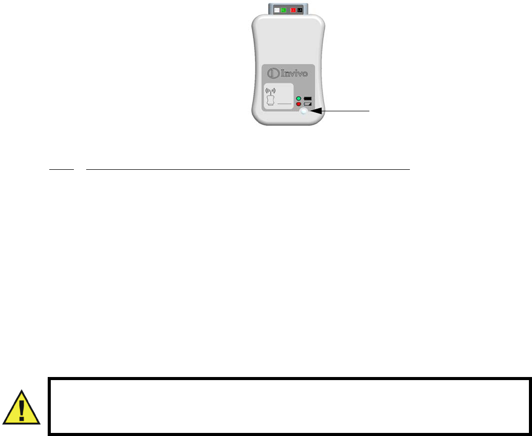
3-2
The Wireless ECG Module, ECG Patient Lead Wires, and Quadtrode ECG Electrodes are
compatible with MRI systems up to 3.0 Tesla with Specific Absorption Ratios (SAR) up to
4.0 W/kg. Use at SAR levels above 4.0 W/kg increases the heating risk at ECG patient lead wires
and electrodes.
Figure 3-1. WECG Module with Power/Communication LED
3.1.2
ECG Electrode - Use only Invivo Quadtrode MRI ECG Electrodes. These ECG electrodes
are design specifically for use in the MRI environment. Use of the Invivo Quadtrode electrodes will
minimize the possible risk of ECG electrode and cable heating during MRI procedures and reduce the
amount of MRI generated artifact on the ECG waveform. Three different Quadtrode MRI ECG
Electrodes are available for differing applications:
•Invivo Quadtrode MRI ECG Electrodes (Part Number 9303A) are designed
for use during general MRI procedures on adult and pediatric patients above 10 kg
(22 lbs.).
•Invivo Quadtrode CV MRI ECG Electrodes (Part Number 9371A) are
designed for use during Cardiovascular (CV) MRI procedures.
•Invivo Neonatal Quadtrode MRI ECG Electrodes (Part Number 9372) are
designed for use during general MRI procedures on neonatal or infant patients
below 10 kg (22 lbs.).
Follow the Patient Preparation and Quadtrode Placement instructions provided on each
Quadtrode foil package.
•Electrode Site Selection. Monitoring ECG in the MRI environment is particularly
challenging because of the inherent distortion of the ECG waveform by the MRI
magnetic field. These blood flow induced distortions of the ECG are due to the
large amount of blood moving through the vessels of the heart (aorta). Blood
(a very good electrical conductor) moving through the large magnetic field of the
MRI produces an electrical potential that adds to the ECG signal. This induced
electrical potential is seen primarily as an augmentation of the ECG T-wave
amplitude, although other non-specific waveform changes are also apparent on the
ECG. Since an elevated T-wave or ST segment will be associated with true
physiologic disorders, the statis magnetic field-induced ECG-distortions will be
problematic. For this reason, a baseline recording of the ECG prior to placing the
patient inside the MRI magnetic bore will be necessary. The proper placement of
the ECG electrodes in the MRI is critical to reducing the blood flow induced
distortion of the ECG waveform. With proper strategic placement of the ECG
electrodes and minimization of the electrode lead wire length, this blood flow
induced distortion can be kept to a minimum. Following the instructions provided
WARNING
Before applying a Quadtrode® MRI ECG Electrode to a patient, always verify that
the expiration date on the back of the Quadtrode® foil packaging is valid.
Power/Communication LED

3-3
on the specific Quadtrode foil packaging will minimize the blood flow induced
distortion on the ECG signal. Additional artifacts caused by the static, gradient,
and RF electromagnetic fields can severely distort the ECG, making observation of
the morphologic changes and detection of arrhythmia quite difficult. Monitoring a
different ECG lead (I, II, III, AVL, AVR, AVF) will minimize some of these
artifacts.
•Electrode Site Preparation. If necessary, shave the selected site(s) to remove any
hair from the electrode site(s). Apply ECG Skin Prep Gel (Invivo Part Number
9009) to a gauze pad. Briskly rub the selected site(s) with this gauze pad. Remove
excess gel with a clean gauze. The ECG Skin Prep gel contains light abrasive
pumice and saline that clean and enhance the conductive properties of the patients
skin, thus enhancing ECG performance. Isopropyl/rubbing alcohol must not be
used to prep the skin as it breaks down the conductive properties of the skin, thus
degrading ECG performance. Follow the Patient Preparation and Quadtrode
Placement instructions provided on each Quadtrode foil package.
•Checking Electrode Contact Quality. Electrode preparation has a direct bearing
on ECG performance. The result of poor electrode preparation will be poor ECG
monitoring performance. A standard means to evaluate electrode contact is to
measure the electrical conductance (impedance) between electrodes to verify that
the impedance is below 8,000 ohms. Once the electrode site has been prepared and
the Quadtrode placed, the optional Electrode Impedance Meter (Invivo Part
Number 9392) can be attached to the LA, RA, and LL Quadtrode connections.
Refer to the instructions on the Electrode Impedance Meter. Since only three lead
wires can be connected simultaneously, the user will need to check the fourth
electrode (RL) with the LL (Red) lead wire. If electrode contact is poor (greater
than 8,000 ohms), remove and discard the electrode, and repeat the site preparation
according to the instructions above. Never reuse a removed electrode since its
adhesive will not securely fasten the Quadtrode electrode to the patient’s skin. Re-
check the impedance electrodes and verify that acceptable impedance is achieved.
•Other Electrical Conductors Inside The MRI System Bore. No other electrical
conductor (e.g. wires, leads, probes, etc.) are tomust be placed inside the MRI
system bore at the same time as the Invivo MRI ECG lead wires (Part Numbers
9224, 9223, and 9222) as the risk of lead wire and electrode heating increases. It is
always important to identify if the patient has any metallic wires, conductors,
implants, stents, etc. within his/her body as these items will interact, thus
increasing the risk of lead wire and electrode heating.
Table 3-1. WECG Power/Communication LED
LED Indication Power Source Communication
Status
SOLID YELLOW On battery power Good communications
with a WPU
SOLID RED Low battery condition Good communications
with a WPU
BLINKING YELLOW On battery power No communications
BLINKING RED Low battery condition No communications
NO LIGHT Dead battery N/A
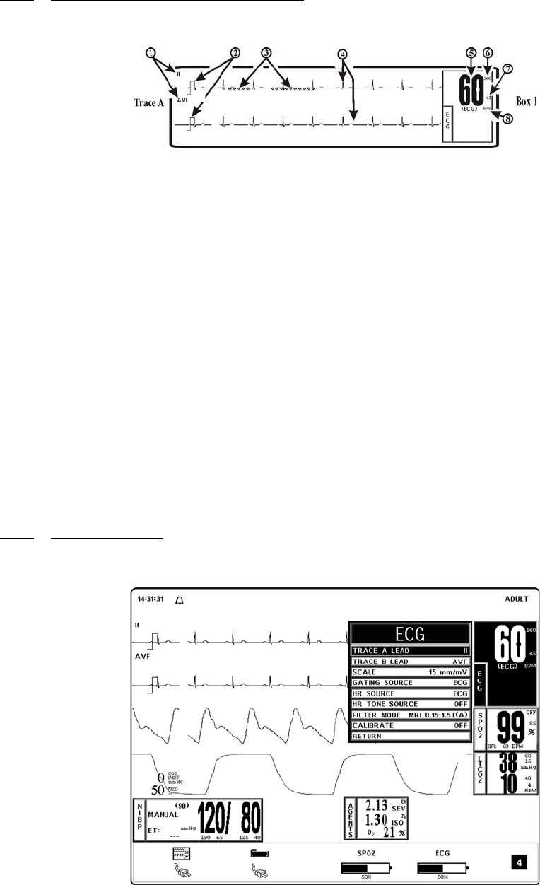
3-4
3.1.3 Associated Waveforms and Displays. (See Figure 3-2.) ECG information is displayed as
a waveform in the Trace A location and as numeric data in the Box 1 and 2 locations. The
following is a description of the items contained within the ECG Display.
Figure 3-2. ECG Trace and Numerical Displays
a. ECG Lead. (Item 1) Displays the ECG Lead selected for use.
b. Scale Indicator. (Item 2) This indicator is provided for a reference and represents
a 1 millivolt signal amplitude.
c. Message Areas. (Item 3) These areas display software messages: The area on the
left displays ECG specific messages while the larger area on the right displays all
types of system messages.
d. Waveform Traces. (Item 4) Displays the ECG waveform of the patient.
e. Heart Rate Numeric. (Item 5) Displays the current Heart Rate indication for the
patient.
f. Alarm Limit High. (Item 6) Displays the value set for the High Limit of the ECG
Heart Rate Alarm. This item is under operator control and may be turned on or off
as required.
g. Alarm Limit Low. (Item 7) Displays the value set for the Low Limit of the ECG
Heart Rate Alarm. This item is under operator control and may be turned on or off
as required.
h. Heart Rate Source. (Item 8) Displays the source selected for the Heart Rate.
3.1.4 The ECG Menu. (See Figure 3-3.) Selecting the ECG Menu-Select Icon brings up the
ECG Menu. This menu has a time-out feature. If no action is taken for approximately 60 seconds,
the monitor will automatically return to the Normal Screen.
Figure 3-3. The ECG Menu
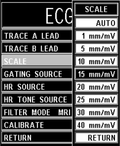
3-5
The following selections are available in the ECG Menu:
a. TRACE A LEAD. Selecting this menu option allows the selection of the
ECG 1 Lead. The options are I, II (default), III AVL, AVR, AVF and OFF.
b. TRACE B LEAD. Selecting this menu option allows the selection of the
ECG 2 Lead. The options are I, II, III AVL, AVR, AVF, and OFF.
c. SCALE. Selecting this menu option allows the selection of the scale for the
ECG waveform(s). The options are AUTO, 1, 5, 10 (default), 15, 20, 25, 30, and
40 mm/mv (See Figure 3-4). The selected scale appears on the right hand side of
this menu option. If AUTO is selected, a scale is picked that would make the
current waveform(s) fill the ECG viewing area. This scale will be in effect until
another scale is selected (AUTO or any other selection). A Scale Indicator
associated with the Trace is displayed on the left side of the screen, and denotes a
1 millivolt signal amplitude.
Figure 3-4. The ECG SCALE Sub-Menu
(1) If the Scale of the ECG trace is so large that the top or bottom of the ECG
waveform is distorted or flattened, the “OVERSCALE” message flashes in
the ECG waveform area. This message will override other ECG error
messages. Use the SCALE Menu Option (in the ECG Menu) to resize the
waveform until the “OVERSCALE” message stops flashing. If this
continues, the Auto Scale Option must be selected to prevent further
waveform distortion.
(2) The ECG waveform may be frozen for closer examination by pressing the
FREEZE Control Key. When the waveform is frozen, it is displayed below
Trace A with a “Blue Box” around it. While FREEZE is Enabled, changes
to the Parameter Selections are not allowed; if the operator tries to access
the Parameter Selection Menu, a WARNING Box appears to alert the
operator that the selected menu may not be accessed.
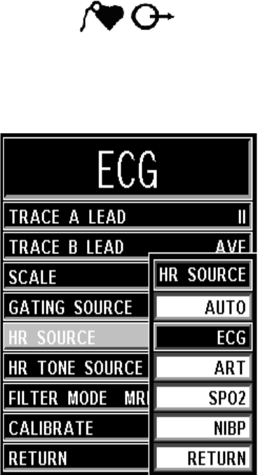
3-6
d. GATING SOURCE. Selecting this menu option allows the selection of the
Source to be used for MRI Gating. The options are ECG and PULSE. The MRI
Gating connector is located at the back of the WPU. This connector is denoted by
the symbol below. An optional gating interface cable is needed to connect the
Precess system to various manufacturers’ MRI systems.
e. HR SOURCE. Selecting this menu option allows the selection of the Source to be
used for the Heart Rate display in TRACE A area. The options are AUTO, ECG
(default), ART, SPO2 and NIBP (See Figure 3-5).
Figure 3-5. The ECG HR SOURCE Sub-Menu
(1) The Heart Rate is displayed in the ECG parameter box. It is annotated with
its Source (e.g., “60 ECG” indicates a Heart Rate of 60, derived from
ECG).
(2) If AUTO is chosen, the Heart Rate is selected automatically from the
highest priority active input. When set to AUTO the Precess MRI Patient
Monitoring System searches for another source for rate only when LEAD
FAIL occurs or the ECG parameter is turned OFF. The priority, from
highest to lowest, is ECG, SpO2, and NIBP.
(3) The Precess MRI Patient Monitoring System examines the highest priority
active input. If not found, it will go to the next highest priority parameter. If
none of the parameters are presenting a Heart Rate and NIBP is shut OFF,
then “NONE” is displayed on the screen in the Heart Rate position.
(4) HR Tone Source is only set for ECG or SpO2.
(5) This menu option is identical to, and interactive with, the similarly named
menu options under SPO2 and NIBP.
f. HR TONE SOURCE. Selecting this menu option selects the Source to be used for
the Heart Rate Tone. The options are QRS, SPO2 and OFF (default). When this
Parameter is set to OFF, the Heart symbol will not be displayed.
3-7
(1) When the SpO2 Parameter provides the Heart Rate Tone, the Tone is
modulated by the SpO2 value.
(2) If the Heart Rate Tone Source is turned OFF, the Heart Symbol is removed
from the display.
(3) This menu option is identical to, and interactive with, the HR Tone Source
Option in the Sound Adjust Menu.
g. FILTER MODE. Selecting this menu option allows the user to choose the ECG
Filter that provides the best ECG performance during various types of MRI
sequences. The following Filter Modes are available:
(1) Monitor. This Filter Mode provides ECG waveform filtering
characteristics that meet the specification of the Association for the
Advancement of Medical Instrumentation (AAMI). Note that this Filter
will not provide optimum performance during active MRI sequences.
(2) MRI 0.15 - 1.5T (A). This Filter Mode provides optimum performance on
0.15 to 1.5 Tesla MRI systems during non-Cardiovascular (CV) MRI
sequences. This MRI Filter utilizes an adaptive filter scheme for removal
of gradient artifact generated by MRI systems.
(3) MRI 0.15 - 1.5T (B). This Filter Mode provides optimum performance on
0.15 to 1.5 Tesla MRI systems during Echo Train MRI sequences. This
MRI Filter utilizes an adaptive filter scheme for removal of gradient
artifact generated by MRI systems.
(4) Cardiac 1.5 - 3.0T. This Filter Mode provides the optimum ECG
performance during Cardiovascular (CV) MRI procedures that involve
steady state free precession imaging with balanced gradient (True-FISP,
FIESTA, or Balanced FFE) sequences on 1.5 and 3.0 Tesla MRI systems.
This MRI Filter utilizes an adaptive filter scheme for removal of gradient
artifact generated by MRI systems.
(5) 3.0T. This Filter Mode provides optimum performance on 3.0 Tesla MRI
systems during non-Cardiovascular (CV) MRI sequences. This MRI Filter
utilizes an adaptive filter scheme for removal of gradient artifact generated
by MRI systems.
Due to the variety of MRI sequence characteristics, the ECG filter mode
recommendations above my not provide optimum performance in all cases.
Therefore, in situations where the recommended filter mode does not provide
optimum ECG performance, the selection of other ECG filter modes nay impoprve
ECG performance.
ECG performance can be affected by ECG electrode placement as well as MRI
procedure, image slice angle, and image slice thickness. In situations where ECG
performance is not optimal, select the ECG lead (I, II, III, AVL, AVR, or AVF) that
provides optimum ECG performance
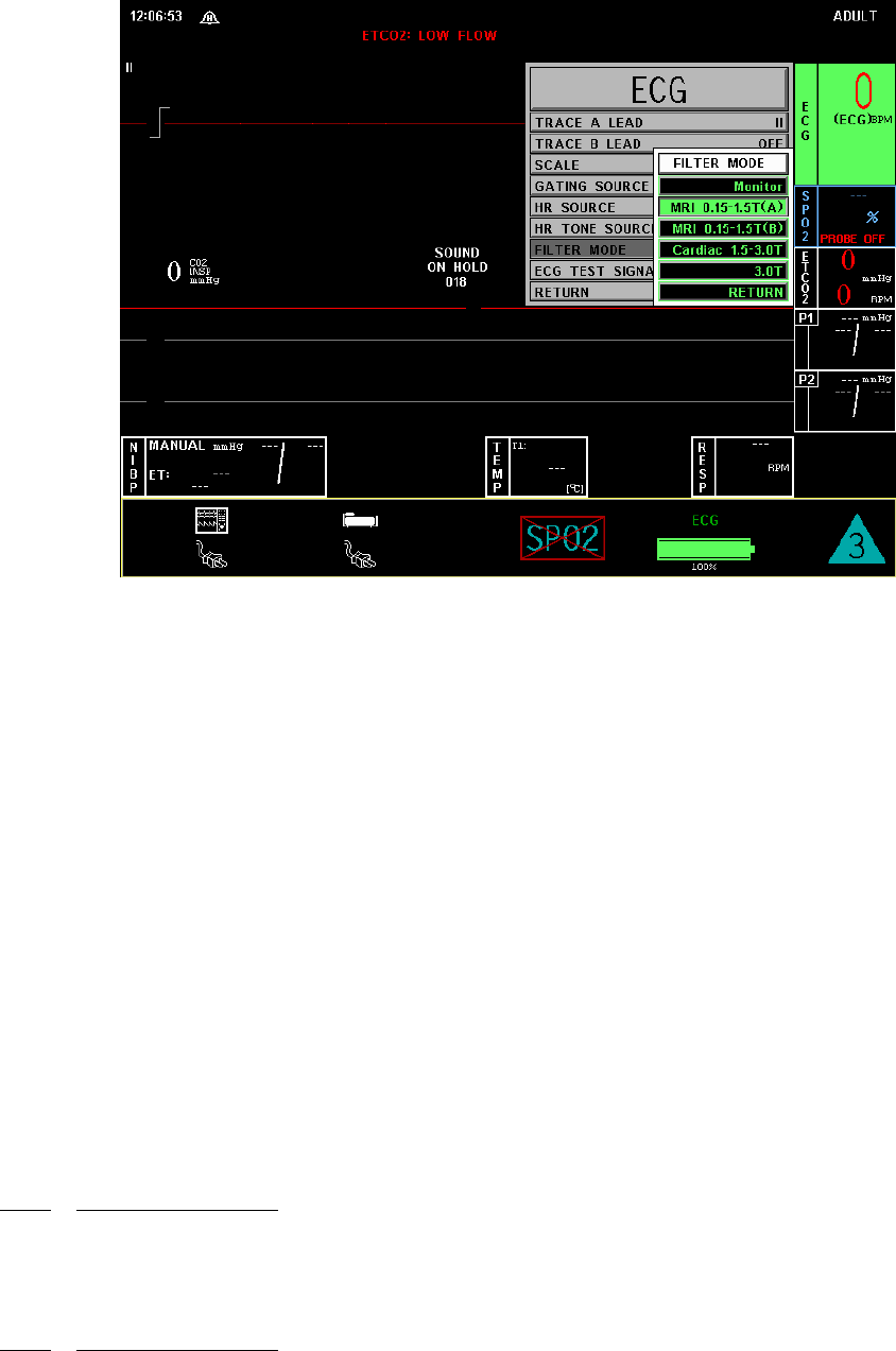
3-8
Figure 3-6. Filter Mode Menu
h. ECG TEST SIGNAL. Selecting this menu option opens the ECG Test Signal
Menu. This menu option is identical to and interactive with the Calibrate Option in
the Recorder Menu. The following options are available in the ECG Test Signal
Menu:
(1) OFF. Selecting this menu option turns the CALIBRATION feature OFF.
(2) RECORDER. Selecting this menu option sends a 1mV pulse calibration
waveform to the ECG Vital Sign and will also be the ECG waveform
printed by the Recorder if so configured. The message “ECG TEST
SIGNAL” is displayed over the ECG waveform on the screen.
(3) ECG. Selecting this menu option sends a 1mV peak to peak calibration
signal to the ECG vital sign and will also be the ECG waveform printed by
the Recorder if so configured. The message “ECG TEST SIGNAL” is
displayed over the ECG waveform on the screen. It is important to note that
this is a hardware generated calibration waveform and originates as a
square wave by the WECG module.
(4) RETURN. Selecting this menu option closes the Calibrate Menu.
i. RETURN. Selecting this menu option will return the DCU Display to the Normal
Screen.
3.1.5 ECG Alarm Limits. Alarm Limits may be set two ways. To set the Alarm Limits for every
available parameter, from the Normal Screen (with no icons highlighted), press the ALARMS
SCREEN Menu-Select Key. To set the Alarm Limits for ECG Heart Rate only, highlight the ECG
Icon and press the ALARMS SCREEN Menu-Select Key to access the individual parameter
Alarm Limits Box. The range of Alarm Limits for the ECG Heart Rate is 30 to 249 bpm.
3.1.6 ECG Trended Data. For complete information on the trending of patient ECG data, see
Section 5, Recording and Trending.

3-9
3.1.7 ECG Messages. The following is a list of messages that may be displayed during ECG
monitoring:
3.2 Non-Invasive Blood Pressure (NIBP) Monitoring The NIBP feature measures and
displays systolic, diastolic and mean arterial pressures, and pulse rate. LOW and HIGH Alarm
Limits are available for all three pressures. When the Precess MRI Patient Monitoring System is
configured to obtain the patient's heart rate from the NIBP, the Heart Rate Alarm is also
applicable to this parameter. The system may be set to take NIBP readings at automatic intervals
from 1 to 240 minutes (there is a 20 second pause between readings to allow for peripheral
perfusion), or the operator can manually initiate a reading at any time.
LEAD FAIL LEAD FAIL is displayed when a faulty or disconnected ECG Lead is
detected by the system.
NOTE
If the RL lead and an additional lead become disconnected, the system will not detect
a lead failure.
OVERSCALE OVERSCALE is displayed if the scale of the ECG Trace is so large
that the tops of the ECG waveforms are being “clipped” (the tops and
bottoms cut off). This message suppresses all other ECG Error
Messages and the Alarm Tone will not sound.To reduce the scale,
and remove the OVERSCALE message, access the SCALE menu
option in the ECG Menu.
NOTE
The NIBP measurement range for Adult and Neonates is provided in Appendix A.
An “out-of-range-signal” for NIBP is a measured pressure that is not within this range.
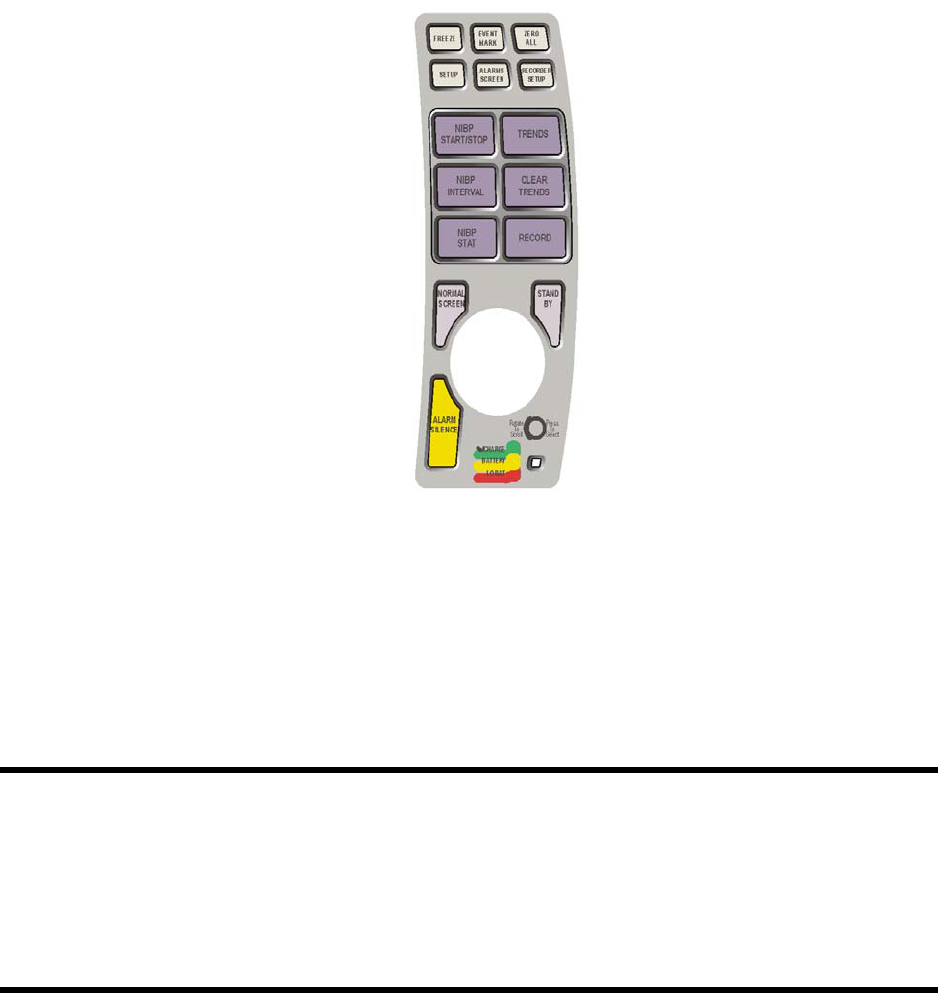
3-10
When a successful reading is taken, the elapsed time display indicates the beginning of this cycle.
The time until next measurement indicates when the next automatic measurement will be made.
A manual reading does not restart this cycle time. The NIBP INTERVAL Key may be used to
adjust the cycle time. The NIBP START/STOP Key may be used to manually Start/Stop a
measurement. The NIBP STAT Key allows the start of STAT Mode (which makes five (5) NIBP
determinations in rapid succession).
Figure 3-7. 3160 Keypad
•Error. If an error is detected, the Alarm Tone will sound, and an error message
will appear on the display.
•Artifact. Non-Invasive blood pressure monitoring is sensitive to patient motion
artifact. Such artifact can cause readings to be slow or even an incorrect pressure
reading.
•Standard Routine. Visual checks of the patient, other vital signs and checking the
limb to which the cuff is attached must be standard routines with NIBP use.
CAUTION
Substitution of a component different from that supplied might result in measurement
error.
If a measurement is in progress and communication is lost between the DCU and
WPU, the measurement is aborted.
NIBP accuracy has not been verified in the presence of some common arrhythmias
such as atrial or ventricular premature beats or atrial fibrillation.
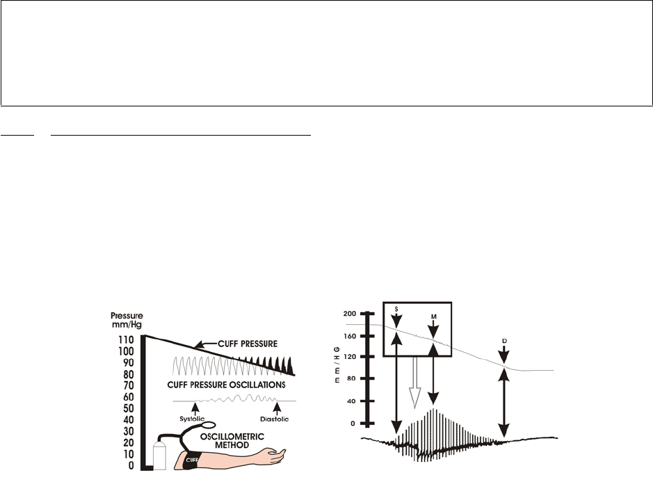
3-11
Most NIBP functions are contained in the primary NIBP Menu. However, additional features
useful with NIBP monitoring can be found in the three secondary menus associated with this
parameter:
•RECORDER Menu. Used to select Recorder functions and to Set the Recorder
Trace Speed.
•ALARMS Menu. Used to Set and/or Disable the NIBP Alarms. The range of
Alarm Limits for the NIBP is 5 to 249 mmHg.
•NIBP TREND Menu. Used to Setup and Print Trended information.
3.2.1 Theory of Oscillometric Measurement. This system obtains blood pressure measurements
based on the Oscillometric principle. Oscillometric Monitors use an inflatable occlusive cuff
which can also be used in the manual auscultatory technique; however, rather than monitoring
Korotkoff sounds, Oscillometric Monitors detect and measure oscillations induced in the cuff by
the movement of the arterial wall. In basic terms, oscillometric monitors utilize a pressure
transducer which is connected to the cuff via a hose. The transducer transforms the oscillations
induced into the cuff pressure into electrical currents. Under control of a microprocessor and
software algorithms, the electrical current can then be measured and correlated with the cuff
pressure to determine arterial blood pressure. The following describes the process of
Oscillometric Measurement:
Figure 3-8. Oscillometric Measurement Method
a. As the occlusive cuff is inflated to a suprasystolic pressure, the artery is occluded
so that no blood passes through. At this point, even though no blood flows under
the cuff, there are small pulsations induced into the cuff pressure by the partially-
occluded proximal portion of the artery lying under the cuff (See Figure 3-8).
b. As cuff pressure is reduced to just below the systolic pressure, the force of the
height of the systolic pressure wave forces the occluded artery open, blood spurts
through the artery and the amplitude of the oscillations increase sharply. This is the
systolic pressure.
NOTE
Blood pressure measurements determined with this device are equivalent to those
obtained by a trained observer using the cuff/stethoscope auscultatory method, within
the limits prescribed by the American National Standard, Manual, electronic, or
automated sphygmomanometers.

3-12
c. With further reduction in cuff pressure the artery opens for a longer time during
each cardiac cycle, which causes increasingly larger oscillations in the cuff
pressure until they reach a point of maximum oscillation amplitude. This point of
maximum oscillations has been well demonstrated to be Mean Arterial Pressure.
d. With continued cuff pressure reduction, the underlying artery is open throughout
the cardiac cycle, and the arterial wall movement is less. The cuff pressure
oscillations begin to decrease in amplitude until they become uniform. The point at
which the amplitudes become uniform is diastolic pressure.
3.2.2 NIBP Patient and Cuff Preparation. The patient must remain calm and motionless while
the system is being used. If the patient is overactive, prolonged or inaccurate readings will result.
Perform the following to prepare the patient and cuff for monitoring
a. Cuff Selection. The cuff is selected and positioned as it would be for an
auscultatory blood pressure determination, and the current guidelines of the
American Heart Association must be followed. The bladder width of the cuff must
be 40% of the circumference of the limb. For a correct fit on adult and pediatric
cuffs, the Index line on the end of the cuff must fall between the two Range lines
printed on the inside of the cuff. For correct fit on neonatal cuffs, choose the size
with the stated circumference range that fits the circumference of the limb of the
neonate.
b. Cuff Positioning. The cuff must be wrapped firmly (not snug) around the arm or
leg of the patient. If the cuff is not at heart or leg level, add 1.8 mmHg to the
displayed readings for each inch (2.54 cm) that the center of the cuff is located
above the patient's heart level; subtract 1.8 mmHg from the displayed readings for
each inch that the cuff is located below the patient's heart level.
c. Cuff Connections. Select the proper hose (twin-lumen for adults, single-lumen for
neonates), and attach hose to cuff. Route the hose from the cuff to the PCU so it
does not kink, tangle or limit access to the patient.
3.2.3 Associated NIBP Displays. When NIBP is enabled, it is displayed in a box at the lower
left of the Normal Screen. The box is a specialized display panel that includes the information
concerning the NIBP status in one of two user selectable formats. The two available formats are
Systolic/Diastolic and Mean Only (See Figure 3-9); the user selects the format using the Format
Option in the NIBP Menu (See Section 3.2.5). The two available displays are described below:
NOTE
The point of maximum oscillations is coincident with mean arterial pressure regardless
of arterial elasticity so long as the ratio of air volume in the cuff to the volume of the
artery under compression does not greatly exceed ten (10) to one (1). For this reason it
is advisable to keep the cuff air volume to a minimum by using the smallest cuff size
possible for each patient.
WARNING
Do not attach the cuff to a limb being used for infusion. Cuff inflation can block
the infusion causing possible harm to patient.
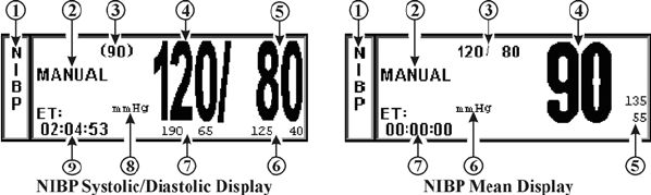
3-13
Figure 3-9. The NIBP Display
a. The NIBP Systolic/Diastolic Display. The items contained in this user selectable
display are described below:
(1) Icon Label. (Item 1) This label identifies the Parameter whose numeric
data is being displayed within the Icon Box. Box 11 (in the lower left of the
Bottom Numeric Display) is dedicated to the display of NIBP information.
(2) Manual. (Item 2) While in the Automatic Mode, “NEXT” is shown and
the time until the next NIBP determination is displayed here; in the Manual
Mode, the word “MANUAL” is displayed here.
(3) Mean Numeric. (Item 3) A numeric indication of the patient's Mean
pressure reading.
(4) Systolic Numeric. (Item 4) A numeric indication of the patients NIBP
Systolic reading.
(5) Diastolic Numeric. (Item 5) A numeric indication of the patients NIBP
Diastolic reading.
(6) Diastolic Alarm Limits. (Item 6) A numeric indication of the settings of
the High (to the left in the example) and Low (right in the example)
Diastolic Alarm Limits.
(7) Systolic Alarm Limits. (Item 7) A numeric indication of the settings of
the High (to the left in the example) and Low (right in the example)
Systolic Alarm Limits.
(8) Unit of Measurement. (Item 8) Displays the Unit of Measurement being
used for presentation of the numeric data. This item may be toggled
between mmHg and kPa using the System Configuration Menu
(See Section 4.0 for further information).
(9) ET. (Item 9) The Elapsed Time (ET) since the last NIBP determination is
displayed here. During an NIBP determination, this message changes to
display the cuff pressure.
b. The NIBP Mean Display. The items contained in this user selectable display are
described below:
(1) Icon Label. (Item 1) This label identifies the parameter whose numeric
data is being displayed within the Icon Box. Box 11 (in the lower left of the
Bottom Numeric Display) is dedicated to the display of NIBP information.
(2) Manual. (Item 2) While in the Automatic Mode, “NEXT” is shown and
the time until the next NIBP determination is displayed here; in the Manual
Mode, the word “MANUAL” is displayed here.
(3) Systolic/Diastolic Numeric. (Item 3) A numeric indication of the patient's
Systolic/Diastolic pressure reading.
(4) Mean Numeric. (Item 4) A numeric indication of the patients NIBP Mean
reading.
(5) Mean Alarm Limits. (Item 5) A numeric indication of the settings of the
High (on top in the example) and Low (bottom in the example) Mean
Alarm Limits.
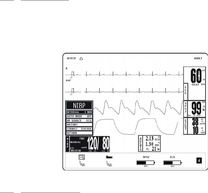
3-14
(6) Unit of Measurement. (Item 6) Displays the Unit of Measurement being
used for presentation of the numeric data. This item may be toggled
between mmHg and kPa using the System Configuration Menu
(See Section 4 for further information).
(7) ET. (Item 7) The Elapsed Time (ET) since the last NIBP determination is
displayed here. During an NIBP determination, this message changes to
display the cuff pressure.
3.2.4 The NIBP Menu. Selecting the NIBP Menu-Select Icon will bring up the NIBP Menu
(Figure 3-10). This menu provides the operator with the ability to switch the Automatic Mode
ON and OFF, set the Automatic Reading Interval, set the Heart Rate Source and bring up a
Tabular Chart containing a History of the NIBP and SpO2 determinations. This menu has a
time-out feature. If no action is taken for approximately 60 seconds, the display will
automatically return to the Normal Screen.
Figure 3-10. The NIBP Menu
3.2.5 NIBP Menu Options. The following is a description of the operation of the NIBP Menu
options:
a. INTERVAL. Selecting this menu option allows the operator to change the
Automatic Measurement Time Interval setting (Figure 3-11). The options are 1, 2,
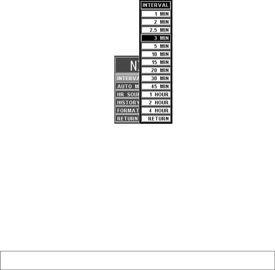
3-15
2.5, 3 (default), 5, 10, 15, 20, 30 or 45 minutes, and 1, 2 or 4 hours. The Interval
Menu can also be accessed by pressing the NIBP INTERVAL Key.
Figure 3-11. The NIBP Interval Menu
(1) As the Rotary Knob turns clockwise, the interval selection will increase.
After reaching “RETURN,” the interval selection will “roll over” to
“1 MIN” and continue to increase.
(2) As the Rotary Knob turns counter-clockwise, the interval selection will
decrease. After reaching “1 MIN,” the interval selection will “roll over” to
“RETURN” and continue to decrease.
b. AUTO MODE. Selecting this menu option allows the operator to switch the NIBP
Automatic Mode between ON and OFF (default). When switched from OFF to
ON, the operator must manually initiate the first reading (by pressing the NIBP
START/STOP Control Key); subsequent readings are taken automatically at the
operator selected interval. When in Manual Mode, readings may only be initiated
from the NIBP START/STOP or NIBP STAT Control Keys. A reading cycle may
be stopped at any time if the NIBP START/STOP Control Key or STANDBY
Control Key is pressed while it is in progress.
c. HR SOURCE. Selecting this menu option allows the selection of the source to be
used for the Heart Rate display in the ECG area. The options are AUTO, ECG
(default), ART (arterial pressure), SPO2 and NIBP.
This menu option is identical to, and interactive with, similarly named menu
options under ECG and SPO2.
d. HISTORY. Selecting this menu option brings up the History Menu (See Figure 3-12),
and displays the last 48 NIBP readings together with the heart rate, SpO2, CO2 and
respiration values at the time in a tabular form (6 readings per page). The tabular data is
retained in non-volatile memory when power is interrupted (i.e., if there is a loss of
power, the data remains in the History File).
NOTE
NIBP AUTO mode is suspended while in STANDBY mode.
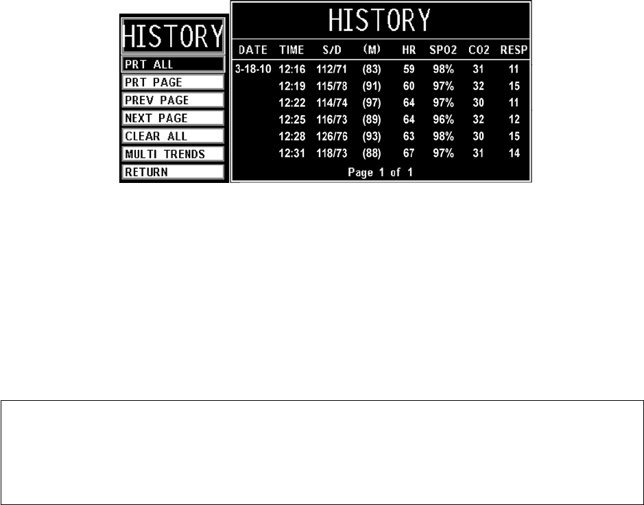
3-16
Figure 3-12. The HISTORY Menu
The following options are available in the History Menu:
(1) PRT ALL. Selecting this menu option prints all stored Tabular Data.
(2) PRT PAGE. Selecting this menu option prints the current page.
(3) PREV PAGE. Selecting this menu option allows the selection of the
previous page of tabular data.
(4) NEXT PAGE. Selecting this menu option allows the selection of the next
page of the tabular data.
(5) CLEAR ALL. Selecting this menu option clears the patient Trend Data.
(6) MULTI TRENDS. Selecting this menu option will bring up the
MultiTrends Menu where the operator may configure Multiple Trends for
display.
(7) RETURN. Selecting this menu option will return the display to the NIBP
Menu.
e. FORMAT. Selecting this menu option allows the operator to change the display
format of the Pressure numerics. If SYS/DIA is selected, the Systolic and Diastolic
numerics will be in a large font separated by a “slash” and the Mean numeric will
be in a smaller font bracketed with parenthesis. If MEAN is selected, the Mean
numeric is displayed in the large font with the Systolic and Diastolic numerics
separated by a “slash” in a smaller font.
f. RETURN. Selecting this menu option will return the display to the Normal
Screen.
NOTE
History Data is retained when a new patient is connected to the system. Therefore, to
avoid confusion, all previously acquired data must be cleared prior to connection to a
new patient. This is accomplished by pressing CLEAR ALL and following all
associated commands to clear all previous patient data.

3-17
3.2.6 Using the Automatic NIBP Interval Mode. This system may be setup to take NIBP
readings automatically at intervals set by the operator. To set this system to make Automatic
NIBP determinations, turn the Rotary Knob until the NIBP Menu-Select Icon is highlighted and
then press the Rotary Knob to bring up the NIBP Menu. To set the Interval Time, highlight the
INTERVAL Menu selection and press the Rotary Knob to access the Time Selection menu. To
turn the Automatic Mode of Operation ON or OFF, highlight the AUTO MODE Menu selection,
press the Rotary Knob and select ON or OFF. Once the Automatic Mode has been turned ON,
press the NIBP START/STOP Control Key to activate.
3.2.7 Manually Starting/Stopping an NIBP Reading Cycle. An NIBP cycle may be started or
stopped by pressing the NIBP START/STOP or STANDBY Control Key.
3.2.8 NIBP STAT Mode Operation. The STAT Mode is specifically intended for clinicians who
need to obtain successive readings for rapid assessment of the trend of a patient's pressures. To
initiate a series of up to five STAT Readings, the operator presses the NIBP STAT Control Key.
The system will perform up to five NIBP cycles in a period of five (5) minutes. At the end of the
five (5) minute period, the STAT Mode will terminate (even if a reading is in progress) regardless
of how many readings have been completed.
3.2.9 NIBP Alarm Limits. Alarm Limits may be set two ways. To set the Alarm Limits for
every available parameter, from the Normal Screen (with no icons highlighted), press the
ALARMS SCREEN Menu-Select Key. To set the Alarm Limits for NIBP only, highlight the
NIBP Icon and press the ALARMS SCREEN Menu-Select Key to access the individual
Parameter Alarm Limits box.
3.2.10 NIBP Adult vs. Neonatal Mode Operation. This system allows the operator to determine
pressures on a wide range of patients by allowing the Patient Type to be switched from ADULT to
NEO (Adult Mode is used for Adult and Pediatric patients and Neonate Mode is used for
Neonates only). Several operational parameters (including cuff inflation pressure) are varied
depending on the setting of the Patient Menu Option in the Setups Menu. The Adult/Pediatric
Mode uses a higher pump volume and a much larger cuff is used on the patient; in the Neonatal
Mode the pump rate is lower and a much smaller cuff is used on the patient (See Accessories for
“NIBP” on page xvii of this manual for cuff selection and sizes). The Alarm Limits change when
the patient type is switched from ADULT to NEO (or NEO to ADULT).
Whenever the NIBP Patient Mode is switched (either from ADULT to NEO or NEO to ADULT),
for 20 seconds the Alarm Tone will sound while the informational display message area indicates
“Change NIBP Cuff.” To change the patient type, press the SETUP Control Key, scroll to the
Patient Menu Selection and press the Rotary Knob. The “WRONG CUFF” NIBP message will
appear if a reading is initiated and the system detects that an incorrect cuff is being used for the
selected patient mode (ADULT or NEO). Replace the patient cuff with the appropriate size cuff
and press the NIBP START/STOP control a second time, this will re-initiate the reading.
NOTE
NIBP AUTO mode is suspended while in STANDBY mode.
WARNING
The patient's blood pressure determinations are not continuous. The blood
pressure determinations are only updated immediately after a blood pressure
measurement is taken. When set to the shortest of the automatic intervals, the
constant measurements can cause blood pooling in the limb. Blood pooling in
the limb will artificially increase the value of the blood pressure determinations.
WARNING
The initial cuff inflation pressure will increase to 170 mmHg when changing the
patient mode from Neonate to Adult.

3-18
3.2.11 NIBP Trended Data. For complete information on the trending of patient NIBP data, see
Section 5, Recording and Trending.
3.2.12 NIBP Messages. The following is a list of messages that may be displayed during NIBP
monitoring:
.
CALIB Displayed if the system detects that the NIBP section is out of
calibration.
CHANGE NIBP
CUFF
Displayed for 30 seconds whenever the Patient Mode is switched
between Adult and Neonate.
CUFF LEAK Displayed if the system detects a leak in the cuff during the last
reading attempt. This message is also displayed, with other
messages, between reading attempts to provide a visual indication
that a leak was detected in the cuff during the previous reading
attempt.
CUFF=XXX Displayed while the system is making an NIBP determination.
Provides a visual indication of the actual pressure of the cuff
throughout the measurement.
ET=XXX Indicates the time since the last NIBP measurement was
completed.
LONG PRESS Displayed if the system detects cuff pressure remaining the same
for more then 30 seconds or if a reading has been in progress for
more than 150 seconds for adults (80 seconds for neonates).
NOT INFLATING Displayed if the system detects the cuff inflation cycle running
longer than 30 seconds for adults (6 seconds for neonates).
OVER PRES Displayed if the system detects a cuff pressure of 285 mmHg
(adult, 150 neonate) or higher.
RESIDUAL PRES Displayed if the system detects that cuff pressure remains above
20 mmHg for more then 2.5 minutes.
WRONG CUFF Displayed if the system detects that an incorrect cuff is being used.
Select the appropriate cuff for the patient.
NOTE
When positioning the SpO2 sensor, special care must be taken to avoid applying
excessive pressure and the maximum application time is reduced to two (2) hours.
WARNING
Probes are designed for use with specific patient monitoring systems. The
operator is responsible for checking the compatibility of the system, probe, and
cable before use. Incompatible components can result in degraded
performance.
NOTE
Refer to the facility's biohazard procedure for disposal of SpO2 grip sensors when they
become unusable. Usually sensors are disposed of as medical waste per hospital
procedures as they are likely to be contaminated.
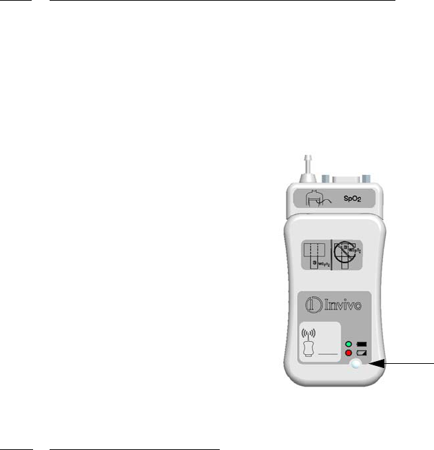
3-19
3.3 SpO2 Monitoring. The SPO2 Menu is brought up (if this parameter is turned on through
the Setups Menu) with the SPO2 Menu-Select Icon.
The following three secondary menus support the SpO2 monitoring feature:
•RECORDER Menu. Used to select Recorder functions and to set the Recorder
and Trace Speed.
•ALARMS Menu. Used to Set and/or Disable the SpO2 Alarms. The range of
Alarm Limits for SpO2 is 50 to 99%, Off.
•SpO2 TREND Menu. Used to setup and print Trended information.
3.3.1 Wireless SpO2 Module and Fiber-Optic SpO2 Sensor. The Invivo Wireless SpO2 Module
(Part Number 9311,
See Figure 3-13
) and Fiber-Optic SpO2 Sensor are designed for use in the MRI
environment. The Fiber-Optic SpO2 Sensor is specifically designed for use in the MRI system bore
and can be placed within the MRI procedure Field-Of-View (FOV), although the Wireless SpO2
Module must be kept outside of the MRI system bore. Placing the Wireless SpO2 Module inside the
MRI system bore may interrupt SpO2 monitoring during the MRI procedure.
Use only the Fiber Optic SpO2 sensor (Part Number 9399B) designed for the Precess Wireless
SpO2 Module. Connecting a SpO2 sensor other than Part Number 9399B into the Wireless SpO2
Module will cause inaccurate SpO2 readings and may damage the Wireless SpO2 Module.
Figure 3-13. Wireless SpO2 Module
3.3.2 SpO2 Sensor Positioning. The monitoring site, sensor position, sensor connection and the
ambient environment all have possible impacts on the operation of the Precess MRI Patient
Monitoring System. The following is a list of possible messages (which are indicated in the SpO2
display), causes, and possible solutions:
a. LOW LIGHT. The transmission of the light is partially blocked. The tissue at the
site may be too opaque and/or thick. If the sensor is positioned on the finger, check
the fingernails for nail polish, long fingernails and artificial fingernails; remove
fingernail polish completely, for artificial nails: use a Multi-Site sensor at another
location, and, for long fingernails: either trim the nails or use a Multi-site sensor at
another location.
b. PROBE OFF. The sensor is not sensing or detecting the patient's pulse. There are
two possible causes of this, either the sensor is not detecting the pulse or the sensor
is receiving too much light to operate. Check the ambient lighting, if a light is
shining directly into the sensor, reposition the sensor to a darker area or cover the
sensor to cut down the light entering the sensor. Check the sensor cable connection
for proper connection. Try a different sensor.
c. SEARCHING. The system is searching for a good pulse. Give the system time to
lock onto a good pulse.
Power/Communication LED
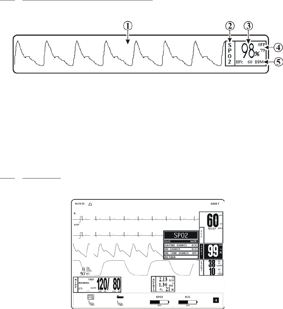
3-20
d. LOW QUAL. The signal correlation between the red and infrared light channels is
too low for accurate saturation calculation. Contact Invivo Technical Service for
further assistance.
3.3.3 Associated SpO2 Waveforms and Displays. (See Figure 3-14) If the SpO2 is turned on
the waveform is displayed in Trace Location C and the numerical information in Box 2. The
following is a description of the items contained within the SpO2 Display:
Figure 3-14. SpO2 Display
a. SpO2 Waveform. (Item 1) The SpO2 Waveform is displayed in Trace
Location C.
b. Icon Label. (Item 2) This label identifies the Parameter numerics that are
displayed within this box. SpO2 is monitored using Box 3.
c. SpO2 Numeric. (Item 3) A numeric indication of the patient's SpO2 reading.
d. SpO2 High and Low Alarm Limits. (Item 4) A numeric indication of the settings
of the High and Low SpO2 Alarm Limits.
e. Heart Rate. (Item 5) Heart Rate Value derived from SpO2.
3.3.4 SpO2 Menu. (See Figure 3-15) The menu for the SpO2 is brought up with the selection
of the SPO2 Menu-Select Icon. This menu has a time-out feature. If no action is taken for
approximately 60 seconds, the display will automatically return to the Normal Screen.
Figure 3-15. The SpO2 Menu
The following is a description of the SPO2 Menu options:
a. SIZE. (See Figure 3-16.) Selecting this menu option provides the operator with
the ability to change the Size of the SpO2 pulse waveform. The options are 10%,
20%, 40% (default), 60%, 80% and 100%.
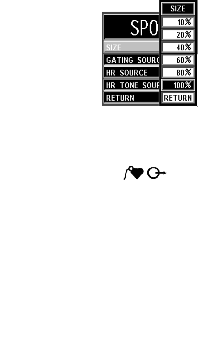
3-21
Figure 3-16. The SpO2 SIZE Menu
b. GATING SOURCE. Selecting this menu option allows the selection of the
Source to be used for MRI Gating. The options are ECG and PULSE. The MRI
Gating connector is located at the back of the WPU. This connector is denoted by
the symbol below. An optional gating interface cable is needed to connect the
Precess system to various manufacturers’ MRI systems.
c. HR SOURCE. Selecting this menu option allows the selection of the Source to be
used for the Heart Rate display in the ECG area. The options are AUTO, ECG
(default), ART (arterial pressure), SPO2 and NIBP.
This menu option is identical to, and interactive with, similarly named menu
options under ECG and NIBP.
d. HR TONE SOURCE. Selecting this menu option selects the Heart Rate Tone
Source. The options are QRS, SPO2 and OFF (default). When the Source is the
QRS, the Tone sounds at the detection of QRS from the ECG Parameter. When the
Source is the SpO2, the Tone sounds at the detection of the pulse from the SpO2
Parameter.
The Pulse Tone is modulated by the SpO2 value. The pitch will be at the lowest
frequency when its value is at the low end of scale.
This menu option is identical to, and interactive with, the HR Tone Source Option
in the Sound Adjust and ECG Menus.
e. RETURN. Selecting this menu option will return the display to the Normal
Screen.
3.3.5 SpO2 Alarm Limits. Alarm Limits may be set two ways. To set the Alarm Limits for
every available Parameter, from the Normal Screen (with no icons highlighted), press the
ALARMS SCREEN Menu-Select Key. To set the Alarm Limits for SpO2 only, highlight the
SpO2 Icon and press the ALARMS SCREEN Menu-Select Key to access the individual
Parameter Alarm Limits Box. The range of Alarm Limits for SpO2 is 50 to 100%.

3-22
3.3.6 SpO2 Trended Data. For complete information on the Trending of patient SpO2 data, See
Section 5.0, Recording and Trending.
3.3.7 SpO2 Messages. The following is a list of messages that may be displayed during SpO2
monitoring
NOTE
The SpO2 waveform is normalized, it is auto scaled to fit the display width. Signal
inadequacy is indicated by a LOW QUAL message.
BAD PROBE The Precess MRI Patient Monitoring System has sensed a
shorted or open connector in the sensor. Contact Invivo
Technical Service for further assistance.
LOW LIGHT The transmission of the light is partially blocked. The tissue at
the site may be too opaque and/or thick. If the sensor is
positioned on the finger, check the fingernails for nail polish,
long fingernails and artificial fingernails; remove fingernail
polish completely, for artificial nails: use a Multi-Site sensor at
another location, and, for long fingernails: either trim the nails
or use a Multi-site sensor at another location.
LOW QUAL The signal correlation between the red and infrared light
channels is too low for accurate saturation calculation. Contact
Invivo Technical Service for further assistance.
PROBE OFF The sensor is not sensing or detecting the patient's pulse. There
are two possible causes of this, either the sensor is not detecting
the pulse or the sensor is receiving too much light to operate.
Check the ambient lighting, if a light is shining directly into the
sensor, reposition the sensor to a darker area or cover the probe
to cut down the light entering the sensor. Check the sensor cable
connection for proper connection. Try a different sensor.
SEARCHING The system is searching for a good pulse. Give the system time
to lock onto a good pulse.
HW FAIL The system has detected a hardware failure. Remove the system
from service immediately and refer it to Invivo qualified service
personnel for repair. This system must not, for any patient that
requires accurate SpO2 measurement, ever be placed back into
service before the repair is performed.

3-23
3.4 End-tidal CO2 (ETCO2) Monitoring. The ETCO2 Menu is brought up (if this
Parameter is turned on through the Setups Menu) with the ETCO2 Menu-Select Icon. The ETCO2
feature provides sidestream measurement of CO2 with a continuous real-time CO2 Waveform
Display. This feature will perform an automatic zeroing at periodic intervals while continuously
performing pressure corrections. ETCO2 monitoring also provides Respiration Monitoring.
The following three secondary menus support the ETCO2 monitoring feature:
•RECORDER Menu. Used to select Recorder functions and to set the Recorder
and Trace Speed.
•ALARMS Menu. Used to Set and/or Disable the ETCO2 Alarms. The range of
Alarm Limits for ETCO2 is 5 to 80 mmHg.
•ETCO2 TREND Menu. Used to Setup and Print Trended information.
3.4.1 Water Trap and Sampling Line Preparation. The accuracy of the data collected is greatly
influenced by the proper use, fitting and maintenance of the sampling tubing, water trap and nasal
cannula or airway adapter.
a. The patient sampling circuit (See Figure 3-17) consists of the blue (1 mm)
sampling line, Part Number 94021, and either a sampling nasal cannula or a airway
adaptor connected to a patient airway. All fittings in the circuit are Luer-Lock type.
All fittings must be fitted together securely to keep them from separating during
the procedure, and to ensure proper sampling without the introduction of outside
air. Loose fitting will result in gas measurement errors.
b. Nasal Cannula. The nasal cannula is of the “around-the-ear” type. Place the nasal
prongs gently inside the nose, loop the excess tubing over the patient's ears and
then down under the chin. The cannula may then be fitted by sliding the plastic
ring up until the cannula is secure and comfortable.
NOTE
End-tidal CO2 (ETCO2) monitoring allows exhaled CO2 to be measured non-
invasively. The Precess™ with ETCO2 feature is intended to monitor inspired and
expired levels of CO2 through a sampling tube.
Before using the ETCO2 monitoring feature, connect the Gas Exhaust output at the
rear of the Precess™ WPU to the facility gas scavenging system utilizing 0.25 inch
(6 mm) inside diameter tubing.
Do not block the gas exhaust port on the rear of the WPU.
The time from switching “ON” the ETCO2 portion of the Precess™ to obtaining
specified operating performance is 2 minutes.
CAUTION
Before using the ETCO2 analyzer, read the PRECAUTIONS and USER
RESPONSIBILITIES which follow the Table of Contents
(Pages v through xiii).
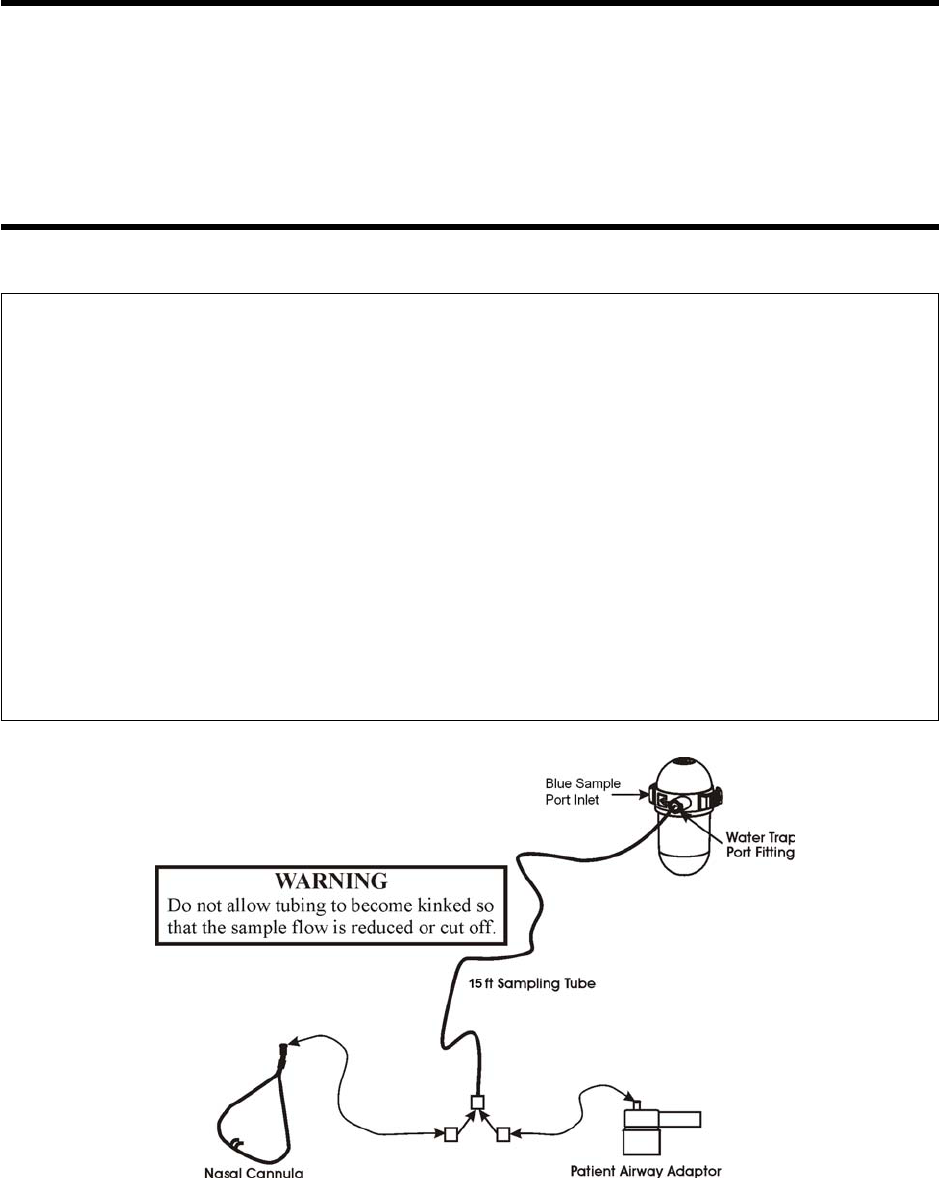
3-24
c. Patient Airway Adaptor. When using the patient airway adaptor, attach the
sample line to the airway adapter. Install the airway adapter into the patient circuit
tubing. Take great care not to dislodge or move the patient circuit tube when
attaching the adaptor.
Figure 3-17. The Patient Sampling Circuit
CAUTION
Do not allow the tubing to become kinked so that the sample flow is reduced or cut off.
Be careful that the tubing remains clear of any table moving mechanisms which may
kink or cut the tubing.
Always discard the Water Trap when it becomes filled. Do not attempt to clean or reuse
the Water Trap. Accidental water ingress into the Precess MRI Patient Monitoring
System can affect the gas measurements.
NOTE
Always inspect patient tubing after attachment to the Precess MRI Patient Monitoring
System by following the patient tubing manufacturer's recommendations.
It is recommended that the sampling line is changed after each patient use.
An internal leak may result in condensation within the system. If this is suspected,
please contact Invivo.
An ETCO2 Low Flow Alarm indicates the following:
1. A sample line is not connected to the water trap.
2. The gas exhaust port is obstructed.
3. Use of a sample line other than Invivo Part Number 94021.
The Precess™ contains an exhaust port at the rear of the WPU that may be connected
to the facility's anesthetic gas scavenging system, using the appropriate exhaust tube
accessory. Follow the facility's guidelines for connecting to the scavenging system,
including proper disposal of sampled gas.
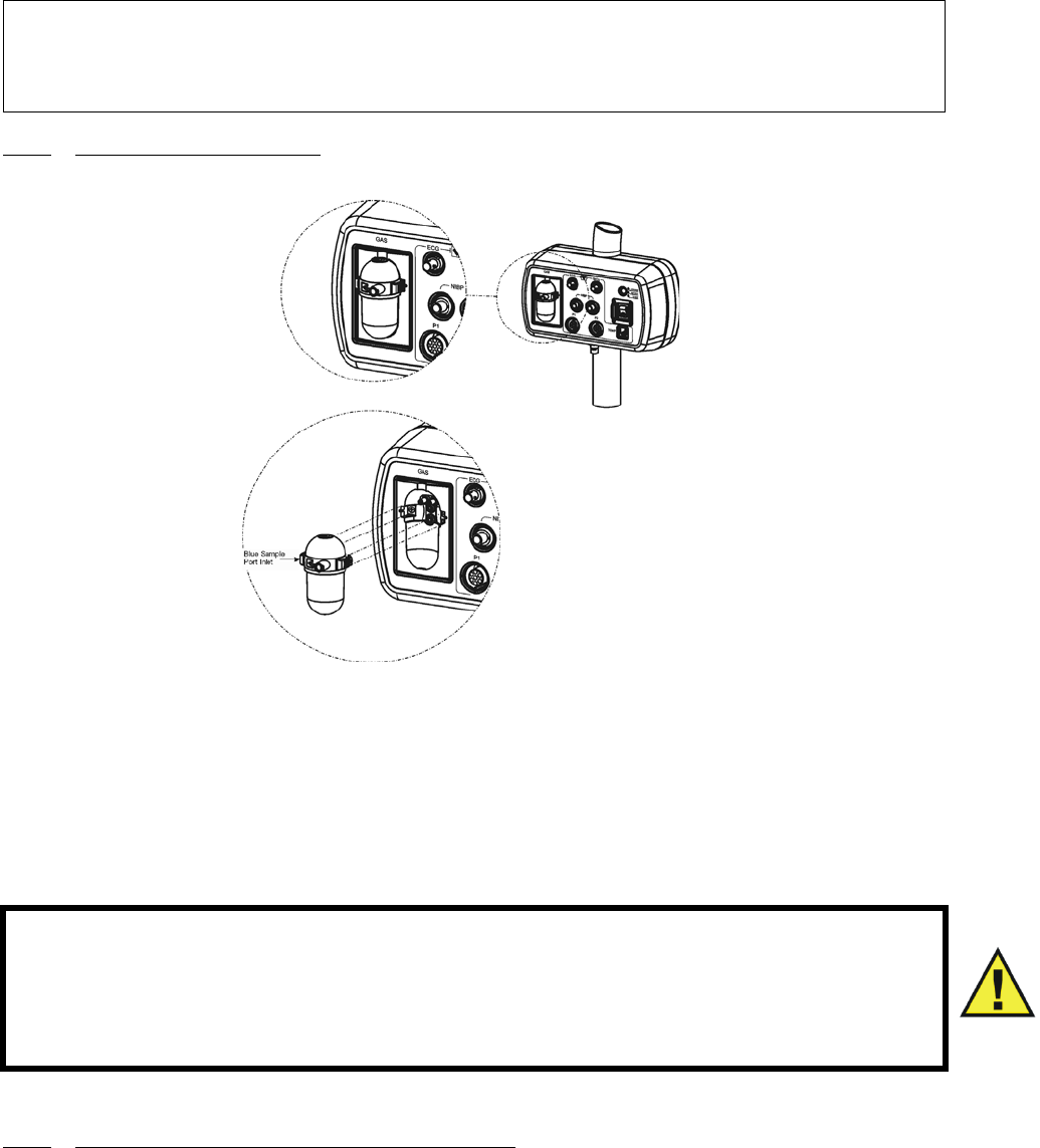
3-25
3.4.2 Water Trap Replacement. (Figure 3-18) Remove the sample line from the Water Trap
port and perform the following to replace the Water Trap:
Figure 3-18. Water Trap Installation Diagram
a. To remove the Water Trap, simultaneously press the two release tabs (located on
the left and right side of the trap near the top) and pull the Water Trap from the
enclosure.
b. To install the Water Trap, line the trap up with the enclosure (the enclosure is
shaped to the Water Trap) and press it into place until there is an audible “click”
from both of the release tabs.
c. Attach sample line to Water Trap port.
3.4.3 Associated ETCO2 Waveforms and Displays. (See Figure 3-19) ETCO2 information is
displayed as a waveform in Trace Location D and numeric data in ETCO2 box. The following is a
description of the items contained within the ETCO2 Display:
NOTE
The Water Trap must be checked every eight (8) hours and replaced as necessary.
Disposal of water traps must be done according to the facilities biohazard procedure.
WARNING
Always test sampling line adapter for a tight connection and proper operation
before attaching to a patient.
Overtightening the sampling line may damage the water trap. Tighten the
sampling line no more than 1/2 turn.
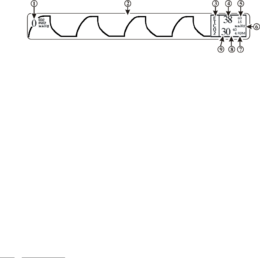
3-26
Figure 3-19. The ETCO2 Display
For optimum fit and compatibility, Invivo strongly recommends the use of the Invivo CO2
Sampling Kit (Part Number 94021), which contains the ETCO2 sample line tubing.
a. Inspired CO2 Numeric. (Item 1) A numeric indication of the patient's Inspired
CO2 reading.
b. Respiration Waveform. (Item 2) The ETCO2 derived Respiration Waveform is
displayed in Trace Location D.
c. Icon Label. (Item 3) This label identifies the parameter numerics that are
displayed within this box.
d. ETCO2 Numeric. (Item 4) A numeric indication of the patient's ETCO2 reading.
e. ETCO2 Alarm Limits. (Item 5) A numeric indication of the settings of the High
(on top in the example) and Low (bottom in the example) ETCO2 Alarm Limits.
f. Unit of Measurement. (Item 6) Displays the Unit of Measurement being used for
presentation of the ETCO2 numeric data.
g. Unit of Measurement. (Item 7) Displays the Unit of Measurement being used for
presentation of the ETCO2 derived Respiration numeric data.
h. Respiration Alarm Limits. (Item 8) A numeric indication of the settings of the
High (on top in the example) and Low (bottom in the example) Respiration Alarm
Limits when derived from the ETCO2 module.
i. Respiration Numeric. (Item 9) A numeric indication of the patient's Respiration
reading derived from the ETCO2 module.
3.4.4 ETCO2 Menu. (See Figure 3-20) The menu for the ETCO2 is brought up with the
selection of the ETCO2 Menu-Select Icon. This menu has a time-out feature. If no action is
taken for approximately 60 seconds, the display will automatically return to the Normal Screen.
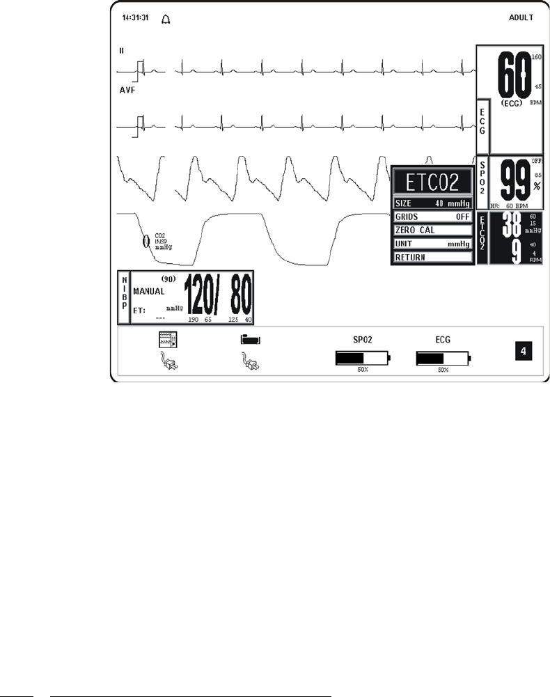
3-27
Figure 3-20. The ETCO2 Menu
The following is a description of the ETCO2 Menu Options:
a. SIZE. Selecting this menu option brings up the SIZE Menu where the operator
may select 40, 60 or 80 mmHg for the Scale Size of the ETCO2 Waveform
Display.
b. GRIDS. Selecting this menu option brings up the GRIDS Menu where the
operator may turn the ETCO2 Grids ON or OFF.
c. ZERO CAL. Selecting this menu option causes the Precess MRI Patient
Monitoring System to perform the Zero Calibration routine.
d. UNIT. Selecting this menu options brings up the UNIT Menu where the operator
may toggle the unit between mmHg and kPa.
e. RETURN. Selecting this menu option will return the monitor to the Normal
Screen.
3.4.5 Calibration of CO2 Measurement System. The system will perform automatic Zero
Calibration cycles as part of its normal function. The Zero Calibration cycle is discussed below.
a. Zero Calibration Cycle. A Zero Calibration cycle consists of the realignment of
the Zero point. During this calibration, the system makes sure that a concentration
of 0% is measured when room air is flowing through its sample chamber. During a
Zero Calibration cycle the system performs the following steps:
(1) Switches the input gas valve to the Zero Intake Port placed on the bottom
of the WPU Patient Connection Module.
(2) Room air is absorbed through the Zero Intake Port and flushes the
pneumatic system for a few seconds.
(3) Once the channel readings have stabilized, a snapshot is taken and the Zero
point is realigned using these readings as a reference.

3-28
(4) The Input Gas Valve is then switched back to the normal position and the
gas being measured is given a few seconds to flush the pneumatic system
to clear out the room air.
(5) After the readings stabilize, the ETCO2 system begins it’s normal
functioning routine.
b. Automatic Zero Calibration Cycles. An Automatic Zero Calibration cycle is
triggered when certain time intervals have passed since the system has completed
its warm-up cycle. The timetable for Automatic Zero Calibration cycles is the
following: Immediately after the ETCO2 parameter is activated; 30 minutes after
activation, 90 minutes after activation, then every two hours after that.
c. ETCO2 Gas Calibration Test. Perform the following to test the ETCO2 Gas Cal
system:
(1) Turn on the ETCO2 icon as follows:
(a) Press the SETUP Control Key.
(b) Turn the Rotary Knob to highlight the PARAMETER SELECTION
Option.
(c) Press the Rotary Knob to bring up the PARAMETER SELECTION
Menu.
(d) Turn the Rotary Knob until the ETCO2 Menu selection is
highlighted.
(e) Press the Rotary Knob to select ETCO2.
(f) Turn the Rotary Knob until the ON Menu Option is highlighted.
(g) Press the Rotary Knob to select ON.
(h) Press the NORMAL SCREEN Control Key to display the Normal
Screen.
(2) Allow the ETCO2 Bench to warm up for approximately 25 minutes.
(3) Perform ETCO2 Validation Calibration Test as follows:
(a) Connect the aerosol QC CHECK GAS can (Invivo Part Number
9034F) to the GAS (ETCO2) port on the water trap.
(b) Apply the gas to the GAS port for a minimum of 30 seconds, then
verify the following upper numeric value in the ETCO2 icon:
• ETCO2 = 38 (±4) mmHg.*
(c) Disconnect the QC CHECK GAS can from the system.
NOTE
To perform Zero Calibration, the system pulls ambient air through the Patient
Connection Module (PCU) CO2 Zero Intake Port. The Calibration system assumes
that the ambient air will contain normal amounts of trace CO2. If this system is placed
in an unventilated area that allows CO2 (from the rear panel CO2 Exhaust Port - if not
connected to a Gas Scavenging System) to accumulate, the result could be inaccurate
Zeroing of the ETCO2 module and resulting inaccurate patient readings.
NOTE
*This CO2 reading varies according to altitude. The above reading indicates the
expected CO2 value to be observed when conducting this test on the Precess MRI
Patient Monitoring System located at sea level (or 0 altitude).

3-29
3.4.6 ETCO2 Alarm Limits. Alarm Limits may be set two ways. To set the Alarm Limits for
every available parameter, from the Normal Screen (with no icons highlighted), press the
ALARMS SCREEN Menu-Select Key. To set the Alarm Limits for ETCO2 only, highlight the
ETCO2 Icon and press the ALARMS SCREEN Menu-Select Key to access the individual
parameter Alarm Limits Box. The range of Alarm Limits for ETCO2 is 5 to 60 mmHg and OFF
for the Low Limit, and 5 to 80 mmHg and OFF for the High Limit.
Inspired CO2 has a fixed high alarm limit of 25 mmHg. When this upper threshold is exceeded,
the Inspired CO2 numeric flashes RED in color and the Alarm Tone sounds.
3.4.7 ETCO2 Trended Data. For complete information on the trending of patient ETCO2 data,
see Section 5, Recording and Trending.
3.4.8 ETCO2 Messages. The following is a list of messages that may be displayed during
ETCO2 monitoring:
3.5 Anesthetic Agent/Oxygen Monitoring. (Optional) The Anesthesia Gas Sensor (AGS) is
a non-dispersive, single path Infra-Red spectrometer based upon a high stability IR sensor
technology known as Stabilized Thermopile Bridge (STB). Utilizing the STB technology, the
Invivo AGS yields high output, low noise and ultra stable gas measurements.
The following two secondary menus support the Anesthetic Agent/Oxygen monitoring feature:
•RECORDER Menu. Used to select Recorder functions and to set the Recorder
and Trace Speed.
•ALARMS Menu. Used to Set and/or Disable the Agent Alarms.
NOTE
Press the ALARM SILENCE Control Key to silence the fixed inspired CO2 alarm.
CO2 OCCLUSION The air lines have become blocked. Check exposed hose
for kinks and blockages. If blockage appears to be internal
to the unit, contact a Qualified Service Representative.
ETCO2: HW FAIL The ETCO2 has failed, contact a Qualified Service
Representative.
ETCO2 WARMING UP The ETCO2 is warming up in preparation for use. The
warm-up cycle is approximately two (2) minutes.
READJUSTING CO2
ZERO
The ETCO2 module is performing its automatic Zero
Adjustment Routine.
ETCO2: LOW FLOW The ETCO2 Low Flow Alarm indicates the one or more of
the following: A sample line is not connected to the water
trap; the gas exhause port is obstructed; or a sample line
other than Invivo Part Number 94021 is being used.
NOTE
Before using the Agents monitoring feature, connect the Gas Exhaust output at the
rear of the Precess ™ WPU to the facility gas scavenging system utilizing 0.25 inch
(6 mm) inside diameter tubing.

3-30
3.5.1 Anesthetic Agent Patient and Tubing Preparation. Use only Invivo sampling lines and
accessories (Part Number 94018); other sampling lines may cause inaccurate readings. It is
recommended that the sampling line and airway adapter are changed after each patient use.
3.5.2 Associated Anesthetic Agent Displays. (See Figure 3-21) Anesthetic Agent information
is only displayed as numeric data. The Agent identification and measurement are individually
performed on both inspired and expired gases. With any two mixtures involving gases
Sevoflurane, Isoflurane, and Desflurane, the inspired primary anesthetic agent (the gas with the
highest concentration) is displayed with its ID and concentration in the Fi location of the Agent
Icon box. The expired primary anesthetic agent is displayed with its ID and concentration in the
Et location of the Agent Icon box. An alarm sounds and “MULTIPLE AGENTS” is displayed any
time two or more anesthetic agents are detected. If Halothane or Enflurane are involved in any
mixture of anesthetic agents, “---” may appear in the Fi and/or Et location while a pure inspired or
expired gas is displayed in its appropriate location. See Table 3 -2 and Table 3-3 for a complete
description of the Agent Display during mixed Agent conditions.
Figure 3-21. Anesthetic Agents Display
The following is a description of the items contained within the Anesthetic Agent Display.
a. Icon Label. (Item 1) This label identifies the Parameter numerics that are
displayed within this box.
b. Agent Expired Numeric. (Item 2) A numeric indication of the value of the gas
being expired.
c. Agent Inspired Numeric. (Item 3) A numeric indication of the value of the gas
being inspired.
d. Anesthetic Agent Designation. (Items 4 and 5) Displays the identification of the
gas being monitored. The Agent Identifications are as follows:
(1) Halothane HAL
(2) Isoflurane ISO
(3) Sevoflurane SEV
(4) Desflurane DES
(5) Enflurane ENF
WARNING
Always test sampling line adapter for a tight connection and proper operation
before attaching to a patient.
Overtightening the sampling line may damage the water trap. Tighten the
sampling line no more than 1/2 turn.

3-31
e. Et. (Item 4) Indicates that the top row numeric is the End Tidal (expired) values of
the gas being monitored (with the designation of the gas located just below Et).
f. Fi. (Item 5) Indicates that the bottom row numeric is the fraction of inspired (Fi)
values of the gas being monitored (with the designation of the gas located just
below Fi).
g. Unit of Measurement. (Item 6) Displays the Unit of Measurement being used for
presentation of the Anesthetic Agents and Oxygen numeric data (i.e. Percentage).
h. Oxygen Numeric. (Item 7) A numeric indication of the patient’s Oxygen
measurement.
i. O2. (Item 8) Indicates that the patient’s oxygen is being monitored in this row.
Table 3-2. Agent Display During Mixed Agent Conditions
NOTE
The presence of Enflurane (ENF) will be detected, but a concentration value will not be
provided.
Display
MULTIPLE
AGENTS
Message
Physical Gas
Sevoflurane, Isoflurane, Desflurane or any
mixture of two where the gas with the highest
concentration is considered primary.
Agent Display
Inspired
(Fi)
Expired
(Et)
Fi ID
%Inspired
Concentration
Et ID
%Expired
Concentration
No Agent 1 Agent 1 Agent 1 Agent 1
Yes Agent 1 Agent 2 Agent 1 Agent 2
Yes Agent 2 Agent 1 Agent 2 Agent 1
Yes Agent 1 - Primary
Agent 2 - Secondary
Agent 1 - Primary
Agent 2 - Secondary
Agent 1 Agent 1
Yes Agent 2 - Primary
Agent 1 - Secondary
Agent 1 - Primary
Agent 2 - Secondary
Agent 2 Agent 1
Yes Agent 2 - Primary
Agent 1 - Secondary
Agent 2 - Primary
Agent 1 - Secondary
Agent 2 Agent 2
Yes Agent 1 - Primary
Agent 2 - Secondary
Agent 1 Agent 1 Agent 1
Yes Agent 2 - Primary
Agent 1 - Secondary
Agent 1 Agent 2 Agent 1
Yes Agent 1 - Primary
Agent 2 - Secondary
Agent 2 Agent 1 Agent 2
Yes Agent 2 - Primary
Agent 1 - Secondary
Agent 2 Agent 2 Agent 2
Yes Agent 1 Agent 1 - Primary
Agent 2 - Secondary
Agent 1 Agent 1
No - - --- ---
Yes Agent 1 Agent 2 - Primary
Agent 1 - Secondary
Agent 1‘ Agent 2
Yes Agent 2 Agent 2 - Primary
Agent 1 - Secondary
Agent 2 Agent 2
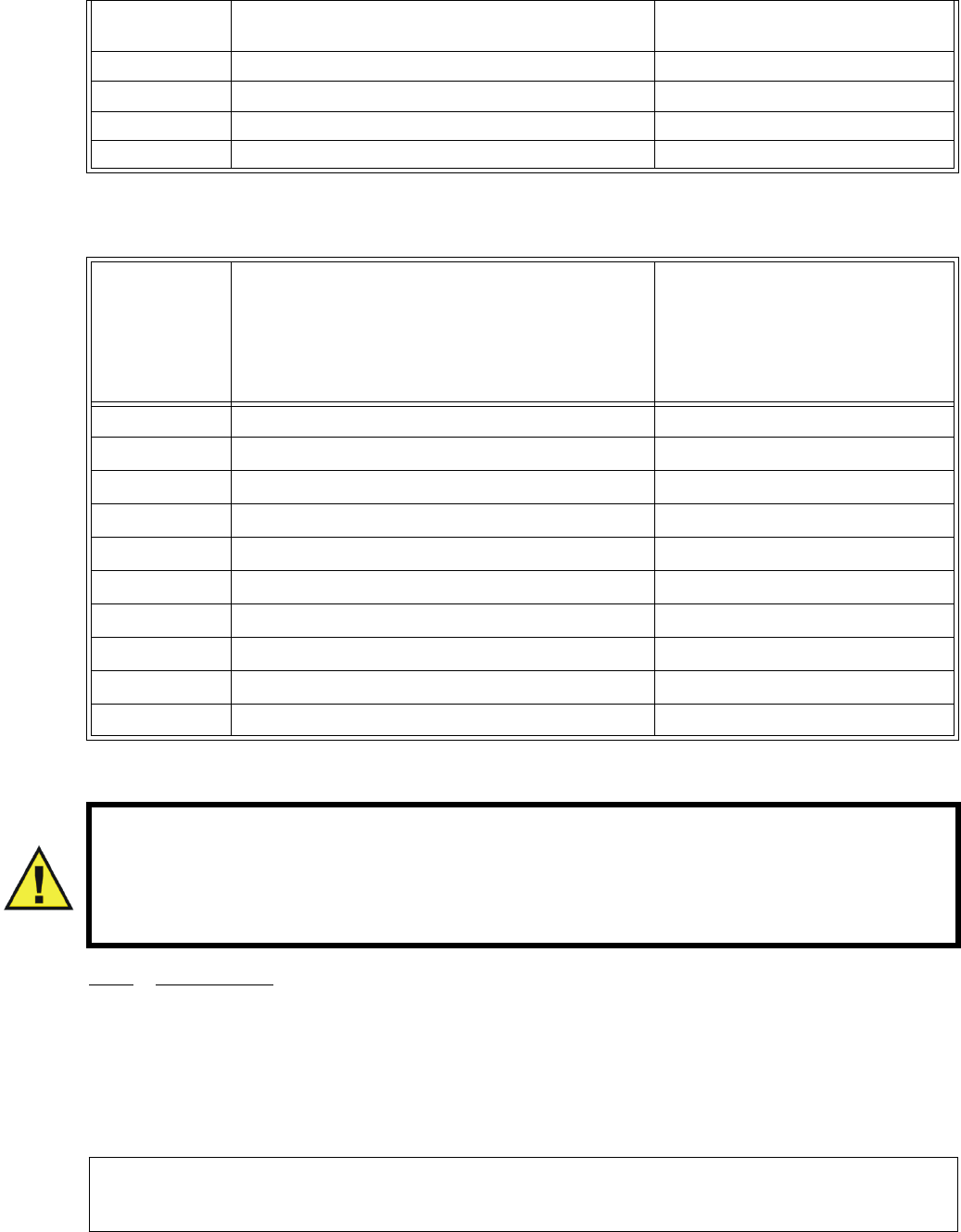
3-32
Table 3-3. Agent Display During Mixed Agent Conditions
3.5.3 Agent Menu. The Anesthetic Agent monitoring feature does not have a menu like the
other monitoring features on this system. Pressing the Rotary Knob while the AGENTS icon is
highlighted brings up a box which displays the Minimum Alveolar Concentration (MAC) values.
1 MAC Values used to Calculate the displayed MAC are as follows: HAL=0.76%, ISO=1.12%,
SEV=1.92%, DES=6.0% and N2O=100%.
Calculation of displayed MAC value: Cal. MAC = (EtN2O/1 MAC N2O) + (Et Agent/1 MAC
Agent).
Yes Agent 2 Agent 1 - Primary
Agent 2 - Secondary
Agent 2 Agent 1
No Agent 1 - Agent 1 ---
No - Agent 1 --- Agent 1
No Agent 2 - Agent 2 ---
No - Agent 2 --- Agent 2
Display
MULTIPLE
AGENTS
Message
Physical Gas
Halothane and involved mixes. Agent Display
Inspired
(Fi)
Expired
(Et)
Fi ID
%Inspired
Concentration
Et ID
%Expired
Concentration
No Agent 1 Agent 1 Agent 1 Agent 1
Yes Agent 1 Agent 2 Agent 1 ---
Yes Agent 1 Mix Agent 1 ---
Yes Mix Agent 2 --- Agent 2
Yes Mix Mix --- ---
No Agent 1 - Agent 1 ---
Yes Mix - --- ---
No - Agent 2 --- Agent 2
Yes - Mix --- ---
No - - --- ---
WARNING
Minimum Alveolar Concentration (MAC) values are empirical and are not
absolute values. Invivo's AGS MAC values correspond to those of healthy adults
and cannot be applied to children. Age and other individual factors influencing
the behavior of volatile agents are not taken into account.
NOTE
Mixed concentration of Agents are not included in the MAC calculations.

3-33
3.5.4 Gas Calibration. The system performs a Zero Calibration periodically and the operator
may also manually initiate a Zero Calibration cycle. There is a two (2) minute warm-up period
when Agents is first turned on during which there is no monitoring. The entire warm-up period is
20 minutes during which the system will perform an automatic Zero Calibration at the two minute
mark in the warm-up period, then will run again in the following sequence: 4, 6, 8, 10, 12, 14, 16,
18, 20, 40 and 60 minutes. After the 60 minutes has expired the Zero Calibration will run once an
hour, or whenever an anesthetic agent change is detected.
On the WPU only, if the Agents Option is run over a continuous 12-hour period with an O2
concentration of 22% or greater, a WARNING will appear to alert the operator that a one (1)
minute O2 Calibration sequence must be run. The warning box will offer the operator a YES/NO
option of running the one (1) minute O2 Calibration sequence; if the operator selects NO, the
message will reappear in 30 minutes. An O2 Calibration message will also appear if the O2
Sensor detects a reading greater than 103% and whenever an O2 sensor is inserted into the back of
the WPU (if the Precess MRI Patient Monitoring System has completed its CO2 zeroing process).
a. Anesthetic Agent Quality Control (QC) Check. Perform a QC Check at least
once a month, or whenever Agent accuracy is questionable.
(1) Turn on the ETCO2 and Agents icons as follows:
(a) Press the SETUP Control Key.
(b) Turn the Rotary Knob to highlight the PARAMETER SELECTION
Option.
(c) Press the Rotary Knob to bring up the PARAMETER SELECTION
Menu.
(d) Turn the Rotary Knob until the AGENTS menu selection is
highlighted.
(e) Press the Rotary Knob to select AGENTS.
(f) Turn the Rotary Knob until the ON Menu Option is highlighted.
(g) Press the Rotary Knob to select ON.
(h) Press the NORMAL SCREEN Control Key to display the Normal
Screen.
(2) Allow the Agent Bench to warm up for approximately 25 minutes.
(3) Perform Agents Validation Calibration Test as follows:
(a) Disconnect the sample tubing from the GAS (ETCO2) port on the
water trap.
(b) Leave the port open for a minimum of 90 seconds to vent all
residual gases from the water trap.
(c) Attach the T-fitting on the “QC CHECK GAS” can corresponding
to the agent to be verified (Tabl e 3-4 for a list of available aerosol
gas cans) to the GAS (ETCO2) port on the water trap.
Table 3-4. Invivo Gas Mixture.
Agent Gas Can P/N %Agent %O2 %CO2 %N2O %N2
Desflurane 9034A 7.0 21.0 5.0 60.0 7.0
Sevoflurane 9034C 1.5 21.0 5.0 60.0 12.5
Isoflurane 9034D 1.0 21.0 5.0 60.0 13.0
Halothane 9034E 1.0 21.0 5.0 60.0 13.0

3-34
(d) Apply the selected agent to the GAS port for a minimum of
30 seconds, then continue to apply gas to the system while
performing the following steps.
(e) Verify the reading below applicable to the Agent currently being
verified. (Readings are displayed in the AGENTS Icon.):
(f) Verify the reading for O2 listed below. (Reading is displayed at the
indicated location.)
3.5.5 Agent Alarm Limits. The Agent Alarm Limits are set by selecting the GAS ALARMS
Menu Option in the Alarms Menu, which is accessed by pressing the ALARMS SCREEN Menu-
Select Key, or by highlighting the AGENT Icon and pressing the ALARMS SCREEN Menu-
Select Key to access the Alarms Menu.
3.5.6 Agent Trended Data. For complete information on the trending of patient Agent data, see
Section 5, Recording and Trending.
3.5.7 Agent/O2 Messages. The following messages are used for Anesthetic Agent/O2
monitoring:
Agent Agent ID Reading
Desflurane DES 7.0% ±1.0
Sevoflurane SEV 1.5% ±0.33
Isoflurane ISO 1.0% ±0.27
Halothane HAL 1.0% ±0.27
Gas Gas ID Reading Location
Oxygen O2 21% ±1 AGENT icon
NOTE
Patient Waste Gas Removal. Continuous exposure of Health Care workers to waste
anesthetic gases (including halogenated agents and nitrous oxide) is not
recommended. Always attach the waste gas connection on the rear of the WPU to the
room's gas evacuation system. Avoid venting any waste anesthetic gas directly into
the room air as exposure to waste anesthetic gases above the recommended OHSA
limits could result.
Flashing Insp CO2
Numeric
(Fixed CO2 Re-breathing Alarm) The Inspired
CO2 numeric turns red and flashes with Alarm
sound. Occurs when Inspired CO2 is greater than
25 mmHg. This alarm is a fixed, non-adjustable
alarm.
Flashing N2O Numeric (Fixed N2O Alarm) N2O numeric turns red and
flashes with Alarm sound. Occurs when N2O is
greater than 80%. This alarm is a fixed, non-
adjustable alarm.
ETCO2 WARMING UP Message flashing red. Occurs during CO2/
Anesthesia Gas Sensor warm-up.
CO2 OCCLUSION Message flashing red with Alarm sound. Occurs
when sample line is occluded.
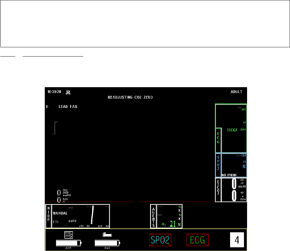
3-35
3.5.8 Oxygen Monitoring. This Parameter is part of the ETCO2/Agents module. That is, it uses
the exhaust air from the ETCO2/Agents module as its input and its air flow is controlled by the
pneumatic hardware in the ETCO2/Agents hardware module. The O2 value is displayed in the
Anesthetic Agents Display (See Figure 3-22).
Figure 3-22. Anesthetic Agents With O2 Displayed
a. Oxygen Module Calibration. The O2 Module is calibrated automatically upon
power-up (as described in the NOTE above). Thereafter, is calibrated every time
an O2 CAL is initiated by the user (See the GAS CAL Menu, SETUPS/
SERVICE(BIO-MED), GAS CAL for further information). The operator is
prompted that an O2 calibration is required if O2 remains above 22% for 12 hours
and, since O2 calibration requires one (1) minute, the operator may reject the
calibration request by answering NO to the YES/NO prompt. If NO is selected the
operator is then prompted every 30 minutes until the O2 calibration is initiated by
a YES response. Calibration is done based on the assumption that the ambient O2
concentration, sensed at the ETCO2 Zeroing Port, is 20.9% (during calibration, the
patient GAS Input Port must not be connected to an oxygen source).
MULTIPLE AGENTS Message flashes red with Alarm sound. Occurs
when more than one Anesthetic Agent is identified.
READJUSTING CO2
ZERO
Message flashing red. Occurs during CO2/
Anesthesia Gas Sensor zeroing operation.
REPLACE O2 SENSOR The life Oxygen Sensor has expired and must be
replaced.
NOTE
When the Agents parameter is turned on the O2 sensor is automatically calibrated
during initial warm up of the ETCO2/Agent Module. During this time the patient GAS
input port must not be connected to an oxygen source as the system requires 20.9%
Oxygen (room air) for automatic calibration.

3-36
b. Oxygen Sensor Replacement. The Oxygen Sensor (Invivo Part Number 9445) is
located on the rear of the WPU near the DCU mounting pole. The Oxygen Sensor
has an expected life of greater than six months with expected life inversely
proportional to changes in Oxygen Concentration, Temperature and Pressure. The
Oxygen Sensor begins aging immediately upon the opening of the package and
should, therefore, not be opened until ready for use. The Oxygen Sensor must be
replaced periodically as part of routine maintenance. The WPU cannot be
connected to the scavenge gas system without the Oxygen Sensor installed. Never
operate the Precess MRI Patient Monitoring System without the WPU connected
to the scavenge gas system. Always operate the WPU with the Oxygen Sensor
installed.
(1) Oxygen Sensor Replacement Instructions. Replace the Oxygen Sensor
as follows:
(a) Unplug the adapter cable from the Oxygen Sensor.
(b) Unscrew the Oxygen Sensor by turning it counterclockwise until it
comes free.
(c) Open bag containing new disposable Oxygen Sensor (Invivo part
number 9445).
(d) Screw Oxygen Sensor into threaded port on Adaptor Subassembly.
(e) Plug adapter cable assembly into the Oxygen Sensor.
3.6 Invasive Pressure Monitoring. The Precess MRI Patient Monitoring System provides up
to two invasive pressure channels, P1 and P2. Most invasive pressure monitoring functions are
contained in two primary menus: P1 and P2 (if the operator has selected labels for these, the menu
name will be the selected Label). These menus are brought up by selecting the corresponding
Menu-Select Icons.
There are three secondary menus (RECORD, ALARMS and Trends) associated with invasive
pressure monitoring:
•RECORDER Menu. Used to select all Recorder functions and to set the Recorder
and Trace Speed.
•ALARMS Menu. Used to Set and/or Disable the Pressure Alarms. The range of
Alarm Limits for the Pressure Channels is -10 to 249 mmHg.
•INVASIVE PRESSURE TREND Menu. Used to Setup and Print Trended
information.
3.6.1 Invasive Pressure Transducer Preparation. This system is designed for compatibility with
standard pressure transducers having a 5 µV/V/mmHg sensitivity. The transducer cable
connection is a six pin connector. Perform the following to use the Pressure Transducer:
a. Insert the Transducer connector cable into the appropriate Invasive Pressure
Connector (P1 and P2) on the PCU front panel.
b. Connect the patient end of the Pressure Transducer according to the transducer
manufacturer's instructions.
NOTE
Follow the instructions included in the Invasive Pressure Transducer Kit.
CAUTION
Reference the precautions included with the Invasive Pressure Transducer Kit.
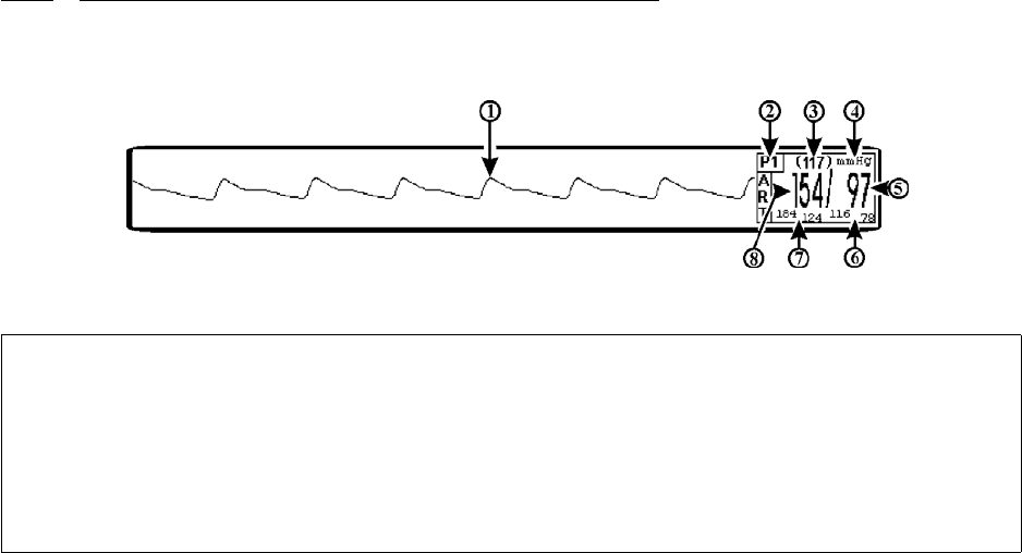
3-37
c. Vent the Transducer to atmospheric pressure as detailed in the Pressure Monitoring
Kit manufacturer’s instructions.
d. Press the ZERO ALL Control Key.
e. After successful Zeroing, close the Transducer's stopcock as described in the kit
instructions.
3.6.2 Associated Invasive Pressure Waveforms and Displays. (See Figure 3-23.) Invasive
Pressure information is displayed as a waveform in Trace locations E and F and as numeric data in
Boxes 5 and 6. The following is a description of the items contained within the Invasive Pressure
Display.
Figure 3-23. Invasive Pressure Display
a. Invasive Pressure Waveform. (Item 1) The Invasive Pressure Waveform is
displayed in Trace locations E (P1) and F (P2) as selected by the operator.
b. Icon Label. (Item 2) This label identifies the parameter numerics that are
displayed within this box. Invasive Pressure is monitored using boxes 5 and 6.
c. Mean Numeric. (Item 3) A numeric indication of the patient's Invasive Pressure
Mean reading.
d. Unit of Measurement. (Item 4) Displays the Unit of Measurement being used for
presentation of the numeric data.
e. Diastolic Numeric. (Item 5) A numeric indication of the patient's Invasive
Pressure Diastolic reading.
f. Diastolic Alarm Limits. (Item 6) A numeric indication of the settings of the High
(on top in the example) and Low (bottom in the example) Diastolic Alarm Limits.
g. Systolic Alarm Limits. (Item 7) A numeric indication of the settings of the High
(on top in the example) and Low (bottom in the example) Systolic Alarm Limits.
h. Systolic Numeric. (Item 8) A numeric indication of the patient's Invasive Pressure
Systolic reading.
NOTE
If the Transducer will not zero and an error condition occurs, check that the Transducer
is being used as described in the Invasive Pressure Transducer Kit instructions. Select
the RETRY button (on the monitor display screen) to attempt to zero the Transducer
again. If the Transducer still does not zero, try another transducer and/or cable. If
condition still does not clear, contact Invivo Service Department or authorized Invivo
Service Personnel.
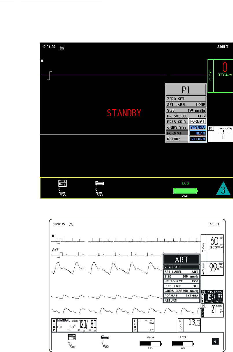
3-38
3.6.3 The Invasive Pressure Menu. Selecting the P1 Menu-Select Icon will bring up the P1
Menu (See Figure 3-24). The title of this menu is dependent upon the operator selected Label for
P1; if “NONE” is selected the title will be P1; if any other available Label is selected the title will
be the selected Label (for example, the label ART is selected in Figure 3-25 and the menu title is
ART). This menu has a time-out feature. If no action is taken for approximately 60 seconds,
the display will automatically return to the Normal Screen.
Figure 3-24. P1 Menu Selection, MEAN Format
Figure 3-25. The P1 Menu (ART Selected)
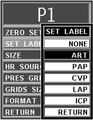
3-39
a. ZERO SET. Selecting this menu option zeros the Pressure Transducer for this
channel. The Transducer must be zeroed before each use and at regular intervals
during use. The Transducer must be vented to atmospheric pressure before the
ZERO-SET Menu Option is selected. On successful completion of zeroing, the
message “DONE” flashes under ZERO-SET on the menu.
b. SET LABEL. (See Figure 3-26.) Scrolls through a list of Labels to be put next to
the Mean Pressure numerics to help the user to identify the transducer site. The
options are ART, PAP, CVP, LAP, ICP, and NONE (default). The selected Label
not only becomes the Pressure Channel Menu Title, it determines the color of the
visual display. If NONE is selected, the Menu-Select Icon highlight is White; ART
is Pink, PAP is Yellow, CVP is Blue, LAP is Purple and ICP is Blue.
Figure 3-26. Invasive Pressure SET LABEL Menu
c. SIZE. Selecting this menu option sets the Scale of the Trace for this Pressure
Channel. The options are 40, 75, 100, 150, 200 (default), and 250 mmHg.
d. HR SOURCE. Selecting this menu option allows the selection of the Source to be
used for the Heart Rate display in TRACE A area. The options are AUTO, ECG
(default), ART (first encountered arterial pressure), SPO2 and NIBP.
(1) The Heart Rate is displayed in the ECG Parameter Box, and it is annotated
with its Source (e.g., “60 (P1/P2)” indicates a Heart Rate of 60, derived
from the Arterial Pressure).
(2) If AUTO is chosen, the Heart Rate is obtained automatically from the
highest priority active input. When set to AUTO, the system searches for
another Source for rate only when LEAD FAIL occurs or the ECG
Parameter is turned OFF. The priority, from highest to lowest, is ECG, P1,
P2, SpO2, and NIBP.
(3) The system examines the highest priority input for a Heart Rate. If not
found, it will go to the next highest priority Parameter and determine if a
valid Heart Rate is present. If none of the Parameters are presenting a Heart
Rate and NIBP is shut OFF, then “NONE” is displayed on the DCU in the
Heart Rate position.
This menu option is identical to, and interactive with, the similarly named
menu options under ECG, SPO2, and NIBP.
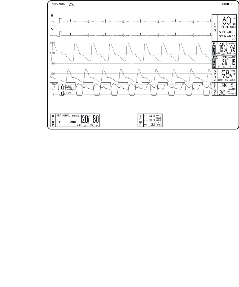
3-40
e. PRES GRID. Selecting this menu option selects the Pressure Grid. The options
are ON and OFF (default).
With this menu option set to ON, graticule lines appear on the screen, and numbers
indicating the values of these lines appear at the left-hand side of the lines (See
Figure 3-27). The Pressure Traces (shown with bold lines in Figure 3-27) align
themselves to their respective area of the grid so that they may be compared. This
menu option (and a similar one in the P2 Menu) may be set from any of the two
Pressure Channel Menus. It affects only the pressure channels that are assigned to
a display Trace C through F).
Figure 3-27. Full Screen Display of Invasive Pressures with Graticule Lines
f. GRIDS SIZE. This menu option is active (its Label displayed) only if PRES
GRID is not set to OFF (see above). Selecting it will change the Scale of the
Trace(s) for full-screen viewing. The options are 40, 75, 100, 150 (default),
200 and 240 mmHg.
g. FORMAT. Selecting this menu option allows the operator to change the Display
format of the Pressure numerics. If SYS/DIA is selected, the Systolic and Diastolic
numerics will be in a large font separated by a “slash” and the Mean numeric will
be in a smaller font bracketed with parenthesis. If MEAN is selected, the Mean
numeric is displayed in the large font with the Systolic and Diastolic numerics
separated by a “slash” in a smaller font. For Pressure Labels that designate only a
single Pressure (e.g., CVP and ICP), the mode is automatically changed to the
Mean Format and the operator is informed that the Format cannot be changed for
the current Label if a change to the Sys/Dia Format is attempted.
h. RETURN. Selecting this menu option will return the display to the Pressure
Menu.
The operation and menus of P2 are identical to the operation of P1 as described above.
3.6.4 Invasive Pressure Alarm Limits. Alarm Limits may be set two ways. To set the Alarm
Limits for every available Parameter, press the ALARMS SCREEN Menu-Select Key to access
the ALARMS Menu. To set the Alarm Limits for any Invasive Pressure only, highlight the
Invasive Pressure Icon and press the ALARMS SCREEN Menu-Select Key to access the
individual Parameter Alarm Limits Box. The range of Alarm Limits for the Pressure Channels is -
10 to 249 mmHg.

3-41
3.6.5 Invasive Pressure Trended Data. For complete information on the Trending of patient
Invasive Pressure data, see Section 5, Recording and Trending.
3.6.6 Invasive Pressure Messages. The following is a list of messages that may be displayed
during Invasive Pressure monitoring:
3.7 Temperature Monitoring. The Temperature Menu (TEMP) is brought up (if this
Parameter is turned on through the Setups Menu) with the TEMP Menu-Select Icon. The Precess
MRI Patient Monitoring System is configured with one Temperature Channel for use with fiber
optic temperature probes or sensors. Temperature values are displayed in °C or °F (as selected by
the operator)..
The following three secondary menus support the Temperature monitoring feature:
•RECORDER Menu. Used to select Recorder functions and to set the Recorder
and Trace Speed.
•ALARMS Menu. Used to Set and/or Disable the Temperature Alarms. The range
of Alarm Limits for Temperature is 20.0 to 44.0°C or 68.0 to 111.2°F.
•TEMPERATURE TREND Menu. Used to Setup and Print Trended information.
3.7.1 Associated Temperature Displays. (See Figure 3-28.) Temperature information can only
be displayed as numeric data. Temperature is shown in Box 10. The following is a description of
the items contained within the Temperature Display.
ERR:LO-RANGE Displayed during ZEROING of the transducer if the offset is too
low to be zeroed.
ERR:HI-RANGE Displayed during ZEROING of the transducer if the offset is too
high to be zeroed.
ERR:UNSTABLE Appears below ZERO-SET if the transducer is not within the
stability range. This indicates that the transducer is picking up
some vibration, possibly caused by incomplete closure of a
patient's stopcock.
NOTE
The thermometer portion of this equipment conforms to all of the requirements
established in ASTM Standard E1112:00.
The accuracy of the thermometer portion of this equipment can be verified by
exceeding alarms limits using a temperature bath.
Equipment performance will be degraded when receiving a mechanical shock greater
than 15G (peak), with a nominal velocity change of 40.56 inches/second.
NOTE
The minimum measuring time to obtain accurate readings at a specific body site is
57 seconds.
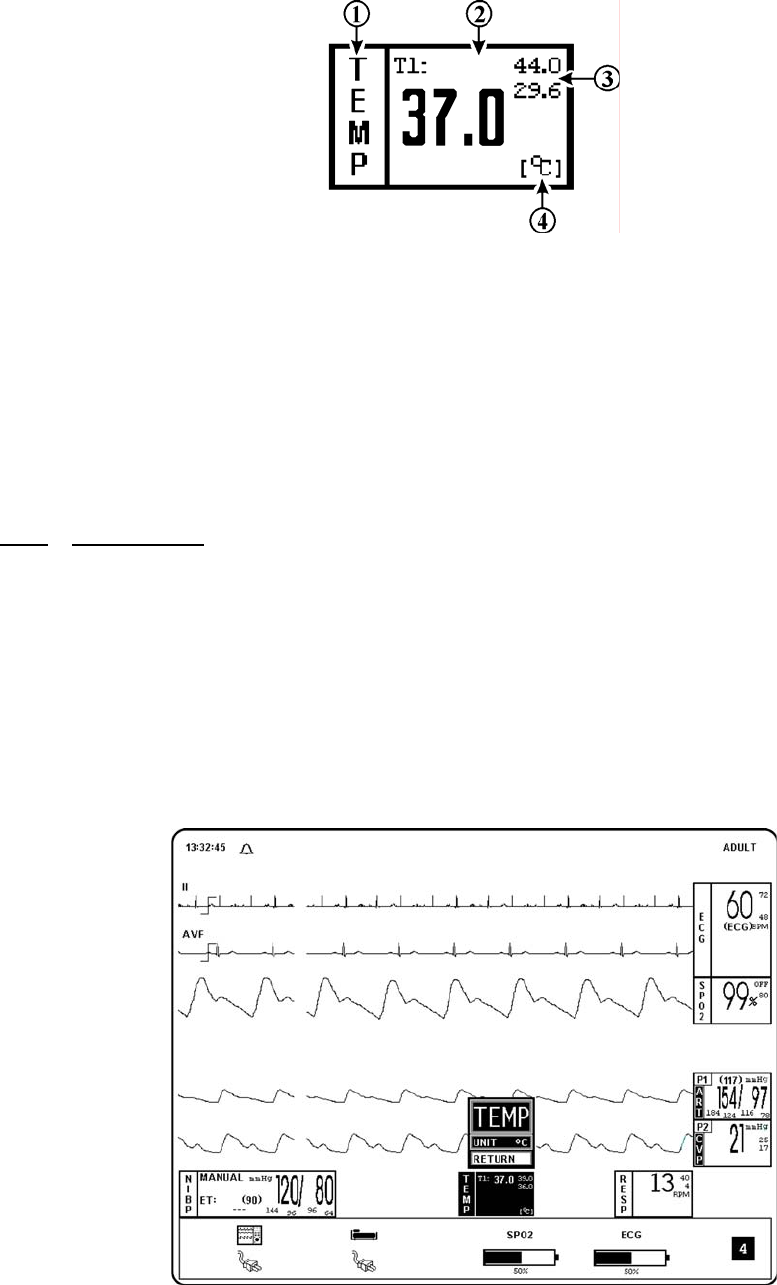
3-42
Figure 3-28. The Temperature Display
a. Icon Label. (Item 1) This label identifies the parameter whose numeric data is
being displayed within the Icon Box.
b. Temperature Numeric. (Item 2) A numeric indication of the patient's
Temperature reading.
c. Alarm Limits. (Item 3) A numeric indication of the settings of the High (on top in
the example) and Low (bottom in the example) Temperature Alarm Limits.
d. Unit of Measurement. (Item 4) Displays the Unit of Measurement being used for
presentation of the numeric data.
3.7.2 TEMP Menu. (See Figure 3-29.) The TEMP Menu for the Temperature Channel is
brought up by selecting the TEMPERATURE Menu-Select Icon. The values for this Parameter
are indicated in the Vital Signs Display on the bottom of the Normal Screen.
Temperature is displayed in °F or °C, as selected in the TEMP Menu. The Temperature display
may be turned OFF and ON from the Parameter Selection Menu. This menu has a time-out
feature. If no action is taken for approximately 60 seconds, the display will automatically
return to the Normal Screen.
If the Temperature detected by the system is under the lower limit (or if the probe/sensor is
disconnected or faulty), the message “UND” appears in the Temperature display area. If the
Temperature detected by the system is over the upper limit (or if the probe/sensor is faulty), the
message “OVR” will appear in the Temperature display area.
Figure 3-29. The TEMP Menu
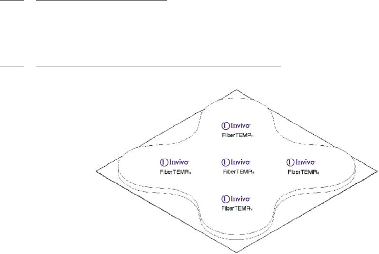
3-43
The following is a description of the options provided in the TEMP Menu:
a. UNIT. Selecting this menu option switches the unit for the Temperature display
between °F and °C (default).
b. RETURN. Selecting this menu option will return the display to the Normal Screen
3.7.3 Temperature Alarm Limits. Alarm Limits may be set two ways. To set the Alarm Limits
for every available Parameter, press the ALARMS SCREEN Menu-Select Key to access the
ALARMS Menu. To set the Alarm Limits for Temperature only, highlight the Temperature Icon
and press the ALARMS SCREEN Menu-Select Key to access the individual Parameter Alarm
Limits Box. The range of Alarm Limits for temperature is 20.0 to 44.0°C or 68.0 to 111.2°F.
3.7.4 Using the Fiber-Optic Surface Temperature Sensor. (See Figure 3-30.) Prior to use, refer
to the instruction accompanying the Fiber-Optic Surface Temperature Sensor:
Figure 3-30. FiberTEMP Surface Applicator
a. Fiber-Optic Surface Temperature Sensor Precautions. The following
Precautions apply to the use of the Fiber-Optic Surface Temperature Sensor:
• This sensor contains fiber-optic material. It must be handled with care.
• Do not bend fiber-optic sensor cable in a radius of less than 0.5 inches
(13 mm).
• Sensor can be damaged if handled with excessive force.
• Do not pull on fiber-optic sensor cable or place it under tension.
• Do not allow cable to become tangled.
• Failure to properly apply sensor will cause incorrect measurements.
• The Invivo Part Number 9320 sensor is designed only to measure patient
surface temperature. Do not insert this sensor into any patient body orifice.
• Do not alter or modify sensor in any way. Alterations or modifications will
affect performance, accuracy and will void warranty.
• Do not autoclave sensor for sterilization. Sensor damage will result.
• Do not immerse the complete sensor in any type of liquid. Sensor damage
will result.
• Replace the protector cap on the sensor connector when the sensor is not in
use.

3-44
b. Cleaning the Fiber-Optic Surface Temperature Sensor. Never immerse the
complete sensor into liquid. Clean the Fiber-Optic Surface Temperature Sensor
after each patient use. This sensor must be cleaned with isopropyl alcohol or mild
soap and water. Disinfect sensor with 70% isopropyl alcohol or sodium
hypochlorite (bleach diluted 1:10 minimum with water). Ethylene oxide gas
sterilization is the preferred sterilization method.
c. FiberTEMP™ Sensor Application Instructions. Perform the following
procedure to apply the Fiber-Optic Surface Temperature Sensor to a patient:
(1) Before each use, carefully inspect the FiberTEMP reusable Fiber-optic
surface temperature sensor (Invivo Part Number 9320) for damage.
(2) Use only FiberTEMP Sensor Applicators (Invivo Part Number 9321, See
Figure 3-30) to apply this sensor to the patient. Applying the sensor to the
patient with tape will damage sensor and thus void sensor warranty.
(3) Determine the site where temperature is to be monitored (i.e. under the
arm). Clean application site thoroughly.
(4) Remove backing from FiberTEMP Surface Applicator to expose adhesive
contact area.
(5) Position sensor paddle at the application site and place FiberTEMP Sensor
Applicator over the sensor paddle (See Figure 3-30).
(6) Allow time for the temperature to stabilize.
3.7.5 Temperature Trended Data. For complete information on the Trending of patient
Temperature data, see Section 5, Recording and Trending.
3.7.6 Temperature Messages. The following is a list of messages that may be displayed during
Temperature monitoring:
WARNING
During long term monitoring sessions (4 hours or more), frequent medical
attention must be given to sensor site for possible pressure tissue necrosis,
especially on tender skin of neonatal patients.
NOTE
There is a temperature difference between patient surface temperature and patient
body temperature.
During MRI procedures a large amount of radio frequency (RF) energy is present and
this RF energy will cause the patient’s body temperature to increase.
UND The temperature has fallen below 20.0qC (69.8qF) or probe and/
or temperature module has become inoperative. If this message
is seen with multiple probes, re-start the WPU. If this doesn’t
correct the problem, refer the Precess MRI Patient Monitoring
System to qualified service personnel.
OVR The temperature has risen above 44.0qC (111.2qF).
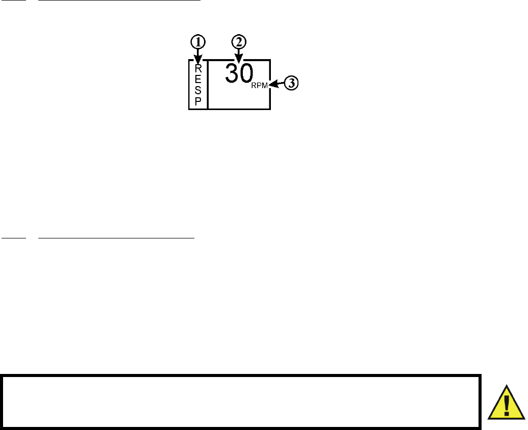
3-45
3.8 Respiration Monitoring. Respiration is monitored by detecting the patient’s abdominal
or chest wall motion through a pneumatic bellows placed at the patient’s chest. There are no user
adjustable options for this Parameter.
3.8.1 Associated Respiration Displays. (See Figure 3-31.) Respiration information can only be
displayed as numeric data. The following is a description of the items contained within the
Respiration Display.
Figure 3-31. The Respiration Display
a. Icon Label. (Item 1) This label identifies the parameter whose numeric data is
being displayed within the Icon Box.
b. Temperature Numeric. (Item 2) A numeric indication of the patient's Respiration
reading.
c. Unit of Measurement. (Item 3) Displays the Unit of Measurement being used for
presentation of the numeric data.
3.8.2 Respiration Patient Preparation. Respiration is determined using a Bellows method
making chest wall expansion very important for accurate measurement. If the respiratory signal
appears to weaken, instruct the patient (between scans) to breathe more deeply during the scan
(thus creating more movement at the sensor site).
To position the respiratory sensor, perform the following:
a. Place the sensor on the patient’s upper abdomen or lower chest (whichever
expands most during inspiration and preferably the area to be scanned).
b. Use a Velcro strap (hip/shoulder strap) to secure the sensor in place.
c. Connect the flexible tube to the sensor.
d. Gently push and twist the flexible tube connector a quarter turn clockwise onto the
appropriate socket.
e. Check the respiratory signal before the patient is placed in the magnet.
f. Position the patient in the magnet. Ensure that the flexible tube does not get caught
(e.g.: between the tabletop and patient support).
WARNING
Avoid excessive bending of the flexible tube as this will impair detection of the
patient’s respiration.

4-1
SECTION 4
PREPARATION FOR USE
4.0 PREPARATION FOR USE.
4.1 Introduction.This system provides the operator with the ability to store and recall
different system configurations, select and display the available parameters, select special system
functions, set the date and time and select test menus. Access to this wide array of features is
available through the Setups Menu which is accessed by pressing the SETUP Menu-Select Key.
4.2 Setups Menu. (See Figure 4-1.) On the DCU, pressing the SETUP Menu-Select key
brings up the SETUPS Menu. From this menu, the operator has the ability to fine tune the
operation of the Precess MRI Patient Monitoring System to suit individual situations.
4.2.1 DCU Setups Menu. While in the Setups Menu, individual Setup configurations may be
Saved and Recalled, the available Parameters may be turned Off and On, the DCU Sounds may be
adjusted, the patient mode may be switched between Adult and Neonate, the Pediatric ECG mode
may be turned On and Off (while in ADULT patient type only - with NEO patient type it is always
On), the Date and Time may be adjusted, the Network designation may be set, and the system
may be set to default to the Factory or a User configuration. In addition to control over these
features, this menu allows the Sweep Speed and Respiration Speed to be selected. This menu has
a time-out feature. If no action is taken for approximately 60 seconds, the display will
automatically return to the Normal Screen.
CAUTION
Prior to clinical use, the operator must be aware of the minimum distance from the
MRI System for proper operation.
NOTE
If a particular parameter is not installed, it can not be set to ON. Once the system is
configured for a particular procedure or user, the store and recall feature can be used
to instantly reset the monitor.
The SETUPS Menu is different from the Display Controller Unit (DCU) to WPU due to
the different operational requirements of the separate units that comprise the Precess
MRI Patient Monitoring System. Paragraph 3.2 will first discuss what is common
between the two then divide into unique sections to cover the differences between the
DCU and WPU Setups Menu.
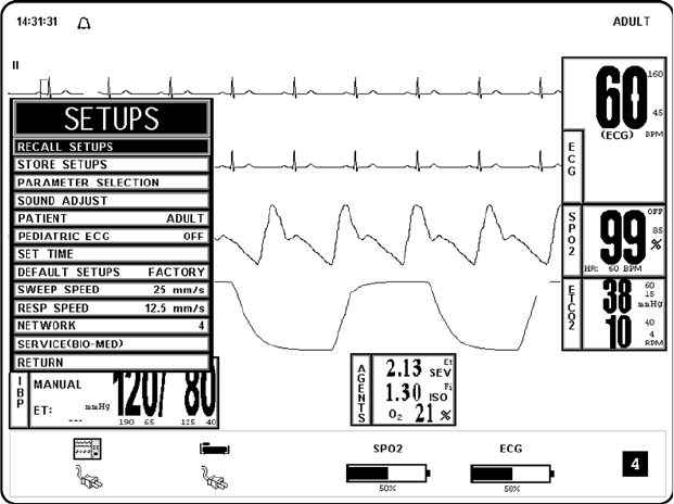
4-2
Figure 4-1. The DCU SETUPS Menu
When the second DCU is used in the Precess MRI Monitoring System, commands which control
the system patient parameters functions (i.e. ECG, NIBP, P1, P2, SpO2, ETCO2, Agent Analysis,
Temperature, Respiration, and Alarms) are synchronized between the two DCUs via the WPU.
Commands that do not directly control patient parameters (i.e. Recorder functions) will only
affect the individual DCU where the command was initiated. The following list defines the
settings that are not synchronized between DCUs.
• Alarm Volume
• Pulse Volume
• Click Tone
• Click Volume
• Time Of Day
• Alarm Silence/Hold Condition
• Network Settings
• Recorder Configuration
• Data Logging Interval
• Trace Sweep Speed
• Trend Data
• Trend Configuration
• Blood Pressure Display Format
• ETCO2 Grids
• System Configuration Recorder Setting
• System Configuration Analog Output Setting
• System Configuration Line Frequency Setting
• System Configuration Language Setting
When two DCUs are used with the system, information is exchanged between them by
communicating through the WPU unit. Thus, when the WPU unit is turned OFF, no information is
exchanged between the two DCUs, and any changes to the various parameter, alarm, and other
settings that are made will only affect the DCU upon which those changes are made.

4-3
In a scenario where the WPU and one DCU unit is turned ON and the two units are
communicating, the second DCU, when it is turned ON, will “inherit” the settings from the first
DCU. In other words, the settings from the already ON DCU will be communicated (via the
WPU) to the second DCU that has been turned ON.
In the scenario where both DCUs are already turned ON, but the WPU is OFF, when the WPU is
turned ON, it will acquire the settings from the first DCU it establishes communication with, and
then will relay these settings to the remaining DCU.
4.2.2 Store/Recall Setups. The Precess MRI Patient Monitoring System has seven (7) memory
blocks, each of which has enough capacity for the current setting of every control Setup, Alarm
Limits, Trend Time Base, etc. on the monitor. The operator is able to Store and Recall seven
different configurations of the system. The seventh (USER DEFAULTS) is also used for Recall at
system power up. The memory blocks are maintained by a long life battery, or static RAM
memory, which will keep the memory contents intact even when power is off.
Settings for the system can be stored for different procedures, different types of patients, etc., or
multiple users of the system can Store and Recall their own preferred configurations without
having to individually set each limit, status, etc., before each use.
Each storage memory block maintains the settings for the following:
a. ALARMS. The setting of MIN and MAX values, Auto-set percentage, Latched or
Unlatched selection for Alarms, and Alarm Tone Enabled/Disabled.
b. SYSTEM SETUPS. All Settings.
c. ECG. Selected Lead, Scale setting, Trace Speed, Filter Mode, QRS Tone On/Off
and Heart Rate Source.
d. RECORDER. Off or Auto, Trace Delay, Recorder Speed and the selected Traces.
e. NIBP. Manual, Off or Auto and the Automatic Time Interval.
f. ETCO2. Size, Grids and Flow.
g. TREND GRAPHS. Time Bases and Scales.
h. SpO2. Size.
Once the system is setup properly, the Setups may be Stored in one of the available memory
blocks. The Stored Setups can be brought up via the Recall Setups Menu.
The following is a description of the operation of the DCU Setups Menu Options:
a. DCU Recall Setups. To select this menu option, turn the Rotary Knob until the
RECALL SETUPS Option is highlighted, then press the Rotary Knob to select.
Selecting this menu option will bring up the RECALL SETUPS Submenu and
allow the operator to Recall a previously stored Monitor Setup (See Figure 4-2).
NOTE
In various menus, the operator may accidentally make a selection that has significant
irreversible effects (e.g.: erasing patient data). To protect against such accidents a
Yes/No Menu is associated with these selections. This menu has only two active
selections: YES and NO. The operator must select one of the two choices to either
confirm the change to take place, or to cancel it. A delay of approximately 30 seconds
without any selection is equivalent to selecting NO. The Yes/No Menu is removed
upon operator selection, at the end of the time-out feature, by pressing the NORMAL
SCREEN button or by pressing the STANDBY button.
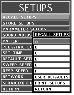
4-4
Figure 4-2. The DCU RECALL SETUPS Menu
The following is a description of the RECALL SETUPS Menu Options:
(1) A. To select this menu option, turn the Rotary Knob until A is highlighted,
then press the Rotary Knob to select. Selecting this menu option brings up
a YES/NO Confirmation Menu and, upon confirmation, will Recall the
Setups for the monitor from the Memory Block A.
(2) B. Except for using the Memory Block B, this menu option is identical in
function to Menu Option A.
(3) C. Except for using the Memory Block C, this menu option is identical in
function to Menu Option A.
(4) D. Except for using the Memory Block D, this menu option is identical in
function to Menu Option A.
(5) E. Except for using the Memory Block E, this menu option is identical in
function to Menu Option A.
(6) F. Except for using the Memory Block F, this menu option is identical in
function to Menu Option A.
(7) USER DEFAULTS. Selecting this menu option recalls the Setups for the
system from the USER DEFAULTS memory block. If no User Defaults
have been set, this selection will Recall the Factory Defaults.
If the DEFAULT SETUPS is set to USER in the Setups Menu, the monitor
will automatically Recall the Setups stored in this memory block for New
Patients upon system power-up.
(8) PRINT SETUPS. To select this menu option, turn the Rotary Knob until
PRINT SETUPS is highlighted, then press the Rotary Knob to select.
Selecting this menu option brings up the Print Setups Menu, which
provides a selection of system setups to print.
(9) RETURN. Selecting this menu option returns the monitor to the Normal
Screen.
b. DCU Store Setups. To select this menu option, turn the Rotary Knob until the
STORE SETUPS Option is highlighted, then press the Rotary Knob to select.
Selecting this menu option will bring up the Store Setups Menu and allow the
operator to Store up to seven (7) sets of Monitor Setups for future Recall (See
Figure 4-3).
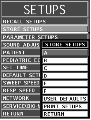
4-5
Figure 4-3. The DCU STORE SETUPS Menu
The following is a description of the STORE SETUPS Menu options:
(1) A. Selecting this menu option will store all setups for the system in the
storage Memory Block A.
(2) B. Except for using the Memory Block B, this menu option is identical in
function to Menu Option A.
(3) C. Except for using the Memory Block C, this menu option is identical in
function to Menu Option A.
(4) D. Except for using the Memory Block D, this menu option is identical in
function to Menu Option A.
(5) E. Except for using the Memory Block E, this menu option is identical in
function to Menu Option A.
(6) F. Except for using the Memory Block F, this menu option is identical in
function to Menu Option A.
(7) USER DEFAULTS. Selecting this menu option will Store all Setups for
the system in the User Defaults Storage Memory Block.
If the DEFAULT SETUPS is set to USER in the Setups Menu, the system
will automatically Recall the Setups stored by this menu option.
(8) PRINT SETUPS. Selecting this menu option brings up the Print Setups
Menu which provides a selection of system setups to Print.
(9) RETURN. Selecting this menu option returns the display to the Normal
Screen.
c. DCU Parameter Selection. To select this menu option, turn the Rotary Knob until
the PARAMETER SELECTION Option is highlighted, then press the Rotary
Knob to select. Selecting this menu option will bring up the Parameter Selection
Menu (See Figure 4-4).
Selection of this menu allows the operator to turn various Parameters ON and OFF.
If the Parameter selected is not installed, attempting to turn it ON will cause the
message “XXX IS NOT ENABLED” to be displayed. If the FREEZE feature is
Enabled, changes to Parameter Selections are not allowed; if FREEZE is Enabled,
the DCU displays a WARNING Box that alerts the operator that this menu may not
be accessed.
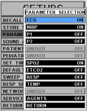
4-6
Figure 4-4. The DCU PARAMETER SELECTION Menu
The following is a description of the PARAMETERS SELECTION Menu
Options:
(1) ECG. Selecting this menu option will turn the ECG display ON (default) or
OFF. The Heart Rate will remain on the screen, allowing it to be displayed
from another Source if the Heart Rate Source (the HR SOURCE selection)
is set to AUTO.
(2) NIBP. Selecting this menu option switches the NIBP ON (default) and
OFF.
(3) P1. Selecting this menu option switches P1 ON and OFF.
(4) P2. Selecting this menu option switches P2 ON and OFF.
(5) SPO2. Selecting this menu option switches SpO2 ON and OFF.
(6) ETCO2. Selecting this menu option switches ETCO2 ON and OFF.
(1) RESP. Selecting this menu option switches Bellows Respiration ON and
OFF. Note: Bellows Respiration has no waveform.
(2) TEMP. Selecting this menu option switches Temperature ON and OFF.
(3) AGENTS. (If option is installed) Selecting this menu option switches the
Anesthetic Agent Option ON and OFF (default).
(4) RETURN. Selecting this menu option returns the display to the Normal
Screen.
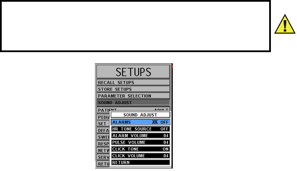
4-7
d. DCU Sound Adjust. Selecting this menu option will bring up the SOUND
ADJUST Menu (See Figure 4-5) which allows the user to switch the Alarm Tone
ON and OFF, set the Heart Rate Tone Source and set the Volume for the different
sounds the Precess MRI Patient Monitoring System produces. While in this menu,
all real tones are Disabled and the message “REAL TONES DISABLED” is
displayed at the top of the screen. Note that only the sound is Disabled and the
violated Alarms will still flash in RED on the screen if the Parameter's Alarm Limit
is violated.
Figure 4-5. The DCU SOUND ADJUST Menu
The following is a description of the DCU SOUND ADJUST Menu Options:
(1) ALARMS. Selecting this menu option will turn the alarm sound ON and
OFF. When turned OFF, an “X” appears in the Bell symbol on the screen
and in the menu option area, indicating that the alarm sound has been
Disabled. This menu option is identical to, and interactive with, the
SOUND Menu Option in the Alarms Menu.
(2) HR TONE SOURCE. Selecting this menu option will select the Heart
Rate Tone Source. The options are OFF (default), QRS and SPO2. When
Source is QRS, the Tone sounds at the detection of QRS from the ECG
Parameter. When Source is SpO2, the Tone sounds at the detection of the
pulse from the Pulse Oximeter parameter.
When Source is set for SpO2, the pulse tone is modulated by the SpO2
value. The lower the SpO2 value, the lower the pitch will be of the Pulse
Tone.
This menu option is identical to, and interactive with, the HR Tone Source
Menu option in the ECG and SPO2 Menus.
WARNING
The Alarm Tone can be set to OFF. Always check that the Alarm Tone setting is
appropriate for each particular patient. Alarm Sound volume is adjustable for
suitability to various clinical environments (where background noise may range
from relatively quiet to noisy). Always verify that the clinician using this system
can hear the Alarm Sound above the ambient noise.
4-8
(3) ALARM VOLUME. Selecting this menu option allows the selection of
volume for the Alarm Tone. The range is 1 - 10 (default is 4).
The Precess MRI Patient Monitoring System generates the Alarm Tone
(while in the VOLUME Menu) to provide the user with an audible
indication of the current Volume Level setting.
(4) PULSE VOLUME. Selecting this menu option allows the selection of
volume for the Pulse Tone. The range is 1 - 10 (default is 4).
The Precess MRI Patient Monitoring System generates the Pulse Tone
(while in the VOLUME Menu) to provide the user with an audible
indication of the current Volume Level setting.
(5) CLICK TONE. Selecting this menu option turns the Click Tone
generation of the device ON and OFF without affecting the adjusted
volume for the Click Tone.
The Precess MRI Patient Monitor generates the Click Tone (while in the
VOLUME Menu) to provide the user with an audible indication of the
current Volume Level Setting.
(6) CLICK VOLUME. Selecting this menu option allows the selection of
Volume for the Click Tone. The range is 1 - 10 (default is 4).
(7) RETURN. Selecting this menu option returns the display to the Normal
Screen.
e. DCU Patient. Selecting this menu option determines the ADULT (default) or the
NEONATE Mode for the operation of the ECG and NIBP parameters.
(1) ADULT. The initial NIBP inflation pressure is 170 mmHg. The maximum
inflation pressure is 285 mmHg. Also, the adult NIBP pre-amplifier and the
adult NIBP algorithm are used. ECG Heart Rate detection sensitivity is
200 µV minimum.
(2) NEONATE. The initial inflation pressure is 120 mmHg. The maximum
inflation pressure is 150 mmHg. Also, the neonatal NIBP pre-amplifier and
the neonatal NIBP algorithm are used. ECG Heart Rate detection
sensitivity is 100 µV minimum.
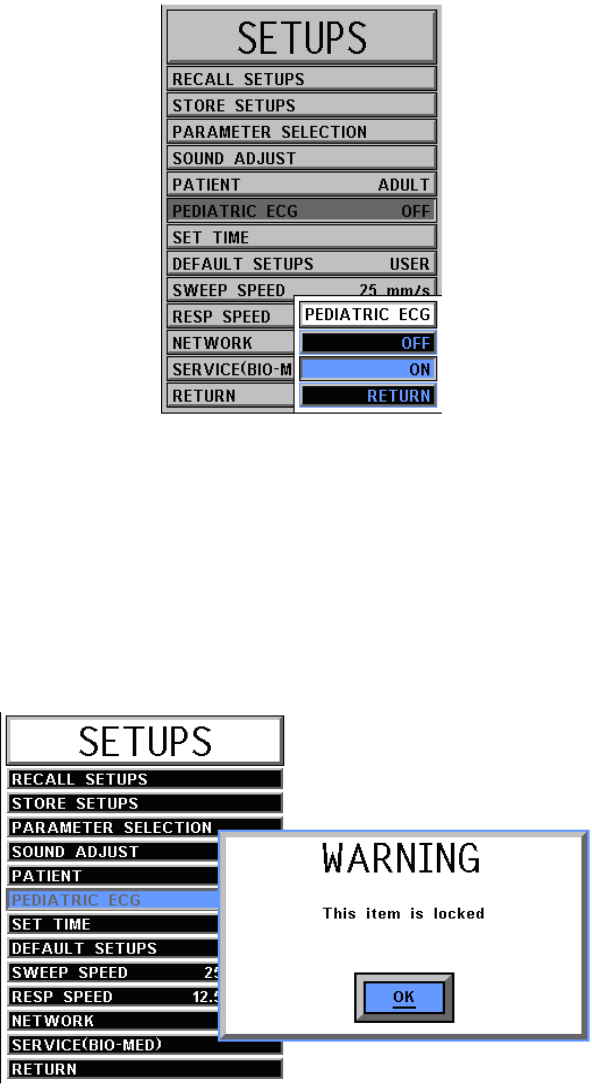
4-9
f. Pediatric ECG. Selecting this menu option provides additional ECG filtering
when patients, particularly pediatric patients, present with a narrow QRS complex
and/or high heart rates. This menu item will have 2 options: OFF or ON. The
factory default setting will be OFF.
Figure 4-6. The Pediatric ECG Menu
(1) When PEDIATRIC ECG is set to ON, the ECG data is processed with a
pediatric algorithm in addition to the current MRI gradient filter setting.
(2) Whenever the NEO patient type is selected, the PEDIATRIC ECG item
will be automatically set to ON. This also means that whenever the patient
type is set to NEO, the PEDIATRIC ECG item will be “locked” to the ON
position and the user will not be allowed to change its setting to OFF from
ON. Upon transition from the NEO patient type to the ADULT patient
type, the PEDIATRIC ECG item will be automatically set to OFF.
Figure 4-7. Pediatric ECG “Locked” Warning
(3) When an ECG trace is printed, the following will appear in the annotation
strip following the ECG filter indication: “PED ECG=ON” (if this item is
ON), “PED ECG=OFF” (if this item is OFF).
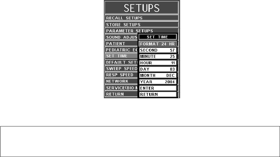
4-10
(4) The setting of the PEDIATRIC ECG item will be stored in the user settings
(A through F or USER) when the user stores the system settings. The
setting of this item will also be recalled from one of the stored settings
when the user performs a “settings recall” or if the system is booted from
USER. The factory default setting is OFF.
(5) The current setting of the PEDIATRIC ECG item will be synchronized
among DCUs.
g. Set Time. Selecting this menu option will bring up the SET TIME Menu (See
Figure 4-8). From the SET TIME Menu the Time and Date may be set. The Time
is displayed in the upper left corner of the display. The clock continues to operate
when the power is off. The Date format is MMM DD, YYYY (e.g., Jan. 01, 2001).
Figure 4-8. The DCU SET TIME Menu
The following is a description of the operation of the SET TIME Menu options:
(1) FORMAT. Selecting this menu option switches the Format of the time
display between 12 hour and 24 hour.
(2) SECOND. Selecting this menu option allows scrolling through Seconds.
(3) MINUTE. Selecting this menu option allows scrolling through Minutes.
(4) HOUR. Selecting this menu option allows scrolling through Hours.
(5) DAY. Selecting this menu option allows scrolling through Days.
(6) MONTH. Selecting this menu option allows scrolling through Months.
(7) YEAR. Selecting this menu option allows scrolling through Years.
(8) ENTER. Selecting this menu option enters the newly selected Time and
Date when all changes are completed.
Pressing ENTER after the new Time and Date are completely set puts the
newly set Time and Date into effect. Otherwise, the old time is restored
upon exiting the SET TIME Menu.
(9) RETURN. Selecting this menu options returns the display to the Normal
Screen.
NOTE
No new window is provided for the following selections. The setting to be adjusted
becomes highlighted within the existing menu.
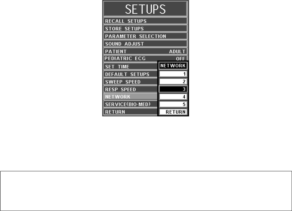
4-11
h. Default Setups. Selecting this menu option will switch the power-on Defaults
between FACTORY and USER Modes. If set to FACTORY, the system will power
up with the entire system reset to Factory Default values. If set to USER, the
system will power up and automatically Recall the User Defaults from memory.
i. Sweep Speed. Selecting this menu option will bring up the SWEEP SPEED Menu.
The Sweep Speed Menu allows the operator to switch the Recorder and the display
Trace Speed between 25 and 50 mm/second. This menu option is identical to, and
interactive with, the Sweep Speed Menu Option in Recorder Menu.
j. Respiration Speed. Selecting this menu option will bring up the RESP SPEED
Menu. The Resp Speed Menu allows the operator to set the Respiration Speed at
the following predetermined levels: 25 mm/s, 12.5 mm/s, 6.25 mm/s, 3.125 mm/s,
1.5625 mm/s and 0.33333 mm/s.
k. Network. Selecting this menu option brings up the NETWORK Menu. The
Network Menu (See Figure 4-9) allows the operator to set the Network
designation of the DCU. This designation must match between the DCU and WPU
for the two units to communicate.
Figure 4-9. DCU NETWORK Menu
l. Service (Bio-Med). Selecting this menu option will bring up the SERVICE (BIO-
MED) Menu (See Figure 4-10). The SERVICE (BIO-MED) Menu provides the
operator with the ability to identify the Software Revision level, place the system
into a Simulation Mode (used for training purposes only) and review the
configuration of the system.
NOTE
The SERVICE (BIO-MED) Menu must only be used by qualified service personnel
thoroughly familiar with the operation and service of the Precess MRI Monitoring
System. See Service Manual Part Number 9568.
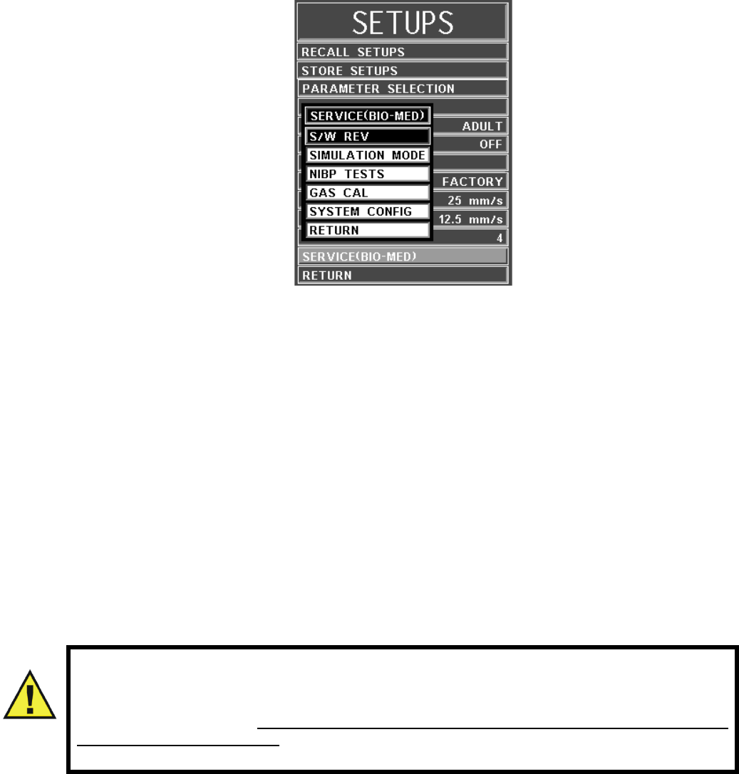
4-12
Figure 4-10. The DCU SERVICE (BIO-MED) Menu
The following is a description of the options available in the SERVICE
(BIO-MED) Menu:
(1) S/W REV. Selecting this menu item brings up another window which
contains detailed information about the operating software of the DCU.
This window contains the revision level and date of build along with other
technical information concerning the DCU software. To exit this window,
the operator either selects the OK button on the window or the NORMAL
SCREEN Key on the DCU front panel.
(2) SIMULATION MODE. This menu option allows the operator to turn the
Simulation Mode ON. When selected, the display will first display a YES/
NO Menu and require user confirmation before entering the Simulation
Mode. While in the Simulation Mode, the displayed patient information is
computer generated and not actual patient determinations. As a safety
feature while in the Simulation Mode, the message “SIMULATION” is
displayed in the center of the screen, and when printing any strip or chart,
“SIMULATION” will appear on the printout. To exit the Simulation Mode,
the system must be powered OFF.
WARNING
The Simulation Mode will display real looking waveforms which are computer
generated. The Precess MRI Monitoring System will not monitor patients while in
the Simulation Mode. Do not activate the Simulation Mode when this system is
connected to a patient. To exit the Simulation Mode, the system must be
powered Off.

4-13
(3) NIBP TESTS. Pressing this menu option brings up a submenu with LEAK
TEST as an option. Selecting the LEAK TEST Option will display NIBP
LEAK TEST with the Peak (beginning) Pressure and Final (current)
Pressure displayed, along with the number of Passes and Failures of the test
to determine the leak rate of the NIBP system. To begin this test, highlight
the LEAK TEST Menu Option and press the Rotary Knob. To stop a test in
progress, press the Rotary Knob a second time.
(4) GAS CAL. This menu option brings up the GAS CAL Menu
(See Figure 4-11).
The following menu options are provided in this menu:
•ZERO CAL. Selecting this menu option will cause the system to
perform a Zero Cal of the Agent and ETCO2 Systems.
•O2 CAL. Selecting this menu option will cause the system to
perform a one (1) minute calibration of the O2 Sensor.
•O2 INIT CAL. Selecting this menu option will cause the system to
perform a two (2) minute calibration of the O2 Sensor. This
calibration must be performed after the O2 Sensor has been
replaced.
•SERVICE UTILITIES. WPU LOCKOUT. Selecting this menu
item shall display a password dialog. Once the user enters the
correct password, the user shall have the ability to turn on or turn
off the WPU Lockout feature. The WPU lockout feature locks the
WPU from any outside influences from any DCU. All DCU
settings or commands received by the WPU shall be ignored.
Furthermore, the WPU will have the ability to initiate NIBP
readings while not connected to a DCU while the WPU Lockout
feature is enabled. A password is not required to turn off the WPU
Lockout feature. The WPU Lockout feature can be turned on or off
at either the WPU or the DCU. Pressing RETURN menu shall
return the monitor to the previous menu.
•RETURN. Selecting this menu option returns the display to the
SERVICE (BIO-MED) Menu.
WARNING
The Leak Test feature is for use by qualified service personnel only.
Never initiate a Leak Test while the cuff is applied to a patient. Continuous cuff
pressure could lead to patient injury.
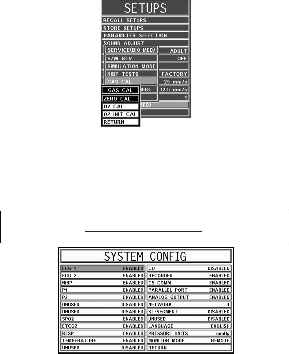
4-14
Figure 4-11. DCU GAS CAL Menu
(5) SYSTEM CONFIG. The SYSTEM CONFIG Menu (See Figure 4-12) is
brought up by selecting the SYSTEM CONFIG Menu Option. Most of the
options in this menu are sensitive and are, as a result, protected by a five
(5) digit password that must be entered before the option may be adjusted.
The Language, Pressure Unit and Network Options are the only options in
this menu which do not require that the service code be entered.
Areas that are “grayed” out cannot be changed at the DCU. These can only
be changed with a WPU hardwired to a VGA display and keyboard.
Figure 4-12. The DCU SYSTEM CONFIG Menu
The following options are available in this menu:
•ECG 1: Selecting this menu option will enable/disable the
ECG 1 module. Not accessible at the DCU.
•ECG 2: Selecting this menu option will Enable/Disable the
ECG 2 module. Not accessible at the DCU. WAR NI NG : This item
is locked.
NOTE
Hardwiring is a service function only.
Refer to Precess Service Manual Part Number 9568.

4-15
•NIBP: Selecting this menu option will Enable/Disable the NIBP
module. Not accessible at the DCU.
•P1: Selecting this menu option will Enable/Disable the P1 module.
Not accessible at the DCU.
•P2: Selecting this menu option will Enable/Disable the P2 module.
Not accessible at the DCU.
•SPO2: Selecting this menu option will Enable/Disable the SpO2
module. Not accessible.
•ETCO2: Selecting this menu option will Enable/Disable the
ETCO2 module (if installed). Not accessible.
•RESP: Selecting this menu option will Enable/Disable the
Respiration module. Not accessible.
•TEMPERATURE: Selecting this menu option will Enable/Disable
the Temperature module. Not accessible.
•CO: This option is for future service enhancement. Not accessible.
•RECORDER: Selecting this menu option will Enable/Disable the
RECORDER module. Accessible with a password.
•CS COMM: Selecting this menu option will Enable/Disable CS
COMM. Not accessible.
•PARALLEL PORT: Selecting this menu option will Enable/
Disable the Parallel/Printer Port. Not accessible.
•ANALOG OUTPUT: Selecting this menu option will Enable/
Disable the Analog Output Port. Accessible with a password.
•NETWORK: Selecting this menu option provides a method of
connecting to a specific network. Accessible without a password.
•ST-SEGMENT: This option is not available on the Precess MRI
Patient Monitoring System. Not accessible.
•LANGUAGE: Selecting this menu option allows the Language of
the monitor to be switched between the available languages
(English, German, Spanish, Portuguese, Italian, Dutch, Swedish
and French). To Enable the language change, the operator must exit
the System Config Menu by selecting Return or pressing the
NORMAL SCREEN Control Key, and then turn the DCU OFF then
ON. Accessible without a password.
•PRESSURE UNITS: Selecting this menu option allows the Blood
Pressure and ETCO2 Measurement units to be switched between
mmHg and kPa. Accessible without a password.
NOTE
When the Pressure Units of measure is changed, the formatting of the value
(i.e. placement of the decimal point) is changed immediately at the DCU, however, it
can take up to 2 seconds for the numeric value(s) being transmitted by the WPU to
reflect the new unit of measure. This can result in an erroneous value being displayed
briefly at the DCU. Note that if the recorder is printing a strip, or a data capture is
performed during this 2 second window, it is possible that this erroneous value may be
recorded.

•MONITOR MODE: This menu item is set automatically
depending on which unit is being viewed. For the DCU, this option
is set to REMOTE Mode. For the WPU, this option is set to
LOCAL Mode. Not accessible at the DCU.
•RETURN: Selecting this menu option returns the display to the
Service (Bio-Med) Menu.
(6) RETURN. Selecting this menu option returns the display to the Normal
Screen.
4.3 Monitor Initialization. The Precess MRI Monitoring System may start its monitoring
functions from either an initial (Factory Settings) state or a pre-configured state depending on
how the stored configuration information and patient data (trends, tabular data, and reports) are
treated on start-up.
4.3.1 Default Initialization. The DCU master processor is “cold-started” by pressing and
holding the Rotary Knob and the NORMAL SCREEN Key while turning power ON. If the
monitor is cold-started, it will revert to Factory Default Settings. The DCU displays the
following:
a. The Bell symbol with “H” in it appears in the upper portion of the screen under
ALARM STATUS.
b. ECG 1 is on in Trace A and set to Lead II.
c. SpO2 is on with waveform displayed in Trace C.
d. NIBP is on and displayed in the lower left portion of the screen.
e. The “SOUND ON HOLD” message is displayed in the center of the screen and
counts down starting from 120.
f. All other parameters are off.
g. The alarm sound is Enabled when the SOUND ON HOLD count reaches 0.
4.3.2 Pre-Configured Initialization. A “warm-start” occurs whenever the DCU or WPU power
is cycled (turned OFF then back ON).
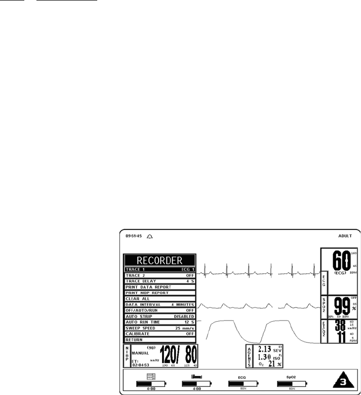
5-1
SECTION 5
RECORDING AND TRENDING
5.0 RECORDING AND TRENDING.
5.1 Introduction. The Precess MRI Patient Monitoring System thermal array strip recorder
can record one or two waveforms (as selected from the RECORDER Menu). The Recorder prints
patient parameters on the edge of the strip chart and ends with a “snapshot” patient data report.
5.1.1 Record Key. The RECORD key Starts/Stops the Recorder upon operator demand. If left
running the recorder will continue to supply hard copy output for approximately 25 seconds
before it automatically shuts Off.
5.2 The Recorder Menu. The RECORDER Menu provides adjustments that will allow this
system to supply concise and up to date printouts suitable to a wide variety of situations. Pressing
the RECORDER SETUP Menu-Select Key brings up the Recorder Menu (See Figure 5-1). If the
recorder is not installed, the message “RECORDER OPTION NOT INSTALLED” is displayed
on the screen. This menu has a time-out feature. If no action is taken for approximately 60
seconds, the display will automatically return to the Normal Screen.
The following is a description of the options in the Recorder Menu:
a. TRACE 1. Selecting this menu option allows the selection of the first Trace to be
output to the Recorder. The options (depending on currently installed parameters)
are ECG1 (default), ECG2, P1, P2, SPO2 and RESP(CO2). If TRACE 2 is OFF,
TRACE 1 is output to the recorder using the full 40 mm width of the printout.
b. TRACE 2. Selecting this menu option allows the selection of the second Trace to
be output to the Recorder. The options (depending on the currently installed
parameters) are OFF (default), ECG1, ECG2, P1, P2, SPO2 and RESP(CO2).
Figure 5-1. The RECORDER Menu
c. TRACE DELAY. Selecting this menu option allows the selection of the Time
Delay for the trace data being sent to the Recorder. The options are 0, 4 (default),
8 and 16 seconds.
d. PRINT DATA REPORT. Selecting this menu option activates the Recorder to
print a patient Data Report (in tabular form) of up to 60 stored patient parameter
readings stored in the time interval preselected by the Data Interval Menu Option
in this menu. Only those Parameters which have been turned ON will be printed.
(1) The Data Report printout consists of the updates (updated per data interval
selection) of the patient parameters (that are on during the data storage
time) up to 60 measurements. The current date and the time of the
recording are clearly marked on the left of the printout.

5-2
(2) If a parameter is off during any portion of the data storage period, the
message ‘---/---’ shall be printed in place of its value.
(3) The Data Report printout ends with a lined area for writing in the ID/CASE
number, the Patient's Name and the Operator Comments.
e. PRINT NIBP REPORT. Selecting this menu option activates the Recorder to
print the NIBP report, with the last 48 NIBP readings in tabular form (6 readings
per page).
f. CLEAR ALL. Pressing this function key erases all data stored for the Data Report
in the system. When pressed, a YES/NO Menu selection box appears that requires
an affirmative operator response before the stored data is cleared. The operation of
this function key requires confirmation by the user.
g. DATA INTERVAL. Selecting this menu option selects the Data Interval
(1 - 60 minutes) for stored patient parameter readings to be printed in the Data
Report (activated by pressing the PRINT DATA REPORT Menu Option in this
menu). The options (in minutes) are 1 through 10 (4 being the default), 12, 15, 18,
24, 30 and 60. The first data stored occurs either at power up, or 2 seconds after a
new interval is selected.
h. OFF/AUTO/RUN. Selecting this menu option allows the switching of the mode
of the Recorder. The options are OFF, AUTO and RUN. The following is an
explanation of the possible selections:
(1) OFF. Switches the Recorder Auto Mode OFF (the recorder may be
activated by pressing the RECORD Control Key.
(2) AUTO. If AUTO is selected, violation of an alarm limit for HR, P1, P2,
NIBP, ETCO2 and SpO2 automatically activates the Recorder Trace and
writes ECG Trace A. In addition to ECG Trace A, a second trace will be
written below it when the Parameter is in a Trace location. The priority of
the second trace recording is RESP(CO2). SpO2 is written as the second
trace recording when its alarm limit is in violation and is the only other
parameter in a trace location.
(a) The recording continues for 20 seconds or until the Recorder is
deactivated by pressing the RECORD Key or by changing the
Recorder Auto Mode to OFF.
(3) RUN. RUN activates the recorder and prints the traces which have been
selected.
i. AUTO STRIP. Selecting this menu option allows the Automatic Report feature of
the Recorder to be switched On and Off. The options are DISABLED, ENABLED
and RETURN. The following is a description of the possible selections:
NOTE
In various menus, the operator may accidentally make a selection that has significant
irreversible effects (e.g.: erasing patient data). To protect against such accidents a
Yes/No Menu is associated with these selections. This menu has only two active
selections: YES and NO. The operator must select one of the two choices to either
confirm the change to take place, or to cancel it. A delay of approximately 30 seconds
without any selection is equivalent to selecting NO. The Yes/No Menu is removed
upon operator selection, at the end of the time-out feature, by pressing the NORMAL
SCREEN button or by pressing the STANDBY button.
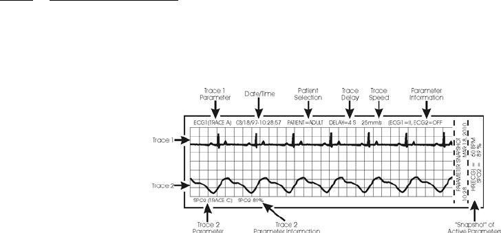
5-3
(1) DISABLED. Selecting this menu option will turn the Automatic Report
Feature OFF.
(2) ENABLED. Selecting this menu option will turn the Automatic Report
Feature ON.
(3) RETURN. Selecting the menu option will return the display to the
Recorder Menu.
j. AUTO RUN TIME. Selecting this menu option brings up the AUTO RUN TIME
Menu where the operator can select the Automatic Strip Run Time. The options are
8, 12, 16, 20 and 30 seconds.
k. SWEEP SPEED. This menu option switches the recorder and the screen Trace
Speed between 25 and 50 mm/second.
l. CALIBRATE. Selecting this menu option opens the CALIBRATE Menu. This
menu option is identical to and interactive with the Calibrate option in the
ECG Menu. The following options are available in the Calibrate Menu:
(1) OFF. Selecting this menu option turns the Calibration feature OFF.
(2) RECORDER. Selecting this menu option sends a 1mV pulse calibration
waveform to the ECG Vital Sign and will also be the ECG waveform
printed by the Recorder if so configured. The message “ECG TEST
SIGNAL” is displayed over the ECG waveform on the screen.
(3) ECG. Selecting this menu option sends a 1mV peak to peak calibration
signal to the ECG vital sign and will also be the ECG waveform printed by
the Recorder if so configured. The message “ECG TEST SIGNAL” is
displayed over the ECG waveform on the screen. It is important to note that
this is a hardware generated calibration waveform and originates as a
square wave by the WECG module.
(4) RETURN. Selecting this menu option closes the Calibrate Menu.
m. RETURN. Selecting this menu option will return the display to the Normal
Screen.
5.3 Recording Charts. This system will print four types of charts upon operator demand.
The four types are Strip Chart, Tabular Chart, Trend Chart and System Data Report. The Sweep
Speed of the printout may be set to 25 mm/second or 50 mm/second with the slower speed
(25 mm/second) presenting the most data on a Strip Chart. Strip Charts, Tabular Charts and
System Data Reports are discussed below (Trend Charts are discussed in Section 5.5).
5.3.1 Strip Chart Record. (See Figure 5-2) The Strip Chart may be configured to contain one or
two Parameter waveforms and also contains the numerical value of every active Parameter as well
as a “Parameter Snapshot” of the current values of every active Parameter at the end of the
printout strip.
Figure 5-2. Sample Strip Chart
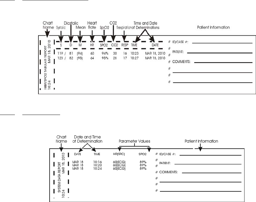
5-4
a. Setting Up the Strip Chart. Perform the following procedure to configure the
Strip Chart to the appropriate application:
(1) Press the RECORDER SETUP Menu-Select Key.
(2) To change Trace 1, which is defaulted to ECG1, press the Rotary Knob,
highlight the desired parameter and press the Rotary Knob to accept the
new selection.
(3) To change Trace 2, which is defaulted to OFF, highlight Trace 2 then press
the Rotary Knob. Highlight the desired parameter and press the Rotary
Knob to accept the new selection.
(4) To set the Trace Delay, which is defaulted to 4 seconds, highlight Trace
Delay then press the Rotary Knob. Highlight the desired delay (the options
are 0, 4, 8 and 16 seconds) and press the Rotary Knob to accept the new
selection.
(5) To set the DCU to provide a Strip Chart automatically, perform the
following:
(a) Select the desired time between automatic strips by highlighting the
Data Interval Menu selection, pressing the Rotary Knob,
highlighting the desired time interval, and pressing the Rotary
Knob to accept the selection.
(b) Set the Auto Strip to ON by highlighting the Auto Strip Menu
selection, pressing the Rotary Knob, highlighting Enabled, and
pressing the Rotary Knob to accept the selection.
(6) To manually print a Strip Chart, press the RECORD Control Key.
5.3.2 Tabular Chart Record. (See Figure 5-3.) The NIBP/SpO2 Tabular Report provides a
hardcopy printout of the numerical indications of NIBP, Heart Rate, SpO2, CO2 and Respiration
along with the date and time of the determination.
Figure 5-3. Sample Tabular Chart
5.3.3 Trend Chart. Trend Charts may be printed for every Parameter being monitored. To print
an individual Trend Chart, first highlight the icon of the Parameter to be printed then press the
TRENDS Menu-Select Key and select the RECORD Menu Option.
Figure 5-4. System Data Report
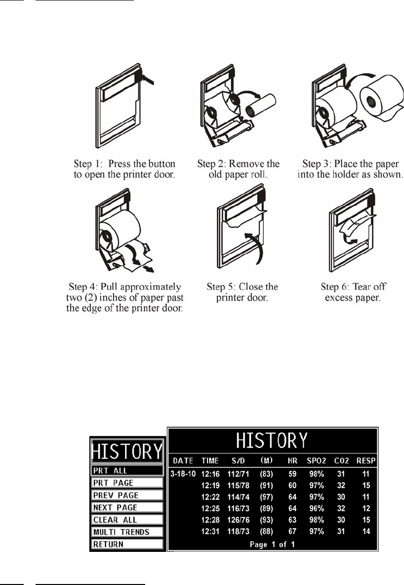
5-5
5.3.4 System Data Report. (See Figure 5-4.) The System Data Report provides a hardcopy
printout of the numerical indications of all the active patient parameters along with the date and
time of the determination.
5.4 Loading Recorder Paper. Perform the procedure in Figure 5-5 to load the recorder
paper.
Figure 5-5. Loading the Recorder Paper
5.5 Trending Feature. The Trend Feature may be operated to graph Multiple or Individual
Trends. Pressing the TRENDS Menu-Select Key, while in the Normal Screen, will bring up the
HISTORY Menu (See Figure 5-6). Pressing it while any Patient Parameter is highlighted will
bring up the Trend Menu for the Selected Patient Parameter. The Precess Vital Signs Monitoring
System automatically stores the Parameter Trend information for the Heart Rate, NIBP, SpO2,
ETCO2 and Respiration. There is also an operational key, CLEAR TRENDS, on the monitor front
panel that allows the operator to clear all trends without bringing up any of the Trends Menus.
Figure 5-6. The HISTORY Menu
5.5.1 History Menu Options. The HISTORY Screen is a Tabular Listing of a patient's NIBP
determinations. The menu provides the option to move from page to page and to print all or part
of the History File. The following is a description of the options available in the HISTORY Menu:
a. PRT ALL. Selecting this menu item will print a complete NIBP History File.
b. PRT PAGE. Selecting this menu item will print the NIBP History File page that
the screen is currently at.
5-6
c. PREV PAGE. Selecting this menu item will change the display to the previous
page of the NIBP History File.
d. NEXT PAGE. Selecting this menu item will change the display to the next page of
the NIBP History File.
e. CLEAR ALL. Selecting this menu item will clear all the data from the NIBP
History File.
f. RETURN. Selecting this menu item will return the display to the Normal Screen.

6-1
SECTION 6
ALARMS
6.0 ALARMS.
6.1 Introduction. The Precess MRI Patient Monitoring System permits user access to every
Parameter Alarm with a single select key. Alarm Limits may be turned on, adjusted (manually or
automatically) or turned off in the Alarms Menu. Individual Parameter Alarms may also be turned
on and/or adjusted by highlighting the Parameter Icon and pressing the ALARMS SCREEN
Menu-Select key.
• The Precess MRI Patient Monitoring System may be set to give visual alarm
signals only (Alarm Limits set, but Alarm Sound off), or both visual and audible
signals (Alarm Limits set, with Alarm Sound on).
• All settings in the Alarms Menu, except the Alarm Sound On/Off and Sound
Mode, can be Stored and Recalled.
6.2 Alarm Limits. The Alarm Limits may be set either manually or automatically. The
Precess MRI Patient Monitoring System provides access to parameter Alarm Limits through a
menu accessed with the ALARMS SCREEN Menu-Select Key. Alarm Limits may be turned On,
adjusted (manually or automatically) or turned Off in the Alarms Menu.
6.2.1 Default (Pre-Set) Alarm Limits. This system will automatically set all the Alarm Limits
to Default settings upon system power up. Table 6-1 provides a listing of Factory Default
Settings. It is important to note that Table 6-1 will not represent the Default Values of your system
if the Default Values are selected by the User.
NOTE
The delay time of making visual alarms available from the alarming equipment to the
remote equipment at signal output port is an average time of two (2) seconds.
The alarms system can be tested using a patient simulator (ECG, NIBP and SpO2) to
exceed the individual parameter alarm limits as required. If a problem with the alarm
tone or message system is suspected, this system must be referred to an Invivo
qualified service technician for evaluation.
NOTE
Setting alarm limits to extreme values can render the alarm monitoring useless.
A potential hazard can exist if different alarm monitoring settings are used for the same
or similar equipment in any single patient care unit.

6-2
Table 6-1. Alarm Limit Factory Default Settings
Adult Values Neonatal Values
Parameter Low Limit High Limit Low Limit High Limit
Heart Rate 45 bpm/
6.0 kPa
160 bpm/
21.3 kPa
90 bpm/
12.0 kPa
210 bpm/
28.0 kPa
NIBP Systolic 65 mmHg/
8.7 kPa
190 mmHg/
25.3 kPa
70 mmHg/
9.3 kPa
100 mmHg/
13.3 kPa
Mean 55 mmHg/
7.3 kPa
135 mmHg/
18.0 kPa
40 mmHg/
5.3 kPa
90 mmHg/
12.0 kPa
Diastolic 40 mmHg/
5.3 kPa
125 mmHg/
16.7 kPa
35 mmHg/
4.7 kPa
50 mmHg/
6.7 kPa
Invasive Pressure Systolic 65 190 Off Off
Mean 55 135 Off Off
Diastolic 40 125 Off Off
Temperature 36°C 39°C Off Off
SpO2 85% Off 90% 98%
ETCO2 15 mmHg/
2.0 kPa
60 mmHg/
8.0 kPa
30 mmHg/
4.0 kPa
45 mmHg/
6.0 kPa
Respiration 4 rpm 40 rpm 30 rpm 70 rpm
ET Halothane Off 1.5 N/A N/A
Fi Halothane Off 2.2 N/A N/A
ET Isoflurane Off 2.3 N/A N/A
Fi Isoflurane Off 3.4 N/A N/A
ET Sevoflurane Off 4.1 N/A N/A
Fi Sevoflurane Off 6.1 N/A N/A
Et Desflurane Off 12 N/A N/A
Fi Desflurane Off 18 N/A N/A
O2 15 99 N/A N/A
CO2 Inspired (Fixed non-adjustable) N/A 25 mmHg/
3.3 kPa
N/A 25 mmHg/
3.3 kPa
N20 (Fixed non-adjustable) N/A 80% N/A 80%

6-3
6.2.2 Range of High and Low Alarm Limits.Each patient parameter has a LOW and HIGH Alarm
Limit value position as indicated by. numerics in the LOW and HIGH columns of
Tab le 6-2 .
The
Alarm Limits displayed in this menu may be changed manually or automatically using the Rotary
Knob after the patient parameter is selected. If a Parameter has been turned OFF from the Setups
Menu, then its LOW and HIGH positions will be OFF on this menu
.
Table 6-2. Range of Alarm Limits
NOTE
The Alarm System automatically prevents the crossover of High and Low Limit
settings.
Input Adult Neonate Unit
Low High Low High
Heart Rate Off, 30 to 249 60 to 249, Off Off, 30 to 249 60 to 249, Off bpm
NIBP Off, 5 to 249
Off, 0.7 to 33.2
5 to 249, Off
0.7 to 33.2, Off
Off, 5 to 249
Off, 0.7 to 33.2
5 to 249, Off
0.7 to 33.2, Off
mmHg
kPa
SpO2 Off, 50 to 99 70 to 99, Off Off, 50 to 99 70 to 99, Off %
Respiration Off, 4 to 40 20 to 150, Off Off, 4 to 40 20 to 150, Off rpm
Invasive Pressure Off, -10 to 249
Off, 0.7 to 33.2
-10 to 249, Off
0.7 to 33.2, Off
Off, 5 to 249
Off, 0.7 to 33.2
5 to 249, Off
0.7 to 33.2, Off
mmHg
kPa
Temperature Off, 20.0 to 44.0 20.0 to 44.0, Off Off, 20.0 to 44.0 20.0 to 44.0, Off °C
ETCO2 Off, 5 to 60
Off, 0.7 to 8.0
5 to 80, Off
0.7 to 10.7, Off
Off, 5 to 60
Off, 0.7 to 8.0
5 to 80, Off
0.7 to 10.7, Off
mmHg
kPa
ET Halothane Off, 0.1 to 5.9 0.1 to 6.0, Off Off, 0.1 to 5.9 0.1 to 6.0, Off %
Fi Halothane Off, 0.1 to 5.9 0.1 to 6.0, Off Off, 0.1 to 5.9 0.1 to 6.0, Off %
ET Isoflurane Off, 0.1 to 5.9 0.1 to 6.0, Off Off, 0.1 to 5.9 0.1 to 6.0, Off %
Fi Isoflurane Off, 0.1 to 5.9 0.1 to 6.0, Off Off, 0.1 to 5.9 0.1 to 6.0, Off %
ET Sevoflurane Off, 0.1 to 8.9 0.1 to 9.0, Off Off, 0.1 to 8.9 0.1 to 9.0, Off %
Fi Sevoflurane Off, 0.1 to 8.9 0.1 to 9.0, Off Off, 0.1 to 8.9 0.1 to 9.0, Off %
Et Desflurane Off, 0.1 to 19.9 0.1 to 20, Off Off, 0.1 to 19.9 0.1 to 20, Off %
Fi Desflurane Off, 0.1 to 19.9 0.1 to 20, Off Off, 0.1 to 19.9 0.1 to 20, Off
O2 15 to 99 15 to 99 15 to 99 15 to 99 %
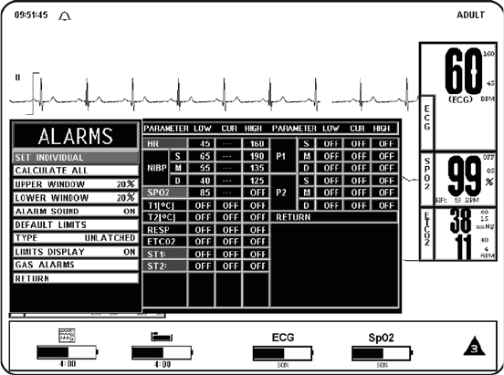
6-4
6.3 Alarm Setup. Pressing the ALARMS SCREEN Menu-Select Key while in the Normal
Monitoring Mode (Normal Screen displayed) with no icons highlighted will bring up the Alarms
Menu (See Figure 6-1).
Figure 6-1. The ALARMS Menu
This menu has the following menu options associated with it:
a. SET INDIVIDUAL. Selecting this menu option allows the operator to adjust
individual Alarm Limits. Once this menu option is selected, turning the Rotary
Knob will allow the operator to scroll through the individual HIGH and LOW
Alarm Limits for manual modification. Once the Limit to be modified is
highlighted, pressing the Rotary Knob selects the Limit and turning the Rotary
Knob changes the value. When the desired setting is shown in the window,
pressing the Rotary Knob again will make the change effective and return to
scrolling through the individual HIGH and LOW Alarm Limits.
b. CALCULATE ALL. Selecting this menu option causes the system to calculate
new Alarm Limit values on all active Parameters at once. The calculations are as
described under UPPER WINDOW and LOWER WINDOW menu options.
c. UPPER WINDOW. Selecting this menu option selects the percent value used in
calculating the HIGH Alarm Limits with the Calculate All menu option. The menu
options are 5%, 10%, 15%, 20% (default), or 30%. The system uses the current
value of the parameter and brackets it with the percentages set by this menu option
and the LOWER WINDOW menu option.
(1) For example, if the patient's Heart Rate is 60, and both percentages have
been set to 10%, activating CALCULATE ALL Menu Option will set the
LOW Alarm Limit to 54 and the HIGH to 66 (plus and minus 10 percent of
the current Heart Rate). Corresponding calculations would be used on each
of the other active patient Parameters to set their LOW and HIGH values.
(2) The following exception applies:
• If the value being monitored from the patient is so high or low that
it would exceed the range of Precess MRI Patient Monitoring
System Alarm Limits (see below), the LOW or HIGH value is set to
the highest or lowest Alarm Limit for that parameter.
6-5
d. LOWER WINDOW. Selecting this menu option selects the percent value that is
used in calculating the LOW Alarm Limits with the Calculate All Menu Option.
The menu options are 5%, 10%, 15%, 20% (default), or 30%. The system uses the
current value of the Parameter and brackets it with the percentages set by this
menu option and the UPPER WINDOW Menu Option.
(1) For example, if the patient's Heart Rate is 60, and both percentage have
been set to 10%, activating CALCULATE ALL would set the LOW Alarm
Limit to 54 and the HIGH to 66 (plus and minus 10 percent of the current
heart rate). Corresponding calculations would be used on each of the other
active patient parameters to set their LOW and HIGH values.
The following exceptions apply:
• If the value being monitored from the patient is so high or low that
it would exceed the range of Precess MRI Patient Monitoring
System Alarm Limits (see below), the LOW or HIGH value is set to
the highest or lowest Alarm Limit for that parameter.
e. ALARM SOUND. Selecting this menu option will turn the Alarm Sound ON/
OFF. When turned OFF, an “X” appears in the Bell symbol on the display and the
Bell symbol in the Menu indicating that the Alarm Sound has been Disabled. This
menu option is identical to, and interactive with, the Alarms Menu Option in the
Sound Adjust Menu.
f. DEFAULT LIMITS. Selecting this menu option causes the system to
automatically set the LOW and HIGH Alarm Limits for all parameters at once
based on the System Defaults (See Default Limits in Appendix A or Table 6-1 for
a listing of the System Default Values).
g. TYPE. Selecting this menu option will select whether the audio and visual alarms
are Latched or Unlatched (see definitions below).
(1) UNLATCHED. The Alarm Tone stops if the violated parameter returns to
within its Limits, or the ALARM SILENCE Key is pressed.
(2) LATCHED. The Alarm Tone will cease only when the ALARM
SILENCE Key is pressed, even if the violating Parameter has returned to
within its Limits.
h. LIMITS DISPLAY. Selecting this menu option will select whether or not the
Alarm Limits are displayed next to the Parameter value in the Normal Screen. The
default is ON.
i. GAS ALARMS. Selecting this menu option will bring up the GAS ALARMS
(Anesthetic Agent Alarm Limits) Menu (See Figure 6-2). All the Alarm Limits
associated with the Anesthetic Agent System are adjusted in this menu. The
following is a description of the Gas Alarms Menu.
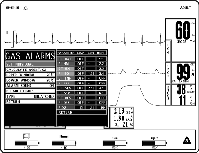
6-6
Figure 6-2. GAS ALARMS (Anesthetic Agents Alarm Limit) Menu
This menu has the following options associated with it:
(1) SET INDIVIDUAL. Selecting this menu option allows the operator to
adjust individual Anesthetic Agent Alarm Limits. Once this menu option is
selected, turning the Rotary Knob will allow the operator to scroll through
the individual Agent Alarm Limits for manual modification. Once the limit
to be modified is highlighted, pressing the Rotary Knob selects the Limit
and turning the Rotary Knob changes the Value. When the desired setting is
shown in the window, pressing the Rotary Knob again will make the
change effective and return to scrolling through the individual Agent
Alarm Limits.
(2) CALCULATE AGENT/O2. Selecting this menu option causes the system
to calculate new alarm limit values on all active Agent and O2 settings at
once. The calculations are as described under UPPER WINDOW and
LOWER WINDOW Menu Options.
(3) UPPER WINDOW. Selecting this menu option selects the percent value
used in calculating the HIGH Alarm Limits with the CALCULATE
AGENT/O2 Menu Option. The menu options are 5%, 10%, 15%, 20%
(default), or 30%. The system uses the current value of the parameter and
brackets it with the percentages set by this menu option and the LOWER
WINDOW Menu Option.
(4) LOWER WINDOW. Selecting this menu option selects the percent value
that is used in calculating the LOW Alarm Limits with the CALCULATE
AGENT/O2 Menu Option. The menu options are 5%, 10%, 15%, 20%
(default), or 30%. The system uses the current value of the parameter and
brackets it with the percentages set by this menu option and the UPPER
WINDOW Menu Option.
(5) ALARM SOUND. Selecting this menu option will turn the Alarm Sound
ON/OFF. When turned OFF, an “X” appears in the Bell symbol on the
display and the Bell symbol in the menu indicating that the Alarm Sound
has been Disabled. This menu option is identical to, and interactive with,
the Alarms Menu Option in the Sound Adjust Menu.

6-7
(6) DEFAULT LIMITS. Selecting this menu option causes the system to
automatically set the LOW and HIGH Alarm Limits for all parameters at
once based on the System Defaults (See Default Limits in Appendix A or
Table 6-1 for a listing of the System Default Values).
(7) TYPE. Selecting this menu option provides the operator the option to
select whether the audio and visual alarms are Latched or Unlatched (see
definitions below).
(a) UNLATCHED. The Alarm Tone stops if the violated Parameter
returns to within its limits, or the ALARM SILENCE Key is
pressed.
(b) LATCHED. The Alarm Tone will cease only when the ALARM
SILENCE Key is pressed, even if the violating Parameter has
returned to within its limits.
(8) RETURN. Selecting this menu option will return the display to the Normal
Screen.
j. RETURN. Selecting this menu option will return the display to the Normal
Screen.
6.3.1 Parameter Alarms Status Screen. While in the ALARMS Screen, the Parameter Alarms
Status Screen is displayed to the right of the Alarms Menu. This screen provides the operator with
the Low and High Alarm Limit Setting along with the Current Measurement value. By using the
SET INDIVIDUAL Menu Option with the Rotary Knob, the operator may adjust all the available
Parameter Limit settings.
6.4 Turning Alarms OFF on Individual Parameters. Alarms may be set to OFF by
pressing the ALARMS SCREEN Menu Select Key, selecting the SET INDIVIDUAL Menu
Option and then scrolling to the desired Parameter to select it and turn it OFF.
6.5 Alarm Violations. An active Alarm Limit is violated when a patient Parameter either
exceeds its HIGH setting or goes below its LOW setting. The alarm system's exact reaction
depends on the settings described in the remainder of this section, but, in general, all alarms
operate as follows:
a. The numerics and trace (if displayed) of the violated Parameter FLASH RED on
the screen.
b. The Alarm Tone on the DCU sounds, if it is Enabled.
c. The numerics continue to flash while the parameter violates its Alarm Limit, even
after the Alarm Tone has been silenced by pressing the ALARM SILENCE Key.
d. If the Printer is in the AUTO Mode, it begins recording. For further information,
see Section 5.
e. The numerics stop flashing after the parameter returns to within its Alarm Limits.
If the alarm system has been set to LATCHED, the numeric continues to flash after
the Parameter returns to within its Alarm Limits, until the ALARM SILENCE
Control Key is pressed.
WARNING
Alarm Limits can be set to a wide range including OFF. It is the responsibility of
the operator of the Precess MRI Patient Monitoring system to ensure that Alarm
Limit values appropriate to each particular patient are established and set.
6-8
f. The numerics of the violated Parameter flash on the display and the audible alarm,
once silenced, will not sound again until after the alarm condition has been
corrected. Only a second (different) parameter alarm will cause the alarm sound to
reactivate.
6.6 Adjusting the Alarm Tone Volume The Alarm Tone is adjusted in the SOUND
ADJUST Menu, which is accessed by selecting the Sound Adjust Menu Option in the Setups
Menu.
6.6.1 Disabling the Alarm Tone The Alarm Tone may be disabled permanently in the
ALARMS Menu or it may be disabled temporarily by pressing the ALARM SILENCE control
key.
a. The ALARM SILENCE Control Key has four functions as follows:
(1) WITH UNLATCHED ALARMS.
(a) If the alarm system has been set to UNLATCHED in the ALARMS
Menu and an Alarm Limit is violated, it silences the alarm tone
when an active Alarm Limit has been violated.
(b) While the Parameter continues to violate its limits, the numeric of
the violated parameter will continue to flash on the screen.
(2) WITH LATCHED ALARMS.
(a) If the alarm system has been set to LATCHED in the ALARMS
Menu and an Alarm is violated, while the parameter continues to
violate its limits it will silence the Alarm Tone. The numeric will
continue to flash, even after the Parameter returns to within its
Alarm Limits.
(b) When the Parameter goes back to within Limits, it will silence the
Alarm Tone, stop the numeric from flashing, and put the Alarm
System into the Alarm Hold Mode.
(c) When the Alarm has been silenced and the Parameter returns to
within Limits, pressing ALARM SILENCE will stop the numeric
from flashing and puts the Alarm System into the Alarm Hold
Mode.
NOTE
The Alarm Tone only applies to the DCU, there is no speaker on the WPU.
WARNING
Once an alarm condition has been silenced it will not sound again for any
reason as long as that alarm condition continues.
For example, if a patients Heart Rate drops below the set limit and
that alarm is silenced, the alarm will never sound that condition
again unless the Heart Rate returns to within limits and then drops
below the limit again.
6-9
(3) ALARM SILENCE. When the system goes into Alarm, pressing the
ALARM SILENCE Control Key silences the Alarm Tone for the current
alarm only. While the DCU is in the Silence mode, the letter “S” is
displayed within the Alarm Status Symbol (Alarm “Bell”), the Alarm Bell
flashes and the text “Alarm Silenced” is displayed in the middle of the
display screen. If any of the silenced alarm conditions return to acceptable
Limits, the monitor will respond according to the above described Latched
and or Unlatched operation. If a new alarm occurs after the Silence Mode is
entered, the DCU will sound the Alarm Tone for the new alarm. Pressing
the ALARM SILENCE Control Key a second time (after entering the
Silence Mode) will place the DCU into the Alarm Hold state.
(4) Alarm Hold “SOUND ON HOLD” Mode. The Alarm Tone must be
turned on (no “X” in the bell shaped Alarm Status Symbol) to enter
SOUND ON HOLD. The Sound on Hold feature is used to temporarily
disable the Alarm Tone. This might be useful, for example, when changing
ECG leads, when drawing blood from an arterial pressure line or for any
user activity which might cause an unwarranted alarm.
(a) When no alarm condition exists, pressing the ALARM SILENCE
Key will activate SOUND ON HOLD (a “SOUND ON HOLD”
message appears in the middle of the screen and an “H” appears in
the Alarm Status Symbol). Just under the message there is a count
down timer starting at 120 (counting down at a 1 second rate)
giving the time left before the Alarm Tone is reactivated.
(b) When an alarm condition exists, if the Alarm Tone is sounding, the
first press of the ALARM SILENCE key stops the Alarm Tone, and
a second press Enables SOUND ON HOLD.
(c) Automatic exit from Alarm Hold. The DCU will automatically
exit alarm hold after 120 seconds, and the “SOUND ON HOLD”
message will disappear from the screen.
(d) Manual exit from Alarm Hold. To exit from Sound on Hold
before 120 seconds, press the ALARM SILENCE Key (which will
remove the “SOUND ON HOLD” message from the screen).
6.7 Standby Mode. Pressing the STANDBY Control Key will place the system into the
Standby Mode. While in the Standby Mode, the system will continue to track and update the
active patient Parameters but three key features will be DISABLED:
•All audible alarms are Disabled. The fact that the Alarms are Disabled is
indicated on the Display Screen by an “X” through the Bell shaped Alarms Status
Symbol. It is also important to note that the Parameter Waveform and/or Numeric
Display continue to operate normally and will turn RED if any active Parameter
violates its Alarm Limits.
•Automatic NIBP Measurements are suspended (if active, the current
measurement will abort).
•No Automatic Printout is generated. When NIBP measurements are resumed,
the initial reading will be taken at the default inflation pressure that is used for all
initial NIBP measurements.

A-1
APPENDIX A
SPECIFICATIONS
GENERAL
PATIENT SAFETY
Conforms to UL STD 60601-1. Certified to CAN/CSA STD C22.2 No. 601.1.
Defibrillator protection up to 5 KV.
POWER REQUIREMENTS
Operating Voltage Range 100 to 240 VAC
Frequency 47 to 65 Hz.
Power Consumption, Maximum < 100 Watts.
BATTERY
Type Lithium-Ion
Operation Time Invivo Part Number 9093 or 9064: As indicated by
battery status display. Maximum operation time of
battery is approximately eight (8) hours when NIBP,
ECG, and SpO2 parameters are running on 5-minute
intervals, and anesthetic agents and EtCO2 are turned
off. (Battery operation time may be reduced by up to
two (2) hours by performing certain operations like
anesthetic agents, printing charts and trends, or short
automatic NIBP cycle times).
Invivo Part Number 9065: Maximum operation time
of the battery is eight (8) hours.
Charge Time Invivo Part Number 9093 or 9064: Time required to
recharge a fully discharged battery is approximately
12 hours with the Precess MRI Patient Monitoring
System turned off.
Invivo Part Number 9065: Time required to recharge a
fully discharged battery is approximately eight
(8) hours.
ENVIRONMENT
Operating Temperature 10 to 40°C (50 to 104o F), or 15 to 35°C (59 to 95°F)
when EtCO2 or anesthetic agents parameters are
operating.

A-2
Storage Temperature Batteries (Invivo Part Numbers 9093 or 9064, and
9065): 0 to 40°C (32 to 104°F).
Disposable Oxygen (O2) Cell (Invivo Part Number
9445): -40 to 45°C (-40 to 113°F).
WPU, DCU, wireless modules, and additional
accessories: -40 to +70°C (-40 to 158°F).
When storing the 3160 system in temperatures beyond
the minimum ranges mentioned above, remove the
designated component and store it appropriately.
Relative Humidity 0 to 80%, non-condensing.
DIMENSIONS
Height WPU: 44.8 inches (113.8 cm) for the caster mount
design, 6 inches (15.2 cm) for the table mount design.
DCU: 12.38 inches (31.5 cm).
Width WPU: 17.5 inches (44.5 cm).
DCU: 15.9 inches (40 cm).
Depth WPU: 17.5 inches (44.5 cm).
DCU: 6.2 inches (15.75 cm).
Weight WPU: 67 lbs. (30.4 Kg).
DCU: 19.35 lbs. (8.78 kg).
DISPLAY
Type 800 x 600 pixel color LCD.
Screen Size 12 inch (30.5 cm) diagonal.
Sweep Speed 25 or 50 mm/S gives 9.2 S or 4.6 S of display
respectively. For respiration, a speed of 0.33, 1.56, 3.13,
6.25, 12.5 or 25 mm/S is used.
GENERAL. DISPLAY. Continued...
Waveform Display Mode Fixed Trace, Moving Erase Bar.
Waveform Display Height >/= 21 mm.
“Full-Screen” Display Height >/= 84 mm.
Display Bandwidth 33 Hz.

A-3
RECORDER (Thermal Array Recorder)
Chart Speeds 25 or 50 mm/second.
Number of Channels 2
Paper Type and Size Non-Grid Thermal Paper, 50 mm wide.
Alphanumeric annotation of date, time delay, paper speed, scales, lead configuration, patient
mode, NIBP (systolic, mean, diastolic), heart rate, respiration rate, Et, FiCO2, Agents Et,
Agents Fi and SpO2.
Automatic activation on alarm with alarm parameter printed at the beginning of trace.
DISPLAYED PARAMETERS
Time Battery-backed quartz crystal clock.
Alarms High and low limits selectable on patient parameters.
ECG ECG Waveform Scale, displayed leads (2).
Heart Rate Normally derived from ECG. May be manually selected to be
derived from invasive blood pressure, pulse oximeter, NIBP or
automatically selected in order of priority.
Pulse Oximeter Pulse Rate, Pulse waveform, percent saturation.
Pressures Systolic, Mean, Diastolic
Temperature One channel of temperature (degree C or degrees F).
Trends Heart Rate, Respiration Rate, NIBP (systolic, mean, diastolic),
IBP (systolic, mean, diastolic), Temperature, ETCO2, and
SpO2.
Respiration Rate Respiration rate derived from ETCO2.
CO2 Both ETCO2 and Inspired CO2.
N2O Inspired N2O, EtN2O available in Agent MAC Box.
O2 Inspired, expired (averaged percent).
Agents Automatic ID of Agent (Desflurane, Isoflurane, Halothane or
Sevoflurane) displaying both End-Tidal Inspired Fraction
Concentrations (Et and Fi). The presence of Enflurane will be
detected, but a concentration value will not be provided.
NIBP Pressures (systolic, mean, diastolic), pulse rate, status.
Trace Freeze Trace A.

A-4
ECG CHANNEL
ECG AMPLIFIER
Protected against defibrillator and electrosurgery potentials.
Standard Lead Configurations I, II, III, AVR, AVL, AVF.
Lead Fail Active, sensing signal imbalance.
HEART RATE
Range 30 to 300 bpm.
Accuracy ±0.5%, ±1 bpm
Resolution 1 bpm.
CARDIOTACH
Sensitivity Adults: > 200 uV.
Neonates/Pediatric ECG mode: > 100 uV.
Pacemaker Pulse Rejection Meets requirements of AAMI EC13-1983
standard for cardiac monitors (Pacer Reject
mode).
Bandwidth Monitor: 0.5 to 40 Hz.
ALARMS
Lower Alarm Limit 30 to 249 bpm (or Off).
Upper Alarm Limit 60 to 249 (or Off).
TEST/CALIBRATION
Square Wave Test Waveform 60 bpm ±1 bpm.
Calibration Signal 1 mV ±10%.

A-5
NON-INVASIVE BLOOD PRESSURE
GENERAL Oscillometric method (with inflatable cuff).
Determines systolic, diastolic and mean arterial
pressures, and pulse rate.
Patient Types Adult and Neonate.
PNEUMATIC SYSTEM
Cuff Inflation Pressure Initially 170 mmHg for Adult/Pediatric.
(120 mmHg for Neonate). Subsequent inflation
pressures determined by last measured systolic
pressure.
Overpressure Protection Adult mode: Automatically releases cuff
pressure if inflation pressure exceeds
285 mmHg.
Neonate mode: 150 absolute, or greater than
142 but less than 150 for 15 seconds).
Unit of Measurement mmHg or KPa.
MEASUREMENT RANGE
Systolic 25 to 260 mmHg.
Diastolic 10 to 235 mmHg.
Mean Arterial 10 to 255 mmHg.
Pulse Rate Range Adult: 40 to 200 bpm
Neonate: 40 to 230 bpm
ACCURACY
Pulse Rate 2% full scale.
Pressure Zero Offset 20 mmHg, ±5 mmHg.
Pressure Span Accuracy ±3 mmHg.
Pressure Transducer Range 0 to 307 mmHg.
ALARM LIMITS
Systolic, Mean and Diastolic Minimum: 5 to 249 mmHg.
Maximum: 5 to 249 mmHg.
Pulse (when “HR” derived from NIBP) Minimum: 30 to 249 bpm.
Maximum: 60 to 249 bpm.
MODES
Manual Immediate upon operator command.
Automatic Determinations automatically made with
selectable intervals of 1, 2, 2.5, 3, 5, 10, 15, 20,
30 and 45 minutes, and 1, 2 and 4 hours.
STAT Up to five (5) consecutive measurements
(five (5) minute maximum time duration).

A-6
PULSE OXIMETER
Pitch of pulse tone is modulated by saturation value.
Saturation Range 0 to 100%.
Saturation Accuracy 70 to 100% ±3%
0 to 69% unspecified.
Pulse Range 30 to 240 bpm ±3 bpm.
Pulse Accuracy ±3 counts.
Averaging Smart algorithm utilizes 4 to 12 seconds data
stream depending on signal to noise ratio.
LED Wavelength LED1: 663 nm
LED2: 948 nm
LED Power Output LED1: 66.9 uW
LED2: 39.1 uW
LED Pulse Duration LED1: 6.06 x 10⁻⁴
LED2: 6.06 x 10⁻⁴
ALARM LIMITS
SpO2 Alarm Limits Low: 50 to 99 or Off.
High: 70 to 99 or Off.
PULSE Alarm Limits (when “HR” derived
from SpO2)
Low: 30 to 249.
High: 60 to 249.

A-7
NOTE
Summary of the SpO2 breath-down study to validate accuracy claims according to the
requirements of ISO 9919:2005. Particular Requirements for the Basic Safety and
Essential Performance of Pulse Oximeter Equipment for Medical Use
The Precess patient monitor and the wireless SpO2 module (Part Number 9311) were
validated in a breathe-down study at the San Francisco VA Hospital, Anesthesia
Research Service. Sp02 values displayed by the Precess patient monitor were
statistically compared against gold-standard Radiometer OSM-3 Co-oximeter
functional SaO2 values to determine scientific accuracy. Twelve volunteers were
chosen based upon San Francisco UCSF IRB rules and regulations. Volunteers
participated in the breathe-down protocols at rest while fully conscious at SaO2 values
ranging from 70-100%. Twenty radial arterial blood samples were withdrawn from
each volunteer during observed SaO2 plateaus and analyzed by co-oximetry.
Immediately after collecting each blood sample, a functional SpO2 value was recorded
from the patient monitor display. Functional SpO2 and SaO2 values were compared
using Bland-Altman statistical analysis to demonstrate accuracy through the
production of Arms, Bias and Precision values. Clinical validation for Invivo Model
9311 Wireless Pulse Oximeter Module with Invivo Model 9399B Reusable Sensor
demonstrated on accuracy value of 1.91% Arms in the range 70-100% SaO2. This
Arms value is consistent with the model 9311 accuracy specification for each sensor
(Adult/Pediatric 2.0% Arms).
PULSE OXIMETER. Continued...
NOTE
The information regarding wavelength can be especially useful to clinicians.
An SpO2 functional tester (e.g. patient simulator) only measures the accuracy of a
monitor for a particular calibration curve. It must not be used to assess the accuracy of
a monitor in reference to a direct blood gas measurement. Because SpO2
measurements are statistically distributed, it is possible that only two-thirds of the
measurements will fall within ±1.54% of the value measured by a CO-Oximeter. A
functional tester may, however, be used to test alarm signal generation by exceeding
the alarm limits.
The probe must be repositioned every 4 to 8 hours. Do not use the probe under an
electric blanket or on a heating pad.

A-8
INVASIVE PRESSURE CHANNELS (Optional)
PRESSURE AMPLIFIER
Range -10 to +248 mmHg.
Sensitivity 5 uV/V/mmHg.
Gain Accuracy ±0.5%.
Bandwidth 0 to 12 Hz (-3 dB).
AUTO ZERO
Range +300 mmHg.
Zero Accuracy ±1.0 mmHg.
Response Time 1 second, notifies operator when done.
PRESSURE WAVE DISPLAY
Number of Channels 0, 1 or 2.
ART, PAP and LAP Numeric display of systolic, mean and diastolic
pressures.
CVP and ICP Numeric display of mean pressure only.
PRESSURE SCALE RANGES
(User Selectable)
0 to +250 mmHg (0 to 33.3 kPa).
0 to +200 mmHg (0 to 26.7 kPa).
0 to +150 mmHg (0 to 20.0 kPa).
0 to + 75 mmHg (0 to 10.0 kPa).
0 to + 45 mmHg (0 to 6.0 kPa).
PULSE RATE (When derived from P1 or P2)
Range 30 to 249 bpm.
Accuracy 2% of full scale.
Resolution 1 bpm.
ALARMS
Transducer Disconnect Alarm delay 4 seconds.
Pressure Disconnect Alarm delay 4 seconds.
High and Low Pressure Alarm delay 4 seconds.

A-9
ALARM LIMITS
Heart Rate Low: 30 to 249 bpm
High: 60 to 249 bpm
Systolic, Mean, Diastolic Systolic, Mean, Diastolic:
Low: -10 to 249 bpm
High: -10 to 249 bpm
INVASIVE PRESSURE CHANNELS. Continued...
TRANSDUCER ADAPTER CABLE COMPATIBILITY
Invasive pressure input mates with an Amphenol connector (MS-3106A 14S-6P). With this con-
nector and the following connection information, transducer adapter cables may be made or
ordered from various transducer adapter cable manufacturers.
Connector Pin # Signal Name
A- Signal
B + Excitation
C + Signal
D - Excitation
E Shield

A-10
Low-Flow End-Tidal CO2 [Optional]
Side stream, non-dispersive infrared absorption technique. Including multiple water trapped
filtration system and microprocessor logic control of sample handling and calibration.
Output CO2 Waveform, ETCO2, FiCO2, Respiration
Rate.
Units of measurement mmHg or KPa.
Measurement Range CO2: 0 to 76 mmHg.
Accuracy CO2: ±4 mmHg or ±12%, whichever is greater.
Resp: ±1 Respiration/minute (RPM) or ±3%,
whichever is greater.
Warm-up Time < 2 minutes.
Zero Calibration Interval Automatic or user requested.
Flow Rate 80 mL/minute ±16mL/minute.
Respiration Rate
(Rate permitting specified EtCO2
accuracy)
Accuracy: 0 to 60 respirations/minute.
Respiration Range 4 to 100 respirations/minute.
Total System Response Time From 2.5% CO2 to 5% CO2 Avg. value of
14.313 seconds.
From Ambient Air to 5% CO2 Avg. value of
14.193 seconds.
Drift 0% Drift was observed during a 6 hour period.
Sample Cell Volume < 50 micro liters.
Operating Temperature 15 to 35°C (59 to 95°F)
ALARM LIMITS
ETCO2 Alarm Limits Low: OFF or 5 to 60 mmHg
High: 7 to 80 or OFF mmHg
Inspired CO2 25 mmHg (Fixed)
Respiration Alarm Limits Low: OFF or 4 to 40 RPM
High: 20 to 150 ROM or OFF
MEASURED
GAS
INTERFERING GASES AND EFFECTS
N20 HAL ENF ISO SEVO Xenon Helium DES Ethanol Isopropanol Acetone Methane
Carbon
Dioxide
NE @
60%
NE @
4%
NE @
5%
NE @
5%
NE @
5%
ME @
80%
ME @
50%
NE @
15%
NE @
5%
NE @
0.548%
NE @
2%
NE @
2%

A-11
No Effect (NE) = Total Error < 10%.
Minimal Effect (ME) = Total Error > 10%, but within Specification.
Interferes (INT) = Total Error > 15% of Measured Value + 0.2 of the Interfering Gas Value, or False Positive ID occurs.
MEASURED
GAS
INTERFERING GASES AND EFFECTS

A-12
ANESTHETIC AGENTS (Optional)
Technique Side Stream, non-dispersive infrared (NDIR) absorption
technique, including water trap filtration system and
microprocessor logic control of sample handling and
calibration.
Measurement Range (after
maximum warm-up period)
Halothane: 0.15 to 6.0 Vol.%.
Isoflurane: 0.15 to 6.0 Vol.%.
Sevoflurane: 0.15 to 9.0 Vol.%.
Desflurane: 0.15 to 20 Vol.%.
Enflurane: Identification. No measurement.
Carbon Dioxide: 0 to 76 mmHg.
Nitrous Oxide: 5 to 100 Vol.%.
Accuracy * Halothane: ±0.15 Vol.% + 12% relative,.
Isoflurane: ±0.15 Vol.% + 12% relative.
Sevoflurane: ±0.15 Vol.% + 12% relative.
Desflurane: ±0.15 Vol% + 12% relative.
Enflurane: Identification. No measurement.
Carbon Dioxide: (measured with agent option) ±3mmHg or
12%, whichever is greater.
Nitrous Oxide: (measured with agent option) ±2% Vol., + 8%
relative (at volumes greater than 5%).
* Gas measurement performance requirements are met after the
maximum warm-up period (20 minutes).
Zero Drift Rate CO2 < 1mmHg/Hr.
N2O < 2%/Hr to < 5%/24Hr maximum.
Calibration Interval Calibration verification (as described in service instructions)
must be performed on a 1 year interval.
Flow Rate 230 ±40 mL/min.
Response Time (assuming a
gas flow of 230 mL/min for a
step change of between 10 to
90%)
Agents: Not specified.
CO2: < 700 mSec.
Respiration Rate
(Range permitting specified
gas accuracy): *
4 to 20 rpm (Respirations per Minute).
* This is the breath rate range in which the system measures the
respiration rate within the accuracy requirements for
respiration rate.
Respiration Range 0 to 60 rpm (based on CO2 measurements).
Relevant Interference 0.5 mmHg equivalent with 37.5°C saturated with H2O
(0.1% relative max).
Display Resolution: 0.01% Volume.
Operating Temperature 15°C to 35°C.

A-13
ANESTHETIC AGENTS. Continued...
Maximum Warm-up Time: 20 minutes
Auto ID Threshold: (refer to
paragraph 3.5.4 for warm-up
information)
0.15 ±Accuracy Vol% for all gases.
Multiple Agents Alarm
Threshold:
The equivalent impurity of 0.3% volume or 30% of the primary
anesthetic agent gas (whichever is greater).
NOTE
Except for combinations of Isoflurane and Sevoflurane,
where the concentration of Sevoflurane that shall trigger
the agent mix alarm is 0.3%.
END-TIDAL CO2
Operational and Storage
Atmospheric Pressure
500 kPa to 1060 kPa
Rise Time Adult: 400 ms (±10 ms).
Neonate: 200 ms (±10 ms).
Ambient Pressure
Compensation Range
523 to 788 mmHg.
ALARM LIMITS
ETCO2 Alarm Limits Low: OFF or 5 to 60 mmHg.
High: 5 to 80 mmHg or OFF.
Inspired CO2 25 mmHg (Fixed).
N2O 80% (Fixed).
ET Halothane Low: Off, 0.1 to 5.9
High: 0.1 to 6.0, Off
Fi Halothane Low: Off, 0.1 to 5.9
High: 0.1 to 6.0, Off
ET Isoflurane Low: Off, 0.1 to 5.9
High: 0.1 to 6.0, Off
Fi Isoflurane Low: Off, 0.1 to 5.9
High: 0.1 to 6.0, Off
ET Sevoflurane Low: Off, 0.1 to 8.9
High: 0.1 to 9.0, Off
Fi Sevoflurane Low: Off, 0.1 to 8.9
High: 0.1 to 9.0, Off

A-14
ANESTHETIC AGENTS. ALARM LIMITS. Continued...
ET Desflurane Low: Off, 0.1 to 20
High: 0.1 to 20, Off
Fi Desflurane Low: Off, 0.1 to 20
High: 0.1 to 20, Off
O2 Low: 15 to 99
High: 15 to 99
OXYGEN
Range 0 - 100%.
Signal Output (at constant
temperature and pressure)
14 ±±4 mV.
Maximum Response Time
(10 to 90%)
10 Seconds.
Accuracy, Full Scale * ±3%.
* Gas measurement performance requirements are met after the maximum warm-up period.
Accuracy, Full Scale, Over
Operating Temperature
±5%.
Drift < 1%/Month.
Linearity ±1% of Full Scale.
Operating Temperatures 0 to +40 °C.
Ambient Humidity (Non-
Condensing)
0 - 99% RH (Non-Condensing).
Oxygen Sensor, Expected
Life
12 months (> 100,000 Oxygen%/hours).
Oxygen Sensor, Storage
Temperature
-10 to 45°C.
Oxygen Sensor, Shelf Life < 6 Months (in unopened bag).

A-15
ANESTHETIC AGENTS. OXYGEN. Continued...
Interfering Gas Effects:
N2O
CO2
Halothane
Enflurane
Isoflurane
Desflurane
Helium
Methoxyflurane
Diethyl Ether
Trichloroethylene
Nitric Oxide
< 2 Vol.% @ 80 Vol.% N2O.
< 2 Vol.% @ 5 Vol.% CO2.
< 2 Vol.% @ 4 Vol.% Halothane.
< 2 Vol.% @ 5 Vol.% Enflurane.
< 2 Vol.% @ 5 Vol.% Isoflurane.
< 2 Vol.% @ 15 Vol.% Desflurane.
< 2 Vol.% @ 50 Vol.% Helium.
No Known Effects.
< 2 Vol.% @ 50 Vol.% Diethyl Ether.
No Known Effects.
< 2 Vol.% @ 100 PPM Nitric Oxide.
Temperature (Optional)
TEMPERATURE
For use with Invivo Fiber-Optic Temperature Sensors which utilize Fabry-Perot Interferometer
Technology.
Channel One.
Scales Degrees C or Degrees F.
Range 20.0 to 44.0°C (68.0 to 111.2°F).
Resolution 0.1°C (0.1°F).
Accuracy 0.5°C (0.9°F).
Average Time Constant One (1) second.
Numeric Display Update Time Two (2) seconds.
Sensor Type Semi-reusable fiber-optic.
TEMP ALARM LIMITS
Degrees C Low: Off, 20.0, 44.0
High: 20.0, 44.0, Off
Degrees F Low: Off, 68.0, 111.2
High: 68.0, 111.2, Off

A-16
WECG/WSPO2 3.7V Battery Charger (Part Number 9023)
POWER REQUIREMENTS
Input Voltage (to AC adapter) Universal AC; 85 to 265VAC @ 47 to 63Hz.
Input Power 40W without power factor correction.
Grounding Connection Hospital Grade (with earth ground).
Protection Over/under voltage, reverse voltage, under current.
DC Connector 24 Vdc power pack.
ENVIRONMENT
Location Console Room (outside of MRI magnet room)
Operating Temperature 0 to 40°C (32 to 104°F).
CHARGING CHARACTERISTICS
Battery Charge Time 8 hours maximum from fully discharged to fully
charged.
Battery Presence Detection Microswitch; charging and LED indication start
immediately upon detection.
Battery Type 3.7V lithium-ion, 0.64+ Amp-Hours.
Battery Charge Control Constant current/constant voltage format, “wake-up”
charge on fully discharged batteries, battery data
communication verification.
DIMENSIONS
Height 3.23 inches (8.20 cm).
Width 7.98 inches (20.27 cm)
Depth 5.54 inches (14.07 cm)

B-1
APPENDIX B
REPAIR
All repairs on products under warranty must be performed by Invivo personnel or an authorized
Invivo Service and Repair Center. Unauthorized repairs will void the warranty.
If a Precess MRI Patient Monitoring System fails to function properly or requires maintenance,
contact Invivo Technical Service at 1-800-331-3220 during normal business hours EST or
24-hour emergency technical assistance. Invivo Technical Service will advise you of the
corrective action required. If you are advised to return the system to Invivo for repair, please do
the following:
1 Obtain a Return Authorization Number. This will ensure proper routing and facilitate
timely repair of your system.
2 Remove the batteries (Invivo Part Numbers 9093 or 9064, and 9065) from the Precess
MRI Patient Monitoring System (including wireless modules). Package the system with
adequate protection. If available, use the original carton and packing material in which the
system was shipped from Invivo. Do not ship the batteries to Invivo when returning the
system for repair.
If the batteries are the source of system malfunction, consult an Invivo Technical Service
Representative for additional assistance.
3 Include a brief description of the problem as well as the name, address and phone number
of the person to be contacted for additional information.
4 Include the original purchase order with the system being returned. Invivo Technical
Services will tell you if your system is still under warranty based on the date of purchase.
5 Repairs will be made at Invivo's current list price for the replacement part(s) plus a
reasonable labor charge.
6 Ship the system, transportation prepaid, to the location specified by your Invivo Technical
Service Representative with the Return Authorization Number written on the outside of
the shipping carton. Repairs will be made within two weeks and the system will be
returned to you prepaid.
Technical Service Department
Invivo Corp.
12501 Research Parkway
Orlando, FL 32826
(407) 275-3220
NOTE
Lithium-ion batteries are subject to strict packaging and shipping laws. Failure to
observe these laws may result in severe penalties. Therefore, do not ship the batteries
(Invivo Part Numbers 9093, 9064, or 9065) when returning the system for repair.
NOTE
The recommended preventative maintenance interval is one year for this product. For
further details, please reference the Precess (Model 3160) Service Manual (Part
Number 9568).

To ensure full reliability, it is recommended that all repairs be made by an Invivo Authorized
Service and Repair center. For repair at your facility, a competent individual experienced in the
repair of the Precess MRI Patient Monitoring Systems can repair the system only if it is
authorized by Invivo Technical Service prior to the repair. No repair should ever be undertaken or
attempted by anyone not having a thorough knowledge of the repair of Invivo monitors.
CAUTION
No repair should ever be undertaken or attempted by anyone not having a thorough
knowledge of the repair of Invivo patient monitoring systems. Only replace damaged
parts with components manufactured or sold by Invivo. Contact the Invivo Technical
Service and Repair Center for service and technical assistance.
C-1
APPENDIX C
WARRANTY
Invivo warrants this product, other than its expendable parts, to be free from defects in materials
and workmanship for a period of twelve (12) months from the date of original delivery to the
buyer or to buyer's order, provided that same is properly operated under conditions of normal use,
and that periodic maintenance and service is performed. This same warranty is made for a period
of thirty (30) days on expendable parts. This warranty shall become null and void if the Precess
MRI Patient Monitoring System has been repaired by someone other than Invivo or if the product
has been subject to misuse, accident, negligence or abuse.
Invivo's sole obligation under this warranty is limited to repairing a Precess MRI Patient
Monitoring System which has been reported to Invivo's Technical Service Center during normal
business hours and shipped transportation prepaid. Invivo shall not be liable for any damages
including but not limited to incidental damages, consequential damages or special damages.
This warranty is in lieu of any other warranties, guarantees or conditions, including
merchantability or fitness for a particular purpose. The remedies under this warranty are exclusive
and Invivo neither assumes nor authorizes anyone to assume for it any other obligation in
connection with the sale or repair of its products.
INVIVO PRODUCTS CONTAIN PROPRIETARY COPY WRITTEN MATERIAL.
ALL RIGHTS ARE RESERVED BY INVIVO CORP.
D-1
APPENDIX D
DECLARATION OF CONFORMITY
For further information, contact the Regulatory Affairs Department of Invivo Corporation at
telephone number 407-275-3220.
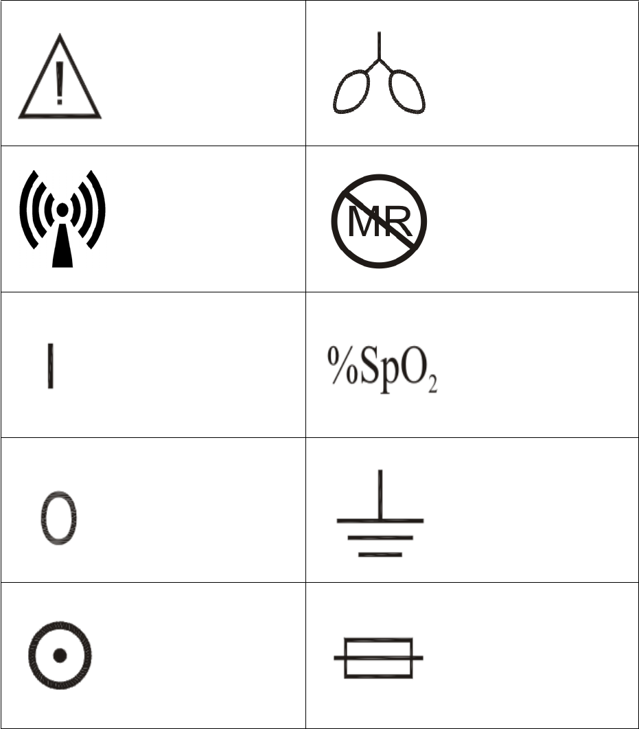
E-1
APPENDIX E
LIST OF SYMBOLS
Attention, Consult
Accompanying
Documents
Breathing Effort
Detected
Non-ionizing
Radiation Symbol Not MRI Compatible
ON (Main Power) Percent Oxygen
Pulse Saturation
OFF (Main Power) Earth (Ground)
“ON” (For part of the
equipment) Fuse
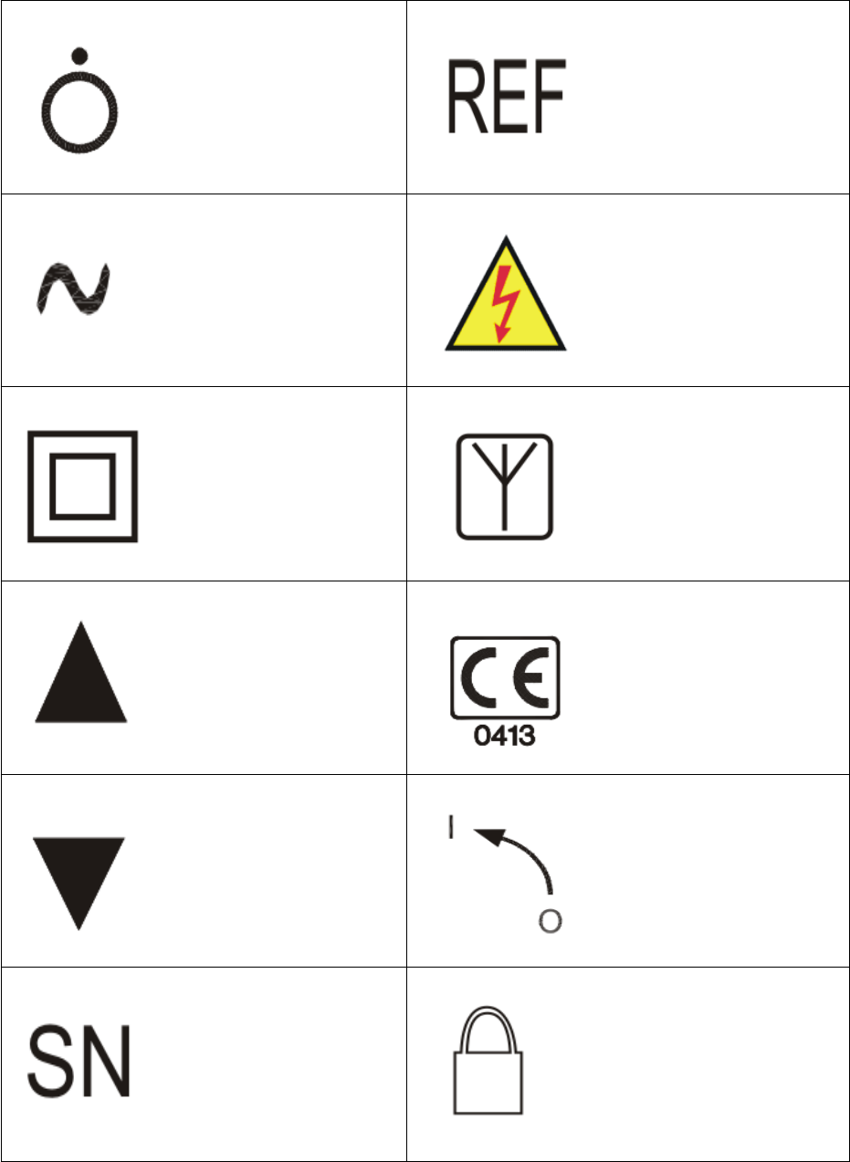
E-2
“OFF” (For part of the
equipment) Product Part Number
Alternating Current DANGER!
High Voltage
Class II Equipment Antenna
Up/Increment
Device conforms to the
Medical Device
Directive
Down/Decrement
I (Rotate Counter-
clockwise to OPEN)
O (Rotate Clockwise to
CLOSE)
Product Serial Number Locked
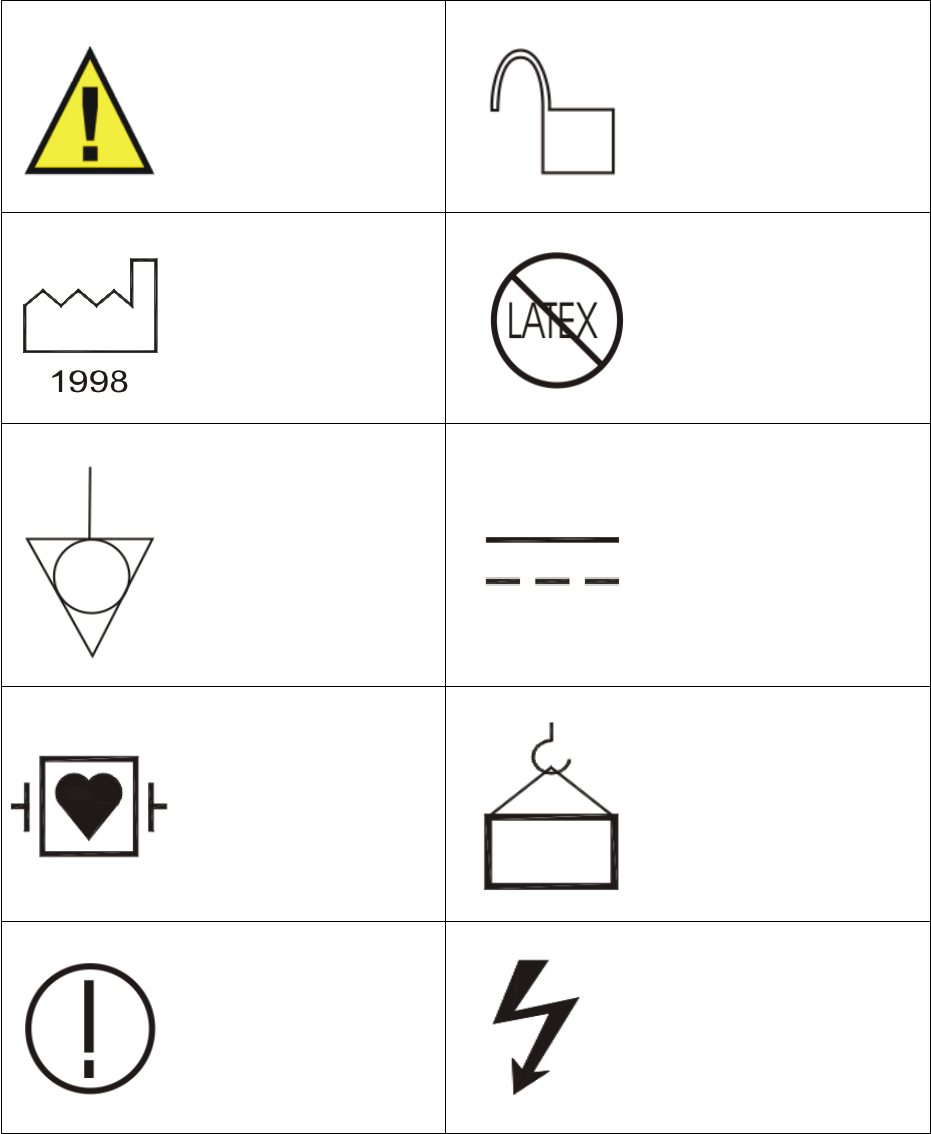
E-3
Attention!
Precautionary Alert Unlocked
Date of Manufacture Latex-Free Materials
Are Used
Equipotential
Connection Direct Current
Defibrillator-Proof
Type CF Equipment
(IEC 60601-1)
Protection Against
Shock
Weight
Potential restrictions
may apply within one or
more European (EU)
member states.
Dangerous
Voltage
E-4
Type CF Applied Part Patient
Alarms ON Single Patient Use Only
DO NOT REUSE
Alarms Silenced Replace Fuses As
Marked
Heart Beat Detected
Attention:
Electrostatic Safety
Device
Observe Precautions
Input/Output
Battery
Non-Invasive
Blood Pressure
Universal Serial Bus
(USB)
E-5
Oxygen Sensor
Access Here Keyboard
On AC Power ECG
On Battery Power Remote Display
Low Battery Serial Communications
Port
Fiber-Optic
Temperature
Danger Flammable
Anesthetics
End-Tidal CO2 /
O2/Anesthetic Agents
Danger Possible
Explosion Hazard
Warning Shock
Hazard Pneumatic Respiration
E-6
Do Not Adjust
Without Referring
To Service Manual
Radio Network
(Wireless Modules)
Hardwire Link Network No. 1
Waste Gas Output Network No. 2
End-Tidal CO2/
O2/Anesthetic Agents
Input
Network No. 3
Cardiac (ECG)
Gating Output Network No. 4
MR Conditional Network No. 5
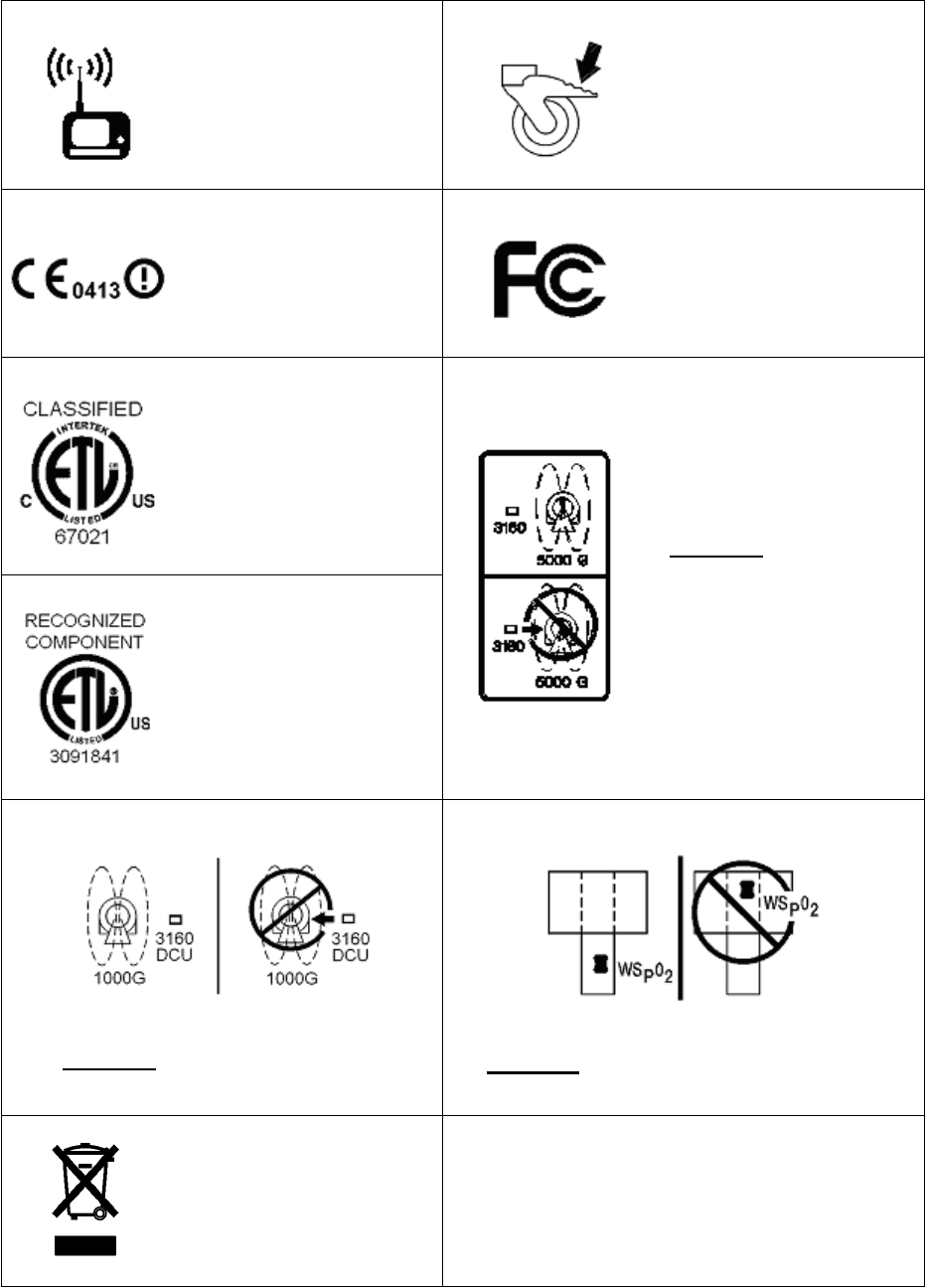
E-7
Radio Network
(Precess™ WPU Base to
DCU)
Wheel Brake
CE and R&TTE
Markings
Federal
Communications
Commission
Intertek Classified
ETL Mark
DO NOT Move
Precess™ Inside
5,000 Gauss Line
Intertek Recognized
Component ETL Mark
DO NOT Move Precess™ DCU
With Recorder Inside 1,000 Gauss Line
DO NOT Place SPO2 Wireless Module
In Bore
Dispose of in accordance
with your country’s
requirements

F-1
APPENDIX F
EMC
Frequency Range: 2402 to 2482 MHz.
Modulation Type: GMSK.
WPU EIRP: 4.2 dBm (peak).
WECG and WSPO2 EIRP: 0 dBm (peak).
WARNING
Operation of the Precess MRI Patient Monitoring System below the
specifications indicated in Appendix A will cause inaccurate results.
The use of accessories, transducers and cables other than those specified in the
Accessories list of this Operation Manual (with the exception of transducers and
cables sold by Invivo for the equipment or system as replacement parts for
internal components) will result in increased emissions or decreased immunity
of the equipment or system.
The Precess MRI Patient Monitoring System should not be used adjacent to or
stacked with other equipment and that if adjacent or stacked use is necessary,
the equipment or system must be observed to verify normal operation in the
configuration in which it will be used.
The Precess MRI Patient Monitoring System may be interfered with by other
equipment with CISPR emission requirements.
WARNING
The Precess MRI Patient Monitoring System needs to be installed and put into
service according to the EMC information provided in this manual.
Portable and Mobile RF communications equipment can affect medical electrical
equipment.
Guidance And Manufacturer’s Declaration - Electromagnetic Emissions
The Precess MRI Patient Monitoring System is intended for use in the electromagnetic
environment specified below. The customer or the user of the Precess MRI Patient
Monitoring System should assure that it is used in such an environment.
Emissions Test Compliance Electromagnetic Environment - Guidance
RF Emissions
CISPR 11
Group 1 The Precess MRI Patient Monitoring System
uses RF energy only for its internal functions.
Therefore, its RF emissions are very low and
are not likely to cause any interference in
nearby electronic equipment.
RF Emissions
CISPR 11
Class A The Precess MRI Patient Monitoring System
is suitable for use in all establishments, other
than domestic establishments and those
directly connected to the public low-voltage
power supply network that supplies buildings
used for domestic purposes.
Harmonic Emissions
IEC 61000-3-2
Class A
Voltage Fluctuations/
flicker emissions
IEC 61000-3-3
Complies

F-2
Guidance And Manufacturer’s Declaration - Electromagnetic Immunity
The Precess MRI Patient Monitoring System is intended for use in the electromagnetic environment
specified below. The customer or the user of the Precess MRI Patient Monitoring System should
assure that it is used in such an environment.
Immunity Test IEC 60601
Test Level
Compliance Level Electromagnetic
Environment - Guidance
Electrostatic
discharge (ESD)
IEC 61000-4-2
±6kV contact
±8kV air
±6kV contact
±8kV air
Floors should be wood,
concrete or ceramic tile. If
floors are covered with
synthetic material, the
relative humidity should
be at least 30%.
Electrical fast
transient/burst
IEC 61000-4-4
±2kV for power
supply lines
±1kV for input/
output lines
±2kV for power
supply lines
±1kV for input/ output
lines
Mains power quality
should be that of a typical
commercial or hospital
environment.
Surge
IEC 61000-4-5
±1kV differential
mode
±2kV common
mode
±1kV differential
mode
±2kV common mode
Mains power quality
should be that of a typical
commercial or hospital
environment.
Voltage dips, short
interruptions and
voltage variations on
power supply input
lines
IEC 61000-4-11
< 5% Ut
(> 95% dip in Ut)
for 0.5 cycle
40% Ut
(60% dip in Ut) for
5 cycles
70% Ut
(30% dip in Ut) for
25 cycles
< 5% Ut
(> 95% dip in Ut)
for 5 seconds
< 5% Ut
(> 95% dip in Ut) for
0.5 cycle
40% Ut
(60% dip in Ut) for
5 cycles
70% Ut
(30% dip in Ut) for
25 cycles
< 5% Ut
(> 95% dip in Ut) for
5 seconds
Mains power quality
should be that of a typical
commercial or hospital
environment. If the user of
the Precess MRI Patient
Monitoring System
requires continued
operation during power
mains interruptions, it is
recommended that the
Precess MRI Patient
Monitoring System be
powered from an
uninterruptable power
supply or battery.
Power frequency
(50/60 Hz)
magnetic field
IEC 61000-4-8
3 A/m 3 A/m Power frequency magnetic
fields should be at levels
characteristic of a typical
location in a typical
commercial or hospital
environment.
NOTE: Ut is the a.c. mains voltage prior to application of the test level.
F-3
Guidance And Manufacturer’s Declaration - Electromagnetic Immunity
The Precess MRI Patient Monitoring System is intended for use in the electromagnetic environment
specified below. The customer or the user of the Precess MRI Patient Monitoring System should assure that
it is used in such an environment.
Immunity Test IEC 60601
Test Level
Compliance
Level
Electromagnetic Environment - Guidance
Conducted RF
IEC 61000-4-6
Radiated RF
IEC 61000-4-3
3 Vrms
150 KHz to 80 MHz
3 V/m
80 MHz to 2.5 GHz
V1 = 3 Vrms
E1 = 3 V/m
Portable and mobile RF communications
equipment should not be used no closer to any
part of the Precess MRI Patient Monitoring
System, including cables, than the
recommended separation distance calculated
from the equation applicable to the frequency
of the transmitter.
Recommended separation distance
d = (3.5/V1)
d = (3.5/E1)
(80 MHz to 800 MHz)
d = (7/E1)
(800 MHz to 2.5 GHz)
Where P is the maximum output power rating of
the transmitter in watts (W) according to the
transmitter manufacturer and d is the
recommended separation distance in meters (m).
Field strengths from fixed RF transmitters, as
determined by an electromagnetic site survey,a
should be less than the compliance level in each
frequency range.b
Interference may occur in the vicinity of
equipment marked with the following symbol:
NOTE 1: At 80 MHz and 800 MHz, the higher frequency range applies.
NOTE 2: These guidelines may not apply in all situations. Electromagnetic propagation is affected by absorption and reflection
from structures, objects and people.
aField strengths from fixed transmitters, such as base stations for radio (cellular/cordless) telephones and land mobile radios,
amateur radio, AM and FM radio broadcast and TV broadcast cannot be predicted theoretically with accuracy. To assess the
electromagnetic environment due to fixed RF transmitters, an electromagnetic site survey should be considered. If the measured
field strength in the location in which the Precess MRI Patient Monitoring System is used exceeds the applicable RF compliance
level above, the Precess MRI Patient Monitoring System should be observed to verify normal operation. If abnormal performance
is observed, additional measures may be necessary, such as re-orienting or relocating the Precess MRI Patient Monitoring System.
bOver the frequency range 150 KHz to 80 MHz, field strengths should be less than 3 V/m.
P
P
P

F-4
Recommended Separation Distances Between Portable And Mobile RF
Communications Equipment And The Precess MRI Patient Monitoring System
The Precess MRI Patient Monitoring System is intended for use in an electromagnetic environment
in which radiated RF disturbances are controlled. The customer or the user of the Precess MRI
Patient Monitoring System can help prevent electromagnetic interference by maintaining a minimum
distance between portable and mobile RF communications equipment (transmitters) and the Precess
MRI Patient Monitoring System as recommended below, according to the maximum output power of
the communications equipment.
Rated Maximum Output
Power Of Transmitter
W
Separation Distance According To Frequency Of Transmitter
m
150 KHz to 80 MHz
d = (3.5/V1)
80 MHz to 800 MHz
d = (3.5/E1)
800 MHz to 2.5 GHz
d = (7/E1)
0.01 0.117 0.117 0.233
0.1 0.369 0.369 0.738
1 1.167 1.167 2.333
10 3.689 3.689 7.379
100 11.667 11.667 23.333
For transmitters rated at a minimum output power not listed above, the recommended separation
distance d in meters (m) can be estimated using the equation applicable to the frequency of the
transmitter, where P is the maximum output power rating of the transmitter in watts (W) according to
the transmitter manufacturer.
NOTE 1: At 80 MHz and 800 MHz, the separation distance for the higher frequency range applies.
NOTE 2: These guidelines may not apply in all situations. Electromagnetic propagation is affected
by absorption and reflection from structures, objects and people.
P P P
G-1
APPENDIX G
NOTES