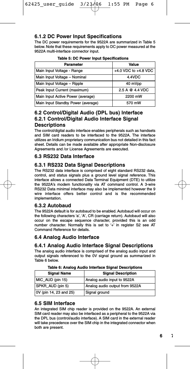
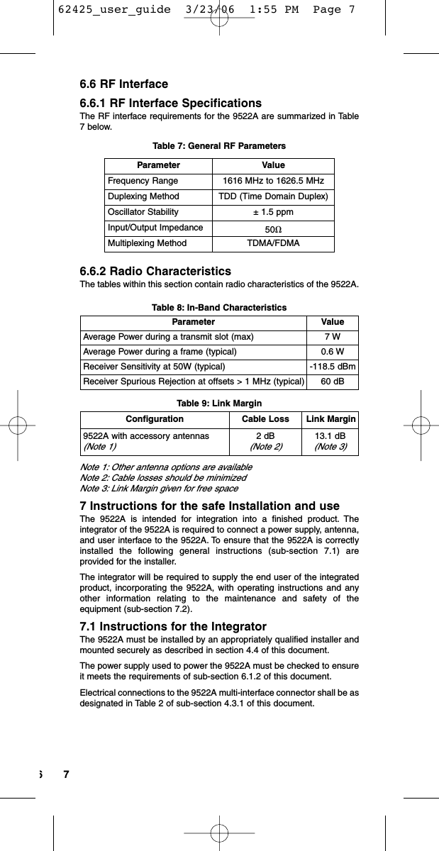
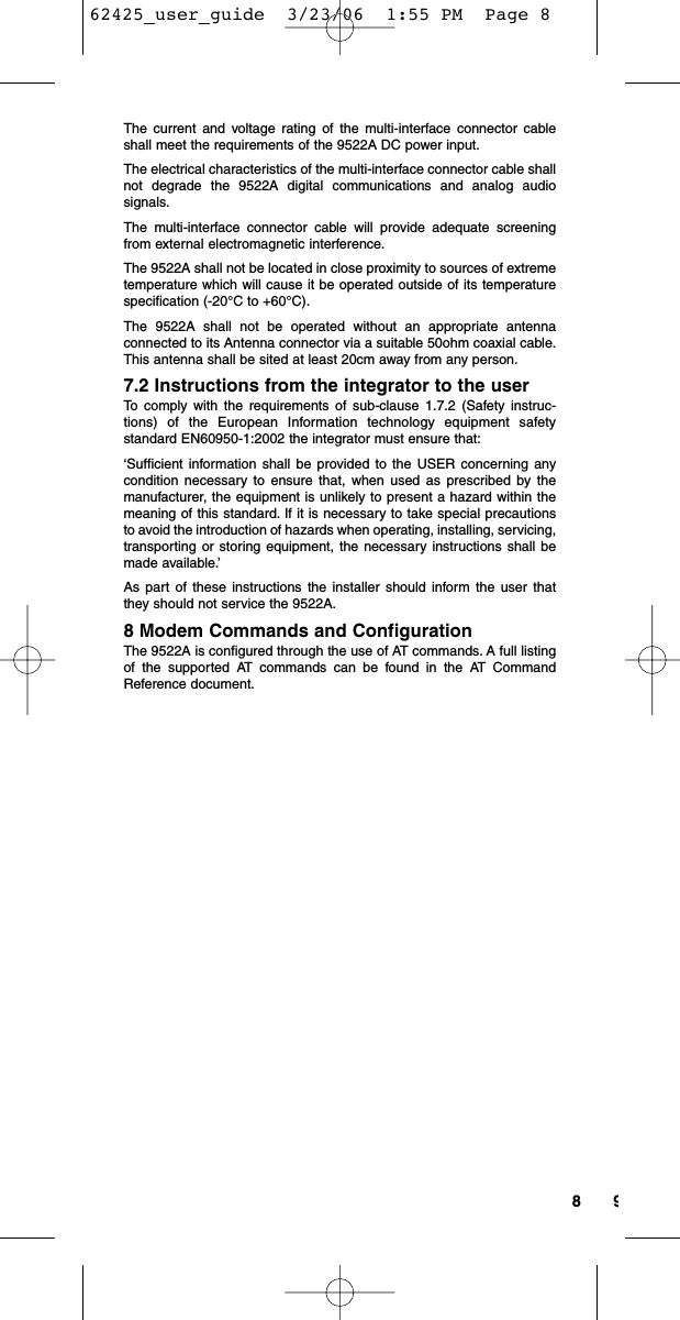
Iridium Satellite 9522AC Satellite L Band Transceiver 9522AC User Manual 62425 user guide

Iridium Satellite LLC Satellite L Band Transceiver 9522AC 62425 user guide

Modified user manual

9522AL-BAND TRANSCEIVERUSER’S GUIDE62425_user_guide  3/23/06  1:55 PM  Page 1
Contents1 Product Overview  . . . . . . . . . . . . . . . . . . .12 Export Compliance Information . . . . . . . .13 Standards Compliance  . . . . . . . . . . . . . . .13.1 FCC Compliance  . . . . . . . . . . . . . . . . .13.2 CE Compliance . . . . . . . . . . . . . . . . . . .14 Physical Specifications  . . . . . . . . . . . . . .24.1 Dimensions  . . . . . . . . . . . . . . . . . . . . . .24.2 Dimensional Views  . . . . . . . . . . . . . . . .24.3 Interface Connectors  . . . . . . . . . . . . . .34.3.1 Multi-Interface Connector  . . . . . . . . .34.3.2 Antenna Connector  . . . . . . . . . . . . . .44.3.3 SIM Chip Reader  . . . . . . . . . . . . . . . .44.4 Mounting  . . . . . . . . . . . . . . . . . . . . . . . .44.5 Connector Sealing in HarshEnvironments  . . . . . . . . . . . . . . . . . . . .55 Environmental  . . . . . . . . . . . . . . . . . . . . . .56 Electrical Interfaces  . . . . . . . . . . . . . . . . .56.1 DC Power Interface . . . . . . . . . . . . . . . .56.1.1 DC Power Interface SignalDescriptions  . . . . . . . . . . . . . . . . . . . .56.1.2 DC Power Input Specifications  . . . . .66.2 Control/Digital Audio (DPL bus) Interface  . . . . . . . . . . . . . . . . . . . . . . . .66.2.1 Control/Digital Audio Interface SignalDescriptions  . . . . . . . . . . . . . . . . . . . .66.3 RS232 Data Interface  . . . . . . . . . . . . . .66.3.1 RS232 Data Signal Descriptions  . . . .662425_user_guide  3/23/06  1:55 PM  Page 2
6.3.2 Autobaud  . . . . . . . . . . . . . . . . . . . . . .66.4 Analog Audio Interface  . . . . . . . . . . . . .66.4.1 Analog Audio Interface SignalDescriptions   . . . . . . . . . . . . . . . . . . .66.5 SIM Interface  . . . . . . . . . . . . . . . . . . . .66.6 RF Interface  . . . . . . . . . . . . . . . . . . . . .76.6.1 RF Interface Specifications  . . . . . . . .76.6.2 Radio Characteristics . . . . . . . . . . . . .77 Instructions for the Safe Installation andUse  . . . . . . . . . . . . . . . . . . . . . . . . . . . . . . .77.1 Instructions for the Integrator  . . . . . . . .77.2 Instructions from the integrator to the user . . . . . . . . . . . . . . . . . . . . . . .88 Modem Commands and Configuration  . .8Iridium Limited Warranty for SatelliteSubscriber Radiotelephone Products  . . . .9Coverage and Duration . . . . . . . . . . . . . . . .9Conditions Not Covered by this Warranty . .9Obtaining Warranty Service  . . . . . . . . . . .10General Provisions  . . . . . . . . . . . . . . . . . .10Conditions of Use and Disclaimer of Liability  . . . . . . . . . . . . . . . .10State Law and Other Jurisdiction Rights:Software Copyrights  . . . . . . . . . . . . . . . . .11Contact  . . . . . . . . . . . . . . . . . . . . . . . . . . .11E C Directive Declaration of Conformity . .1262425_user_guide  3/23/06  1:55 PM  Page 3
11 Product OverviewThe 9522A L-Band Transceiver (9522A) is designed to be integratedinto a specific application with other hardware and software to producea solution designed for a specific application or vertical market. Someexamples of these solutions include a maritime voice telephony terminalor a vehicle tracking solution.The 9522A functionally supports all of Iridium’s voice and data services.Applications can be built to use one or multiple services using the voiceand data interfaces. The 9522A is a functional replacement to the 9522“Sebring” L-Band Transceiver. However it should be noted that there aresome differences to the voice interface.The 9522A is regulatory approved for FCC, Canada, and CE. Thisallows the 9522A to be integrated into a variety of subscriber products,or retrofitted into existing L-Band Transceiver based products. Theseproducts, when integrated together will require Regulatory testing to beconducted by the integrator. Please note that the 9522A is onlyapproved for use with an antenna that has a gain of ≤3 dBi.The 9522A is essentially provided as a ‘black box’ with all interfacesprovided via a DB25 connector. The product provides the core trans-ceiver module and SIM card reader. All other functions and hardwaresuch as keypad, display, power supply, antenna etc. must be providedby the solution developer. The DB25 provides the following interfacesand connections:• Analog Audio• Control / Digital Audio• RS232• Power Input• On / Off2 Export Compliance InformationThis product is controlled by the export laws and regulations of theUnited States of America. The U.S. Government may restrict the exportor re-export of this product to certain individuals and/or destinations. Forfurther information, contact the U.S. Department of Commerce, Bureauof Industry and Security or visit www.bis.doc.gov.3 Standards ComplianceThe 9522A is designed to comply with the standards for RadioEmissions Compliance, Electromagnetic Compatibility, and AC Safety inthe United States, European Union and Canada.3.1 FCC ComplianceThe 9522A is certified under 47 CFR Part 25 as FCC ID:Q639522AC. Italso complies with Parts 2 and 15 of the FCC Regulations. Operation issubject to the condition that this device does not cause harmful interfer-ence. Any changes or modifications, including the use of a non-standardantenna, not expressly approved by the party responsible forcompliance could void the user’s authority to operate the equipment.IMPORTANT:To comply with FCC RF exposure requirements, a min-imum separation of 20 cm is required between the antenna and allpersons.3.2 CE ComplianceThis product complies with the European Community Council Directivefor R&TTE, 99/5/EC, provided that the integrator/user adheres to theinstructions detailed in this 9522A Interface Specification. This productis in compliance with applicable ETSI standards. Compliance with therequirements of ETSI EN 301 489 requires the use of a shielded digitaldata interface cable.62425_user_guide  3/23/06  1:55 PM  Page 1
324 Physical SpecificationsThe 9522A is depicted in Figure 1 below.Figure 1: Top View4.1 DimensionsThe overall dimensions of the 9522A and its weight are summarized inTable 1 below.Table 1: Mechanical Dimensions4.2 Dimensional ViewsDimensioned views of the 9522A are shown in Figures 2-5 to follow.Figure 2: Side ViewParameter ValueLength (including antenna connector) 216.1mm (8.51”)Length (excluding antenna connector) 196.4mm (7.73”)Width 82.6mm (3.25”)Depth 39.0mm (1.54”)Weight (approximate) 659g62425_user_guide  3/23/06  1:55 PM  Page 2
324.3 Interface ConnectorsThe 9522A incorporates three interface connectors.• Multi-Interface Connector (located on the end of the 9522A)• Antenna Connector (located on the end of the 9522A; opposite tothe multi-interface connector)• Subscriber Identity Module (SIM) Chip Connector (locatedbeneath a cover plate atop the 9522A)4.3.1 Multi-Interface ConnectorThe multi-interface connector is a 25 pin D-subminiature type thatincludes four interfaces.• DC Power• Control/Digital Audio (DPL bus)• RS232 Data• Analog AudioThe pin out information for this connector is given in Table 2 below.Figure 3: Bottom ViewFigure 4: Antenna Connector End ViewFigure 5: Multi-Interface Connector End View62425_user_guide  3/23/06  1:55 PM  Page 3
54Table 2: 25-way connector pin-out4.3.2 Antenna ConnectorThe 9522A provides a single 50ȉ, TNC type antenna connector bothtransmit and receive.4.3.3 SIM Chip ReaderAn integrated SIM chip reader is provided on the 9522A. This connectorallows installation of the chip form of the SIM beneath a cover plate onthe 9522A housing.4.4 MountingThe 9522A incorporates (6) mounting holes on its bottom surface thatcan aid in its mounting. See Figure 3 for locations of these features. It isrecommended that a thread-forming screw be used to mount the 9522Avia these features. Particularly, a Textron Camcar® Taptite® II Thread-Rolling Fastener of M3.5x0.6 thread type is recommended. This fastenerhas a 15IP Torx Plus® pan head and is available in lengths of 6, 8, 12,16, and 20 mm as part number 3BE-P802-00, 3BE-P803-00, 3BE-P8185-00, 3BE-P804-00, 3BEP8186-00, and 3BE-P8187-00respectively. Length should be chosen to ensure that penetration intothe 9522A housing does not exceed 11 mm.If a 6-32 thread type is desired, a Textron Camcar® Taptite® II Thread-Rolling Fastener with a 15IP Torx Plus® pan head is available in lengthsof 1/4, 5/16, 3/8, 1/2, 5/8, 3/4, and 1 inch as part number 3BE-P814-00,3BE-P8123-00, 3BE-P815-00, 3BE-P816-00, 3BE-P8124-00, 3BE-P817-00, and 3BE-P818-00 respectively. A 10IP Torx Plus® flat headversion is also available in a single length of 1/2 inch as part number3BE-P801-00. Another 6-32 thread type option is to insert a helical coilinsert with a 6-32 internal thread into these features thusaccommodating 6-32 threaded fasteners as mounting hardware for the9522A. National Aerospace Standard NASM122238 serves as atechnical reference for the recommended helical coil insert.Contact Signal Description1EXT_ON_OFF External connection for On / Off key input to 9522A2EXT_11HZ 90ms “frame sync” signal (used in testing)3EXT_GND Power Ground input to 9522A4EXT_PWR Power input to 9522A5SPKR_AUD Speaker audio output from 9522A6DA_TX PCM digital audio output from 9522A7DF_RI Data / Fax Ring Indication output from 9522A8DF_RTS Data / Fax Request to Send input to 9522A9DF_S_TX Data / Fax (UART) data input to 9522A10 DF_DCD Data / Fax Data Carrier Detect output from 9522A11 DA_FS PCM digital audio frame sync output from 9522A12 DA_CLK PCM digital 2.048MHz audio clock output from 9522A13 DF_S_RX Data / Fax data (UART) output from 9522A14 0V Signal ground, 0V signal reference and return15 MIC _AUD Microphone audio input to 9522A16 EXT_PWR Power input to 9522A17 EXT_GND Power Ground input to 9522A18 DPL_TX Digital Peripheral Link (UART) data output from 9522A19 DF_DTR Data / Fax Data Terminal Ready input to 9522A20* DPL_RX Digital Peripheral Link (UART) data input to 9522A21 DF_DSR Data / Fax Data Set Ready output from 9522A22 DF_CTS Data / Fax Clear to Send output from 9522A23 0V Signal ground, 0V signal reference and return24 DA_RX PCM digital audio input to 9522A25 0V Signal ground, 0V signal reference and return62425_user_guide  3/23/06  1:55 PM  Page 4
544.5 Connector Sealing in Harsh EnvironmentsIf the 9522A is to be used in a harsh environment with exposure to highhumidity or water, the mating of the multi-interface connector must befurther sealed to protect from moisture entry. It is recommended that abead of RTV silicone sealant be placed on the connector mating to the9522A’s multi-interface connector where shown in Figure 6 below. Amaterial similar to Permatex 16B should be used.Figure 6: Place a bead of Silicone RTV material along this area allaround the connector mating to the 9522A’s multi-interface connector.5 EnvironmentalThe environmental specifications of the 9522A are summarized in Table3 below.Table 3: Environmental Specifications6 Electrical InterfacesThe subsections to follow contain interface information for the electricalinterfaces of the 9522A.6.1 DC Power Interface6.1.1 DC Power Interface Signal DescriptionsThe DC power interface is comprised of the DC power inputs and acontrol signal as summarized in Table 4 below. The EXT_PWR andGND inputs are used to supply DC power to the 9522A. TheEXT_ON_OFF control input is pulled to a GND level to toggle the 9522Aon and off. Note that both pairs of pins should be connected for EXTPWR and EXT GND.Table 4: Control/Audio Interface Signal DescriptionsSignal Name Signal DescriptionEXT_PWR (pin 4 and 16) External power +4.4VDC inputEXT_GND (pin 3 and 17) External power GND inputEXT_ON_OFF (pin 1) Power on/off control inputParameter ValueOperating Temperature Range -20°C to + 60°COperating Humidity Range ≤75% RHStorage Temperature Range -40°C to + 85°CStorage Humidity Range ≤93% R62425_user_guide  3/23/06  1:55 PM  Page 5
766.1.2 DC Power Input SpecificationsThe DC power requirements for the 9522A are summarized in Table 5below. Note that these requirements apply to DC power measured at the9522A multi-interface connector input.Table 5: DC Power Input Specifications6.2 Control/Digital Audio (DPL bus) Interface6.2.1 Control/Digital Audio Interface SignalDescriptionsThe control/digital audio interface enables peripherals such as handsetsand SIM card readers to be interfaced to the 9522A. The interfaceutilizes an Iridium proprietary communication bus not detailed in this factsheet. Details can be made available after appropriate Non-disclosureAgreements and /or License Agreements are executed.6.3 RS232 Data Interface6.3.1 RS232 Data Signal DescriptionsThe RS232 data interface is comprised of eight standard RS232 data,control, and status signals plus a ground level signal reference. Thisinterface allows a connected Data Terminal Equipment (DTE) to utilizethe 9522A’s modem functionality via AT command control. A 3-wireRS232 Data minimal interface may also be implemented however the 9wire interface offers better control and is the recommendedimplementation.6.3.2 AutobaudThe 9522A default is for autobaud to be enabled. Autobaud will occur onthe following characters ‘a’, ‘A’, CR (carriage return). Autobaud will alsooccur on the escape sequence character, provided this is an oddnumber character. Normally this is set to ‘+’ in register S2 see ATCommand Reference for details.6.4 Analog Audio Interface6.4.1 Analog Audio Interface Signal DescriptionsThe analog audio interface is comprised of the analog audio input andoutput signals referenced to the 0V signal ground as summarized inTable 6 below.Table 6: Analog Audio Interface Signal Descriptions6.5 SIM InterfaceAn integrated SIM chip reader is provided on the 9522A. An externalSIM card reader may also be interfaced as a peripheral to the 9522A viathe DPL bus (control/audio interface). A SIM card in the external readerwill take precedence over the SIM chip in the integrated connector whenboth are present.Parameter ValueMain Input Voltage - Range +4.0 VDC to +4.8 VDCMain Input Voltage – Nominal 4.4VDCMain Input Voltage – Ripple 40 mVppPeak Input Current (maximum) 2.5 A @ 4.4 VDCMain Input Active Power (average) 2200 mWMain Input Standby Power (average) 570 mWSignal Name Signal DescriptionMIC_AUD (pin 15) Analog audio input to 9522ASPKR_AUD (pin 5) Analog audio output from 9522A0V (pin 14, 23 and 25) Signal ground62425_user_guide  3/23/06  1:55 PM  Page 6
766.6 RF Interface6.6.1 RF Interface SpecificationsThe RF interface requirements for the 9522A are summarized in Table7 below.Table 7: General RF Parameters6.6.2 Radio CharacteristicsThe tables within this section contain radio characteristics of the 9522A.Table 8: In-Band CharacteristicsTable 9: Link MarginNote 1: Other antenna options are available Note 2: Cable losses should be minimized Note 3: Link Margin given for free space7 Instructions for the safe Installation and useThe 9522A is intended for integration into a finished product. Theintegrator of the 9522A is required to connect a power supply, antenna,and user interface to the 9522A. To ensure that the 9522A is correctlyinstalled the following general instructions (sub-section 7.1) areprovided for the installer.The integrator will be required to supply the end user of the integratedproduct, incorporating the 9522A, with operating instructions and anyother information relating to the maintenance and safety of theequipment (sub-section 7.2).7.1 Instructions for the IntegratorThe 9522A must be installed by an appropriately qualified installer andmounted securely as described in section 4.4 of this document.The power supply used to power the 9522A must be checked to ensureit meets the requirements of sub-section 6.1.2 of this document.Electrical connections to the 9522A multi-interface connector shall be asdesignated in Table 2 of sub-section 4.3.1 of this document.Parameter ValueAverage Power during a transmit slot (max) 7 WAverage Power during a frame (typical) 0.6 WReceiver Sensitivity at 50W (typical) -118.5 dBmReceiver Spurious Rejection at offsets > 1 MHz (typical) 60 dBParameter ValueFrequency Range 1616 MHz to 1626.5 MHzDuplexing Method TDD (Time Domain Duplex)Oscillator Stability ± 1.5 ppmInput/Output Impedance 50ȉMultiplexing Method TDMA/FDMAConfiguration Cable Loss Link Margin9522A with accessory antennas(Note 1)2 dB (Note 2)13.1 dB (Note 3)62425_user_guide  3/23/06  1:55 PM  Page 7
98The current and voltage rating of the multi-interface connector cableshall meet the requirements of the 9522A DC power input.The electrical characteristics of the multi-interface connector cable shallnot degrade the 9522A digital communications and analog audiosignals.The multi-interface connector cable will provide adequate screeningfrom external electromagnetic interference.The 9522A shall not be located in close proximity to sources of extremetemperature which will cause it be operated outside of its temperaturespecification (-20°C to +60°C).The 9522A shall not be operated without an appropriate antennaconnected to its Antenna connector via a suitable 50ohm coaxial cable.This antenna shall be sited at least 20cm away from any person.7.2 Instructions from the integrator to the userTo comply with the requirements of sub-clause 1.7.2 (Safety instruc-tions) of the European Information technology equipment safetystandard EN60950-1:2002 the integrator must ensure that:‘Sufficient information shall be provided to the USER concerning anycondition necessary to ensure that, when used as prescribed by themanufacturer, the equipment is unlikely to present a hazard within themeaning of this standard. If it is necessary to take special precautionsto avoid the introduction of hazards when operating, installing, servicing,transporting or storing equipment, the necessary instructions shall bemade available.’As part of these instructions the installer should inform the user thatthey should not service the 9522A.8 Modem Commands and ConfigurationThe 9522A is configured through the use of AT commands. A full listingof the supported AT commands can be found in the AT CommandReference document.62425_user_guide  3/23/06  1:55 PM  Page 8
98Iridium Limited Warranty For Satellite SubscriberRadiotelephone Products1. Coverage and DurationIridium warrants that its new satellite subscriber radiotelephoneproducts and accessories (the “Product”) shall be free from defects inmaterials and workmanship for a period of twelve (12) months from thedate such Product is delivered to the first end user purchaser or firstlessee (the “Purchaser”), or the date such Products are first placed intosatellite subscriber service, whichever occurs earliest.Iridium, at its option, shall at no charge to Purchaser, either repair orreplace the Product, or refund the purchase price of a Product that doesnot conform to this warranty, provided the Product is returned inaccordance with the instructions set out below and within the warrantyperiod. These remedies are Purchaser’s exclusive remedies under thiswarranty. Repair may include the replacement of parts or boards withfunctionally equivalent reconditioned or new parts or boards. A productthat has been repaired or replaced is warranted for the balance of theoriginal warranty period. A Product for which a replacement has beenprovided shall become Iridium’s property.This warranty is made by Iridium to the Purchaser of the Products only,and it is not assignable or transferable by the Purchaser. This is Iridium’ssole and complete warranty for the Products. Iridium assumes noobligation or liability for additions or modifications to this warranty unlessmade in writing and signed by an officer of Iridium. Iridium does notwarrant any installation, maintenance, or service of the Products notperformed by Iridium.This Product is covered by a U.S.A. warranty. If the Product has beensold outside of the U.S.A., Iridium will honor the U.S.A. warranty termsand conditions only. Outside of the U.S.A., any different warranty terms,liabilities and/or legal requirements of the country in which the Productis sold are specifically disclaimed by Iridium.2. Conditions Not Covered By This Warrantya. Products that are integrated, installed, maintained, or serviced in anymanner other than in accordance with the Iridium user documentationfurnished with or applicable to the Product.b. Product damage caused by the use of ancillary equipment not furnishedIridium, including accessories and peripherals.c. Problems where the Product is used in a combination with ancillaryequipment not furnished by Iridium, and it is determined by Iridium there isno fault with the Product.d. Ancillary equipment not furnished by Iridium which is attached to or usedin connection with the Products is not the responsibility of Iridium, and allsuch equipment is expressly excluded from this warranty. Furthermore,Iridium does not warrant the integrated operation of the combination of theProducts with any ancillary equipment not furnished by Iridium.e. Defects or damage resulting from: use of the Product in any manner notnormal or customary; misuse, accident or neglect including but not limited todropping the Product onto hard surfaces, immersion in or exposure to water,rain or extreme humidity, immersion in or exposure to sand, dirt or otherparticulates, exposure to extreme heat, spills of food or liquid; impropertesting, operation, maintenance, installation, adjustment; or any alteration ormodification of any kind.f. Batteries manufactured by Iridium and sold with Products whose capacityexceeds 80% of rated capacity are not covered. Batteries whose capacityfalls below 80% of rated capacity, or that develop leakage, shall beconsidered nonconforming. This warranty is voided for batteries if: a) suchbatteries are charged by other than the Iridium-approved battery chargerspecified for charging such batteries; b) any seals on such batteries are62425_user_guide  3/23/06  1:55 PM  Page 9
110broken or show evidence of tampering; or c) such batteries are used inequipment other than the Product for which they are specified; or d) suchbatteries are charged and stored at temperatures greater than 60 degreescentigrade.g. Breakage or damage to antennas, or scratches or other damage to plasticsurfaces or other externally exposed parts caused by Purchaser’s use.h. Products disassembled or repaired in such a manner as to adverselyaffect performance or prevent adequate inspection and testing to verify anywarranty claim.i. Products on which serial numbers or date tags have been removed, alteredor obliterated.j. Coil cords that are stretched or on which the modular tab is broken; leathercases, which are covered under separate manufacturers’ warranties;k. Products rented on a month-to-month basis.l. Normal wear and tear.3. Obtaining Warranty ServiceFor warranty questions, repairs, or for the return of Product, please callyour Service Provider or Point-of-Sale, not Iridium. Equipmentneeding service should be returned to your Service Provider or Point-of-Sale, not Iridium.SERVICE WORK PERFORMED BY SERVICE CENTERS NOTAUTHORIZED BY IRIDIUM TO PERFORM SUCH WORK WILL VOIDTHIS WARRANTY.All Products shipped to Iridium’s authorized Warranty Service Center mustbe shipped with freight and insurance prepaid. Purchaser must includewith the Product a bill of sale, a lease, or some other comparable proof ofpurchase, the name and location of the installation facility, if any, and mostimportantly, the Purchaser’s name, address, and telephone number and awritten description of the problem. Product that is repaired or replacedunder this warranty shall be returned to Purchaser at Iridium’s expense forthe freight and insurance, and at Purchaser’s expense for any applicableduties or other charges. If additional information is needed, please contactIridium at the address and phone number listed in Paragraph 7 below.4. General ProvisionsTHIS WARRANTY IS GIVEN IN LIEU OF ALL OTHER WARRANTIESEXPRESS OR IMPLIED, INCLUDING BUT NOT LIMITED TO THEIMPLIED WARRANTIES OF MERCHANTABILITY AND FITNESS FORA PARTICULAR PURPOSE. FURTHER, THIS WARRANTY COVERSTHE PRODUCTS ONLY, AND NO WARRANTY IS MADE AS TO COV-ERAGE, AVAILABILITY, OR GRADE OF SERVICE PROVIDED BYIRIDIUM SEPARATELY FOR IRIDIUM SATELLITE SERVICES. IN NOEVENT SHALL IRIDIUM BE LIABLE FOR DAMAGES IN EXCESS OFTHE PURCHASE PRICE OF THE PRODUCT IN QUESTION, OR FORANY LOSS OF USE, LOSS OF TIME, INCONVENIENCE, COMMER-CIAL LOSS, LOST PROFITS OR SAVINGS OR OTHER INCIDENTAL,SPECIAL, OR CONSEQUENTIAL DAMAGES ARISING OUT OF THEUSE OR INABILITY TO USE SUCH PRODUCT, TO THE FULLEXTENT SUCH MAY BE DISCLAIMED BY LAW.5. Conditions of Use and Disclaimer of LiabilityIN THE UNITED STATES, AND SUBJECT TO AVAILABILITY, CALLSTO 911 OR 112 ARE ROUTED TO AN EMERGENCY CALL CENTERFOR RESPONSE. OUTSIDE THE UNITED STATES, CALLS TO 911OR 112, OR OTHER EMERGENCY ACCESS NUMBERS SUCH AS999, ARE NOT AVAILABLE ON THE IRIDIUM SYSTEM. THE IRIDIUMSERVICE DOES NOT CURRENTLY PROVIDE ENHANCED 911 ORENHANCED 112 SERVICE, WHICH AUTOMATICALLY IDENTIFIESCALLER LOCATION. CALLER LOCATION IDENTIFICATION IS NOTAUTOMATICALLY TRANSMITTED ON THE IRIDIUM SYSTEM.62425_user_guide  3/23/06  1:55 PM  Page 10
110Users of the Iridium Satellite LLC (“Iridium”) mobile satellite phone serviceand related equipment, including without limitation those using the phoneservice and equipment in any manner in conjunction with emergency 911or emergency 112 or any other distress calling or emergency services, bothpublic of privately operated, acknowledge and agree as a condition of theprovision of phone service and equipment by Iridium that they will make noclaim, whether in contract, tort or otherwise, against Iridium for bodily injury,loss of life, damage to property or for any other loss whatsoever, or forspecial, incidental, indirect, consequential or punitive damages, by reasonof any unavailability, delay, faultiness or failures of the Iridium facilities orphone service or equipment or for inaccuracies or failures with regard to anyuser information provided. This is a waiver and release and disclaimer ofliability to the fullest extent permitted by applicable law and appliesregardless of the cause of any liability, including without limitations, towrongful conduct, omission or fault of employees or agents of Iridium.Iridium makes no warranties, express or implied, including any impliedwarranty of merchantability or fitness for a particular purpose concerningIridium service or equipment. Iridium cannot promise uninterrupted or errorfree service.Users by their use of the phone service and equipment consent to Iridium’sdisclosure of user information, including but not limited to name, address,telephone number and location information, including, when available, thegeographic coordinates of equipment, to governmental and quasi-governmental agencies, where Iridium deems it necessary in its solediscretion to respond to an exigent circumstance. These governmental andquasi-governmental agencies shall be deemed “users” for all purposes ofthis Disclaimer of Liability.6. State Law and Other Jurisdiction Rights;Software CopyrightsSOME STATES AND OTHER JURISDICTIONS DO NOT ALLOW THEEXCLUSION OR LIMITATION OF INCIDENTAL OR CONSEQUENTIALDAMAGES, OR LIMITATION ON HOW LONG AN IMPLIED WARRANTYLASTS, SO THE ABOVE LIMITATIONS OR EXCLUSIONS MAY NOTAPPLY TO PURCHASER.This warranty gives Purchaser specific legal rights, and Purchaser mayalso have other rights which vary from jurisdiction to jurisdiction.Laws in the United States and other countries preserve for Iridiumcertain exclusive rights for copyrighted Product software such as theexclusive rights to reproduce in copies and distribute copies of suchProduct software. Product software may be copied into, used in andredistributed with only the Product associated with such Productsoftware. No other use, including without limitation disassembly, of suchProduct software or exercise of exclusive rights in such Productsoftware is permitted.7. ContactFor additional information about this Product warranty, please contactyour Service Provider or Point of Sale.For additional information about Iridium products and services, pleasecontact Iridium as follows:By Telephone: Customer Service Toll Free from a landline:+1-866-947-4348 Local or International Number:+1-480-752-5155By Email: Info@iridium.comBy Mail: Iridium Satellite LLCAttn: Customer Service8440 S. River Parkway, Tempe, AZ 85284 USA62425_user_guide  3/23/06  1:55 PM  Page 11
12E C DirectiveDeclaration of Conformity62425_user_guide  3/23/06  1:55 PM  Page 12
2Iridium Satellite LLC Headquarters6701 Democracy Blvd., Suite 500Bethesda, MD 20817 USAPhone +1.301.571.6200Fax +1.301.571.6250Iridium Satellite LLC8440 S. River ParkwayTempe, AZ 85284Toll Free from a landline +1.866.947.4348Local or International +1.480.752.5155Fax +1.480.752.1105email info@iridium.comwww.iridium.comLUG060162425_user_guide  3/23/06  1:55 PM  Page 13

Navigation menu