Iridium Satellite 9522AC Satellite L Band Transceiver 9522AC User Manual 62425 user guide
Iridium Satellite LLC Satellite L Band Transceiver 9522AC 62425 user guide
Modified user manual
9522A
L-BAND TRANSCEIVER
USER’S GUIDE
62425_user_guide 3/23/06 1:55 PM Page 1

Contents
1 Product Overview . . . . . . . . . . . . . . . . . . .1
2 Export Compliance Information . . . . . . . .1
3 Standards Compliance . . . . . . . . . . . . . . .1
3.1 FCC Compliance . . . . . . . . . . . . . . . . .1
3.2 CE Compliance . . . . . . . . . . . . . . . . . . .1
4 Physical Specifications . . . . . . . . . . . . . .2
4.1 Dimensions . . . . . . . . . . . . . . . . . . . . . .2
4.2 Dimensional Views . . . . . . . . . . . . . . . .2
4.3 Interface Connectors . . . . . . . . . . . . . .3
4.3.1 Multi-Interface Connector . . . . . . . . .3
4.3.2 Antenna Connector . . . . . . . . . . . . . .4
4.3.3 SIM Chip Reader . . . . . . . . . . . . . . . .4
4.4 Mounting . . . . . . . . . . . . . . . . . . . . . . . .4
4.5 Connector Sealing in Harsh
Environments . . . . . . . . . . . . . . . . . . . .5
5 Environmental . . . . . . . . . . . . . . . . . . . . . .5
6 Electrical Interfaces . . . . . . . . . . . . . . . . .5
6.1 DC Power Interface . . . . . . . . . . . . . . . .5
6.1.1 DC Power Interface Signal
Descriptions . . . . . . . . . . . . . . . . . . . .5
6.1.2 DC Power Input Specifications . . . . .6
6.2 Control/Digital Audio (DPL bus)
Interface . . . . . . . . . . . . . . . . . . . . . . . .6
6.2.1 Control/Digital Audio Interface Signal
Descriptions . . . . . . . . . . . . . . . . . . . .6
6.3 RS232 Data Interface . . . . . . . . . . . . . .6
6.3.1 RS232 Data Signal Descriptions . . . .6
62425_user_guide 3/23/06 1:55 PM Page 2

6.3.2 Autobaud . . . . . . . . . . . . . . . . . . . . . .6
6.4 Analog Audio Interface . . . . . . . . . . . . .6
6.4.1 Analog Audio Interface Signal
Descriptions . . . . . . . . . . . . . . . . . . .6
6.5 SIM Interface . . . . . . . . . . . . . . . . . . . .6
6.6 RF Interface . . . . . . . . . . . . . . . . . . . . .7
6.6.1 RF Interface Specifications . . . . . . . .7
6.6.2 Radio Characteristics . . . . . . . . . . . . .7
7 Instructions for the Safe Installation and
Use . . . . . . . . . . . . . . . . . . . . . . . . . . . . . . .7
7.1 Instructions for the Integrator . . . . . . . .7
7.2 Instructions from the integrator
to the user . . . . . . . . . . . . . . . . . . . . . . .8
8 Modem Commands and Configuration . .8
Iridium Limited Warranty for Satellite
Subscriber Radiotelephone Products . . . .9
Coverage and Duration . . . . . . . . . . . . . . . .9
Conditions Not Covered by this Warranty . .9
Obtaining Warranty Service . . . . . . . . . . .10
General Provisions . . . . . . . . . . . . . . . . . .10
Conditions of Use and
Disclaimer of Liability . . . . . . . . . . . . . . . .10
State Law and Other Jurisdiction Rights:
Software Copyrights . . . . . . . . . . . . . . . . .11
Contact . . . . . . . . . . . . . . . . . . . . . . . . . . .11
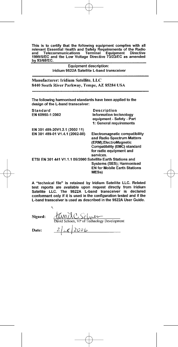
E C Directive Declaration of Conformity . .12
62425_user_guide 3/23/06 1:55 PM Page 3

1
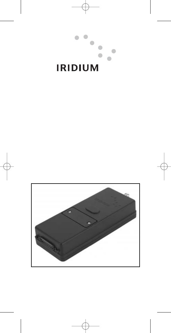
1 Product Overview
The 9522A L-Band Transceiver (9522A) is designed to be integrated
into a specific application with other hardware and software to produce
a solution designed for a specific application or vertical market. Some
examples of these solutions include a maritime voice telephony terminal
or a vehicle tracking solution.
The 9522A functionally supports all of Iridium’s voice and data services.
Applications can be built to use one or multiple services using the voice
and data interfaces. The 9522A is a functional replacement to the 9522
“Sebring” L-Band Transceiver. However it should be noted that there are
some differences to the voice interface.
The 9522A is regulatory approved for FCC, Canada, and CE. This
allows the 9522A to be integrated into a variety of subscriber products,
or retrofitted into existing L-Band Transceiver based products. These
products, when integrated together will require Regulatory testing to be
conducted by the integrator. Please note that the 9522A is only
approved for use with an antenna that has a gain of ≤3 dBi.
The 9522A is essentially provided as a ‘black box’ with all interfaces
provided via a DB25 connector. The product provides the core trans-
ceiver module and SIM card reader. All other functions and hardware
such as keypad, display, power supply, antenna etc. must be provided
by the solution developer. The DB25 provides the following interfaces
and connections:
• Analog Audio
• Control / Digital Audio
• RS232
• Power Input
• On / Off
2 Export Compliance Information
This product is controlled by the export laws and regulations of the
United States of America. The U.S. Government may restrict the export
or re-export of this product to certain individuals and/or destinations. For
further information, contact the U.S. Department of Commerce, Bureau
of Industry and Security or visit www.bis.doc.gov.
3 Standards Compliance
The 9522A is designed to comply with the standards for Radio
Emissions Compliance, Electromagnetic Compatibility, and AC Safety in
the United States, European Union and Canada.
3.1 FCC Compliance
The 9522A is certified under 47 CFR Part 25 as FCC ID:Q639522AC. It
also complies with Parts 2 and 15 of the FCC Regulations. Operation is
subject to the condition that this device does not cause harmful interfer-
ence. Any changes or modifications, including the use of a non-standard
antenna, not expressly approved by the party responsible for
compliance could void the user’s authority to operate the equipment.
IMPORTANT:
To comply with FCC RF exposure requirements, a min-
imum separation of 20 cm is required between the antenna and all
persons.
3.2 CE Compliance
This product complies with the European Community Council Directive
for R&TTE, 99/5/EC, provided that the integrator/user adheres to the
instructions detailed in this 9522A Interface Specification. This product
is in compliance with applicable ETSI standards. Compliance with the
requirements of ETSI EN 301 489 requires the use of a shielded digital
data interface cable.
62425_user_guide 3/23/06 1:55 PM Page 1
32
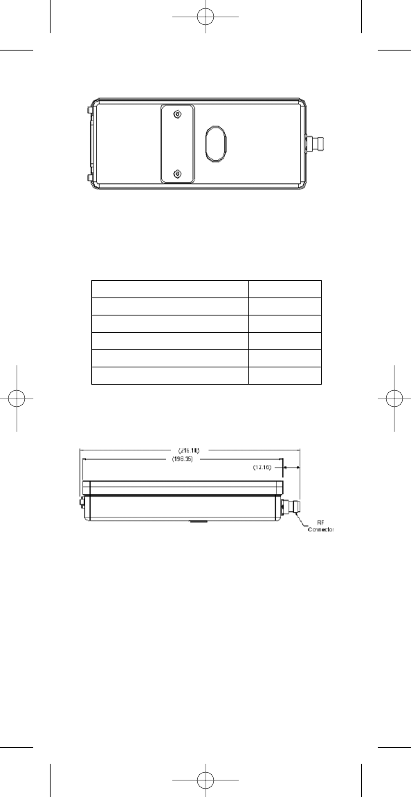
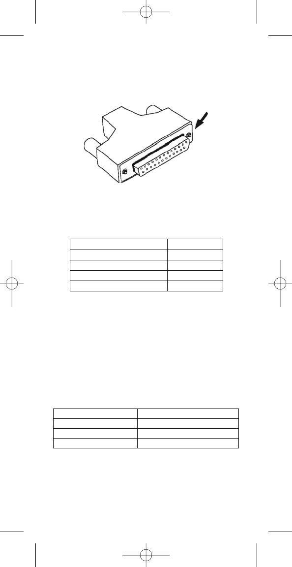
4 Physical Specifications
The 9522A is depicted in Figure 1 below.
Figure 1: Top View
4.1 Dimensions
The overall dimensions of the 9522A and its weight are summarized in
Table 1 below.
Table 1: Mechanical Dimensions
4.2 Dimensional Views
Dimensioned views of the 9522A are shown in Figures 2-5 to follow.
Figure 2: Side View
Parameter Value
Length (including antenna connector) 216.1mm (8.51”)
Length (excluding antenna connector) 196.4mm (7.73”)
Width 82.6mm (3.25”)
Depth 39.0mm (1.54”)
Weight (approximate) 659g
62425_user_guide 3/23/06 1:55 PM Page 2
32
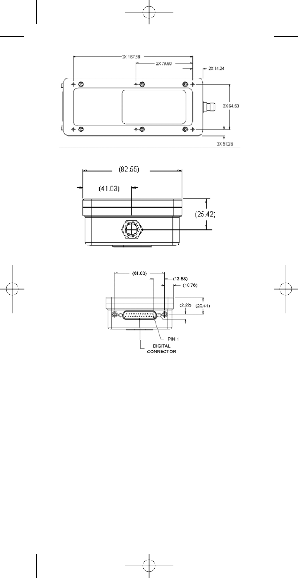
4.3 Interface Connectors
The 9522A incorporates three interface connectors.
• Multi-Interface Connector (located on the end of the 9522A)
• Antenna Connector (located on the end of the 9522A; opposite to
the multi-interface connector)
• Subscriber Identity Module (SIM) Chip Connector (located
beneath a cover plate atop the 9522A)
4.3.1 Multi-Interface Connector
The multi-interface connector is a 25 pin D-subminiature type that
includes four interfaces.
• DC Power
• Control/Digital Audio (DPL bus)
• RS232 Data
• Analog Audio
The pin out information for this connector is given in Table 2 below.
Figure 3: Bottom View
Figure 4: Antenna Connector End View
Figure 5: Multi-Interface Connector End View
62425_user_guide 3/23/06 1:55 PM Page 3
54
Table 2: 25-way connector pin-out
4.3.2 Antenna Connector
The 9522A provides a single 50ȉ, TNC type antenna connector both
transmit and receive.
4.3.3 SIM Chip Reader
An integrated SIM chip reader is provided on the 9522A. This connector
allows installation of the chip form of the SIM beneath a cover plate on
the 9522A housing.
4.4 Mounting
The 9522A incorporates (6) mounting holes on its bottom surface that
can aid in its mounting. See Figure 3 for locations of these features. It is
recommended that a thread-forming screw be used to mount the 9522A
via these features. Particularly, a Textron Camcar® Taptite® II Thread-
Rolling Fastener of M3.5x0.6 thread type is recommended. This fastener
has a 15IP Torx Plus® pan head and is available in lengths of 6, 8, 12,
16, and 20 mm as part number 3BE-P802-00, 3BE-P803-00, 3BE-
P8185-00, 3BE-P804-00, 3BEP8186-00, and 3BE-P8187-00
respectively. Length should be chosen to ensure that penetration into
the 9522A housing does not exceed 11 mm.
If a 6-32 thread type is desired, a Textron Camcar® Taptite® II Thread-
Rolling Fastener with a 15IP Torx Plus® pan head is available in lengths
of 1/4, 5/16, 3/8, 1/2, 5/8, 3/4, and 1 inch as part number 3BE-P814-00,
3BE-P8123-00, 3BE-P815-00, 3BE-P816-00, 3BE-P8124-00, 3BE-
P817-00, and 3BE-P818-00 respectively. A 10IP Torx Plus® flat head
version is also available in a single length of 1/2 inch as part number
3BE-P801-00. Another 6-32 thread type option is to insert a helical coil
insert with a 6-32 internal thread into these features thus
accommodating 6-32 threaded fasteners as mounting hardware for the
9522A. National Aerospace Standard NASM122238 serves as a
technical reference for the recommended helical coil insert.
Contact Signal Description
1EXT_ON_OFF External connection for On / Off key input to 9522A
2EXT_11HZ 90ms “frame sync” signal (used in testing)
3EXT_GND Power Ground input to 9522A
4EXT_PWR Power input to 9522A
5SPKR_AUD Speaker audio output from 9522A
6DA_TX PCM digital audio output from 9522A
7DF_RI Data / Fax Ring Indication output from 9522A
8DF_RTS Data / Fax Request to Send input to 9522A
9DF_S_TX Data / Fax (UART) data input to 9522A
10 DF_DCD Data / Fax Data Carrier Detect output from 9522A
11 DA_FS PCM digital audio frame sync output from 9522A
12 DA_CLK PCM digital 2.048MHz audio clock output from 9522A
13 DF_S_RX Data / Fax data (UART) output from 9522A
14 0V Signal ground, 0V signal reference and return
15 MIC _AUD Microphone audio input to 9522A
16 EXT_PWR Power input to 9522A
17 EXT_GND Power Ground input to 9522A
18 DPL_TX Digital Peripheral Link (UART) data output from 9522A
19 DF_DTR Data / Fax Data Terminal Ready input to 9522A
20* DPL_RX Digital Peripheral Link (UART) data input to 9522A
21 DF_DSR Data / Fax Data Set Ready output from 9522A
22 DF_CTS Data / Fax Clear to Send output from 9522A
23 0V Signal ground, 0V signal reference and return
24 DA_RX PCM digital audio input to 9522A
25 0V Signal ground, 0V signal reference and return
62425_user_guide 3/23/06 1:55 PM Page 4
54
4.5 Connector Sealing in Harsh Environments
If the 9522A is to be used in a harsh environment with exposure to high
humidity or water, the mating of the multi-interface connector must be
further sealed to protect from moisture entry. It is recommended that a
bead of RTV silicone sealant be placed on the connector mating to the
9522A’s multi-interface connector where shown in Figure 6 below. A
material similar to Permatex 16B should be used.
Figure 6: Place a bead of Silicone RTV material along this area all
around the connector mating to the 9522A’s multi-interface connector.
5 Environmental
The environmental specifications of the 9522A are summarized in Table
3 below.
Table 3: Environmental Specifications
6 Electrical Interfaces
The subsections to follow contain interface information for the electrical
interfaces of the 9522A.
6.1 DC Power Interface
6.1.1 DC Power Interface Signal Descriptions
The DC power interface is comprised of the DC power inputs and a
control signal as summarized in Table 4 below. The EXT_PWR and
GND inputs are used to supply DC power to the 9522A. The
EXT_ON_OFF control input is pulled to a GND level to toggle the 9522A
on and off. Note that both pairs of pins should be connected for EXT
PWR and EXT GND.
Table 4: Control/Audio Interface Signal Descriptions
Signal Name Signal Description
EXT_PWR (pin 4 and 16) External power +4.4VDC input
EXT_GND (pin 3 and 17) External power GND input
EXT_ON_OFF (pin 1) Power on/off control input
Parameter Value
Operating Temperature Range -20°C to + 60°C
Operating Humidity Range ≤75% RH
Storage Temperature Range -40°C to + 85°C
Storage Humidity Range ≤93% R
62425_user_guide 3/23/06 1:55 PM Page 5
76
6.1.2 DC Power Input Specifications
The DC power requirements for the 9522A are summarized in Table 5
below. Note that these requirements apply to DC power measured at the
9522A multi-interface connector input.
Table 5: DC Power Input Specifications
6.2 Control/Digital Audio (DPL bus) Interface
6.2.1 Control/Digital Audio Interface Signal
Descriptions
The control/digital audio interface enables peripherals such as handsets
and SIM card readers to be interfaced to the 9522A. The interface
utilizes an Iridium proprietary communication bus not detailed in this fact
sheet. Details can be made available after appropriate Non-disclosure
Agreements and /or License Agreements are executed.
6.3 RS232 Data Interface
6.3.1 RS232 Data Signal Descriptions
The RS232 data interface is comprised of eight standard RS232 data,
control, and status signals plus a ground level signal reference. This
interface allows a connected Data Terminal Equipment (DTE) to utilize
the 9522A’s modem functionality via AT command control. A 3-wire
RS232 Data minimal interface may also be implemented however the 9
wire interface offers better control and is the recommended
implementation.
6.3.2 Autobaud
The 9522A default is for autobaud to be enabled. Autobaud will occur on
the following characters ‘a’, ‘A’, CR (carriage return). Autobaud will also
occur on the escape sequence character, provided this is an odd
number character. Normally this is set to ‘+’ in register S2 see AT
Command Reference for details.
6.4 Analog Audio Interface
6.4.1 Analog Audio Interface Signal Descriptions
The analog audio interface is comprised of the analog audio input and
output signals referenced to the 0V signal ground as summarized in
Table 6 below.
Table 6: Analog Audio Interface Signal Descriptions
6.5 SIM Interface
An integrated SIM chip reader is provided on the 9522A. An external
SIM card reader may also be interfaced as a peripheral to the 9522A via
the DPL bus (control/audio interface). A SIM card in the external reader
will take precedence over the SIM chip in the integrated connector when
both are present.
Parameter Value
Main Input Voltage - Range +4.0 VDC to +4.8 VDC
Main Input Voltage – Nominal 4.4VDC
Main Input Voltage – Ripple 40 mVpp
Peak Input Current (maximum) 2.5 A @ 4.4 VDC
Main Input Active Power (average) 2200 mW
Main Input Standby Power (average) 570 mW
Signal Name Signal Description
MIC_AUD (pin 15) Analog audio input to 9522A
SPKR_AUD (pin 5) Analog audio output from 9522A
0V (pin 14, 23 and 25) Signal ground
62425_user_guide 3/23/06 1:55 PM Page 6
76
6.6 RF Interface
6.6.1 RF Interface Specifications
The RF interface requirements for the 9522A are summarized in Table
7 below.
Table 7: General RF Parameters
6.6.2 Radio Characteristics
The tables within this section contain radio characteristics of the 9522A.
Table 8: In-Band Characteristics
Table 9: Link Margin
Note 1: Other antenna options are available
Note 2: Cable losses should be minimized
Note 3: Link Margin given for free space
7 Instructions for the safe Installation and use
The 9522A is intended for integration into a finished product. The
integrator of the 9522A is required to connect a power supply, antenna,
and user interface to the 9522A. To ensure that the 9522A is correctly
installed the following general instructions (sub-section 7.1) are
provided for the installer.
The integrator will be required to supply the end user of the integrated
product, incorporating the 9522A, with operating instructions and any
other information relating to the maintenance and safety of the
equipment (sub-section 7.2).
7.1 Instructions for the Integrator
The 9522A must be installed by an appropriately qualified installer and
mounted securely as described in section 4.4 of this document.
The power supply used to power the 9522A must be checked to ensure
it meets the requirements of sub-section 6.1.2 of this document.
Electrical connections to the 9522A multi-interface connector shall be as
designated in Table 2 of sub-section 4.3.1 of this document.
Parameter Value
Average Power during a transmit slot (max) 7 W
Average Power during a frame (typical) 0.6 W
Receiver Sensitivity at 50W (typical) -118.5 dBm
Receiver Spurious Rejection at offsets > 1 MHz (typical) 60 dB
Parameter Value
Frequency Range 1616 MHz to 1626.5 MHz
Duplexing Method TDD (Time Domain Duplex)
Oscillator Stability ± 1.5 ppm
Input/Output Impedance 50ȉ
Multiplexing Method TDMA/FDMA
Configuration Cable Loss Link Margin
9522A with accessory antennas
(Note 1)
2 dB
(Note 2)
13.1 dB
(Note 3)
62425_user_guide 3/23/06 1:55 PM Page 7

98
The current and voltage rating of the multi-interface connector cable
shall meet the requirements of the 9522A DC power input.
The electrical characteristics of the multi-interface connector cable shall
not degrade the 9522A digital communications and analog audio
signals.
The multi-interface connector cable will provide adequate screening
from external electromagnetic interference.
The 9522A shall not be located in close proximity to sources of extreme
temperature which will cause it be operated outside of its temperature
specification (-20°C to +60°C).
The 9522A shall not be operated without an appropriate antenna
connected to its Antenna connector via a suitable 50ohm coaxial cable.
This antenna shall be sited at least 20cm away from any person.
7.2 Instructions from the integrator to the user
To comply with the requirements of sub-clause 1.7.2 (Safety instruc-
tions) of the European Information technology equipment safety
standard EN60950-1:2002 the integrator must ensure that:
‘Sufficient information shall be provided to the USER concerning any
condition necessary to ensure that, when used as prescribed by the
manufacturer, the equipment is unlikely to present a hazard within the
meaning of this standard. If it is necessary to take special precautions
to avoid the introduction of hazards when operating, installing, servicing,
transporting or storing equipment, the necessary instructions shall be
made available.’
As part of these instructions the installer should inform the user that
they should not service the 9522A.
8 Modem Commands and Configuration
The 9522A is configured through the use of AT commands. A full listing
of the supported AT commands can be found in the AT Command
Reference document.
62425_user_guide 3/23/06 1:55 PM Page 8

98
Iridium Limited Warranty For Satellite Subscriber
Radiotelephone Products
1. Coverage and Duration
Iridium warrants that its new satellite subscriber radiotelephone
products and accessories (the “Product”) shall be free from defects in
materials and workmanship for a period of twelve (12) months from the
date such Product is delivered to the first end user purchaser or first
lessee (the “Purchaser”), or the date such Products are first placed into
satellite subscriber service, whichever occurs earliest.
Iridium, at its option, shall at no charge to Purchaser, either repair or
replace the Product, or refund the purchase price of a Product that does
not conform to this warranty, provided the Product is returned in
accordance with the instructions set out below and within the warranty
period. These remedies are Purchaser’s exclusive remedies under this
warranty. Repair may include the replacement of parts or boards with
functionally equivalent reconditioned or new parts or boards. A product
that has been repaired or replaced is warranted for the balance of the
original warranty period. A Product for which a replacement has been
provided shall become Iridium’s property.
This warranty is made by Iridium to the Purchaser of the Products only,
and it is not assignable or transferable by the Purchaser. This is Iridium’s
sole and complete warranty for the Products. Iridium assumes no
obligation or liability for additions or modifications to this warranty unless
made in writing and signed by an officer of Iridium. Iridium does not
warrant any installation, maintenance, or service of the Products not
performed by Iridium.
This Product is covered by a U.S.A. warranty. If the Product has been
sold outside of the U.S.A., Iridium will honor the U.S.A. warranty terms
and conditions only. Outside of the U.S.A., any different warranty terms,
liabilities and/or legal requirements of the country in which the Product
is sold are specifically disclaimed by Iridium.
2. Conditions Not Covered By This Warranty
a. Products that are integrated, installed, maintained, or serviced in any
manner other than in accordance with the Iridium user documentation
furnished with or applicable to the Product.
b. Product damage caused by the use of ancillary equipment not furnished
Iridium, including accessories and peripherals.
c. Problems where the Product is used in a combination with ancillary
equipment not furnished by Iridium, and it is determined by Iridium there is
no fault with the Product.
d. Ancillary equipment not furnished by Iridium which is attached to or used
in connection with the Products is not the responsibility of Iridium, and all
such equipment is expressly excluded from this warranty. Furthermore,
Iridium does not warrant the integrated operation of the combination of the
Products with any ancillary equipment not furnished by Iridium.
e. Defects or damage resulting from: use of the Product in any manner not
normal or customary; misuse, accident or neglect including but not limited to
dropping the Product onto hard surfaces, immersion in or exposure to water,
rain or extreme humidity, immersion in or exposure to sand, dirt or other
particulates, exposure to extreme heat, spills of food or liquid; improper
testing, operation, maintenance, installation, adjustment; or any alteration or
modification of any kind.
f. Batteries manufactured by Iridium and sold with Products whose capacity
exceeds 80% of rated capacity are not covered. Batteries whose capacity
falls below 80% of rated capacity, or that develop leakage, shall be
considered nonconforming. This warranty is voided for batteries if: a) such
batteries are charged by other than the Iridium-approved battery charger
specified for charging such batteries; b) any seals on such batteries are
62425_user_guide 3/23/06 1:55 PM Page 9

110
broken or show evidence of tampering; or c) such batteries are used in
equipment other than the Product for which they are specified; or d) such
batteries are charged and stored at temperatures greater than 60 degrees
centigrade.
g. Breakage or damage to antennas, or scratches or other damage to plastic
surfaces or other externally exposed parts caused by Purchaser’s use.
h. Products disassembled or repaired in such a manner as to adversely
affect performance or prevent adequate inspection and testing to verify any
warranty claim.
i. Products on which serial numbers or date tags have been removed, altered
or obliterated.
j. Coil cords that are stretched or on which the modular tab is broken; leather
cases, which are covered under separate manufacturers’ warranties;
k. Products rented on a month-to-month basis.
l. Normal wear and tear.
3. Obtaining Warranty Service
For warranty questions, repairs, or for the return of Product, please call
your Service Provider or Point-of-Sale, not Iridium. Equipment
needing service should be returned to your Service Provider or Point-
of-Sale, not Iridium.
SERVICE WORK PERFORMED BY SERVICE CENTERS NOT
AUTHORIZED BY IRIDIUM TO PERFORM SUCH WORK WILL VOID
THIS WARRANTY.
All Products shipped to Iridium’s authorized Warranty Service Center must
be shipped with freight and insurance prepaid. Purchaser must include
with the Product a bill of sale, a lease, or some other comparable proof of
purchase, the name and location of the installation facility, if any, and most
importantly, the Purchaser’s name, address, and telephone number and a
written description of the problem. Product that is repaired or replaced
under this warranty shall be returned to Purchaser at Iridium’s expense for
the freight and insurance, and at Purchaser’s expense for any applicable
duties or other charges. If additional information is needed, please contact
Iridium at the address and phone number listed in Paragraph 7 below.
4. General Provisions
THIS WARRANTY IS GIVEN IN LIEU OF ALL OTHER WARRANTIES
EXPRESS OR IMPLIED, INCLUDING BUT NOT LIMITED TO THE
IMPLIED WARRANTIES OF MERCHANTABILITY AND FITNESS FOR
A PARTICULAR PURPOSE. FURTHER, THIS WARRANTY COVERS
THE PRODUCTS ONLY, AND NO WARRANTY IS MADE AS TO COV-
ERAGE, AVAILABILITY, OR GRADE OF SERVICE PROVIDED BY
IRIDIUM SEPARATELY FOR IRIDIUM SATELLITE SERVICES. IN NO
EVENT SHALL IRIDIUM BE LIABLE FOR DAMAGES IN EXCESS OF
THE PURCHASE PRICE OF THE PRODUCT IN QUESTION, OR FOR
ANY LOSS OF USE, LOSS OF TIME, INCONVENIENCE, COMMER-
CIAL LOSS, LOST PROFITS OR SAVINGS OR OTHER INCIDENTAL,
SPECIAL, OR CONSEQUENTIAL DAMAGES ARISING OUT OF THE
USE OR INABILITY TO USE SUCH PRODUCT, TO THE FULL
EXTENT SUCH MAY BE DISCLAIMED BY LAW.
5. Conditions of Use and Disclaimer of Liability
IN THE UNITED STATES, AND SUBJECT TO AVAILABILITY, CALLS
TO 911 OR 112 ARE ROUTED TO AN EMERGENCY CALL CENTER
FOR RESPONSE. OUTSIDE THE UNITED STATES, CALLS TO 911
OR 112, OR OTHER EMERGENCY ACCESS NUMBERS SUCH AS
999, ARE NOT AVAILABLE ON THE IRIDIUM SYSTEM. THE IRIDIUM
SERVICE DOES NOT CURRENTLY PROVIDE ENHANCED 911 OR
ENHANCED 112 SERVICE, WHICH AUTOMATICALLY IDENTIFIES
CALLER LOCATION. CALLER LOCATION IDENTIFICATION IS NOT
AUTOMATICALLY TRANSMITTED ON THE IRIDIUM SYSTEM.
62425_user_guide 3/23/06 1:55 PM Page 10

110
Users of the Iridium Satellite LLC (“Iridium”) mobile satellite phone service
and related equipment, including without limitation those using the phone
service and equipment in any manner in conjunction with emergency 911
or emergency 112 or any other distress calling or emergency services, both
public of privately operated, acknowledge and agree as a condition of the
provision of phone service and equipment by Iridium that they will make no
claim, whether in contract, tort or otherwise, against Iridium for bodily injury,
loss of life, damage to property or for any other loss whatsoever, or for
special, incidental, indirect, consequential or punitive damages, by reason
of any unavailability, delay, faultiness or failures of the Iridium facilities or
phone service or equipment or for inaccuracies or failures with regard to any
user information provided. This is a waiver and release and disclaimer of
liability to the fullest extent permitted by applicable law and applies
regardless of the cause of any liability, including without limitations, to
wrongful conduct, omission or fault of employees or agents of Iridium.
Iridium makes no warranties, express or implied, including any implied
warranty of merchantability or fitness for a particular purpose concerning
Iridium service or equipment. Iridium cannot promise uninterrupted or error
free service.
Users by their use of the phone service and equipment consent to Iridium’s
disclosure of user information, including but not limited to name, address,
telephone number and location information, including, when available, the
geographic coordinates of equipment, to governmental and quasi-
governmental agencies, where Iridium deems it necessary in its sole
discretion to respond to an exigent circumstance. These governmental and
quasi-governmental agencies shall be deemed “users” for all purposes of
this Disclaimer of Liability.
6. State Law and Other Jurisdiction Rights;
Software Copyrights
SOME STATES AND OTHER JURISDICTIONS DO NOT ALLOW THE
EXCLUSION OR LIMITATION OF INCIDENTAL OR CONSEQUENTIAL
DAMAGES, OR LIMITATION ON HOW LONG AN IMPLIED WARRANTY
LASTS, SO THE ABOVE LIMITATIONS OR EXCLUSIONS MAY NOT
APPLY TO PURCHASER.
This warranty gives Purchaser specific legal rights, and Purchaser may
also have other rights which vary from jurisdiction to jurisdiction.
Laws in the United States and other countries preserve for Iridium
certain exclusive rights for copyrighted Product software such as the
exclusive rights to reproduce in copies and distribute copies of such
Product software. Product software may be copied into, used in and
redistributed with only the Product associated with such Product
software. No other use, including without limitation disassembly, of such
Product software or exercise of exclusive rights in such Product
software is permitted.
7. Contact
For additional information about this Product warranty, please contact
your Service Provider or Point of Sale.
For additional information about Iridium products and services, please
contact Iridium as follows:
By Telephone: Customer Service Toll Free from a landline:
+1-866-947-4348
Local or International Number:
+1-480-752-5155
By Email: Info@iridium.com
By Mail: Iridium Satellite LLC
Attn: Customer Service
8440 S. River Parkway, Tempe, AZ 85284
USA
62425_user_guide 3/23/06 1:55 PM Page 11
12
E C Directive
Declaration of Conformity
62425_user_guide 3/23/06 1:55 PM Page 12

2
Iridium Satellite LLC Headquarters
6701 Democracy Blvd., Suite 500
Bethesda, MD 20817 USA
Phone +1.301.571.6200
Fax +1.301.571.6250
Iridium Satellite LLC
8440 S. River Parkway
Tempe, AZ 85284
Toll Free from a landline +1.866.947.4348
Local or International +1.480.752.5155
Fax +1.480.752.1105
email info@iridium.com
www.iridium.com
LUG0601
62425_user_guide 3/23/06 1:55 PM Page 13