Iridium Satellite 9522B Iridium 9522B L-Band Transceiver User Manual Manual
Iridium Satellite LLC Iridium 9522B L-Band Transceiver Manual
UserManual.wiki
>
Iridium Satellite
>
9522B User Manual
Manual
Navigation menu
Upload a User Manual
Namespaces
Wiki Guide
HTML
PDF
Info
Views
User Manual
Discussion / Help
Navigation
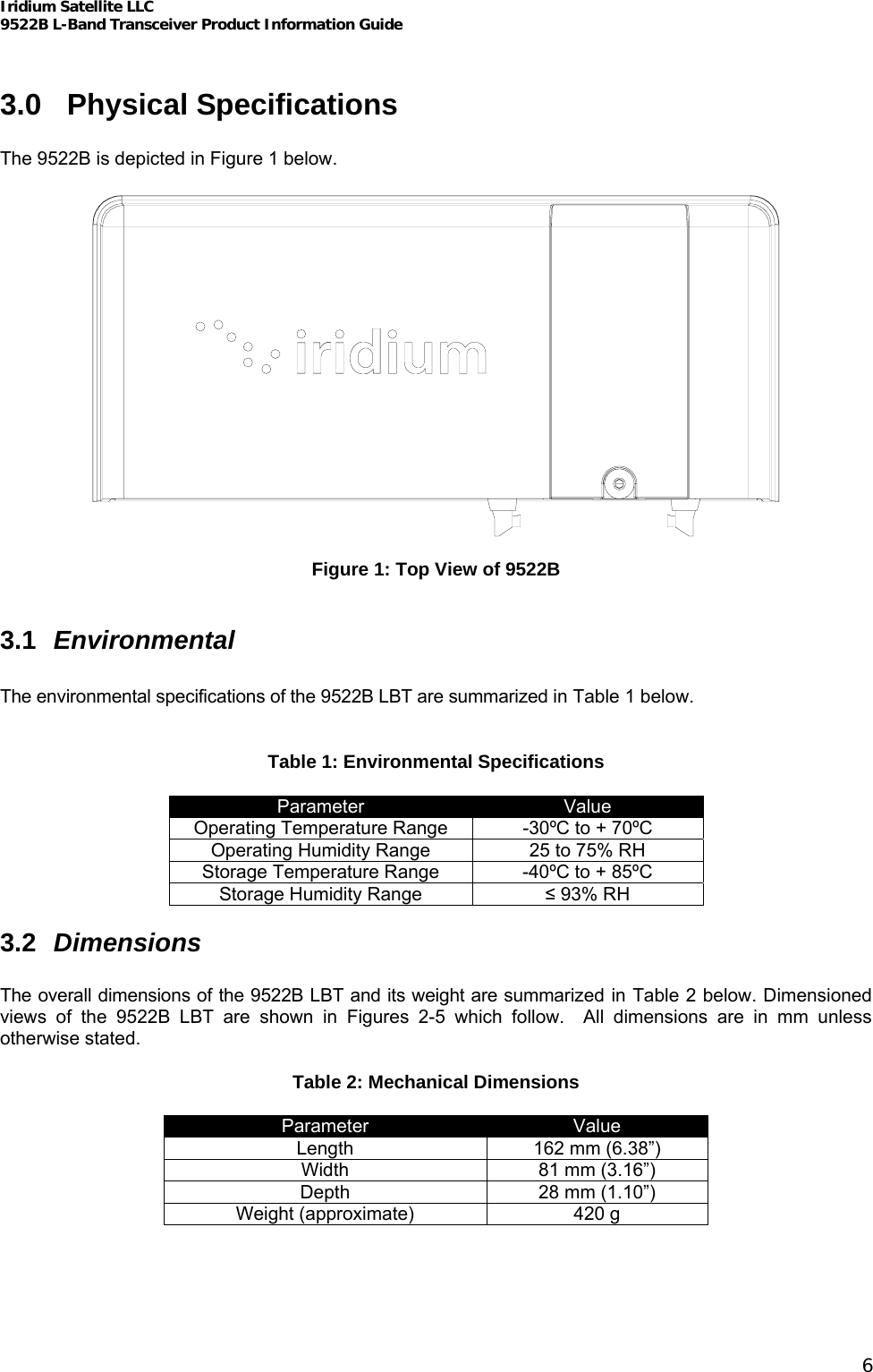
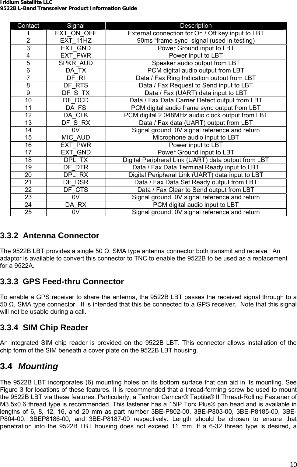
![9522B L-Band Transceiver Product Information Guide Iridium Satellite LLC 6701 Democracy Blvd., Suite 500 Bethesda, MD 20817 USA www.iridium.com Toll Free: +1.866.947.4348 [US Only] International +1.480.752.5155 email: info@iridium.com](https://usermanual.wiki/Iridium-Satellite/9522B/User-Guide-975489-Page-1.png)