Iridium Satellite 9523 9523 Voice and Data Transceiver Module User Manual 9523 Developer s Guide v2 6
Iridium Satellite LLC 9523 Voice and Data Transceiver Module 9523 Developer s Guide v2 6
UserManual.wiki
>
Iridium Satellite
>
9523 User Manual
manual
Navigation menu
Upload a User Manual
Namespaces
Wiki Guide
HTML
PDF
Info
Views
User Manual
Discussion / Help
Navigation

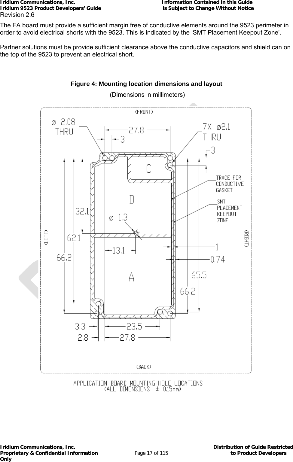
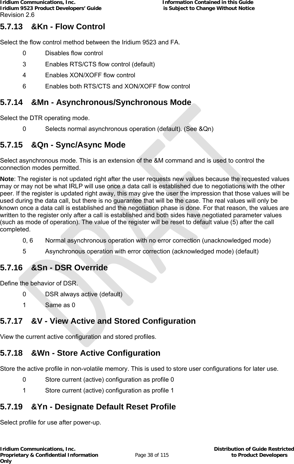
![Iridium Communications, Inc. Information Contained in this Guide Iridium 9523 Product Developers’ Guide is Subject to Change Without Notice Revision 2.6 Iridium Communications, Inc. Distribution of Guide Restricted Proprietary & Confidential Information Page 6 of 115 to Product Developers Only 5.7.51+CSCA - SMS Service Center Address ............................................................................... 545.7.52+CSCB - Select Cell Broadcast Message Types ................................................................. 555.7.53+CSCS - Select TE Character Set ....................................................................................... 555.7.54+CSMS - Select SMS Message Service .............................................................................. 555.7.55+CSTA - Select Type of Address ......................................................................................... 565.7.56+GMI - Manufacturer Identification ...................................................................................... 565.7.57+GMM - Model Identification ................................................................................................ 565.7.58+GMR - Revision .................................................................................................................. 565.7.59+GSN - Serial Number ......................................................................................................... 565.7.60+GCAP - General Capabilities ............................................................................................. 565.7.61A - Answer ............................................................................................................................ 575.7.62D - Dial ................................................................................................................................. 575.7.63Hn - Hangup ......................................................................................................................... 585.7.64S0=n - Auto-Answer ............................................................................................................. 585.7.65Xn - Extended Result Codes ................................................................................................ 585.7.66+CLVL - Volume Level Control ............................................................................................ 585.7.67+CMUT - Mute Control ......................................................................................................... 595.7.68+CRC - Cellular Result Codes ............................................................................................. 595.7.69+CVHU - Voice Hangup Control .......................................................................................... 605.7.70+CCLK - Real-Time Clock .................................................................................................... 605.7.71–MSVTS - DTMF Generation in Voice Call ......................................................................... 605.7.72–MSVTR - DTMF Received in Voice Call ............................................................................ 615.7.73–MSVLS - Local DTMF Feedback Selection ....................................................................... 615.7.74–MSSTM - Request System Time ....................................................................................... 625.7.75–MSGEO - Request Geolocation ......................................................................................... 625.7.76+CCFC - Call Forward Service ............................................................................................ 635.7.77+CLCC - Request Current Call Status ................................................................................. 645.7.78+CNUM - Read MSISDN Numbers ...................................................................................... 645.7.79+CSSSC – Supplementary Services Short Code ................................................................ 645.7.80+WIRLP - Iridium Radio Link Protocol ................................................................................. 655.7.81+WFRNG - Force IRLP Renegotiation ................................................................................. 665.7.82+WTM - IRLP Test Mode ..................................................................................................... 665.7.83+WDLDM - IRLP Dynamic Link Delay Measurement .......................................................... 675.7.84+WDAV - Register or Deregister an RS232 DAV Data Peripheral ...................................... 675.7.85+SBDWB - Short Burst Data: Write Binary Data to the Iridium 9523................................... 675.7.86+SBDRB - Short Burst Data: Read Binary Data from Iridium 9523 ..................................... 685.7.87+SBDRT - Short Burst Data: Read Text Message from the Iridium 9523 ........................... 695.7.88+SBDD - Short Burst Data: Clear SBD Message Buffer(s) ................................................. 695.7.89+SBDC - Short Burst Data: Clear SBD MOMSN ................................................................. 695.7.90+SBDS - Short Burst Data: Status ....................................................................................... 705.7.91+SBDTC - Short Burst Data: Transfer MO Buffer to MT Buffer ........................................... 705.7.92+CAR - Audio Output Control .............................................................................................. 705.7.93In – Identification .................................................................................................................. 715.7.94+CIER – Indicator Event Reporting ...................................................................................... 715.7.95+CRIS – Ring Indication Status ........................................................................................... 725.7.96+CSQ[F] – Signal Quality ..................................................................................................... 735.7.97+CULK – Unlock .................................................................................................................. 735.7.98+CVMI – Voicemail Indication .............................................................................................. 745.7.99+CICCID – Read ICC ID from sim ....................................................................................... 745.7.100+CLIP – Calling Line Identification Presentation ......................................................... 755.7.101+CLIR – Calling Line Identification Restriction ............................................................ 755.7.102+IPR - Fixed DTE Rate ................................................................................................ 765.7.103+SBDWT - Short Burst Data: Write a Text Message to the Iridium 9523 .................... 765.7.104+SBDDET - Short Burst Data: Detach ......................................................................... 775.7.105+SBDI - Short Burst Data: Initiate an SBD Session .................................................... 785.7.106+SBDIX[A] - Short Burst Data: Initiate an SBD Session Extended ............................. 79](https://usermanual.wiki/Iridium-Satellite/9523/User-Guide-1567636-Page-6.png)
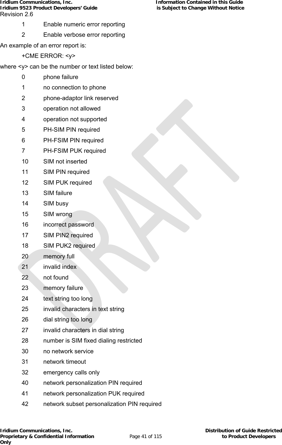
![Iridium Communications, Inc. Information Contained in this Guide Iridium 9523 Product Developers’ Guide is Subject to Change Without Notice Revision 2.6 Iridium Communications, Inc. Distribution of Guide Restricted Proprietary & Confidential Information Page 11 of 115 to Product Developers Only Le présent appareil est conforme aux CNR d'Industrie Canada applicables aux appareils radio exempts de licence. L'exploitation est autorisée aux deux conditions suivantes : (1) l'appareil ne doit pas produire de brouillage, et (2) l'utilisateur de l'appareil doit accepter tout brouillage radioélectrique subi, même si le brouillage est susceptible d'en compromettre le fonctionnement. 1.5 Software Revision Product Developers should read this document in conjunction with the “Software Release Notes” relevant to the revision of the software that is loaded into their Iridium 9523. The software release notes are available on the Iridium for Partners section of the Iridium.com website. There may be multiple software releases over the lifespan of the Iridium 9523. A software upgrade utility is provided with each software release. The utility runs on a Windows-compatible OS and will automatically upgrade the modem with the latest version. Production procedures for finished goods should ensure that the appropriate software release is loaded on each Iridium 9523 module used. The software release loaded on a particular Iridium 9523 module can be read out using the AT command interface. 1.6 Reference [1] ITU-T Recommendation V.25ter, 08/95 [2] ETS 300 642: Digital Cellular Telecommunications System (Phase 2); AT Command Set for GSM Mobile Equipment (GSM 07.07) [3] ETS 300 585: Digital Cellular Telecommunications System (Phase 2); Use of DTE-DCE Interface SMS and CBS (GSM 07.05) [4] ETS 300 520: Digital Cellular Telecommunications System (Phase 2) (GSM); Call Barring (CB) Supplementary Services – Stage 1 (GSM 02.88) [5] ETS 300 511: Digital Cellular Telecommunications System (Phase 2) (GSM); Man–Machine Interface (MMI) of the Mobile Station (MS) (GSM 02.30) [6] ETS 300 516: Digital Cellular Telecommunications System (Phase 2) (GSM); Call Waiting (CW) and Call Hold (HOLD) Supplementary Services; Stage 1 (GSM 02.83) [7] ETS 300 557: Digital Cellular Telecommunications System (Phase 2) (GSM); Mobile radio interface; Layer 3 Specification (GSM 04.08) [8] ETS 300 559: Digital Cellular Telecommunications System (Phase 2) (GSM); Point-to-Point (PP) Short Message Service (SMS) support on mobile radio interface (GSM 04.11) [9] ETS 300 536: Digital Cellular Telecommunications System (Phase 2) (GSM); Technical realization of Short Message Service (SMS) Point-to-Point (PP) (GSM 03.40) [10] ETS 300 537: Digital Cellular Telecommunications System (Phase 2) (GSM); Technical realization of Short Message Service Cell Broadcast (SMSCB) (GSM 03.41)](https://usermanual.wiki/Iridium-Satellite/9523/User-Guide-1567636-Page-11.png)
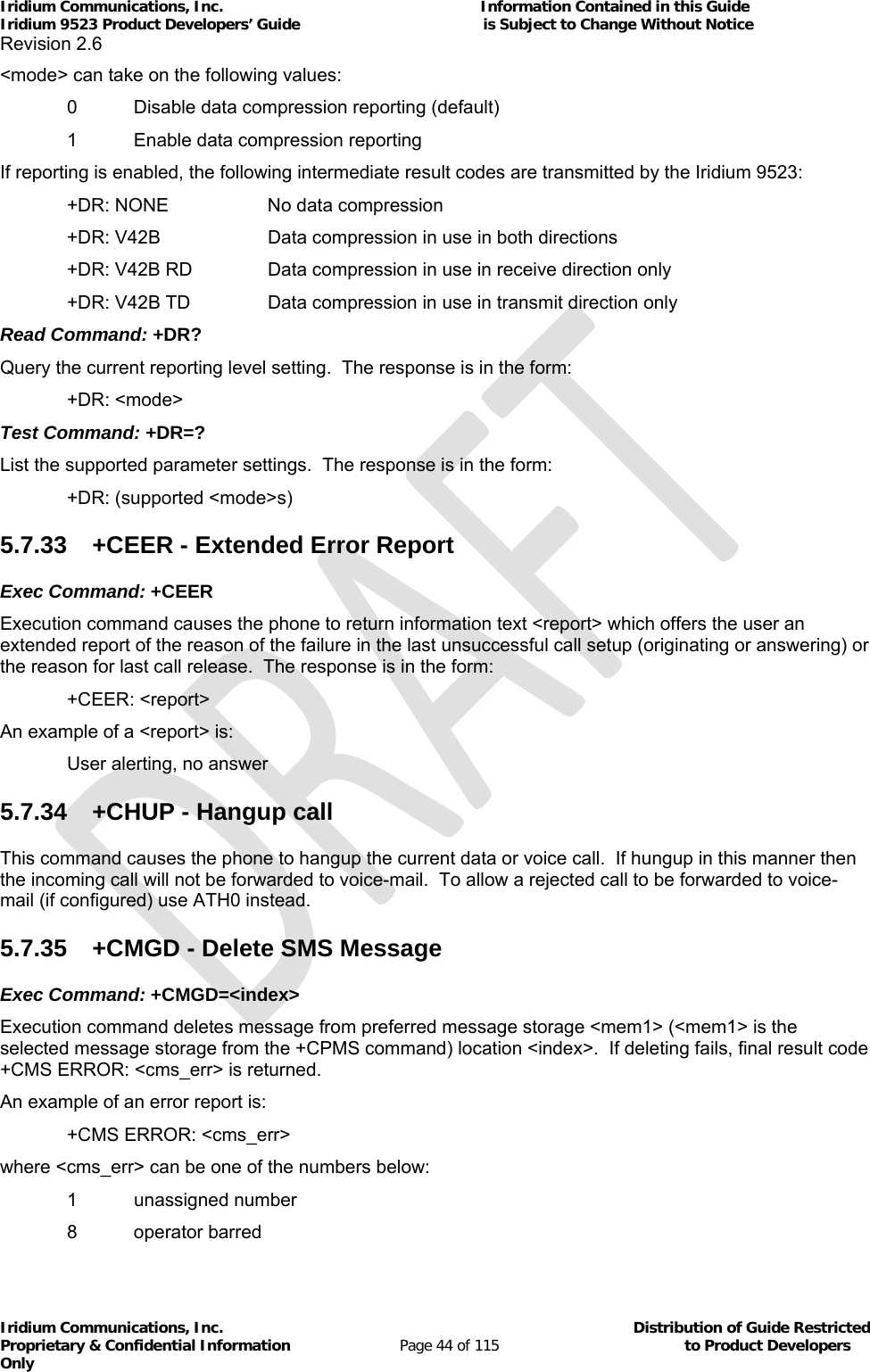
![Iridium Communications, Inc. Information Contained in this Guide Iridium 9523 Product Developers’ Guide is Subject to Change Without Notice Revision 2.6 Iridium Communications, Inc. Distribution of Guide Restricted Proprietary & Confidential Information Page 12 of 115 to Product Developers Only [11] ETS 300 515: Digital Cellular Telecommunications System (Phase 2) (GSM); Call Forwarding (CF) Supplementary Services (GSM 02.82) [12] 3GPP TS 27.007: 3rd Generation Partnership Project; Technical Specification Group Terminals; AT command set for User Equipment (UE)](https://usermanual.wiki/Iridium-Satellite/9523/User-Guide-1567636-Page-12.png)

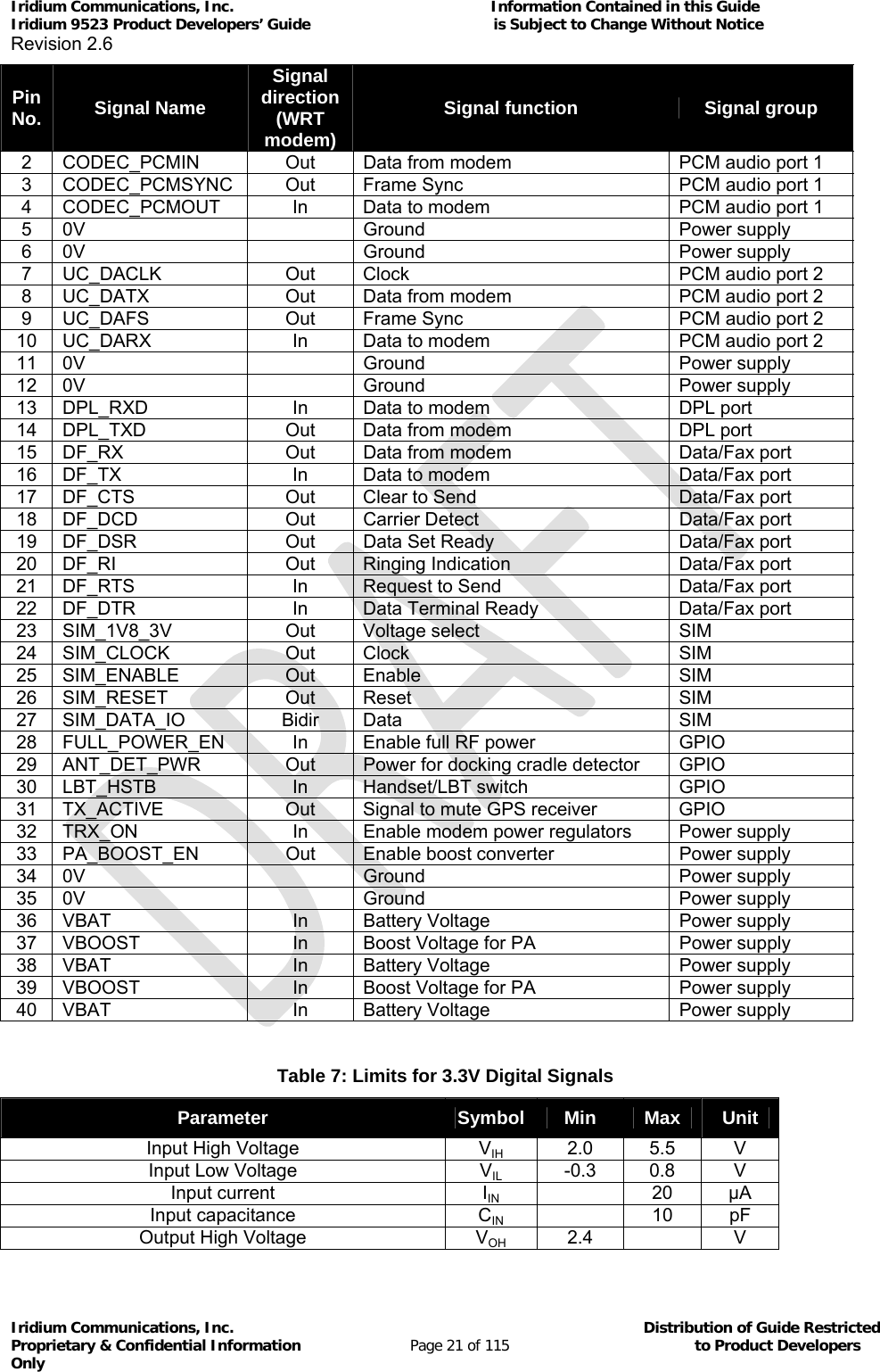

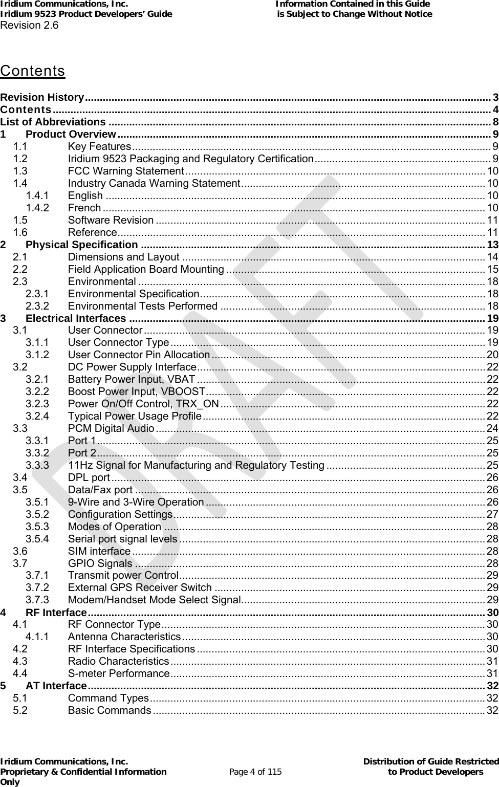
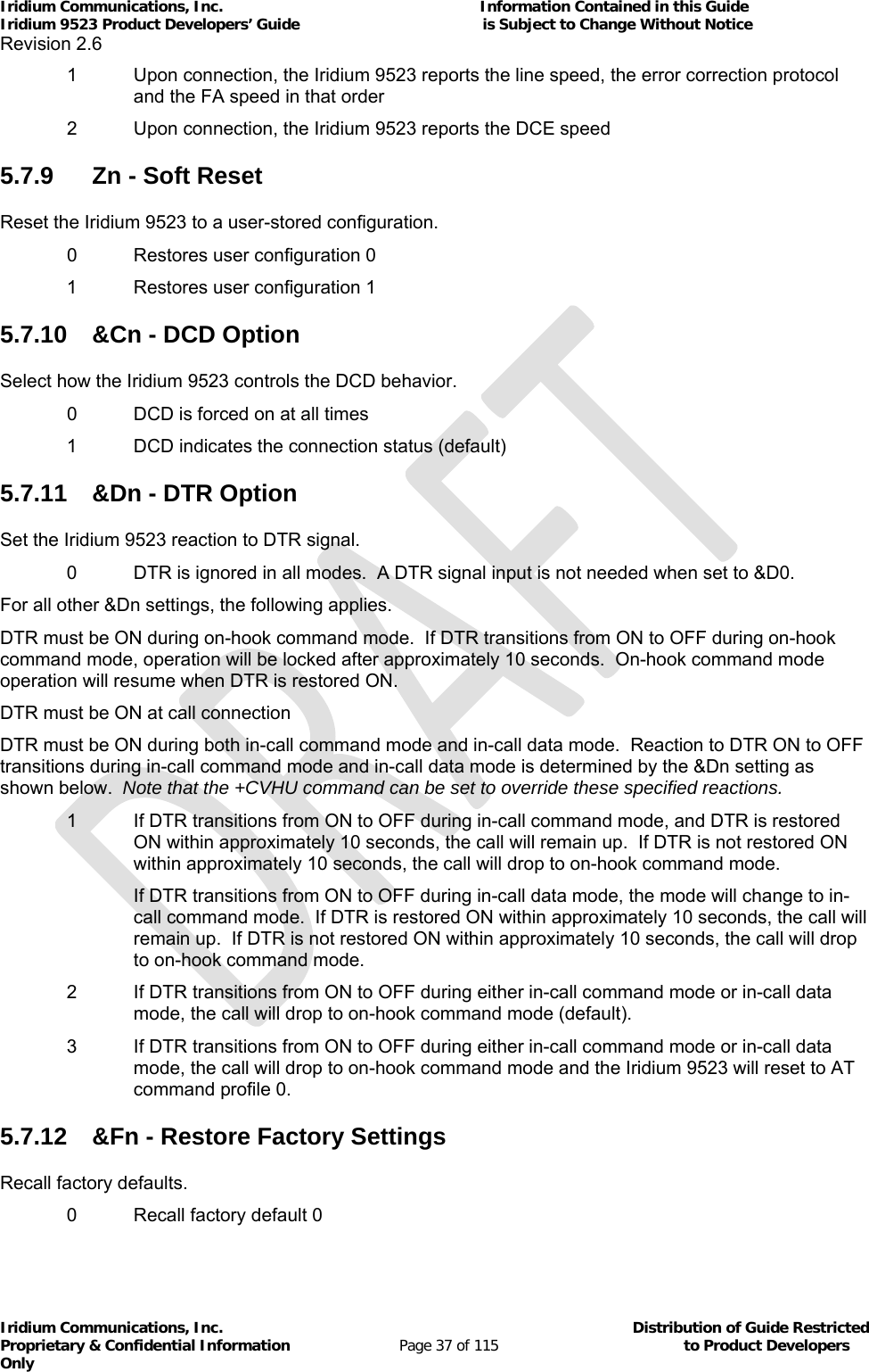
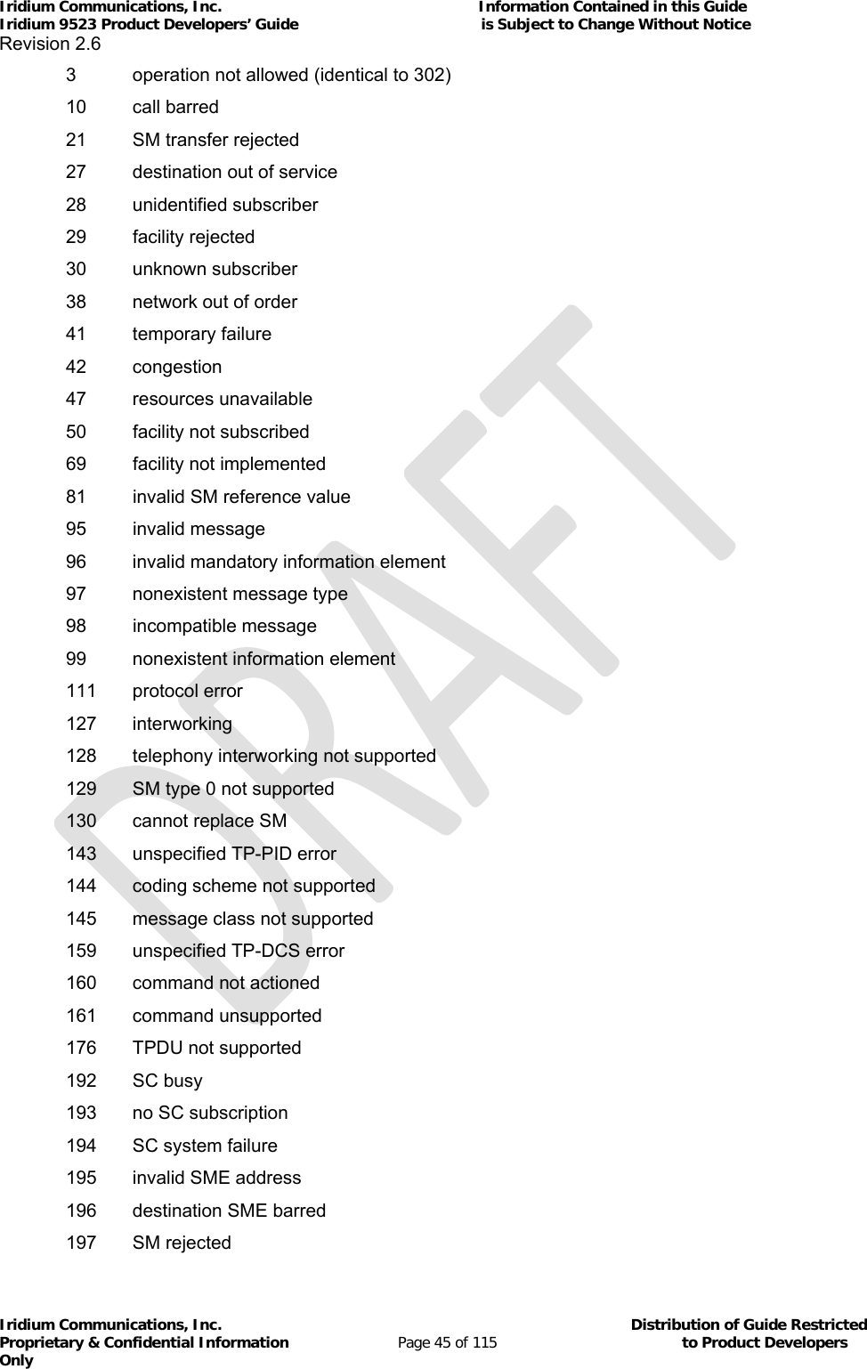
![Iridium Communications, Inc. Information Contained in this Guide Iridium 9523 Product Developers’ Guide is Subject to Change Without Notice Revision 2.6 Iridium Communications, Inc. Distribution of Guide Restricted Proprietary & Confidential Information Page 26 of 115 to Product Developers Only The frame tick signal can have any mark:space ratio but must be externally synchronized to the Iridium 9523’s internal clock. This is most easily achieved by double buffering the signal through two D-type latches clocked by CODEC_PCMCLK. 3.4 DPL port The DPL port is a three-wire asynchronous serial port. It carries 8-bit, no parity data at 115,200 baud. The DPL port enables peripherals such as handsets and SIM card readers to be interfaced to the Iridium 9523. The interface utilizes an Iridium proprietary communication bus not detailed in this document. Details can be made available after appropriate Non-Disclosure and/or License Agreements are executed. The serial data signals use standard 3.3V signals with conventional polarity. If desired, an external RS232 level converter could be fitted to the FA board to extend range. 3.5 Data/Fax port The asynchronous serial data/fax interface is comprised of eight standard RS232 data (8-bit, no parity), control, and status signals plus a ground level signal reference. This interface allows the FA to utilize the Iridium 9523’s modem functionality via AT command control. With respect to this interface, the Iridium 9523 behaves as a DCE (Data Communication Equipment), and the FA behaves as a DTE (Data Terminal Equipment). A 3-wire RS232 Data minimal interface may also be implemented; however the 9-wire interface offers better control and is the recommended implementation. Autobaud is enabled by default. Autobaud will occur on the following characters: ‘a’, ‘A’, or CR (carriage return). Autobaud will also occur on the escape sequence character, provided this is an odd number character. Normally this is set to ‘+’ in register S2. See the AT Command Reference for details. 3.5.1 9-Wire and 3-Wire Operation By default, the serial interface operates as a 9-wire connection. Table 11 describes each of the signals, where “input” means an input to the Iridium 9523, and vice-versa for “output”. Table 11: Data/Fax Port Serial Interface Signals Signal Description RX Active high data output [The FA receives the data from the Iridium 9523] TX Active high data input [Data is transmitted from the FA to the Iridium 9523] GND 0V RTS Active low flow control input CTS Active low flow control output RTS and CTS are used together to implement hardware flow control when enabled with AT&K3, refer to section 5.7.13 DTR Active low handshaking input AT&Dn controls how the Iridium 9523 uses DTR, refer to section 5.7.11 DSR Active low handshaking output The Iridium 9523 drives DSR ON The FA may use this signal as an indication that the Iridium 9523 is powered up and ready to receive AT commands](https://usermanual.wiki/Iridium-Satellite/9523/User-Guide-1567636-Page-26.png)
![Iridium Communications, Inc. Information Contained in this Guide Iridium 9523 Product Developers’ Guide is Subject to Change Without Notice Revision 2.6 Iridium Communications, Inc. Distribution of Guide Restricted Proprietary & Confidential Information Page 28 of 115 to Product Developers Only 3.5.3 Modes of Operation The serial interface is always in one of three modes: command mode, SBD data mode or SBD session mode. When the data port is in command mode, AT commands can be entered to control the Iridium 9523. In command mode, flow control has no effect, with the RTS input ignored and the CTS output driven ON (low). When in SBD data mode, the Iridium 9523 is transferring binary or text SBD message data to or from the FA. In SBD data mode: All characters from the FA not forming part of the message data are ignored (i.e. no AT commands may be entered) No unsolicited result codes are issued RTS/CTS flow control, if enabled, is active. When RTS is OFF (high), the Iridium 9523 suspends transfer of data to the FA; when CTS is OFF (high), the Iridium 9523 expects the FA to suspend transfer of data. When in SBD session mode, the Iridium 9523 is attempting to conduct an SBD session with the network. In SBD session mode: The FA must wait for the +SBDI [X][A]session result code All characters from the FA are ignored Unsolicited result codes are issued where those codes have been enabled Transitions between the modes of operation are performed automatically by the Iridium 9523 in response to the SBD AT Commands; the FA has no other control over the mode. 3.5.4 Serial port signal levels The inputs on the Iridium 9523 Data/Fax serial port (RTS, DTR and TXD) will operate correctly at 3.3V digital signal levels. The five outputs from the Iridium 9523 Data/Fax serial port (DCD, DSR, CTS, RI and RXD) are all at 3.3V digital levels. RS-232 interface chips can be fitted to the FA board if connection to an external RS232 link is required. 3.6 SIM interface The Iridium 9523 needs an external Iridium SIM card and socket to be connected to its SIM interface. The signals operate at 3.3V logic levels, so an external SIM level converter such as the ONSemi NCN4555 must be connected between the Iridium 9523 and the SIM connector/socket to allow 3V or 1.8V SIM cards to be used. An external SIM card reader may also be interfaced as a peripheral to the Iridium 9523 via the DPL interface. A SIM card in the external reader will take precedence over the SIM chip connected to the SIM interface when both are present. 3.7 GPIO Signals There are four GPIO signals to the Iridium 9523, as described in this section.](https://usermanual.wiki/Iridium-Satellite/9523/User-Guide-1567636-Page-28.png)
![Iridium Communications, Inc. Information Contained in this Guide Iridium 9523 Product Developers’ Guide is Subject to Change Without Notice Revision 2.6 Iridium Communications, Inc. Distribution of Guide Restricted Proprietary & Confidential Information Page 33 of 115 to Product Developers Only Some extended commands incorporate set, read, and test modes. For example, AT–MSVTR is entered as AT–MSVTR=n in set mode to enable/disable receipt of DTMF messages. It is entered as AT–MSVTR? in read mode to query its current setting and is entered as AT–MSVTR=? in test mode to query its range of valid settings. Extended commands are grouped as shown below. Extended Cellular Commands: +C prefix Used for GSM cellular phone-like functions Standards: ETSI specifications GSM 07.07 [2] and GSM 07.05 [3] Extended Data Compression Commands: +D prefix Used for data compression Standard: V.25ter [1] Extended Generic Commands: +G prefix Used for generic DCE issues such as identities and capabilities Standard: V.25ter [1] Extended Interface Control Commands: +I prefix Used to control the FA interface Standard: V.25ter [1] Extended Short Burst Data Commands: +S prefix Used for Short Burst Data messaging Iridium Satellite Product Proprietary Commands: –MS prefix Proprietary to the Iridium product line 5.4 Command and Response Characters The execution of a command string follows a left-to-right execution of each command followed by the reporting of a result code for the entire string. The ASCII character set (CCITT T.50 International Alphabet 5, American Standard Code for Information Interchange) is used for the issuance of commands and responses. Only the low-order 7 bits of each character are used for commands or parameters; the high-order bit is ignored. Upper case characters are equivalent to lower case characters.](https://usermanual.wiki/Iridium-Satellite/9523/User-Guide-1567636-Page-33.png)
![Iridium Communications, Inc. Information Contained in this Guide Iridium 9523 Product Developers’ Guide is Subject to Change Without Notice Revision 2.6 Iridium Communications, Inc. Distribution of Guide Restricted Proprietary & Confidential Information Page 34 of 115 to Product Developers Only 5.5 Command Entry An AT command is a string of characters sent by the FA to the Iridium 9523 while it is in command mode. A command string has a prefix, a body, and a terminator. The prefix consists of the ASCII characters AT or at. The body is a string of commands restricted to printable ASCII characters. The default terminator is the <CR> character. AT command entry syntax is critical, and the following rules apply: All commands (apart from A/ and +++) begin with a prefix of AT or at. The commands in a command string (apart from A/ and +++) are executed only after the return or enter key is pressed. Use of upper or lower case letters is allowed, but not a combination of both. The maximum number of characters in a command string is 128. If the numeric parameter n is omitted from the basic command entry, a value of zero is assumed for n. If an optional parameter is omitted from an extended command, the current value is implied. Optional parameters are enclosed by square brackets ([...]) in this document. Spaces entered into a command string for clarity between the AT prefix and the body of the command are ignored. Likewise, spaces entered for clarity within the command body between alpha characters and decimal parameters are ignored. The backspace or delete keys can typically be used to edit commands. Characters that precede the AT prefix are ignored. Ctrl-x can be used to abort a command line input. Consider the following six commands to be entered in a single command line: ATX0 (set basic command ATXn to n=0) AT&V (execute basic command AT&V) AT+GSN (execute extended command AT+GSN) AT+CMEE=? (query the valid range of responses of extended command AT+CMEE) AT+CPBR=1,12 (execute extended command AT+CPBR with parameters 1 and 12) AT–MSVTR? (query the current setting of extended command AT–MSVTR) The following are valid single command line entries of above six commands: at x 0 &v +gsn +cmee=? +cpbr=1,12 -msvtr? (all lower case) AT X 0 &V +GSN +CMEE=? +CPBR=1,12 –MSVTR? (all upper case)](https://usermanual.wiki/Iridium-Satellite/9523/User-Guide-1567636-Page-34.png)
![Iridium Communications, Inc. Information Contained in this Guide Iridium 9523 Product Developers’ Guide is Subject to Change Without Notice Revision 2.6 Iridium Communications, Inc. Distribution of Guide Restricted Proprietary & Confidential Information Page 39 of 115 to Product Developers Only 0 Select profile 0 (default) 1 Select profile 1 5.7.20 \Kn - Control Break Control the response of the Iridium 9523 to a break received from the FA or the remote modem according to the parameter specified. The response is different in three separate states: When a break is received from FA when Iridium 9523 is in data transfer mode: 0 Enter in-call command mode, no break sent to remote modem 1 Clear data buffers and send break to remote modem 2 Same as 0 3 Send break to remote modem immediately 4 Same as 0 5 Send break to remote modem in sequence with transmitted data (default) When a break is received from the remote modem during a non-error corrected connection: 0 Clear data buffers and send break to FA 1 Same as 0 2 Send break to FA immediately 3 Same as 2 4 Send break to FA in sequence with received data 5 Same as 4 (default) 5.7.21 %R - Display Registers Display all the S registers in the system. 5.7.22 *Pn - Power Phone Turn Iridium 9523 off. 0 Turn phone OFF 5.7.23 +CBST - Select Bearer Service Type Set Command: +CBST=[<speed>[,<name>[,<ce>]]] Select the bearer service type for mobile originated calls. <speed> can have the following values: 0 Autobauding 1 300 bps V.21 2 1200 bps V.22 4 2400 bps V.22bis 6 4800 bps V.32 7 9600 bps V.32 (default)](https://usermanual.wiki/Iridium-Satellite/9523/User-Guide-1567636-Page-39.png)
![Iridium Communications, Inc. Information Contained in this Guide Iridium 9523 Product Developers’ Guide is Subject to Change Without Notice Revision 2.6 Iridium Communications, Inc. Distribution of Guide Restricted Proprietary & Confidential Information Page 40 of 115 to Product Developers Only 65 300 bps V.110 66 1200 bps V.110 68 2400 bps V.110 70 4800 bps V.110 71 9600 bps V.110 <name> takes the following value: 0 data circuit asynchronous <ce> can only take the following value: 1 non-transparent Read Command: +CBST? Query the current bearer service type settings. Response is in the form: +CBST: <speed>,<name>,<ce> Test Command: +CBST=? List the supported <speed>, <name>, <ce>. Response is in the form: +CBST: (supported <speed>s),(supported <name>s),(supported <ce>s) 5.7.24 +CGMI - Manufacturer Identification Exec Command: +CGMI Query phone manufacturer. 5.7.25 +CGMM - Model Identification Exec Command: +CGMM Query phone model. 5.7.26 +CGMR - Revision Exec Command: +CGMR Query the phone revision. 5.7.27 +CGSN - Serial Number Exec Command: +CGSN Query the phone IMEI. 5.7.28 +CMEE - Report Mobile Equipment Error Set Command: +CMEE=[<x>] Set mobile equipment error reporting level. <x> takes the following values: 0 Disable error reporting (use ERROR result code) (default)](https://usermanual.wiki/Iridium-Satellite/9523/User-Guide-1567636-Page-40.png)
![Iridium Communications, Inc. Information Contained in this Guide Iridium 9523 Product Developers’ Guide is Subject to Change Without Notice Revision 2.6 Iridium Communications, Inc. Distribution of Guide Restricted Proprietary & Confidential Information Page 42 of 115 to Product Developers Only 43 network subset personalization PUK required 44 service provider personalization PIN required 45 service provider personalization PUK required 46 corporate personalization PIN required 47 corporate personalization PUK required 100 unknown Read Command: +CMEE? Query mobile equipment error reporting level. The response is in the form: +CMEE: <x> Test Command: +CMEE=? List the supported error reporting level. The response is in the form: +CMEE: (supported <x>s) 5.7.29 +CPAS - Phone Activity Status Exec Command: +CPAS Query phone activity status. The response is in the form: +CPAS: <x> where <x> can take the following values: 0 Ready (allows commands) 1 Unavailable (does not allow commands) 2 Unknown (may not respond to commands) 3 Data Call Ringing (allows commands) 4 Data Call In Progress (allows commands) 5.7.30 +CR - Service Reporting Control Set Command: +CR=[<mode>] Set the service reporting level. <mode> takes the following values: 0 Disable reporting (default) 1 Enable reporting If reporting is enabled, the intermediate result code +CR: <serv> is returned by the Iridium 9523. <serv> can have one of the following values: ASYNC asynchronous transparent SYNC synchronous transparent REL ASYNC asynchronous non-transparent REL SYNC synchronous non-transparent](https://usermanual.wiki/Iridium-Satellite/9523/User-Guide-1567636-Page-42.png)
![Iridium Communications, Inc. Information Contained in this Guide Iridium 9523 Product Developers’ Guide is Subject to Change Without Notice Revision 2.6 Iridium Communications, Inc. Distribution of Guide Restricted Proprietary & Confidential Information Page 43 of 115 to Product Developers Only Read Command: +CR? Query the current service reporting level settings. The response is in the form: +CR: <mode> Test Command: +CR=? List the supported reporting levels. The response is in the form: +CR: (supported <mode>s) 5.7.31 +DS - Set Data Compression Function Set Command: +DS=[<direction>[,<comp_neg>[,<max_dict>[,<max_string]]]] Set the V.42bis data compression function. <direction> can take on the following values: 0 No compression 1 Transmit only 2 Receive only 3 Both directions (default) <comp_neg> can take on the following values: 0 Do not disconnect if V.42bis is not negotiated by the remote DCE as specified in <direction> (default) 1 Disconnect if V.42bis is not negotiated by the remote DCE as specified in <direction> <max_dict> can take on the following values: 512 to 2048. Default is 512. <max_string> can take on the following values: 6 to 250. Default is 6. Read Command: +DS? Query the current data compression parameter settings. The response is in the form: +DS: <direction>,<comp_neg>,<max_dict>,<max_dict> Test Command: +DS=? List the supported data compression parameters. The response is in the form: +DS: (supported <direction>s),(supported <comp_neg>s,(supported <max_dict>s),(supported <max_dict>s) Data compression will not work if IRLP is in unacknowledged mode. Note: The register is not updated right after the user requests new values because the requested values may or may not be what IRLP will use once a data call is established due to negotiations with the other peer. If the register is updated right away, this may give the user the impression that those values will be used during the data call, but there is no guarantee that will be the case. The real values will only be known once a data call is established and the negotiation phase is done. For that reason, the values are written to the register only after a call is established and both sides have negotiated parameter values. The value of the register will be reset to default value (3) after the call is completed. 5.7.32 +DR - Data Compression Report Level Set Command: +DR=[<mode>] Set the data compression reporting level.](https://usermanual.wiki/Iridium-Satellite/9523/User-Guide-1567636-Page-43.png)
![Iridium Communications, Inc. Information Contained in this Guide Iridium 9523 Product Developers’ Guide is Subject to Change Without Notice Revision 2.6 Iridium Communications, Inc. Distribution of Guide Restricted Proprietary & Confidential Information Page 46 of 115 to Product Developers Only 208 SIM SMS storage full 209 no SMS storage capability in SIM 210 error in MS 211 memory capacity exceeded 255 unspecified error 300 phone failure 301 SMS service reserved 302 operation not allowed 303 operation not supported 304 invalid PDU mode parameter 305 invalid text mode parameter 310 no SIM 311 SIM PIN required 312 PH-SIM PIN required 313 SIM failure 314 SIM busy 315 SIM wrong 320 memory failure 321 invalid memory index 322 memory full 330 SM-SC address unknown 331 no network service 332 network timeout 500 unknown error 5.7.36 +CMGF - SMS Message Format Set Command: +CMGF=[<mode>] Set command tells the phone, which input and output format of messages to use. <mode> indicates the format of messages used with send, list, read and write commands and unsolicited result codes resulting from received messages. Mode can be either PDU mode (entire TP data units used) or text mode (headers and body of the messages given as separate parameters). Only PDU mode is supported at this time. Valid values for <mode> are: 0 PDU mode (default) Read Command: +CMGF? Read command returns the current <mode> set. Response is in the form: +CMGF: <mode> Test Command: +CMGF=?](https://usermanual.wiki/Iridium-Satellite/9523/User-Guide-1567636-Page-46.png)
![Iridium Communications, Inc. Information Contained in this Guide Iridium 9523 Product Developers’ Guide is Subject to Change Without Notice Revision 2.6 Iridium Communications, Inc. Distribution of Guide Restricted Proprietary & Confidential Information Page 47 of 115 to Product Developers Only Test command returns the list of supported <mode>s. Response is in the form: +CMGF: (list of supported <mode>s) 5.7.37 +CMGL - List SMS Messages Exec Command: +CMGL[=<stat>] Execution command returns messages with status value <stat> from message storage <mem1> (<mem1> is the selected message storage from the +CPMS command) to the FA. If listing fails, final result code +CMS ERROR: <cms_err> is returned. Valid values for <stat> are: PDU Text 0 "REC UNREAD" received unread message (i.e. new message) (default) 1 "REC READ" received read message 2 "STO UNSENT" stored unsent message (only applicable to SMs) 3 "STO SENT" stored sent message (only applicable to SMs) 4 "ALL" all messages (only applicable to +CMGL command) Response is in the following format for PDU mode: +CMGL:<index>,<stat>,[<alpha>],<length><CR><LF><pdu>[<CR><LF>+CMGL:<index>,<stat>,[<alpha>],<length><CR><LF><pdu> [...]] where: <alpha>: string type alphanumeric representation of TP-destination address or TP-originating address corresponding to the entry found in the phonebook (optional field); <length>: in PDU mode, this is the length of the actual TP data unit in octets (i.e. the RP layer SMSC address octets are not counted in the length) <pdu>: GSM 04.11 [8] SC address followed by GSM 03.40 [9] TPDU in hexadecimal format. Test Command: +CMGL=? Test command gives a list of all status values supported by the phone. Response is in the form: +CMGL: (list of supported <stat>s) 5.7.38 +CMGR - Read SMS Message Exec Command: +CMGR=<index> Execution command returns the SMS message with location value <index> from message storage <mem1> (<mem1> is the selected message storage from the +CPMS command). If status of the message is ’received unread’, status in the storage changes to ’received read’. If reading fails, final result code +CMS ERROR: <cms_err> is returned. Response is in the following format for PDU mode: +CMGR: <stat>,[<alpha>],<length><CR><LF><pdu> where: <stat>: 0 - MT message unread 1 - MT message read](https://usermanual.wiki/Iridium-Satellite/9523/User-Guide-1567636-Page-47.png)
![Iridium Communications, Inc. Information Contained in this Guide Iridium 9523 Product Developers’ Guide is Subject to Change Without Notice Revision 2.6 Iridium Communications, Inc. Distribution of Guide Restricted Proprietary & Confidential Information Page 48 of 115 to Product Developers Only 2 - MO message unsent 3 - MO message sent (When reading an MT message the first time, the status is reported as 0 (unread). The status is then changed to 1 (read), and that is reported on subsequent reads of that message.) <alpha>:string type alphanumeric representation of TP-destination address or TP-originating address corresponding to the entry found in the phonebook (optional field); <length>:in PDU mode, this is the length of the actual TP data unit in octets (i.e. the RP layer SMSC address octets are not counted in the length) <pdu>: GSM 04.11 [8] SC address followed by GSM 03.40 [9] TPDU in hexadecimal format. 5.7.39 +CMGS - Send SMS Message Exec Command: +CMGS=<length><CR><pdu><ctrl-Z/ESC> (PDU mode) Execution command sends message from the FA to the network (SMS-SUBMIT). In PDU mode, <length> is the length of the actual TP data unit in octets; <pdu> is the GSM 04.11 [8] SC address followed by GSM 03.40 [9] TPDU in hexadecimal format. PDU entry must be terminated by <ctrl-Z>. Sending can be cancelled by the <ESC> character. Response is in the following format for PDU mode: +CMGS: <mr> where <mr> is the message reference value of the message. If sending fails, final result code +CMS ERROR: <cms_err> is returned. 5.7.40 +CMGW - Write SMS Message To Memory Exec Command: +CMGW=<length>[,<stat>]<CR><pdu><ctrl-Z/ESC> (PDU mode) Execution command stores a message to memory storage <mem2> (<mem2> is selected by the +CPMS command). In PDU mode, <length> is the length of the actual TP data unit in octets; <pdu> is the GSM 04.11 [8] SC address followed by GSM 03.40 [9] TPDU in hexadecimal format. By default, message status will be set to ’stored unsent’, but parameter <stat> allows also other status values to be given. PDU entry must be terminated by <ctrl-Z>. Storing can be cancelled by sending the <ESC> character. Response is in the following format for PDU mode: +CMGW: <index> where <index> indicates the memory location where the message is stored. If storing fails, final result code +CMS ERROR: <cms_err> is returned. 5.7.41 +CMOD - Call Mode Set Command: +CMOD=[<mode>] Set command selects the call mode of further dialing commands (D) or for next answering command (A). Mode can be either single or alternating (the terms "alternating mode" and "alternating call" refer to all GSM bearer and teleservices that incorporate more than one basic service (voice, data, fax) within one call). For the satellite phones, only a single call is supported. <mode>: 0 single mode (default)](https://usermanual.wiki/Iridium-Satellite/9523/User-Guide-1567636-Page-48.png)
![Iridium Communications, Inc. Information Contained in this Guide Iridium 9523 Product Developers’ Guide is Subject to Change Without Notice Revision 2.6 Iridium Communications, Inc. Distribution of Guide Restricted Proprietary & Confidential Information Page 49 of 115 to Product Developers Only Read Command: +CMOD? Query the current call mode settings. The response is in the form: +CMOD: <mode> Test Command: +CMOD=? List the supported call modes. The response is in the form: +CMOD: (supported <mode>s) 5.7.42 +CNMI - New SMS Message Indications to DTE Set Command: +CNMI=[<mode>[,<mt>[,<bm>[,<ds>[, <bfr>]]]]] Set command selects the procedure, how receiving of new messages from the network is indicated to the FA when FA is active, e.g. DTR signal is ON. Valid values for <mode> are: 0 Buffer unsolicited result codes in the phone. If result code buffer is full, older indications are discarded and replaced with the new received indications. (default) 1 Discard indication and reject new received message unsolicited result codes when Iridium 9523-FA link is reserved (e.g. in in-call data mode). Otherwise forward them directly to the FA. 2 Buffer unsolicited result codes in the phone when Iridium 9523-FA link is reserved (e.g. in in-call data mode) and flush them to the FA after reservation. Otherwise forward them directly to the FA. Valid values for <mt> are: 0 No SMS-DELIVER indications are routed to the FA. (default) 1 If SMS-DELIVER is stored in the phone, indication of the memory location is routed to the FA using unsolicited result code: +CMTI: <mem>,<index> 2 SMS-DELIVERs (except class 2 messages and messages in the message waiting indica-tion group (store message)) are routed directly to the TE using unsolicited result code: +CMT: [<alpha>],<length><CR><LF><pdu> (PDU mode) 3 Class 3 SMS-DELIVERs are routed directly to TE using unsolicited result codes defined in <mt>=2. Messages of other data coding schemes result in indication as defined in <mt>=1. Valid values for <bm> are: 0 No CBM indications are routed to the FA. (default) Valid values for <ds> are: 0 No SMS-STATUS-REPORTs are routed to the FA. (default) 1 SMS-STATUS-REPORTs are routed to the FA using unsolicited result code: +CDS: <length><CR><LF><pdu> (PDU mode) Valid values for <bfr> are: 0 Buffer of unsolicited result codes defined within this command is flushed to the FA when <mode> 1...3 is entered (OK response is returned before flushing the codes). (default)](https://usermanual.wiki/Iridium-Satellite/9523/User-Guide-1567636-Page-49.png)
![Iridium Communications, Inc. Information Contained in this Guide Iridium 9523 Product Developers’ Guide is Subject to Change Without Notice Revision 2.6 Iridium Communications, Inc. Distribution of Guide Restricted Proprietary & Confidential Information Page 50 of 115 to Product Developers Only 1 Buffer of unsolicited result codes defined within this command is cleared when <mode> 1...3 is entered. Read Command: +CNMI? Read command returns the current settings for the SMS message indication. Response is in the form: +CNMI: <mode>,<mt>,<bm>,<ds>,<bfr> Test Command: +CNMI=? Test command returns the supported settings of the phone. Response is in the form: +CNMI: (list of supported <mode>s),(list of supported <mt>s),(list of supported <bm>s),(list of supported <ds>s),(list of supported <bfr>s) 5.7.43 +COPS - Operator Select Set Command: +COPS=[<mode>[,<format>[,<oper>]]] Set command forces an attempt to manually register the phone to the network. Only IRIDIUM as <oper> is supported. Valid values for the parameters are outlined below. <mode>: 0 automatic (<oper> field is ignored) (default) 1 manual (<oper> field is optional) <format>: 0 long format alphanumeric <oper> 1 short format alphanumeric <oper> 2 numeric <oper> <oper> is of string type enclosed by quotes“”; for example “IRIDIUM”. <format> indicates if the format is alphanumeric or numeric; long alphanumeric format can be up to 16 characters long and short format up to 8 characters; numeric format is the Location Area Identification number which consists of a three BCD (Binary Coded Decimal) digit country code plus a two BCD digit network code; hence the number has structure: (country code digit 3)(country code digit 2)(country code digit 1)(network code digit 2)(network code digit 1). Since IRIDIUM is the only operator, the short and long format is “IRIDIUM” and the numeric format is “90103”. These are the only values accepted. Note that setting the <mode> to manual does not disable automatic registration of the phone to the network. It just forces a manual registration procedure when entered. Read Command: +COPS? Read command returns the current mode, and will always respond with “000” for <mode>. This is due to the continually enabled nature of the automatic registration mode. The response is in the form: +COPS: <mode> For example: +COPS:000 Test Command: +COPS=? Test command returns the list of operators present in the network. Response is in the form:](https://usermanual.wiki/Iridium-Satellite/9523/User-Guide-1567636-Page-50.png)
![Iridium Communications, Inc. Information Contained in this Guide Iridium 9523 Product Developers’ Guide is Subject to Change Without Notice Revision 2.6 Iridium Communications, Inc. Distribution of Guide Restricted Proprietary & Confidential Information Page 51 of 115 to Product Developers Only +COPS: [list of supported (<stat>,long alphanumeric <oper>,short alphanumeric <oper>,numeric <oper>)s] [,,(list of supported <mode>s),(list of supported <format>s)] where <stat> indicates: 2 current For example: +COPS:(002),"IRIDIUM","IRIDIUM","90103",,(000-001),(000-002) 5.7.44 +CPBF - Find Phonebook Entries Exec Command: +CPBF=<findtext> Execution command returns phonebook entries (from the current phonebook memory storage selected with +CPBS) which alphanumeric fields start with string <findtext>. <findtext> should be of string type enclosed by ““; for example, “John”. Entry fields returned are location number <index n>, phone number stored there <number> (of address type <type>), and text <text> associated with the number. Response is in the following format: +CPBF: <index1>,<number>,<type>,<text>[[...]<CR><LF>+CBPF: <index2>,<number>,<type>,<text>] Test Command: +CPBF=? Test command returns the maximum lengths of <number> and <text> fields for phonebook entries. Response is in the form: +CPBF: <nlength>,<tlength> where <nlength> indicates the maximum length of <number> and <tlength> shows the maximum length of <text>. 5.7.45 +CPBR - Read Phonebook Entries Exec Command: +CPBR=<index1>[,<index2>] Execution command returns phonebook entries in location number range <index1>... <index2> from the current phonebook memory storage selected with +CPBS. If <index2> is left out, only location <index1> is returned. Entry fields returned are location number <index n>, phone number stored there <number> (of address type <type>) and text <text> associated with the number. Response is in the form: +CPBR: <index1>,<number>,<type>,<text>[[...] <CR><LF>+CPBR: <index2>,<number>,<type>,<text>] Test Command: +CPBR=? Test command returns location range supported by the current storage and the maximum lengths of <number> and <text> fields. Response is in the form: +CPBR: (list of supported <index>s),<nlength>,<tlength> where <nlength> indicates the maximum length of <number> and <tlength> shows the maximum length of <text>. 5.7.46 +CPBS - Select Phonebook Storage Set Command: +CPBS=<storage>](https://usermanual.wiki/Iridium-Satellite/9523/User-Guide-1567636-Page-51.png)
![Iridium Communications, Inc. Information Contained in this Guide Iridium 9523 Product Developers’ Guide is Subject to Change Without Notice Revision 2.6 Iridium Communications, Inc. Distribution of Guide Restricted Proprietary & Confidential Information Page 52 of 115 to Product Developers Only Set command selects phonebook memory storage <storage>, which is used by other phonebook commands. <storage> should be of string type enclosed by “”; for example, “FD”. <storage> takes the following values: FD SIM fixed dialing phonebook LD Last ten calls dialed phonebook ME Iridium 9523 phonebook MT combined Iridium 9523 and SIM phonebook (default) SM SIM phonebook Read Command: +CPBS? Read command returns currently selected memory, the number of used locations and total number of locations in the memory. Response is in the form: +CPBS: <storage>,<used>,<total> where <used> indicates the number of used locations and <total> shows the total capacity of <storage>. Test Command: +CPBS=? Test command returns supported storages. 5.7.47 +CPBW - Write Phonebook Entry Exec Command: +CPBW=[<index>][,<number>[,<type>[<text>]]] Execution command writes phonebook entry in location number <index> in the current phonebook memory storage selected with +CPBS. Entry fields written are phone number <number> (of address type <type>) and text <text> associated with the number. If those fields are omitted, phonebook entry is deleted. If <index> is left out, but <number> is given, entry is written to the first free location in the phonebook. Both <text> and <number> should be of string type enclosed by ““; for example, “John”,”1234”. Test Command: +CPBW=? Test command returns the location range supported by the current storage, the maximum length of <num-ber> field, supported number formats of the storage, and the maximum length of <text> field. Response is in form: +CPBW: (list of supported <index>s),<nlength>,(list of supported <type>s),<tlength> 5.7.48 +CPIN - Enter PIN Set Command: +CPIN=<pin>[,<newpin>] Set command sends to the phone a password which is necessary before it can be operated (SIM Card PIN Code, SIM PUK, etc.). If no password request is pending, no action is taken by the phone. If the password required is SIM PUK, then <newpin> is required, where <newpin> is the new SIM Card PIN to replace the old SIM Card PIN. If the password required is SIM PUK2, then <newpin> is required, where <newpin> is the new SIM Card PIN2 to replace the old SIM Card PIN2 Both <pin> and <newpin> should be of string type enclosed by “ “; for example, ”1234”. Read Command: +CPIN?](https://usermanual.wiki/Iridium-Satellite/9523/User-Guide-1567636-Page-52.png)
![Iridium Communications, Inc. Information Contained in this Guide Iridium 9523 Product Developers’ Guide is Subject to Change Without Notice Revision 2.6 Iridium Communications, Inc. Distribution of Guide Restricted Proprietary & Confidential Information Page 53 of 115 to Product Developers Only Read command returns an alphanumeric string indicating whether some password is required or not. Response is in the form: +CPIN: <code> where <code> can be one of the following: READY Iridium 9523 is not waiting for any password. PH PIN Iridium 9523 is waiting for Phone Unlock Code to be given. SIM PIN Iridium 9523 is waiting for SIM Card PIN1 Code to be given. SIM PUK Iridium 9523 is waiting for SIM PUK to be given (because SIM PIN1 is blocked). SIM PIN2 Iridium 9523 is waiting for SIM PIN2 to be given.* SIM PUK2 Iridium 9523 is waiting for SIM PUK2 to be given (because SIM PIN2 is blocked). *Note: The response “SIM PIN2” is somewhat misleading, because it indicates one of three possible scenarios: 1. PIN1 has already been successfully entered (thus equivalent to the READY response). 2. No PIN1 is required (thus equivalent to the READY response). 3. The phone is waiting for PIN2 (used to access Fixed Dialing settings and other subscription-based features). In any of these three cases, the phone should be available to place and receive calls. Note: +CPIN is closely related to +CLCK and +CPWD. See these commands for additional information. 5.7.49 +CPMS - Select Preferred SMS Message Storage Set Command: +CPMS=<mem1>[, <mem2>[,<mem3>]] Set command selects memory storages <mem1>, <mem2> and <mem3>. <mem1> is the memory from which messages are read and deleted; <mem2> is the memory to which writing and sending operations are made; <mem3> is the memory to which received SMS messages are to be stored. If a chosen storage is not appropriate for the phone, final result code +CMS ERROR: <cms_err> is returned. Valid values for <mem1>, <mem2> and <mem3> are: "SM" SIM message storage Response is in the form: +CPMS: <used1>,<total1>,<used2>,<total2>,<used3>,<total3> where <used1>: number of messages currently in <mem1> <total1>: total number of message locations in <mem1> <used2>: number of messages currently in <mem2> <total2>: total number of message locations in <mem2> <used3>: number of messages currently in <mem3> <total3>: total number of message locations in <mem3> Read Command: +CPMS? Read command returns the current storage selected, usage and capacity. Response is in the form:](https://usermanual.wiki/Iridium-Satellite/9523/User-Guide-1567636-Page-53.png)
![Iridium Communications, Inc. Information Contained in this Guide Iridium 9523 Product Developers’ Guide is Subject to Change Without Notice Revision 2.6 Iridium Communications, Inc. Distribution of Guide Restricted Proprietary & Confidential Information Page 54 of 115 to Product Developers Only +CPMS: <mem1>,<used1>,<total1>,<mem2>,<used2>,<total2>, <mem3>,<used3>,<total3> Test Command: +CPMS=? Test command returns lists of memory storages supported by the phone. Response is in the form: +CPMS: (list of supported <mem1>s),(list of supported <mem2>s), (list of supported <mem3>s) 5.7.50 +CREG - Network Registration Set Command: +CREG=[<n>] Set command controls the presentation of an unsolicited result code +CREG: <stat> when <n>=1 and there is a change in the Iridium 9523 network registration status, or code +CREG: <stat>[,<lac>,<ci>] when <n>=2 and there is a change in the registration status of the phone. Valid values for <n> are: 0 disable network registration unsolicited result code (default) 1 enable network registration unsolicited result code +CREG: <stat> 2 enable network registration and location information unsolicited result code +CREG: <stat>[,<lac>,<ci>]. <lac> indicates the location area code in string format; <ci> is in the cell identifier which is not applicable to IRIDIUM. <stat> can be one of the following: 0 not registered, Iridium 9523 is not currently searching a new operator to register to 1 registered, home network 2 not registered, but Iridium 9523 is currently searching a new operator to register to 3 registration denied 4 unknown 5 registered, roaming Read Command: +CREG? Read command returns the status of result code presentation and an integer <stat> which shows the network registration status of the phone. Location information elements <lac> and <ci> are returned only when <n>=2 and phone is registered in the network. Response is in the form: +CREG: <n>,<stat>[,<lac>,<ci>] Test Command: +CREG=? Test command lists the supported settings for +CREG. Response is in the form: +CREG: (list of supported <n>s) 5.7.51 +CSCA - SMS Service Center Address Set Command: +CSCA=<sca>[,<tosca>] Set command updates the SMSC address, through which mobile originated SMs are transmitted. In PDU mode, setting is used by the send and write commands, but only when the length of the SMSC address coded into <pdu> parameter equals zero. <sca>: GSM 04.11 [8] RP SC address Address-Value field in string format (i.e., enclosed by quotes ““); <tosca>: GSM 04.11 [8] RP SC address Type-of-Address octet in integer format; Read Command: +CSCA?](https://usermanual.wiki/Iridium-Satellite/9523/User-Guide-1567636-Page-54.png)
![Iridium Communications, Inc. Information Contained in this Guide Iridium 9523 Product Developers’ Guide is Subject to Change Without Notice Revision 2.6 Iridium Communications, Inc. Distribution of Guide Restricted Proprietary & Confidential Information Page 55 of 115 to Product Developers Only Read command returns the current service center address. Response is in the form: +CSCA: <sca>,<tosca> 5.7.52 +CSCB - Select Cell Broadcast Message Types Read Command: +CSCB? Read command returns the current values for <mode>, <mids> and <dcss>. Response is in the form: +CSCB: <mode>,<mids>,<dcss> Test Command: +CSCB=? Test command returns supported modes. Response is in the form: +CSCB: (list of supported <mode>s) 5.7.53 +CSCS - Select TE Character Set Set Command: +CSCS=[<chset>] Set command informs the phone which character set <chset> is used by the FA. Only the IRA character set is currently supported. <chset> should be of string type enclosed by ““; for example, “IRA”. Valid values for <chset> are: "IRA" international reference alphabet (ITU-T T.50) Read Command: +CSCS? Read command returns the current character set used. Response is in the form: +CSCS: <chset> Test Command: +CSCS=? Test command returns the supported character set of the phone. Response is in the form: +CSCS: (list of supported <chset>s) 5.7.54 +CSMS - Select SMS Message Service Set Command: +CSMS=<service> Set command selects short messaging service <service>. It returns the types of messages supported by the phone: <mt> for mobile terminated messages, <mo> for mobile originated messages and <bm> for broadcast type messages. If chosen service is not supported, final result code +CMS ERROR: <cms_err> shall be returned. Only message service type 0 is currently supported. Valid values for <service> are: 0 GSM 03.40 [9] and 03.41 [10] (the syntax of SMS AT commands is compatible with GSM 07.05 [3] Phase 2 version 4.7.0) (default) Response is in the form: +CSMS: <mt>,<mo>,<bm> where, <mt>, <mo>, <bm>: 0 type not supported 1 type supported Read Command: +CSMS?](https://usermanual.wiki/Iridium-Satellite/9523/User-Guide-1567636-Page-55.png)
![Iridium Communications, Inc. Information Contained in this Guide Iridium 9523 Product Developers’ Guide is Subject to Change Without Notice Revision 2.6 Iridium Communications, Inc. Distribution of Guide Restricted Proprietary & Confidential Information Page 56 of 115 to Product Developers Only Read command returns the current message service type set. Response is in the form: +CSMS: <service>,<mt>,<mo>,<bm> Test Command: +CSMS=? Test command returns the supported message services of the phone. Response is in the form: +CSMS: (list of supported <service>s) 5.7.55 +CSTA - Select Type of Address Set Command: +CSTA=[<type>] Select the type of number for the dial command D. <type> is the type of address in integer format specified in GSM 4.08 subclause 10.5.4.7. Typical values for <type> are: 129 Unknown type (default) 145 International number Read Command: +CSTA? Query the current address type settings. The response is in the form: +CSTA: <type> Test Command: +CSTA=? List the supported address type settings. The response is in the form: +CSTA: (supported <type>s) 5.7.56 +GMI - Manufacturer Identification Exec Command: +GMI Query phone manufacturer. This command is similar to +CGMI. 5.7.57 +GMM - Model Identification Exec Command: +GMM Query phone model. This command is similar to +CGMM. 5.7.58 +GMR - Revision Exec Command: +GMR Query the phone revision. This command is similar to +CGMR. 5.7.59 +GSN - Serial Number Exec Command: +GSN Query the phone IMEI. This command is similar to +CGSN. 5.7.60 +GCAP - General Capabilities Exec Command: +GCAP Query the phone’s overall capabilities.](https://usermanual.wiki/Iridium-Satellite/9523/User-Guide-1567636-Page-56.png)
![Iridium Communications, Inc. Information Contained in this Guide Iridium 9523 Product Developers’ Guide is Subject to Change Without Notice Revision 2.6 Iridium Communications, Inc. Distribution of Guide Restricted Proprietary & Confidential Information Page 57 of 115 to Product Developers Only 5.7.61 A - Answer Answer immediately. This causes the Iridium 9523 to answer the incoming data or voice call. 5.7.62 D - Dial Dial a data or voice call number. The dial command causes the Iridium 9523 to enter originate mode and act as an auto dialer for connection to other modems or voice lines. The usual format is ATDnx..x where n is a Dial Modifier and x is a number. The following are valid numbers: 0123456789*#ABC. Dial modifiers are used to alter the manner in which the Iridium 9523 dials. L Redial last number + International dialing prefix. Allows the international access code to be omitted from dial string. > Direct dial from phonebook locations. See subsection below for further details. ; Start up a voice call. This modifier should be given after the dialing digits (or modifiers). Any character received from the FA during the call establishment phase will cause the call attempted to be terminated. 5.7.62.1 D> - Direct Dial From Phonebook The Iridium 9523 and SIM contain phonebooks which have a phone number and an alphanumeric field for each phonebook entry location. The use of V.25ter dialing command ensures that direct dialing from phone memory and SIM phonebook is possible through ordinary communications software which just gives the phone number field to be filled and then uses the D command to originate the call. Available memories may be queried with Select Phonebook Storage test command +CPBS=?, and location range for example with Read Phonebook Entries test command +CPBR=?. Execute commands: D><str>[;] Originate call to phone number which corresponding alphanumeric field is <str> (if possible, all available memories should be searched for the correct entry). <str> is of string type value and should enclosed by ““ (e.g., “John”). D> mem<n>[;] Originate call to phone number in memory mem entry location <n> (available memories may be queried with Select Phonebook Storage test command +CPBS=?). mem can be one of the following: FD SIM fixed dialing phonebook LD Last ten calls dialed phonebook ME Phone memory MT combined phone and SIM phonebook locations SM SIM phonebook D><n>[;] Originate call to phone number in entry location <n> (the command Select Phonebook Memory Storage +CPBS setting determines which phonebook storage is used).](https://usermanual.wiki/Iridium-Satellite/9523/User-Guide-1567636-Page-57.png)
![Iridium Communications, Inc. Information Contained in this Guide Iridium 9523 Product Developers’ Guide is Subject to Change Without Notice Revision 2.6 Iridium Communications, Inc. Distribution of Guide Restricted Proprietary & Confidential Information Page 59 of 115 to Product Developers Only 5 Equivalent to level 5 displayed on a handset’s volume indicator 6 Equivalent to level 6 displayed on a handset’s volume indicator 7 Equivalent to level 7 displayed on a handset’s volume indicator Test Command: +CLVL=? List the supported volume level settings. The response is in the form: +CLVL: (supported <level>s) 5.7.67 +CMUT - Mute Control Exec Command: +CMUT=<n> This command is used to enable and disable the uplink voice muting during a voice call. <n> can take one of the following values: 0 mute off 1 mute on Read Command: +CMUT? Query the current mute setting. The response is in the form: +CMUT: <n> Test Command: +CMUT=? List the supported mute settings. The response is in the form: +CMUT: (supported <n>s) 5.7.68 +CRC - Cellular Result Codes Set Command: +CRC=[<mode>] Set the extended format of incoming data or voice call indication. <mode> takes the following values: 0 Disable extended format (default) 1 Enable extended format If extended format is enabled, the unsolicited result code +CRING: <type> is returned by the Iridium 9523 instead of RING, where <type> can be one of the following: ASYNC asynchronous transparent SYNC synchronous transparent REL ASYNC asynchronous non-transparent REL SYNC synchronous non-transparent FAX facsimile VOICE normal voice Read Command: +CRC? Query the current result code settings. The response is in the form: +CR: <mode> Test Command: +CRC=?](https://usermanual.wiki/Iridium-Satellite/9523/User-Guide-1567636-Page-59.png)
![Iridium Communications, Inc. Information Contained in this Guide Iridium 9523 Product Developers’ Guide is Subject to Change Without Notice Revision 2.6 Iridium Communications, Inc. Distribution of Guide Restricted Proprietary & Confidential Information Page 60 of 115 to Product Developers Only List the supported result code settings. The response is in the form: +CR: (supported <mode>s) 5.7.69 +CVHU - Voice Hangup Control Set Command: +CVHU=[<mode>] Selects whether the Hn (hangup) or &Dn command shall cause a voice call connection to be disconnected or not. <mode> can take one of the following values: 0 Ignore &Dn command specified reaction to DTR ON to OFF transitions. Disconnect as reaction to Hn command. OK response given. 1 Ignore &Dn command specified reaction to DTR ON to OFF transitions. Ignore Hn command. OK response given. 2 Comply with &Dn command specified reaction to DTR ON to OFF transitions. Disconnect as reaction to Hn command (default). Read Command: +CVHU? Query the current voice control hangup settings. The response is in the form: +CVHU: <mode> Test Command: +CVHU=? List the supported voice control hangup settings. The response is in the form: +CVHU: (supported <mode>s) 5.7.70 +CCLK - Real-Time Clock Set Command: +CCLK=[<time>] Sets the real-time clock of the Iridium 9523. If setting fails, ERROR is returned. <time>: string type value; format is “yy/MM/dd,hh:mm:sszz”, where characters indicate year (two last digits), month, day, hour, minutes, seconds and time zone. There is no blank space between the two double quotes. Since time zone feature is not supported in Iridium, this particular field (zz) is ignored if it is entered. The range of valid years is between 1970 and 2058. For example, May 15, 2011, 22:10:00 hours can be set using +CCLK= “11/05/15,22:10:00”. Read Command: +CCLK? Read command returns the current setting of the clock. +CCLK: <time> 5.7.71 –MSVTS - DTMF Generation in Voice Call Set Command: –MSVTS=<string> Generate the specified DTMF tone (i.e., send tone DTMF message to network). The parameter <string> shall consist of elements in a list where each element is separated by a comma. Each element should either be (1) a single ASCII character; or (2) string that follows the format: <tone>[,<time>] with each string enclosed in square brackets “[]”. The string parameter values are defined as follows: <tone> specifies the string of tones to be played or generated. The valid values are (in ASCII): ‘0’-’9’, ‘#’, ‘*’ <time> specifies the duration of each tone in 180-millisecond unit. Default value is 1 for 180 ms.](https://usermanual.wiki/Iridium-Satellite/9523/User-Guide-1567636-Page-60.png)
![Iridium Communications, Inc. Information Contained in this Guide Iridium 9523 Product Developers’ Guide is Subject to Change Without Notice Revision 2.6 Iridium Communications, Inc. Distribution of Guide Restricted Proprietary & Confidential Information Page 61 of 115 to Product Developers Only For example, the command string –MSVTS=1,[9,2],[5,3] will: 1. Generate DTMF 1 with a duration of 180 ms (default) 2. Generate DTMF 9 with a duration of 360 ms (2 * 180 ms) 3. Generate DTMF 5 with a duration of 540 ms (3 * 180 ms) Test Command: –MSVTS=? List the supported parameter settings. The response is in the form: –MSVTS: (supported <tone>s),(supported <time>s) Note: DTMF generated with the –MSVTS command is never played back locally as tones and is therefore neither played nor muted under control of the –MSVLS command. 5.7.72 –MSVTR - DTMF Received in Voice Call Set Command: –MSVTR=[<mode>] Disable or enable the receiving of DTMF messages from the network. <mode> takes one of the following values: 0 Receiving of DTMF disabled (default) 1 Receiving of DTMF enabled If receiving DTMF is enabled, the Iridium 9523 sends the following unsolicited result code every time a DTMF inband signaling data is received from the network while in a voice call: –MSTRX: <tone>,<event> where <tone> is the DTMF tone received (‘0’-’9’, ‘#’, ‘*’, ‘A’-’D’) and <event> can be one of the following: 0 tone stopped (i.e. key released) 1 tone started (i.e. key pressed) Read Command: –MSVTR? Query the current parameter settings. The response is in the form: –MSVTR: <mode> Test Command: –MSVTR=? List the supported parameter settings. The response is in the form: –MSVTR: (supported <mode>s) 5.7.73 –MSVLS - Local DTMF Feedback Selection Set Command: –MSVLS=[<mode>] Disable or enable playing of DTMF tones locally (i.e. feedback tones) while in a voice call. <mode> takes one of the following values: 0 No mute. Play all DTMF tones (default) when pressed or received while in voice call. 1 Enable mute mode. Mute both pressed or received DTMF tones while in voice call. Read Command: –MSVLS? Query the current parameter settings. The response is in the form:](https://usermanual.wiki/Iridium-Satellite/9523/User-Guide-1567636-Page-61.png)
![Iridium Communications, Inc. Information Contained in this Guide Iridium 9523 Product Developers’ Guide is Subject to Change Without Notice Revision 2.6 Iridium Communications, Inc. Distribution of Guide Restricted Proprietary & Confidential Information Page 63 of 115 to Product Developers Only <time_stamp> is assigned by the Iridium 9523 when the geolocation grid code received from the network is stored to Iridium 9523 internal memory. Current Iridium system time, which is a running count of 90 millisecond intervals, is used for the time stamp. Time stamp is a 32-bit integer displayed in hexadecimal form. 5.7.76 +CCFC - Call Forward Service Exec Command: +CCFC=<reason>,<mode>[,<number>[,<type>[,class>[,<subaddr>[,<satype>[,<time>]]]]]] This command is based on GSM 07.07 [2] subclause 7.10, and allows control of the call forwarding supplementary service according to GSM 02.82 [11]. Registration, erasure and status query are supported. The valid values for the parameters are as follows: <reason> takes one of the following values: 0 unconditional 1 mobile busy 2 no reply 3 not reachable 4 all call forwarding (refer GSM 02.30 [5]) 5 all conditional call forwarding (refer GSM 02.30 [5]) <mode> takes one of the following values: 0 disable (not used in Call Forward) 1 enable (not used in Call Forward) 2 query status 3 registration 4 erasure <number>: quoted string type phone number of forwarding address. It contains digits only, or empty string if not applicable. <type>: type of address octet in integer format (refer to GSM 04.08 [7] subclause 10.5.4.7); default 145 when dialing string is international number, otherwise 129 <classx>: is a sum of integers each representing a class of information: 1 voice (telephony) 2 data <subaddr>: string type sub-address, not supported by Iridium <satype>: type of sub-address, not supported by Iridium <time>: string containing number of seconds (up to 30, in multiples of 5). When ‘no reply’ is enabled or queried, this gives the time in seconds to wait before call is forwarded. if <mode>=2 and command is successful, the Iridium 9523 returns a response in the form: +CCFC:<status>,<class>[,<number>,<type>] Where <status> may be as follows: 0 not active](https://usermanual.wiki/Iridium-Satellite/9523/User-Guide-1567636-Page-63.png)
![Iridium Communications, Inc. Information Contained in this Guide Iridium 9523 Product Developers’ Guide is Subject to Change Without Notice Revision 2.6 Iridium Communications, Inc. Distribution of Guide Restricted Proprietary & Confidential Information Page 64 of 115 to Product Developers Only 1 active For example: +CCFC:0,1 +CCFC:1,1,”+441223420024”,145 +CCFC:2,3,”00881662990000”,,1,,,”30” Test Command: +CCFC=? List supported <reason>s. The response is in the form of a range rather than a list: +CCFC:(000-005) 5.7.77 +CLCC - Request Current Call Status Exec Command: +CLCC Returns the current call status of the Iridium 9523. The response is a comma separated list of call states. The number of call states in the response depends on the number of active call instances e.g. incoming calls and held calls. +CLCC: <stat>[,<stat>[,<stat>]] where <stat> (State of the Iridium 9523): 000 Active 001 Call Held 002 Dialing (MO Call) 004 Incoming (MT Call) 006 Idle Note: the form of this announcement currently differs from the standard given in 3GPP TS 27.007 [12] subclause 7.18. A change to the interface may be made to become more standard. 5.7.78 +CNUM - Read MSISDN Numbers Exec Command: +CNUM Get the MSISDN numbers of the SIM. If returning fails, ERROR is returned. Response is in the form: +CNUM:<text>,<number>,<type> <text>: alpha tag of the phone numbers <number>: MSISDN numbers <type>: if the number starts with a ‘+’, then the type is 145; otherwise the type is 129 Note: MSISDN numbers are only available if they were intentionally stored on the SIM. 5.7.79 +CSSSC – Supplementary Services Short Code Exec Command: +CSSSC=”<shortcode>” Execute the given shortcode. If the shortcode fails, a CME ERROR code is returned. Otherwise, OK is returned. Note: Shortcode functionality is only available if provisioned.](https://usermanual.wiki/Iridium-Satellite/9523/User-Guide-1567636-Page-64.png)
![Iridium Communications, Inc. Information Contained in this Guide Iridium 9523 Product Developers’ Guide is Subject to Change Without Notice Revision 2.6 Iridium Communications, Inc. Distribution of Guide Restricted Proprietary & Confidential Information Page 65 of 115 to Product Developers Only Note: This command does not support command concatenation. 5.7.80 +WIRLP - Iridium Radio Link Protocol Set Command: +WIRLP=[<ver>[,<k1>[,<k2>[,< t1>[,<n2>[,<t2>[,<r1>[,<r2>[,<t4>[,<mode>]]]]]]]]]] Set desired IRLP parameters to be negotiated with the peer at the start of the next data call. Note that these desired parameters are reset to hardcoded defaults at the end of a data call, so this command should be issued while a call is not in progress. <ver> specifies the desired IRLP version and can take the following values: 0 Default IRLP version (N0) <k1> represents the maximum number of sequentially numbered I frames that may be outstanding at any given time at downlink direction (IWF->Iridium 9523) and can take the following values: 1-105. Default is 105. <k2> represents the maximum number of sequentially numbered I frames that may be outstanding at any given time at uplink direction (Iridium 9523->IWF) and can take the following values: 1-105. Default is 105. <t1> is used to supervise the acknowledgment of transmitted unnumbered frames. The values are defined to be the earliest instant to enter the recovery procedure and can take on the following values: 27-255 (in 50-ms unit). Default is 30. <n2> is used to represent the maximum number of re-transmission attempts of a frame (e.g. I,S,N,U frame) and can take on the following values: 1-255. Default is 15. <t2 > is used to indicate the amount of time available within which the acknowledging frame must be transmitted and can take on the following values: 1-255 (in 10-ms unit). Default is 10. <r1> is used to represent the maximum number of S frames that are used to acknowledge I frames at downlink direction (IWF->Iridium 9523) and can take on the following values: 1-10. Default is 10. <r2 > is used to represent the maximum number of S frames that are used to acknowledge I frames at uplink direction (Iridium 9523->IWF) and can take on the following values: 1-10. Default is 10. <t4 > is used to supervise the re-sequencing of misordered frames. The values are defined to be the earliest instant to consider a tardy frame as lost. It can take on the following values: 20-255 (in 10-ms unit). Default is 25. <mode> is used to indicate the mode of operation and can take on the following values: 0 unacknowledged mode of operation 1 acknowledged mode of operation (default) NOTE: For the proper operation of the IRLP procedures, t2 should be less than t1 and 2*t4 should be less than t1.](https://usermanual.wiki/Iridium-Satellite/9523/User-Guide-1567636-Page-65.png)
![Iridium Communications, Inc. Information Contained in this Guide Iridium 9523 Product Developers’ Guide is Subject to Change Without Notice Revision 2.6 Iridium Communications, Inc. Distribution of Guide Restricted Proprietary & Confidential Information Page 67 of 115 to Product Developers Only 5.7.83 +WDLDM - IRLP Dynamic Link Delay Measurement Set Command: +WDLDM=[<dldm>[,<mi>[,<dtl>]]] Set the DCE dynamic link delay measurement parameters. <dldm> can take the following values: 0 measurement off (default) 1 measurement on <mi> denotes the measurement interval and can take the following values: 1-255 (in 1000-ms unit). Default is 15 for 15000 ms. <dtl> denotes the delay tolerance in the link delay difference and can take the following values: 1-100 (in 1% unit). Default is 10%. Read Command: +WDLDM? Query the current parameter settings. The response is in the form: +WDLDM: <dldm>,<mi>,<dtl> Test Command: +WDLDM=? List the supported parameter settings. The response is in the form: +WDLDM: (supported <dldm>s), (supported <mi>s), (supported <dtl>s) 5.7.84 +WDAV - Register or Deregister an RS232 DAV Data Peripheral Set Command: +WDAV=[<DP type>[,<encrypt>]] Register or deregister an RS232 DAV Data Peripheral (DP). <DP type> can take on the following values: 0 Deregister peripheral 1 Register Type 1 RS232 DAV Data Peripheral <encrypt> can take on the following values: 0 Encryption is not supported at this time Read Command: +WDAV? Query the current DP registration parameter settings. The response is in the form: +WDAV:<DP type>,<encrypt> Test Command: +WDAV=? List the supported DP registration parameters. The response is in the form: +WDAV:(supported <type>s),(supported <encrypt>s) 5.7.85 +SBDWB - Short Burst Data: Write Binary Data to the Iridium 9523 Exec Command: +SBDWB=[<SBD message length>] This command is used to transfer a binary SBD message from the FA to the single mobile originated buffer in the Iridium 9523. The mobile originated buffer can contain only one message at any one time.](https://usermanual.wiki/Iridium-Satellite/9523/User-Guide-1567636-Page-67.png)
![Iridium Communications, Inc. Information Contained in this Guide Iridium 9523 Product Developers’ Guide is Subject to Change Without Notice Revision 2.6 Iridium Communications, Inc. Distribution of Guide Restricted Proprietary & Confidential Information Page 69 of 115 to Product Developers Only There are no response codes generated by the Iridium 9523 for this command. 5.7.87 +SBDRT - Short Burst Data: Read Text Message from the Iridium 9523 Exec Command: +SBDRT This command is used to transfer a text SBD message from the single mobile terminated buffer in the Iridium 9523 to the FA. This command is similar to +SBDRB but does not provide a length indicator or checksum. The intent of this command is to provide a human friendly interface to SBD for demonstrations and application development. It is expected that most usage of SBD will be with binary messages. Once the command is entered, the SBD message in the mobile terminated buffer is sent out of the port. This command is similar to +SBDRB except no length or checksum will be provided. The maximum mobile terminated SBD message length is 1890 bytes. The mobile terminated message buffer will be empty upon power-up. Command Response: +SBDRT: <CR> {mobile terminated buffer} 5.7.88 +SBDD - Short Burst Data: Clear SBD Message Buffer(s) Exec Command: +SBDD[<Delete type>] This command is used to clear the mobile originated buffer, mobile terminated buffer or both. The <Delete type> parameter identifies which buffers are cleared. 0: Clear the mobile originated buffer 1: Clear the mobile terminated buffer 2: Clear both the mobile originated and mobile terminated buffers Using this command or power cycling the phone are the only means by which both buffers are cleared. The mobile terminated buffer will be cleared when an SBD session is initiated. Sending a message from the Iridium 9523 to the ESS does not clear the mobile originated buffer. Reading a message from the Iridium 9523 does not clear the mobile terminated buffer. Command Response: 0: Buffer(s) cleared successfully 1: An error occurred while clearing the buffer(s) 5.7.89 +SBDC - Short Burst Data: Clear SBD MOMSN Exec Command: +SBDC This command will clear (set to 0) the mobile originated message sequence number (MOMSN) stored in the Iridium 9523. The MOMSN is maintained even after power cycle.](https://usermanual.wiki/Iridium-Satellite/9523/User-Guide-1567636-Page-69.png)
![Iridium Communications, Inc. Information Contained in this Guide Iridium 9523 Product Developers’ Guide is Subject to Change Without Notice Revision 2.6 Iridium Communications, Inc. Distribution of Guide Restricted Proprietary & Confidential Information Page 71 of 115 to Product Developers Only Valid values for <n> are as follows: 0 mute 1 analog (Codec port) 2 digital (User Connector port) Read Command: +CAR? This command queries the current audio setting. Response is in the form: +CAR: <n> Test Command: +CAR=? This command lists the supported values of <n>. Response is in the form: +CAR: (list of supported values of <n>) 5.7.93 In – Identification Requests the Iridium 9523 to display information about itself. 0 “2400” (traffic channel rate for IRIDIUM data/fax) 1 “0000” (ROM checksum which is not supported so zero is output) 2 “OK” (result of ROM checksum verification which is not supported so OK is always output) 3 “XXXXXXXX” (Software revision level) 4 “IRIDIUM” (Product description) 5 “XXXX” (Country code) 6 “XXX” (Factory identity) 7 “XXXXXXXX” (Hardware specification) 5.7.94 +CIER – Indicator Event Reporting Set Command: +CIER=[<mode>[,<sigind>[,<svcind>]]] The set command enables or disables sending of the +CIEV unsolicited result code by the Iridium 9523 in case of indicator state changes. <mode> controls the processing of the +CIEV unsolicited result codes. <mode>: 0 Disable indicator event reporting; do not send +CIEV unsolicited result codes to the FA; buffer the most recent indicator event for each indicator in the Iridium 9523. (default) 1 Enable indicator event reporting; buffer the most recent +CIEV unsolicited result code for each indicator when the data port is not in command mode, and flush them to the FA on return to command mode; otherwise forward events directly to the FA. <sigind>: Control reporting of “signal quality” indicator changes. 0 No “signal quality” indicator reporting 1 Enable “signal quality” indicator reporting using result code +CIEV:0,<rssi> where <rssi> is:](https://usermanual.wiki/Iridium-Satellite/9523/User-Guide-1567636-Page-71.png)
![Iridium Communications, Inc. Information Contained in this Guide Iridium 9523 Product Developers’ Guide is Subject to Change Without Notice Revision 2.6 Iridium Communications, Inc. Distribution of Guide Restricted Proprietary & Confidential Information Page 73 of 115 to Product Developers Only 3 Incoming fax call and <sri> indicates the SBD ring indication status: 0 No SBD ring alert received 1 SBD ring alert received Note: It is valid for the Iridium 9523 to receive a telephony ring alert and an SBD ring alert at the same time. Assertion of the RI signal indicates only the presence of an alert; this command may be used to determine the type(s) of ring alert. 5.7.96 +CSQ[F] – Signal Quality Exec Command: +CSQ[F] Execution command returns the received signal strength indication <rssi> from the Iridium 9523. Response is in the form: +CSQ: <rssi> where <rssi> is: 0 Equivalent to 0 bars displayed on the signal strength indicator 1 Equivalent to 1 bar displayed on the signal strength indicator 2 Equivalent to 2 bars displayed on the signal strength indicator 3 Equivalent to 3 bars displayed on the signal strength indicator 4 Equivalent to 4 bars displayed on the signal strength indicator 5 Equivalent to 5 bars displayed on the signal strength indicator Note: The +CSQ form of the command waits for an updated signal strength reading to become available. This will usually be within two seconds of issuing the command. If the Iridium 9523 is in the process of acquiring the system, or in a satellite handoff, a delay in response of up to 10 seconds may be experienced. If the Iridium 9523 has no SIM, is awaiting a SIM PIN entry, has an invalid SIM, or has otherwise not proceeded to successful registration, the delay in response may exceed the 50 second timeout limit. Under such condition, an ERROR response will be received. To avoid a delayed response due to registration problems, issue the +CREG command to verify registration prior to entering the +CSQ command to obtain signal strength. Note: The +CSQF form of the command returns immediately, reporting the last known signal strength. Test Command: +CSQ=? List the supported signal strength indications. The response is in the form: +CSQ: (supported <rssi>s) 5.7.97 +CULK – Unlock Exec Command: +CULK=<unlock key> Unlock the SBD functionality of the ISU after it has been locked by the Gateway. The unlock key must be obtained by contacting Iridium’s customer support. <unlock key>: 0000000000000000 .. FFFFFFFFFFFFFFFF A string of 16 hexadecimal digits](https://usermanual.wiki/Iridium-Satellite/9523/User-Guide-1567636-Page-73.png)
![Iridium Communications, Inc. Information Contained in this Guide Iridium 9523 Product Developers’ Guide is Subject to Change Without Notice Revision 2.6 Iridium Communications, Inc. Distribution of Guide Restricted Proprietary & Confidential Information Page 76 of 115 to Product Developers Only 2 CLIR suppression – i.e. show the CLI for the next mobile originated call. This requires CLIR to be provisioned in one of the temporary modes. Note: If the CLIR service is not provisioned, and either invocation or suppression is requested for the next call, the next call may be rejected by the network. It is the FA’s responsibility to check whether CLIR is provisioned using the +CLIR? read command. Read Command: +CLIR? Query the current CLI Restriction provisioning status and the CLIR invocation/suppression status for the next call. The response is of the form: +CLIR:<n>,<m> <m>: 0 CLIR not provisioned 1 CLIR provisioned in permanent mode 2 Unknown (e.g. no network, etc.) 3 CLIR provisioned in temporary mode, defaulting to presentation restricted 4 CLIR provisioned in temporary mode, defaulting to presentation allowed 5.7.102 +IPR - Fixed DTE Rate Set Command: +IPR=<rate>[,<autoflag>] Set the data rate at which the Iridium 9523 will accept commands. The change in data rate takes effect after the result code (e.g. OK) is received by the FA. <rate> takes the following values: 1 600 bps 2 1200 bps 3 2400 bps 4 4800 bps 5 9600 bps 6 19200 bps (default) 7 38400 bps <autoflag> takes the following values: 0 Fixed rate – automatic rate adjustment is disabled 1 Automatic rate adjustment is enabled (default) Read Command: +IPR? Query the current data rate and automatic rate adjustment setting. The response is in the form: +IPR: <rate>,<autoflag> Test Command: +IPR=? List the supported data rates. The response is in the form: +IPR: (supported <rate>s),(supported <autoflag>s) 5.7.103 +SBDWT - Short Burst Data: Write a Text Message to the Iridium](https://usermanual.wiki/Iridium-Satellite/9523/User-Guide-1567636-Page-76.png)
![Iridium Communications, Inc. Information Contained in this Guide Iridium 9523 Product Developers’ Guide is Subject to Change Without Notice Revision 2.6 Iridium Communications, Inc. Distribution of Guide Restricted Proprietary & Confidential Information Page 77 of 115 to Product Developers Only 9523 Exec Command: +SBDWT=[<text message>] This command is used to transfer a text SBD message from the FA to the single mobile originated buffer in the Iridium 9523. The text message may be entered on the command line: For example, “AT+SBDWT=hello” The length of <text message> is limited to 120 bytes. This is due to the length limit on the AT command line interface. The message is terminated when a carriage return is entered Alternatively, the text message may be entered separately: Upon entering the command “AT+SBDWT”, the Iridium 9523 will indicate to the FA that it is prepared to receive the message by sending the string “READY<CR><LF>” (hex 52 45 41 44 59 0D 0A) to the FA Once the FA receives the READY indication, the text message must be sent, terminated by a carriage return The length of the text message entered in this way is limited only by the maximum mobile-originated message length of 1960 bytes The mobile originated buffer will be empty upon power-up If any data is currently in the mobile originated buffer, it will be overwritten Command Response: For the “AT+SBDWT” form: 0 SBD message successfully stored in mobile originated buffer 1 SBD message write timeout. No terminating carriage return was sent within the transfer period of 60 seconds. For the “AT+SBDWT=<text message>” form: OK SBD message successfully stored in mobile originated buffer ERROR An error occurred storing SBD message in mobile originated buffer 5.7.104 +SBDDET - Short Burst Data: Detach Exec Command: +SBDDET Initiates an SBD session to detach the Iridium 9523 from the Gateway. Command Response: +SBDDET:<status>,<error> where: <status>: 0 Detach successfully performed 1 An error occurred while attempting the detach <error>: Gateway-reported values:](https://usermanual.wiki/Iridium-Satellite/9523/User-Guide-1567636-Page-77.png)
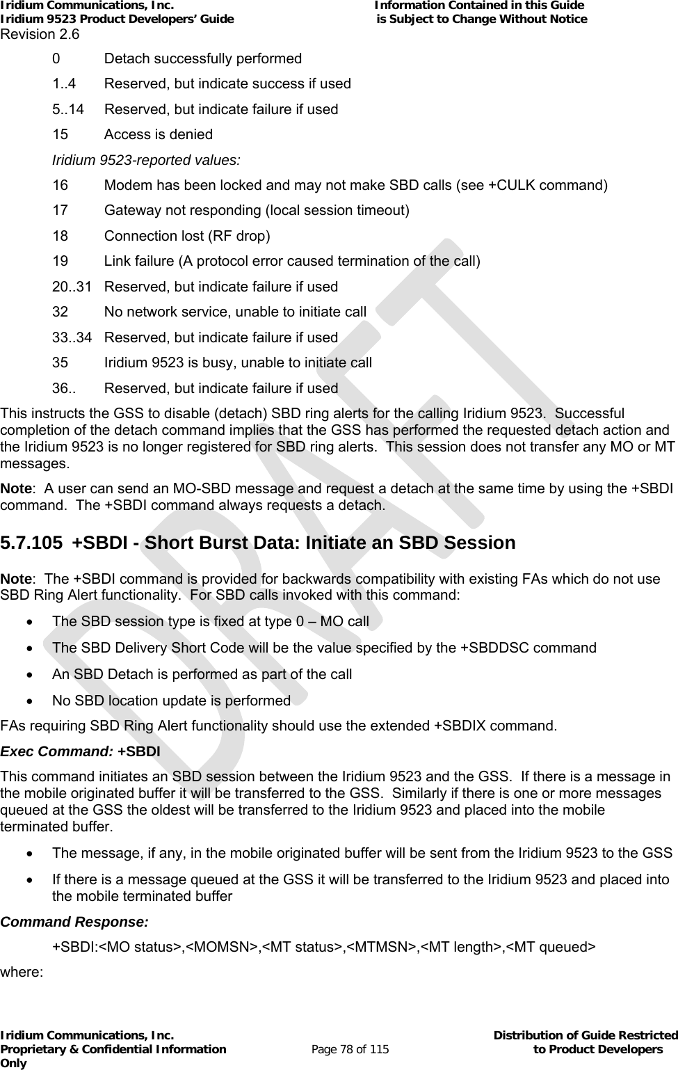
![Iridium Communications, Inc. Information Contained in this Guide Iridium 9523 Product Developers’ Guide is Subject to Change Without Notice Revision 2.6 Iridium Communications, Inc. Distribution of Guide Restricted Proprietary & Confidential Information Page 79 of 115 to Product Developers Only <MO status>: MO session status provides an indication of the disposition of the mobile originated transaction. The field can take on the following values: 0 No SBD message to send from the Iridium 9523 1 SBD message successfully sent from the Iridium 9523 to the GSS 2 An error occurred while attempting to send SBD message from Modem to GSS <MOMSN>: The Mobile Originated Message Sequence Number (MOMSN) is a value assigned by the Iridium 9523 when sending a mobile-originated message to the GSS. This value is incremented each time an SBD session is successfully completed between the Iridium 9523 to the GSS. This wraparound counter can range from 0 to 65535. <MT status>: The MT status provides an indication of the disposition of the mobile terminated transaction. The field can take on the following values: 0 No SBD message to receive from the GSS 1 SBD message successfully received from the GSS 2 An error occurred while attempting to perform a mailbox check or receive a message from the GSS <MTMSN>: The Mobile Terminated Message Sequence Number (MTMSN) is assigned by the GSS when forwarding a message to the Iridium 9523. This value is indeterminate if the field <MT status> is zero. This wraparound counter can range from 0 to 65535. <MT length>: The MT length is the length in bytes of the mobile terminated SBD message received from the GSS. If no message was received, this field will be zero. <MT queued>: MT queued is a count of mobile terminated SBD messages waiting at the GSS to be transferred to the Iridium 9523. 5.7.106 +SBDIX[A] - Short Burst Data: Initiate an SBD Session Extended Note: The +SBDIX command must be used in place of the +SBDI command for FAs wishing to make use of SBD Ring Alert functionality. Exec Command: +SBDIX[A][=<location>] This command initiates an SBD session between the Iridium 9523 and the GSS, setting the SBD Session Type according to the type of command +SBDIX or +SBDIXA, Delivery Short Code according to the value specified by the +SBDDSC command, and the type of location according to whether the optional location value is provided. If there is a message in the mobile originated buffer it will be transferred to the GSS. Similarly if there are one or more messages queued at the GSS the oldest will be transferred to the Iridium 9523 and placed into the mobile terminated buffer. The message, if any, in the mobile originated buffer will be sent from the Iridium 9523 to the GSS If there is a message queued at the GSS it will be transferred to the Iridium 9523 and placed into the mobile terminated buffer](https://usermanual.wiki/Iridium-Satellite/9523/User-Guide-1567636-Page-79.png)
![Iridium Communications, Inc. Information Contained in this Guide Iridium 9523 Product Developers’ Guide is Subject to Change Without Notice Revision 2.6 Iridium Communications, Inc. Distribution of Guide Restricted Proprietary & Confidential Information Page 80 of 115 to Product Developers Only This command will always attempt an SBD registration, consisting of attach and location update, during the SBD session in order to support SBD Ring Alert. If this is not desired, the +SBDI command should be used. The FA should append an ‘A’ to the command, i.e. +SBDIXA, when the SBD session is in response to an SBD ring alert <location> has format: [+|-]DDMM.MMM,[+|-]dddmm.mmm where: DD Degrees latitude (00-89) MM Minutes latitude (00-59) MMM Thousandths of minutes latitude (000-999) ddd Degrees longitude (000-179) mm Minutes longitude (00-59) mmm Thousandths of minutes longitude (000-999) This command initiates an SBD session between the Iridium 9523 and the GSS, setting the SBD Session. The optional sign indicators specify latitude North (+) or South (-), and longitude East (+) or West (-). If omitted, the default is +. For example, AT+SBDIX=5212.483,-00007.350 corresponds to 52 degrees 12.483 minutes North, 0 degrees 7.35 minutes West. Command Response: +SBDIX:<MO status>,<MOMSN>,<MT status>,<MTMSN>,<MT length>,<MT queued> where: <MO status>: MO session status provides an indication of the disposition of the mobile originated transaction. The field can take on the following values: Gateway-reported values: 0 MO message, if any, transferred successfully 1 MO message, if any, transferred successfully, but the MT message in the queue was too big to be transferred 2 MO message, if any, transferred successfully, but the requested Location Update was not accepted 3..4 Reserved, but indicate MO session success if used 5..8 Reserved, but indicate MO session failure if used 10 GSS reported that the call did not complete in the allowed time 11 MO message queue at the GSS is full 12 MO message has too many segments 13 GSS reported that the session did not complete 14 Invalid segment size](https://usermanual.wiki/Iridium-Satellite/9523/User-Guide-1567636-Page-80.png)
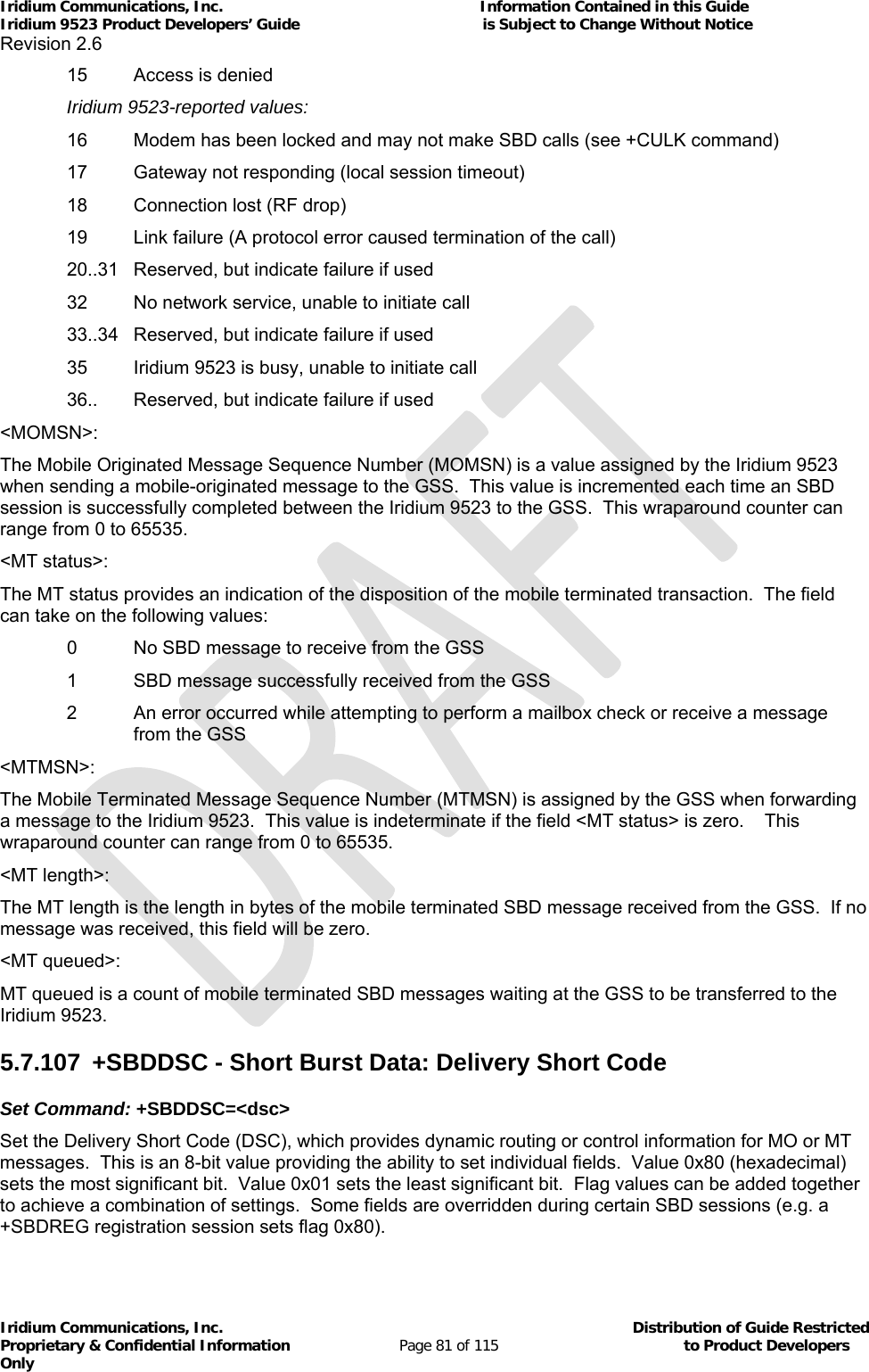
![Iridium Communications, Inc. Information Contained in this Guide Iridium 9523 Product Developers’ Guide is Subject to Change Without Notice Revision 2.6 Iridium Communications, Inc. Distribution of Guide Restricted Proprietary & Confidential Information Page 82 of 115 to Product Developers Only Enable or disable ring indications for SBD Ring Alerts. <dsc>: 0..255 DSC to be used for subsequent MO messages (0 default) 0x80 Hold MT message delivery 0x40 Leave MT message in queue after delivery 0x20 Destination in MO payload Read Command: +SBDDSC? Query the current Delivery Short Code. The response is of the form: +SBDDSC:<dsc> 5.7.108 +SBDMTA - Short Burst Data: Mobile-Terminated Alert Set Command: +SBDMTA=<mode> Enable or disable ring indications for SBD Ring Alerts. <status>: 0 Disable ring indication 1 Enable ring indication (default) When SBD ring indication is enabled, the Iridium 9523 asserts the RI line and issues the unsolicited result code SBDRING when an SBD ring alert is received. Read Command: +SBDMTA? Query the current ring indication mode. The response is of the form: +SBDMTA:<mode> Test Command: +SBDMTA=? List the supported mode settings. The response is of the form: +SBDMTA:(supported <mode> settings) 5.7.109 +SBDREG - Short Burst Data: Network Registration Exec Command: +SBDREG[=<location>] Triggers an SBD session to perform a manual SBD registration. This command initiates an SBD session to perform a manual SBD registration, consisting of an attach and location update. This session does not transfer any MO or MT messages. Note: The Iridium 9523 restricts the number of manual and automatic registrations to one every 3 minutes. Successive attempts within 3 minutes will return an error code indicating that the FA should try later (see error 36 below). Note: A user can send an MO SBD message and register at the same time by using the +SBDIX command. The +SBDIX command always performs a registration attempt and should be used for an application requiring SBD Ring Alert. The +SBDI command never includes an SBD registration and should be used for an application that does not require SBD Ring Alert. <location> has format: [+|-]DDMM.MMM,[+|-]dddmm.mmm where:](https://usermanual.wiki/Iridium-Satellite/9523/User-Guide-1567636-Page-82.png)
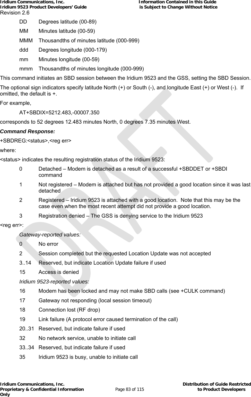
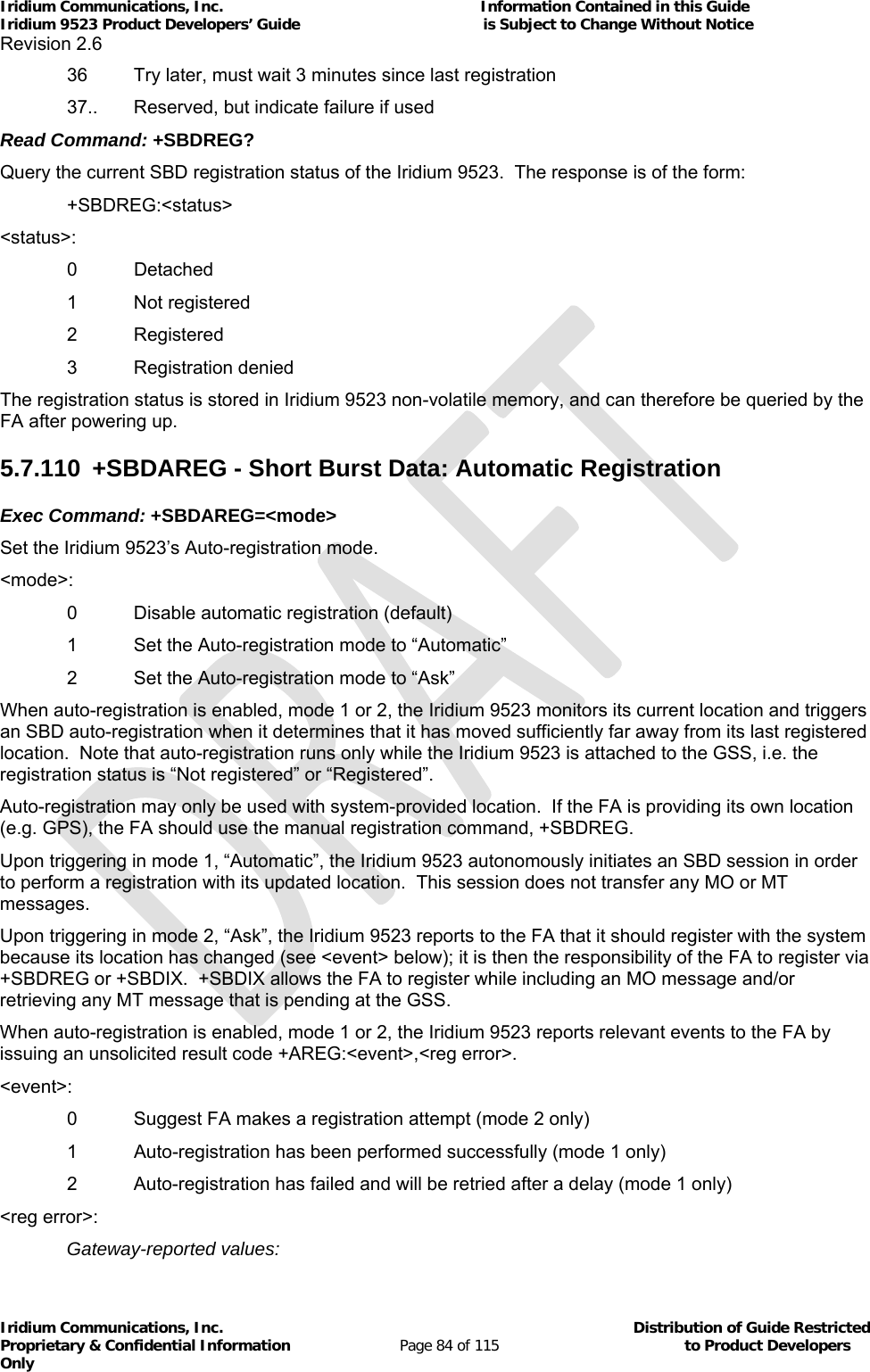
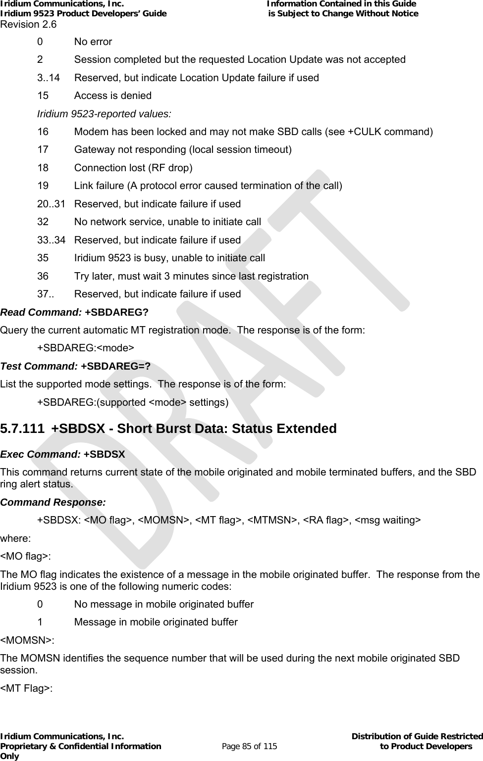
![Iridium Communications, Inc. Information Contained in this Guide Iridium 9523 Product Developers’ Guide is Subject to Change Without Notice Revision 2.6 Iridium Communications, Inc. Distribution of Guide Restricted Proprietary & Confidential Information Page 86 of 115 to Product Developers Only The MT flag indicates the existence of a message in the mobile terminated buffer. The response from the Iridium 9523 is one of the following numeric codes: 0 No message in mobile terminated buffer 1 Message in mobile terminated buffer <MTMSN>: The MTMSN identifies the sequence number that was used in the most recent mobile terminated SBD session. This value will be –1 if there is nothing in the mobile terminated buffer. <RA flag>: The RA flag indicates whether an SBD ring alert has been received and still needs to be answered. 0 No SBD ring alert 1 SBD ring alert has been received and needs to be answered Note: The RA flag is set whenever the Iridium 9523 receives an SBD ring alert; this happens even if the +SBDMTA setting specifies that SBD ring indications are disabled. The RA flag is cleared only on successful completion of an SBD mailbox check, i.e. an SBD session invoked with +SBDI[X[A]] in which the returned MT status indicates that no error occurred. The value of the RA flag is stored in non-volatile memory so it is preserved across power cycling of the Iridium 9523. <msg waiting>: The message waiting flag indicates how many SBD mobile terminated messages are currently queued at the gateway awaiting collection by the Iridium 9523. This flag is updated after every SBD session, including +SBDI, +SBDIX, +SBDIXA, +SBDREG and +SBDDET. 5.7.112 +ADJANT – User Antenna Adjustment Required Exec Command: none Unsolicited Announcement: +ADJANT:<adj_required> where: <adj_required>: The adj_required flag indicates whether the user needs to adjust the L-band antenna position to improve reception. 0 Adjustment no longer required 1 Adjustment required The “+ADJANT:1” message will be sent up to three times, at 5-second intervals, if Layer 1 is attempting to acquire an L-band bearer but is unable to receive the BCCH transmission from the SV, whether the attempt is due to an MT call (prior to RING indication), MO call, or Location Update etc. It is an indication that the user needs to deploy the antenna or adjust it to a better orientation/location. Note that if the acquisition fails or succeeds, there will in most cases be a subsequent “+ADJANT:0”, but this is not guaranteed in all cases. 5.7.113 +WANTST, +ANTST – Antenna status Exec Command:](https://usermanual.wiki/Iridium-Satellite/9523/User-Guide-1567636-Page-86.png)
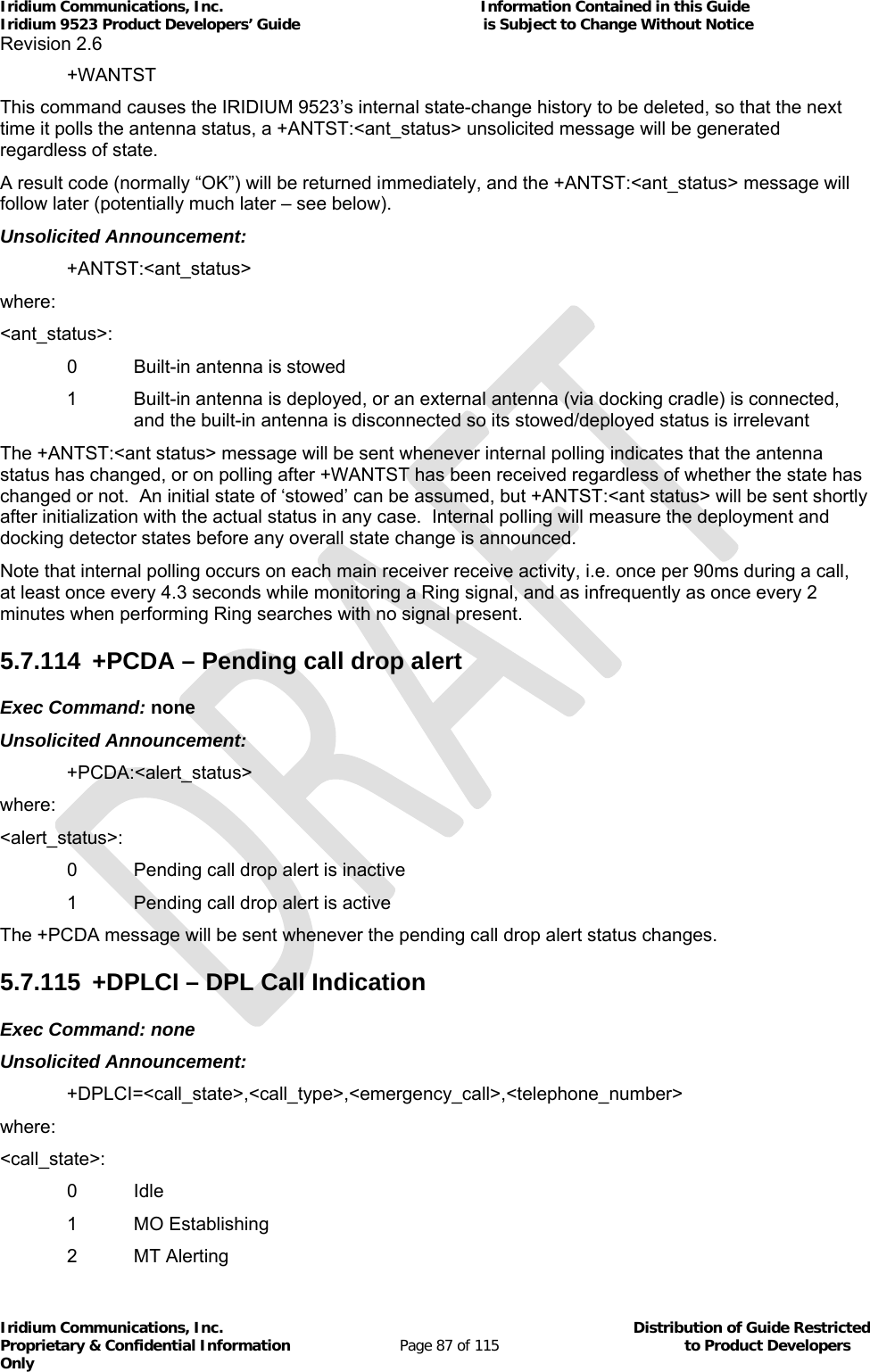
![Iridium Communications, Inc. Information Contained in this Guide Iridium 9523 Product Developers’ Guide is Subject to Change Without Notice Revision 2.6 Iridium Communications, Inc. Distribution of Guide Restricted Proprietary & Confidential Information Page 88 of 115 to Product Developers Only 3 MT Connecting 4 Active 5 Releasing <call_type>: 0 Speech 1 Data <emergency_call>: 0 Normal Call 1 Emergency Call <telephone_number>: Dialed telephone number digits The +DPLCI message will be sent whenever there is a call state change based on the activity of a DPL peripheral handset. 5.7.116 +CCWA - Call Waiting service Command Possible response(s) +CCWA= None (command ignored without error) +CCWA=<n>[,<mode>,<classx>] When command unsuccessful +CME ERROR: <err> When <mode>=2 command successful +CCWA:<status>,<class1> [<CR><LF>+CCWA:<status>,<class2> [...]] (but the Iridium 9523 will in practice only report a single line, <class1> = 1) When <mode> not 2 and command successful None +CCWA? Current unsolicited result presentation status +CCWA:<n> Test command +CCWA=? List of supported <n>s +CCWA:(0,1) None Unsolicited result notifying that a call is waiting +CCWA:<number>,<type>,<class> Note: While this command is implemented in the Iridium 9523, it may not yet be supported in the Iridium network. Stand by for an Iridium Technical Bulletin announcing network support for this feature. This command is based on GSM 07.07 [2] subclause 7.11, and allows control of the Iridium Call Waiting supplementary service similar to GSM 02.83 [6]. Activation, deactivation and status query are supported. Parameter <n> is used to disable/enable the presentation of the unsolicited result code to the FA when the Call Waiting service is enabled.](https://usermanual.wiki/Iridium-Satellite/9523/User-Guide-1567636-Page-88.png)
![Iridium Communications, Inc. Information Contained in this Guide Iridium 9523 Product Developers’ Guide is Subject to Change Without Notice Revision 2.6 Iridium Communications, Inc. Distribution of Guide Restricted Proprietary & Confidential Information Page 89 of 115 to Product Developers Only Command is abortable in the cases when the network is interrogated. The interaction of this command with other commands based on other GSM supplementary services is described in the GSM standard. Defined values <n> (sets/shows the result code presentation status in the Iridium 9523): 0 disable unsolicited result presentation 1 enable unsolicited result presentation On a DTE-DCE command, <n> will set the result code presentation status in the Iridium 9523, regardless of the value of any <mode> parameter. <mode> (when <mode> parameter is not given, network is not interrogated): 0 disable Call Waiting service for specified class(es) 1 enable Call Waiting service for specified class(es) 2 query status of Call Waiting service for specified class(es) <classx> is a sum of integers each representing a class of information: 1 voice 2 data 4 fax This parameter defaults to 7, equal to all classes, but the Iridium 9523 only supports Voice Call Waiting so this is illegal. Therefore in practice the FA must supply <classx>=1. <status>: 0 Call Waiting service not active for specified Class 1 Call Waiting service active for specified Class <number>: quoted string type phone number of calling address in format specified by <type> <type>: type of address octet in integer format (refer GSM 04.08 [7] subclause 10.5.4.7); default 145 when dialing string is international number, otherwise 129. If the network rejects a request to activate/deactivate the Call Waiting service due to it not being provisioned (or for other reasons), the reported CME ERROR code will be 133 “requested service option not subscribed”. This is strictly speaking a GPRS-related code (GSM 07.07 [2] subclause 9.2.2), but is the most informative choice in this case. Informative examples: The status of only the Voice class can be queried: AT+CCWA=1,2,1 If the command is successful, the Iridium 9523 might return (after contacting the network): +CCWA:1,1 If a remote caller tries to place a voice call to the Iridium 9523 while it already has a call in progress, and the Call Waiting service has been made active for class Voice, then the network will send a message to the Iridium 9523. Then, if <n> has previously been set to ‘1’, the Iridium 9523 will send an unsolicited result code to the FA, e.g.: +CCWA:”+441223420024”,145,1](https://usermanual.wiki/Iridium-Satellite/9523/User-Guide-1567636-Page-89.png)
![Iridium Communications, Inc. Information Contained in this Guide Iridium 9523 Product Developers’ Guide is Subject to Change Without Notice Revision 2.6 Iridium Communications, Inc. Distribution of Guide Restricted Proprietary & Confidential Information Page 90 of 115 to Product Developers Only 5.7.117 +CLCK - Facility Lock Command Possible response(s) +CLCK= None (command ignored without error) +CLCK=<fac>,<mode>[<passwd>[,<classx>]] When command unsuccessful +CME ERROR: <err> When <mode>=2 and command successful +CLCK:<status>[,<class1> [<CR><LF>+CLCK:<status>,<class2> [...]] (but the Iridium 9523 will in practice only report a single line, <class1> = 1) When <mode> not 2 and command successful None Test command +CLCK=? List of supported <fac>s +CLCK:(“CS”,”SC”,”FD”,”AO”,”AI”,”AB”) This command is based on GSM 07.07 [2] subclause 7.4, and is used to enable, disable or interrogate an ME or a network facility <fac>. Command is abortable in the cases when network facilities are set or interrogated. The interaction of this command with other commands based on other GSM supplementary services is described in the GSM standard. Execute command is used to activate or deactivate Call Barring Supplementary Services, SIM Fixed Dialling feature, the SIM card PIN Code, or to enable or disable the Phone Lock feature in the Iridium 9523. A password code (detailed below) may be required, depending on the action chosen. Not all Call Barring services detailed in GSM 07.07 [2] subclause 7.4 are supported. A subset of those implemented in the H1 menu MMI is supported. Note: This command will not work unless the SIM PIN has been entered using the +CPIN command. Note: Once this command has been issued to disable the PIN, neither it nor the +CPIN need to be issued again unless the PIN function is reactivated. The following parameter values are currently supported: <fac>: “CS” CNTRL Surface (Enable/Disable Phone Lock feature). The current Phone Unlock Code is required as <passwd>. “SC” SIM: Activate/Deactivate SIM card PIN Code, in which the SIM asks password in ME power-up. The PIN code is required as <passwd>. "FD" SIM fixed dialling memory feature (PIN2 is required as <passwd>) "AO" BAOC (Bar All Outgoing Calls) (refer GSM 02.88 [4] clause 1). The Call Barring password is required as <passwd>. "AI" BAIC (Bar All Incoming Calls) (refer GSM 02.88 [4] clause 2). The Call Barring password is required as <passwd>. "AB" All Barring services (refer GSM 02.30 [5]) (applicable only for <mode>=0). The Call Barring password is required as <passwd>.](https://usermanual.wiki/Iridium-Satellite/9523/User-Guide-1567636-Page-90.png)
![Iridium Communications, Inc. Information Contained in this Guide Iridium 9523 Product Developers’ Guide is Subject to Change Without Notice Revision 2.6 Iridium Communications, Inc. Distribution of Guide Restricted Proprietary & Confidential Information Page 91 of 115 to Product Developers Only Note: several GSM standard facility codes including the following are NOT supported: "OI" BOIC (Bar Outgoing International Calls) (refer GSM 02.88 [4] clause 1). All Iridium calls are International, so this facility should not be exercised by a user interface. "OX" BOIC-exHC (Bar Outgoing International Calls except to Home Country) (refer GSM 02.88 [4] clause 1). All Iridium calls are International, so this facility should not be exercised by a user interface. "IR" BIC-Roam (Bar Incoming Calls when Roaming outside the home country) (refer GSM 02.88 [4] clause 2). In Iridium it is not possible to roam (there is only one “home country”), so this facility should not be exercised by a user interface. "AG" All outGoing barring services (refer GSM 02.30 [5]) (applicable only for <mode>=0). This subgroup of services cannot be addressed; the user interface should just use “AB”. "AC" All inComing barring services (refer GSM 02.30 [5]) (applicable only for <mode>=0). This subgroup of services cannot be addressed; the user interface should just use “AB”. <mode>: 0 Disable (Deactivate) 1 Enable (Activate) <passwd>: string type, enclosed by “ “; for example, “1234”. Note: Factory default SIM card PIN Code is “1111” Note: Factory default Phone Unlock Code is “1234” <classx> is a sum of integers each representing a class of information: 1 voice 2 data 4 fax This parameter defaults to 7, equal to all classes, but the Iridium 9523 only supports Voice Call Barring so this is illegal. Therefore in practice the FA must supply <classx>=1 when querying or changing the status of any Call Barring facility. When querying (<mode>=2), <passwd> is irrelevant and should be supplied as ”” in order to allow the <classx>=1 parameter to be supplied. For facilities “CS”, “SC”and “FD”, the <passwd> and <classx> parameters are not relevant and will be ignored if supplied. Test Command: +CLCK=? Test command returns the facility values supported by the phone. The response is in the form: +CLCK:(list of supported <fac>s) Note: Only “CS” will appear as a supported value if there is no SIM card in the device. Note: +CLCK is closely related to +CPIN and +CPWD. See these commands for additional information. 5.7.118 +CPWD - Change Password Exec Command: +CPWD=<fac>,<oldpwd>,<newpwd> This command sets a new password for the facility lock function defined by the AT command Facility Lock +CLCK . The following parameter values are currently supported: <fac>: “CS” CNTRL Surface (Phone Unlock Code)](https://usermanual.wiki/Iridium-Satellite/9523/User-Guide-1567636-Page-91.png)
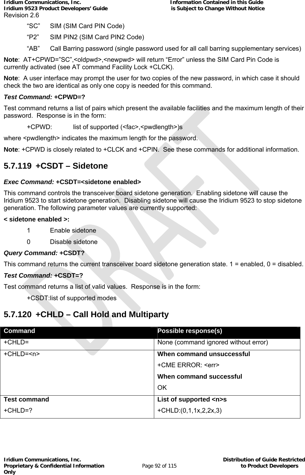
![Iridium Communications, Inc. Information Contained in this Guide Iridium 9523 Product Developers’ Guide is Subject to Change Without Notice Revision 2.6 Iridium Communications, Inc. Distribution of Guide Restricted Proprietary & Confidential Information Page 93 of 115 to Product Developers Only Note: While this command is implemented in the Iridium 9523, it may not yet be supported in the Iridium network. Stand by for an Iridium Technical Bulletin announcing network support for this feature. This command is based on GSM 07.07 [2] subclause 7.12, and is used to invoke the HOLD and MPTY supplementary services for switching between held calls, etc. The values of <n> are the same as those that a user can enter via a numeric keypad, as described in GSM 02.30 [5] subclause 4.5.5. This command is not abortable, and finishes without waiting for a response from the network. The interaction of this command with other commands based on other GSM supplementary services is described in the GSM standard. The following parameter values are currently supported: <n>: “0” Releases all held calls or sets User Determined User Busy (UDUB) for a waiting call “1” Releases all active calls (if any exist) and accepts the other (held or waiting) call “1X” Releases a specific active call X “2” Places all active calls (if any exist) on hold and accepts the other (held or waiting) call “2X” Places all active calls on hold except call X with which communication shall be supported “3” Adds a held call to the conversation “4” Not supported (Connects the two calls and disconnects the subscriber from both calls (ECT)) “4*dirno” Not supported (Redirect an incoming or a waiting call to the specified directory number) “5” Not supported ($(CCBS)$: Activates the Completion of Calls to Busy Subscriber Request) Test Command: +CHLD=? Test command returns the <n> values supported by the phone. The response is in the form: +CHLD:(list of supported <n>s) Note: “AT+CHLD=0” can be used to set UDUB when there is an incoming call, whether or not there is a current call active (or held), in order to support GSM 02.30 [5] subclauses 4.4.2.3 and 4.5.5.2. 5.7.121 +XCSI – Extended Call State Information This proprietary unsolicited announcement was added to allow the FA to keep track of call state during Call Hold and Multiparty operations using AT+CHLD. Exec Command: none Unsolicited Announcement: +XCSI=<overall call_state>,<active call_state>,<held_call state>,<active index>,<held index> where: <overall call_state>: 0 Idle (dialling possible) 1 One single-party call active 2 One multiparty call active 3 Incoming call arriving (otherwise idle) 4 One single-party call active, plus waiting call](https://usermanual.wiki/Iridium-Satellite/9523/User-Guide-1567636-Page-93.png)
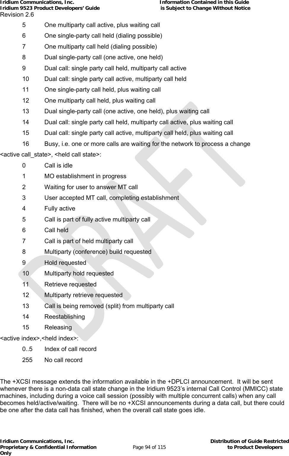
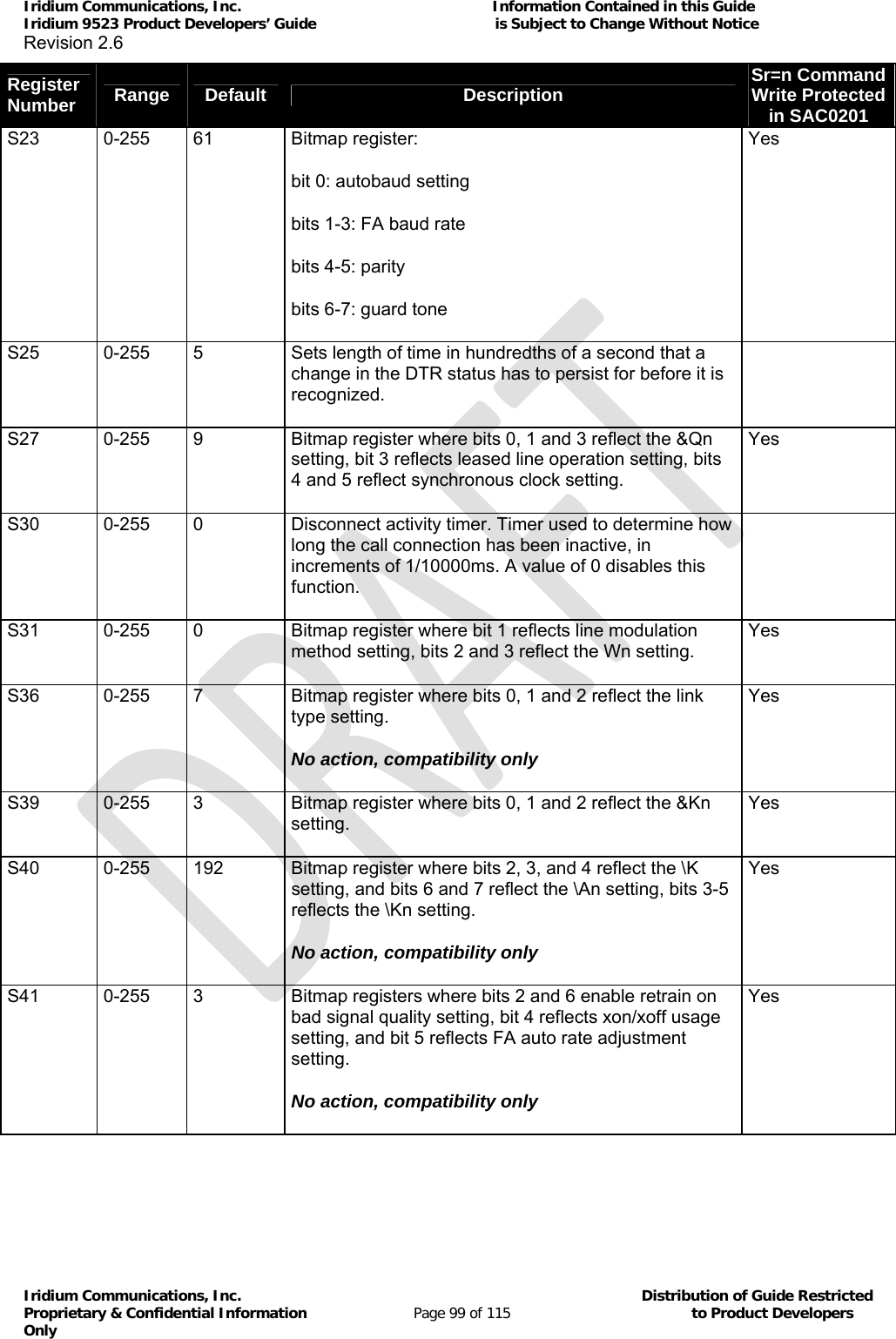
![Iridium Communications, Inc. Information Contained in this Guide Iridium 9523 Product Developers’ Guide is Subject to Change Without Notice Revision 2.6 Iridium Communications, Inc. Distribution of Guide Restricted Proprietary & Confidential Information Page 100 of 115 to Product Developers Only Register Number Range Default Description Sr=n Command Write Protected in SAC0201 S95 0-255 0 Bitmap register for extended result codes (overrides Wn setting). 0 = CONNECT shows DCE speed 2 = Enable CARRIER XXXX 3 = Enable PROTOCOL: XXXX 5 = Enable COMPRESSION: XXXX 6.3 Iridium Specific S-Register Extensions Table 17: Iridium-Specific S-Registers Register Number Range Default Description Sr=n Command Write Protected in SAC0201 S13 0-255 0 Bitmap register where bits 0-1 reflect the DCE data bits, bits 2-3 reflect the DCE stop bits, bits 4-6 reflect the DCE parity settings, and bit 7 is not used Yes S15 0-2 0 Auto-answer mode selection Bits 0-1: 0 (auto-answer voice and data calls) 1 (auto-answer voice calls only) 2 (auto-answer data calls only) S34 0-255 0 Bitmap register where bit 7 reflects the +DR setting, bits 0-1 reflect the data compression type (PT), bit 6 reflects the +DS compression negotiation setting. Yes S35 0-255 5 Bearer service capabilities S42 0-255 0 GSM Call clearing code as returned by the network. Refer to GSM 04.08 [7] Table 10.86 Cause Information Element Values. Yes S43 0-255 32 Bitmap register: 0 = +CMGF setting 1 = +CBST parameter <name> setting 2 = +CMEE setting 3 = +CMEE setting Yes](https://usermanual.wiki/Iridium-Satellite/9523/User-Guide-1567636-Page-100.png)
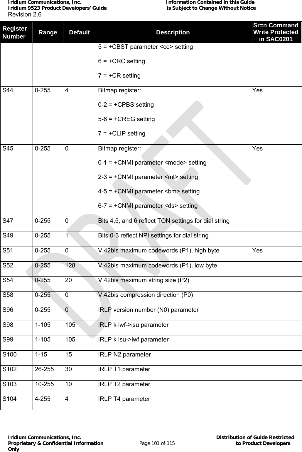
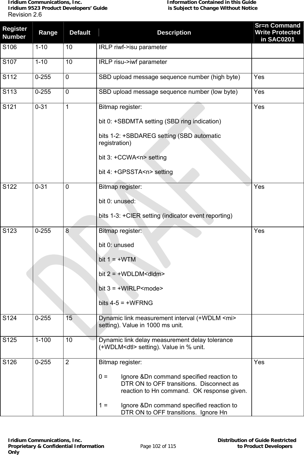
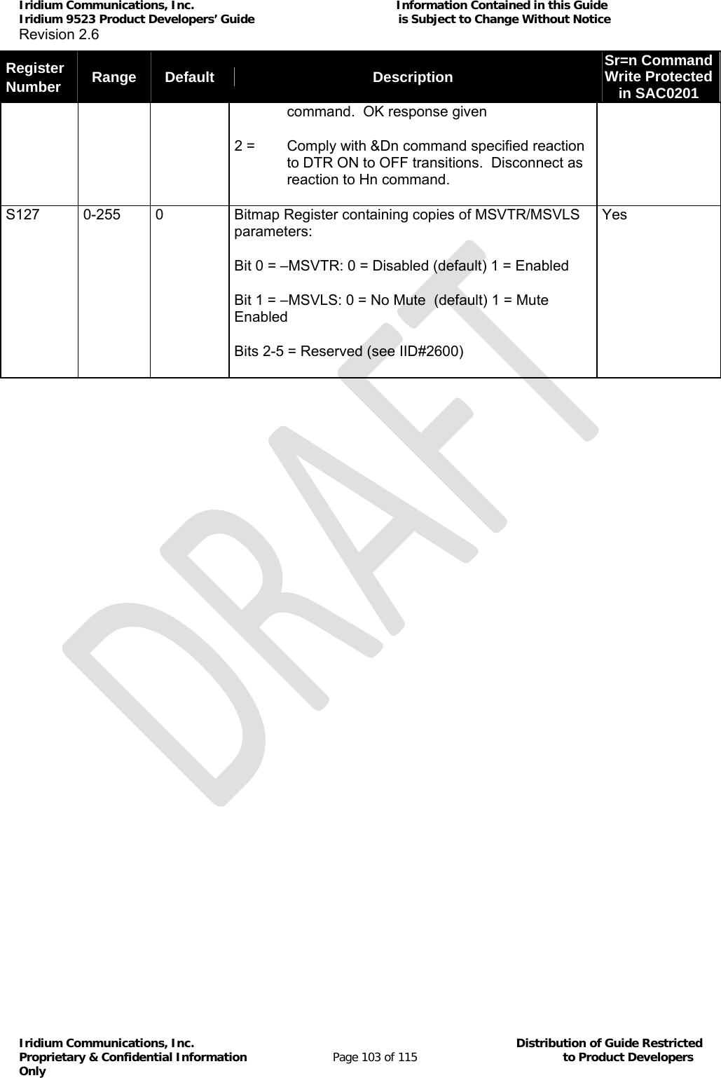
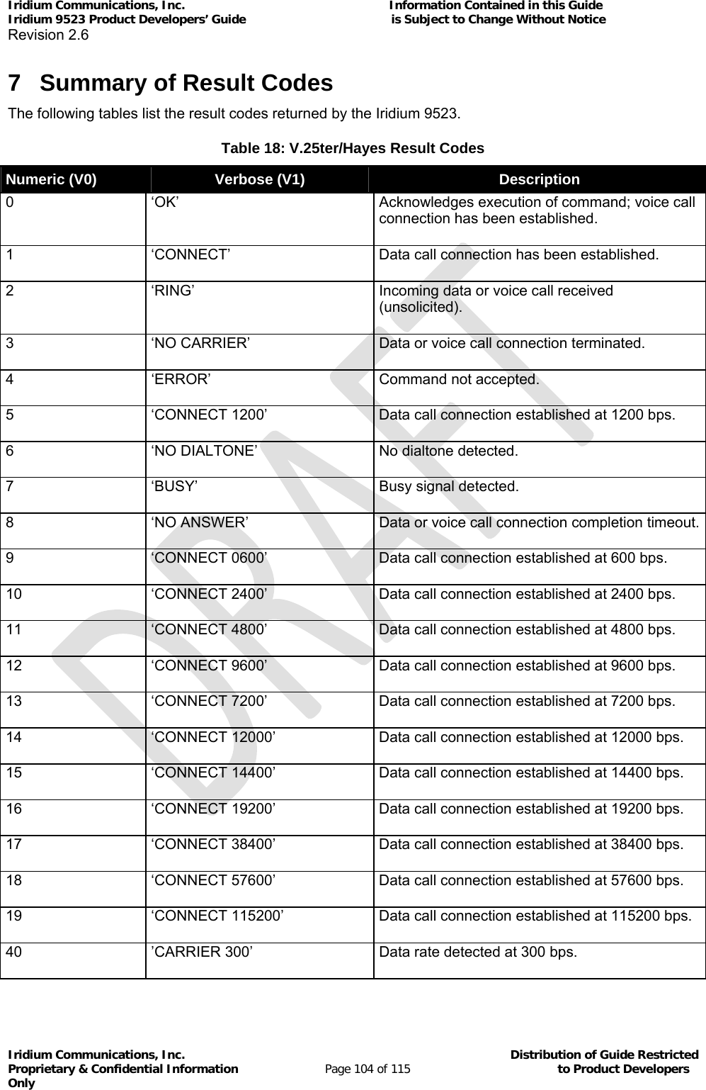
![Iridium Communications, Inc. Information Contained in this Guide Iridium 9523 Product Developers’ Guide is Subject to Change Without Notice Revision 2.6 Iridium Communications, Inc. Distribution of Guide Restricted Proprietary & Confidential Information Page 105 of 115 to Product Developers Only 44 ’CARRIER 1200/75 ‘ Data rate detected at V.23 backward channel. 46 ’CARRIER 1200’ Data rate detected at 1200 bps. 47 ’CARRIER 2400’ Data rate detected at 2400 bps. 48 ’CARRIER 4800’ Data rate detected at 4800 bps. 49 ’CARRIER 7200’ Data rate detected at 7200 bps. 50 ’CARRIER 9600’ Data rate detected at 9600 bps. 51 ’CARRIER 12000’ Data rate detected at 12000 bps. 67 ‘COMPRESSION: V.42bis’ Data call connected with V.42bis compression enabled. 69 ‘COMPRESSION: NONE’ Data call connected with no data compression. 126 ‘SBDRING’ SBD ring alert received, indicating presence of a mobile terminated SBD message at gateway. 127 ‘HARDWARE FAILURE: <subsys>,<error>’ Issued at initialization in case of a hardware failure. See section Error! Reference source not found. as verbose ‘+DR: V42B NONE’ Data call connected with no data compression. as verbose ‘+DR: V42B TD’ Data call connected with V.42bis compression enabled on transmit direction. as verbose ‘+DR: V42B RD’ Data call connected with V.42bis compression enabled on receive direction. as verbose ‘+DR: V42B’ Data call connected with V.42bis compression enabled on both transmit and receive direction. Table 19: GSM 7.07 Result Codes Numeric (V0) Verbose (V1)Description as verbose ‘+CR: ASYNC’ Asynchronous transparent data connection as verbose ‘+CR: REL ASYNC’ Asynchronous non-transparent data ias verbose ‘+CME ERROR: <error> Command not accepted. See section 5.7.28. as verbose ‘+CREG: <stat>[,<lac>,<ci>] Registration indication status (unsolicited if enabled). See section 5.7.50. as verbose ‘+CRING: ASYNC‘ Asynchronous transparent data call indication as verbose ‘+CRING: REL ASYNC‘ Asynchronous non-transparent data ias verbose ‘+CRING: VOICE‘ Voice call connection](https://usermanual.wiki/Iridium-Satellite/9523/User-Guide-1567636-Page-105.png)
![Iridium Communications, Inc. Information Contained in this Guide Iridium 9523 Product Developers’ Guide is Subject to Change Without Notice Revision 2.6 Iridium Communications, Inc. Distribution of Guide Restricted Proprietary & Confidential Information Page 106 of 115 to Product Developers Only Table 20: GSM 7.05 Result Codes Numeric Verbose (V1)Description as verbose ‘+CMTI: <mem>,<index>’ SMS-DELIVER message indication (unsolicited if enabled). See section 5.7.42. as verbose ‘+CMT: [<alpha>],<length><CR><LF><pdu>’ (PDU mode) SMS-DELIVER message indication (unsolic-ited if enabled). See section 5.7.42. as verbose ‘+CDS:<length><CR><LF><pdu>’ (PDU mode) SMS-STATUS-REPORT message indication (unsolicited if enabled). See section 5.7.42. as verbose ‘+CMS ERROR: <error> SMS command failed. See section 5.7.35. Table 21: Iridium-specific Result Codes Numeric (V0) Verbose (V1)Description as verbose ‘READY’ Ready to receive SBD binary message data from FA. See section 5.7.85. as verbose ‘+AREG:<event>,<reg error>’ Auto-registration event report. See section 5.7.110. as verbose ‘+CIEV:<sig><value>’ Indicator event report. See section 5.7.94. as verbose '+ADJANT:<deployed>' User antenna adjustment is required. See section 5.7.112.](https://usermanual.wiki/Iridium-Satellite/9523/User-Guide-1567636-Page-106.png)
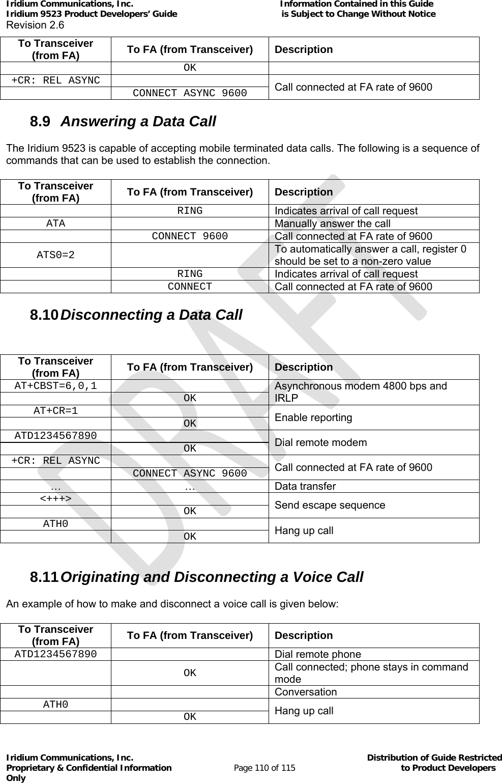
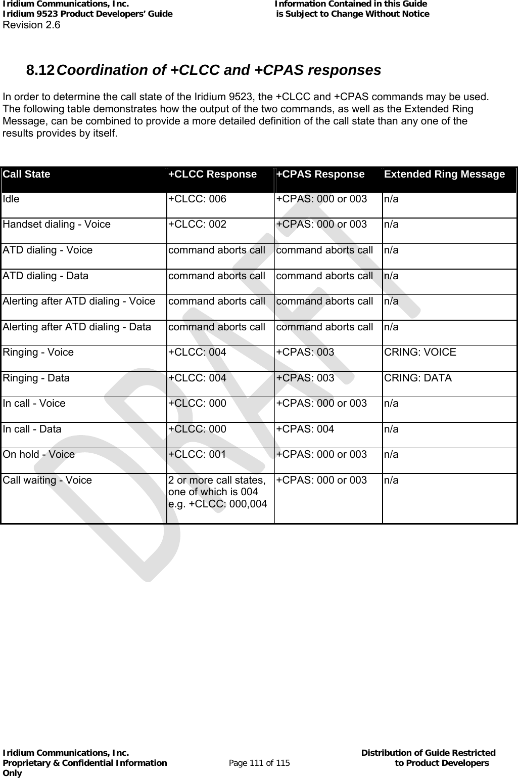
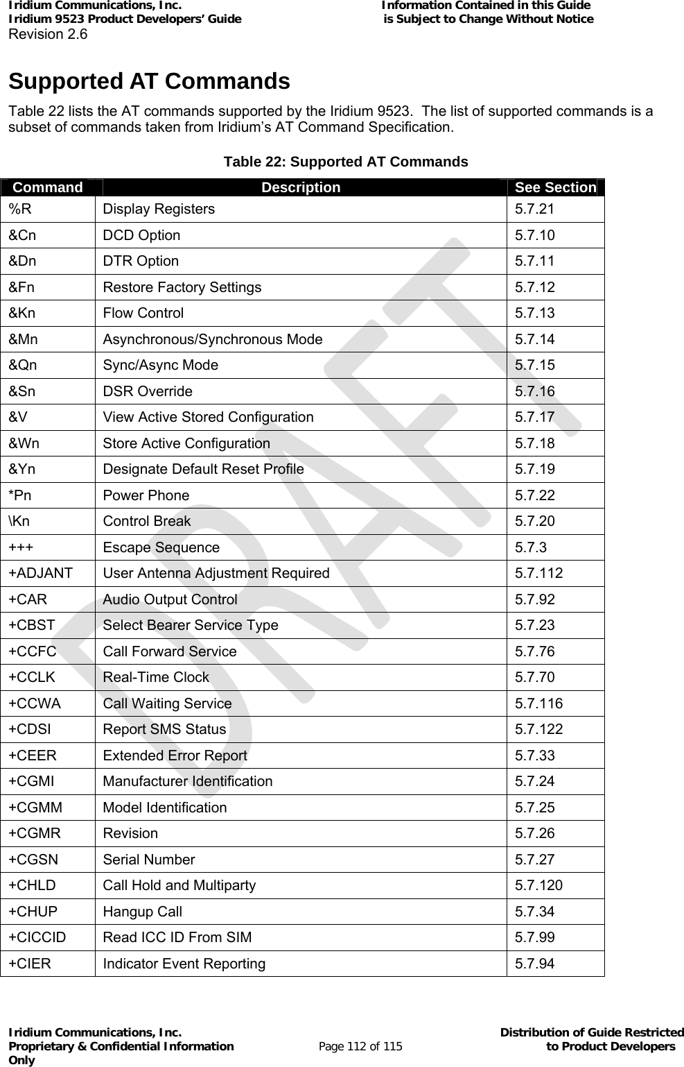
![Iridium Communications, Inc. Information Contained in this Guide Iridium 9523 Product Developers’ Guide is Subject to Change Without Notice Revision 2.6 Iridium Communications, Inc. Distribution of Guide Restricted Proprietary & Confidential Information Page 113 of 115 to Product Developers Only Command Description See Section +CLCC Request Current Call Status 5.7.77 +CLCK Facility Lock 5.7.117 +CLIP Calling Line Identification Presentation 5.7.100 +CLIR Calling Line Identification Restriction 5.7.101 +CLVL Loudspeaker Volume Level Control 5.7.66 +CMEE Report Mobile Equipment Error 5.7.28 +CMGD Delete SMS Message 5.7.35 +CMGF SMS Message Format 5.7.36 +CMGL List SMS Messages 5.7.37 +CMGR Read SMS Message 5.7.38 +CMGS Send SMS Message 5.7.39 +CMGW Write SMS Message To Memory 5.7.40 +CMOD Call Mode 5.7.41 +CMUT Mute Control 5.7.67 +CNMI New SMS Message Indications to DTE 5.7.42 +CNUM Read MSISDN Numbers 5.7.78 +COPS Operator Select 5.7.43 +CPAS Phone Activity Status 5.7.29 +CPBF Find Phonebook Entries 5.7.44 +CPBR Read Phonebook Entries 5.7.45 +CPBS Select Phonebook Storage 5.7.46 +CPBW Write Phonebook Entry 5.7.47 +CPIN Enter PIN 5.7.48 +CPMS Select Preferred SMS Message Storage 5.7.49 +CPWD Change Password 5.7.118 +CR Service Reporting Control 5.7.30 +CRC Cellular Result Codes 5.7.68 +CREG Network Registration 5.7.50 +CRIS Ring Indication Status 5.7.95 +CSCA SMS Service Center Address 5.7.51 +CSCB Select Cell Broadcast Message Types 5.7.52 +CSCS Select TE Character Set 5.7.53 +CSDT Sidetone 5.7.119 +CSMS Select SMS Message Service 5.7.54 +CSQ[F] Signal Quality 5.7.96](https://usermanual.wiki/Iridium-Satellite/9523/User-Guide-1567636-Page-113.png)
![Iridium Communications, Inc. Information Contained in this Guide Iridium 9523 Product Developers’ Guide is Subject to Change Without Notice Revision 2.6 Iridium Communications, Inc. Distribution of Guide Restricted Proprietary & Confidential Information Page 114 of 115 to Product Developers Only Command Description See Section +CSSSC Supplementary Services Short Code 5.7.79 +CSTA Select Type of Address 5.7.55 +CULK Unlock 5.7.97 +CVHU Voice Hangup Control 5.7.69 +CVMI Voicemail Indication 5.7.98 +DPLCI DPL Call Indication 5.7.115 +DR Data Compression Report Level 5.7.32 +DS Set Data Compression Function 5.7.31 +GCAP General Capabilities 5.7.60 +GMI Manufacturer Identification 5.7.56 +GMM Model Identification 5.7.57 +GMR Revision 5.7.58 +GPSSTA Configure GPS Status 5.7.123 +GSN Serial Number 5.7.59 +IPR Fixed DTE Rate 5.7.102 +PCDA Pending Call Drop Alert 5.7.114 +SBDAREG Short Burst Data: Automatic Registration 5.7.110 +SBDC Short Burst Data: Clear SBD MOMSN 5.7.89 +SBDD Short Burst Data: Clear SBD Message Buffer(s) 5.7.88 +SBDDET Short Burst Data: Detach 5.7.104 +SBDDSC Short Burst Data: Delivery Short Code 5.7.107 +SBDI Short Burst Data: Initiate an SBD Session 5.7.105 +SBDIX[A] Short Burst Data: Initiate an SBD Session Extended 5.7.106 +SBDMTA Short Burst Data: Mobile-Terminated Alert 5.7.108 +SBDRB Short Burst Data: Read Binary Data from Iridium 9523 5.7.86 +SBDREG Short Burst Data: Network Registration 5.7.109 +SBDRT Short Burst Data: Read a Text Message from the Iridium 9523 5.7.87 +SBDS Short Burst Data: Status 5.7.90 +SBDSX Short Burst Data: Status Extended 5.7.111 +SBDTC Short Burst Data: Transfer MO Buffer to MT Buffer 5.7.91 +SBDWB Short Burst Data: Write Binary Data to the Iridium 9523 5.7.85 +SBDWT Short Burst Data: Write a Text Message to the Iridium 9523 5.7.103 +WANTST Antenna Status 5.7.113 +WDAV Register or Deregister an RS232 DAV Data Peripheral 5.7.84 +WDLDM IRLP Dynamic Link Delay Measurement 5.7.83](https://usermanual.wiki/Iridium-Satellite/9523/User-Guide-1567636-Page-114.png)