Iridium Satellite 9523 9523 Voice and Data Transceiver Module User Manual 9523 Developer s Guide v2 6
Iridium Satellite LLC 9523 Voice and Data Transceiver Module 9523 Developer s Guide v2 6
manual
Iridium 9523 Product Developers’ Guide
(PRELIMINARY DRAFT)
Iridium Communications, Inc.
Proprietary & Confidential Information

Iridium Communications, Inc. Information Contained in this Guide
Iridium 9523 Product Developers’ Guide is Subject to Change Without Notice
Revision 2.6
Iridium Communications, Inc. Distribution of Guide Restricted
Proprietary & Confidential Information Page 2 of 115 to Product Developers
Only
LEGAL DISCLAIMER AND CONDITIONS OF USE
This document contains information for the Iridium 9523 (“Product”) and is provided “as is.” The purpose
of providing such information is to enable Value Added Resellers and Value Added Manufacturers
(collectively, “Product Developer(s)”) to understand the Product and how to integrate it into a wireless
solution. Reasonable effort has been made to make the information in this document reliable and
consistent with specifications, test measurements and other information. However, Iridium
Communications Inc. and its affiliated companies, directors, officers, employees, agents, trustees or
consultants (“Iridium”) assume no responsibility for any typographical, technical, content or other
inaccuracies in this document. Iridium reserves the right in its sole discretion and without notice to you to
change Product specifications and materials and/or revise this document or withdraw it at any time. The
Product Developer assumes the full risk of using the Product specifications and any other information
provided.
IRIDIUM MAKES NO REPRESENTATIONS, GUARANTEES, CONDITIONS OR WARRANTIES,
EITHER EXPRESS OR IMPLIED, INCLUDING WITHOUT LIMITATION, ANY IMPLIED
REPRESENTATIONS, GUARANTEES, CONDITIONS OR WARRANTIES OF MERCHANTABILITY
AND FITNESS FOR A PARTICULAR PURPOSE, NON-INFRINGEMENT, SATISFACTORY QUALITY,
NON-INTERFERENCE, ACCURACY OF INFORMATIONAL CONTENT, OR ARISING FROM A
COURSE OF DEALING, LAW, USAGE, OR TRADE PRACTICE, USE, OR RELATED TO THE
PERFORMANCE OR NONPERFORMANCE OF ANY PRODUCTS, ACCESSORIES, FACILITIES OR
SERVICES OR INFORMATION EXCEPT AS EXPRESSLY STATED IN THIS GUIDE AND/OR THE
PRODUCT AND/OR SATELLITE SERVICE DOCUMENTATION. ANY OTHER STANDARDS OF
PERFORMANCE, GUARANTEES, CONDITIONS AND WARRANTIES ARE HEREBY EXPRESSLY
EXCLUDED AND DISCLAIMED TO THE FULLEST EXTENT PERMITTED BY LAW. THIS
DISCLAIMER AND EXCLUSION SHALL APPLY EVEN IF THE EXPRESS LIMITED WARRANTY
CONTAINED IN THIS GUIDE OR SUCH DOCUMENTATION FAILS OF ITS ESSENTIAL PURPOSE.
IN NO EVENT SHALL IRIDIUM BE LIABLE, WHETHER IN CONTRACT OR TORT OR ANY OTHER
LEGAL THEORY, INCLUDING WITHOUT LIMITATION STRICT LIABILITY, GROSS NEGLIGENCE OR
NEGLIGENCE, FOR ANY DAMAGES IN EXCESS OF THE PURCHASE PRICE OF THE PRODUCT,
INCLUDING ANY DIRECT, INDIRECT, INCIDENTAL, SPECIAL OR CONSEQUENTIAL DAMAGES OF
ANY KIND, OR LOSS OF REVENUE OR PROFITS, LOSS OF BUSINESS, LOSS OF PRIVACY, LOSS
OF USE, LOSS OF TIME OR INCONVENIENCE, LOSS OF INFORMATION OR DATA, SOFTWARE
OR APPLICATIONS OR OTHER FINANCIAL LOSS CAUSED BY THE PRODUCT (INCLUDING
HARDWARE, SOFTWARE AND/OR FIRMWARE) AND/OR THE IRIDIUM SATELLITE SERVICES, OR
ARISING OUT OF OR IN CONNECTION WITH THE ABILITY OR INABILITY TO USE THE PRODUCT
(INCLUDING HARDWARE, SOFTWARE AND/OR FIRMWARE) AND/OR THE IRIDIUM SATELLITE
SERVICES TO THE FULLEST EXTENT THESE DAMAGES MAY BE DISCLAIMED BY LAW AND
WHETHER ADVISED OF THE POSSIBILITIES OF SUCH DAMAGES. IRIDIUM IS NOT LIABLE FOR
ANY CLAIM MADE BY A THIRD PARTY OR MADE BY YOU FOR A THIRD PARTY.
Your use of the information contained in this Guide is restricted to the development activity
authorized under the agreement(s) between you and Iridium, and is otherwise subject to all
applicable terms and conditions of such agreement(s), including without limitation software
license, warranty, conditions of use and confidentiality provisions.
Export Compliance Information
This Product is controlled by the export laws and regulations of the United States of America. The U.S.
Government may restrict the export or re-export of this Product to certain individuals and/or destinations.
For further information, contact the U.S. Department of Commerce, Bureau of Industry and Security or
visit www.bis.doc.gov.

Iridium Communications, Inc. Information Contained in this Guide
Iridium 9523 Product Developers’ Guide is Subject to Change Without Notice
Revision 2.6
Iridium Communications, Inc. Distribution of Guide Restricted
Proprietary & Confidential Information Page 3 of 115 to Product Developers
Only
Revision History
Revision Date Comment
1.0 Apr 6, 2011 First Draft
2.0 May 9, 2011 Second Draft Following Internal Review
2.3 Jul 26, 2011 Revision sent with Alpha prototype Developer’s Kit
2.5 Sep 12, 2011 Revision sent with Beta prototype Developer’s Kit
2.6 Oct 11, 2011 - Added FCC and IC warning statements (sections 1.3 and 1.4)
- Removed reference to mounting screws in section 2.1 “Dimensions
and Layout”
- Clarified screw/hole specifications in section 2.2 “Field Application
Board Mounting”
- Unified formatting of examples and removed references to AT*Rn in
section 8 “Informative Examples”
Export Compliance Information
This product is controlled by the export laws and regulations of the United States of America. The U.S.
Government may restrict the export or re-export of this product to certain individuals and/or destinations.
For further information, contact the U.S. Department of Commerce, Bureau of Industry and Security or
visit www.bis.doc.gov.

Iridium Communications, Inc. Information Contained in this Guide
Iridium 9523 Product Developers’ Guide is Subject to Change Without Notice
Revision 2.6
Iridium Communications, Inc. Distribution of Guide Restricted
Proprietary & Confidential Information Page 4 of 115 to Product Developers
Only
Contents
Revision History .......................................................................................................................................... 3
C on te nt s ..................................................................................................................................................... 4
List of Abbreviations .................................................................................................................................. 8
1Product Overview ............................................................................................................................... 9
1.1Key Features .......................................................................................................................... 9
1.2Iridium 9523 Packaging and Regulatory Certification ............................................................ 9
1.3FCC Warning Statement ...................................................................................................... 10
1.4Industry Canada Warning Statement ................................................................................... 10
1.4.1English ................................................................................................................................. 10
1.4.2French .................................................................................................................................. 10
1.5Software Revision ................................................................................................................ 11
1.6Reference ............................................................................................................................. 11
2Physical Specification ..................................................................................................................... 13
2.1Dimensions and Layout ....................................................................................................... 14
2.2Field Application Board Mounting ........................................................................................ 15
2.3Environmental ...................................................................................................................... 18
2.3.1Environmental Specification ................................................................................................. 18
2.3.2Environmental Tests Performed .......................................................................................... 18
3Electrical Interfaces ......................................................................................................................... 19
3.1User Connector .................................................................................................................... 19
3.1.1User Connector Type ........................................................................................................... 19
3.1.2User Connector Pin Allocation ............................................................................................. 20
3.2DC Power Supply Interface .................................................................................................. 22
3.2.1Battery Power Input, VBAT .................................................................................................. 22
3.2.2Boost Power Input, VBOOST ............................................................................................... 22
3.2.3Power On/Off Control, TRX_ON .......................................................................................... 22
3.2.4Typical Power Usage Profile ................................................................................................ 22
3.3PCM Digital Audio ................................................................................................................ 24
3.3.1Port 1 .................................................................................................................................... 25
3.3.2Port 2 .................................................................................................................................... 25
3.3.311Hz Signal for Manufacturing and Regulatory Testing ...................................................... 25
3.4DPL port ............................................................................................................................... 26
3.5Data/Fax port ....................................................................................................................... 26
3.5.19-Wire and 3-Wire Operation ............................................................................................... 26
3.5.2Configuration Settings .......................................................................................................... 27
3.5.3Modes of Operation ............................................................................................................. 28
3.5.4Serial port signal levels ........................................................................................................ 28
3.6SIM interface ........................................................................................................................ 28
3.7GPIO Signals ....................................................................................................................... 28
3.7.1Transmit power Control ........................................................................................................ 29
3.7.2External GPS Receiver Switch ............................................................................................ 29
3.7.3Modem/Handset Mode Select Signal................................................................................... 29
4RF Interface ....................................................................................................................................... 30
4.1RF Connector Type .............................................................................................................. 30
4.1.1Antenna Characteristics ....................................................................................................... 30
4.2RF Interface Specifications .................................................................................................. 30
4.3Radio Characteristics ........................................................................................................... 31
4.4S-meter Performance ........................................................................................................... 31
5AT Interface ....................................................................................................................................... 32
5.1Command Types .................................................................................................................. 32
5.2Basic Commands ................................................................................................................. 32

Iridium Communications, Inc. Information Contained in this Guide
Iridium 9523 Product Developers’ Guide is Subject to Change Without Notice
Revision 2.6
Iridium Communications, Inc. Distribution of Guide Restricted
Proprietary & Confidential Information Page 5 of 115 to Product Developers
Only
5.3Extended Commands .......................................................................................................... 32
5.4Command and Response Characters.................................................................................. 33
5.5Command Entry ................................................................................................................... 34
5.6Command Responses ......................................................................................................... 35
5.6.1Hardware Failure Reporting ................................................................................................. 35
5.7Command Set Description ................................................................................................... 36
5.7.1AT - Attention Code ............................................................................................................. 36
5.7.2A/ - Repeat Last Command ................................................................................................. 36
5.7.3+++ - Escape Sequence ...................................................................................................... 36
5.7.4En - Echo ............................................................................................................................. 36
5.7.5On - Online ........................................................................................................................... 36
5.7.6Qn - Quiet Mode ................................................................................................................... 36
5.7.7Vn - Verbose Mode .............................................................................................................. 36
5.7.8Wn - Error Correction Message Control .............................................................................. 36
5.7.9Zn - Soft Reset ..................................................................................................................... 37
5.7.10&Cn - DCD Option ................................................................................................................ 37
5.7.11&Dn - DTR Option ................................................................................................................ 37
5.7.12&Fn - Restore Factory Settings ............................................................................................ 37
5.7.13&Kn - Flow Control ............................................................................................................... 38
5.7.14&Mn - Asynchronous/Synchronous Mode ........................................................................... 38
5.7.15&Qn - Sync/Async Mode ...................................................................................................... 38
5.7.16&Sn - DSR Override ............................................................................................................. 38
5.7.17&V - View Active and Stored Configuration ......................................................................... 38
5.7.18&Wn - Store Active Configuration ........................................................................................ 38
5.7.19&Yn - Designate Default Reset Profile ................................................................................. 38
5.7.20\Kn - Control Break............................................................................................................... 39
5.7.21%R - Display Registers ........................................................................................................ 39
5.7.22*Pn - Power Phone .............................................................................................................. 39
5.7.23+CBST - Select Bearer Service Type .................................................................................. 39
5.7.24+CGMI - Manufacturer Identification .................................................................................... 40
5.7.25+CGMM - Model Identification ............................................................................................. 40
5.7.26+CGMR - Revision ............................................................................................................... 40
5.7.27+CGSN - Serial Number ...................................................................................................... 40
5.7.28+CMEE - Report Mobile Equipment Error ............................................................................ 40
5.7.29+CPAS - Phone Activity Status ............................................................................................ 42
5.7.30+CR - Service Reporting Control ......................................................................................... 42
5.7.31+DS - Set Data Compression Function ................................................................................ 43
5.7.32+DR - Data Compression Report Level ............................................................................... 43
5.7.33+CEER - Extended Error Report .......................................................................................... 44
5.7.34+CHUP - Hangup call ........................................................................................................... 44
5.7.35+CMGD - Delete SMS Message .......................................................................................... 44
5.7.36+CMGF - SMS Message Format ......................................................................................... 46
5.7.37+CMGL - List SMS Messages ............................................................................................. 47
5.7.38+CMGR - Read SMS Message ............................................................................................ 47
5.7.39+CMGS - Send SMS Message ............................................................................................ 48
5.7.40+CMGW - Write SMS Message To Memory ........................................................................ 48
5.7.41+CMOD - Call Mode ............................................................................................................. 48
5.7.42+CNMI - New SMS Message Indications to DTE ................................................................ 49
5.7.43+COPS - Operator Select .................................................................................................... 50
5.7.44+CPBF - Find Phonebook Entries ........................................................................................ 51
5.7.45+CPBR - Read Phonebook Entries ...................................................................................... 51
5.7.46+CPBS - Select Phonebook Storage ................................................................................... 51
5.7.47+CPBW - Write Phonebook Entry ........................................................................................ 52
5.7.48+CPIN - Enter PIN ................................................................................................................ 52
5.7.49+CPMS - Select Preferred SMS Message Storage ............................................................. 53
5.7.50+CREG - Network Registration ............................................................................................ 54

Iridium Communications, Inc. Information Contained in this Guide
Iridium 9523 Product Developers’ Guide is Subject to Change Without Notice
Revision 2.6
Iridium Communications, Inc. Distribution of Guide Restricted
Proprietary & Confidential Information Page 6 of 115 to Product Developers
Only
5.7.51+CSCA - SMS Service Center Address ............................................................................... 54
5.7.52+CSCB - Select Cell Broadcast Message Types ................................................................. 55
5.7.53+CSCS - Select TE Character Set ....................................................................................... 55
5.7.54+CSMS - Select SMS Message Service .............................................................................. 55
5.7.55+CSTA - Select Type of Address ......................................................................................... 56
5.7.56+GMI - Manufacturer Identification ...................................................................................... 56
5.7.57+GMM - Model Identification ................................................................................................ 56
5.7.58+GMR - Revision .................................................................................................................. 56
5.7.59+GSN - Serial Number ......................................................................................................... 56
5.7.60+GCAP - General Capabilities ............................................................................................. 56
5.7.61A - Answer ............................................................................................................................ 57
5.7.62D - Dial ................................................................................................................................. 57
5.7.63Hn - Hangup ......................................................................................................................... 58
5.7.64S0=n - Auto-Answer ............................................................................................................. 58
5.7.65Xn - Extended Result Codes ................................................................................................ 58
5.7.66+CLVL - Volume Level Control ............................................................................................ 58
5.7.67+CMUT - Mute Control ......................................................................................................... 59
5.7.68+CRC - Cellular Result Codes ............................................................................................. 59
5.7.69+CVHU - Voice Hangup Control .......................................................................................... 60
5.7.70+CCLK - Real-Time Clock .................................................................................................... 60
5.7.71–MSVTS - DTMF Generation in Voice Call ......................................................................... 60
5.7.72–MSVTR - DTMF Received in Voice Call ............................................................................ 61
5.7.73–MSVLS - Local DTMF Feedback Selection ....................................................................... 61
5.7.74–MSSTM - Request System Time ....................................................................................... 62
5.7.75–MSGEO - Request Geolocation ......................................................................................... 62
5.7.76+CCFC - Call Forward Service ............................................................................................ 63
5.7.77+CLCC - Request Current Call Status ................................................................................. 64
5.7.78+CNUM - Read MSISDN Numbers ...................................................................................... 64
5.7.79+CSSSC – Supplementary Services Short Code ................................................................ 64
5.7.80+WIRLP - Iridium Radio Link Protocol ................................................................................. 65
5.7.81+WFRNG - Force IRLP Renegotiation ................................................................................. 66
5.7.82+WTM - IRLP Test Mode ..................................................................................................... 66
5.7.83+WDLDM - IRLP Dynamic Link Delay Measurement .......................................................... 67
5.7.84+WDAV - Register or Deregister an RS232 DAV Data Peripheral ...................................... 67
5.7.85+SBDWB - Short Burst Data: Write Binary Data to the Iridium 9523................................... 67
5.7.86+SBDRB - Short Burst Data: Read Binary Data from Iridium 9523 ..................................... 68
5.7.87+SBDRT - Short Burst Data: Read Text Message from the Iridium 9523 ........................... 69
5.7.88+SBDD - Short Burst Data: Clear SBD Message Buffer(s) ................................................. 69
5.7.89+SBDC - Short Burst Data: Clear SBD MOMSN ................................................................. 69
5.7.90+SBDS - Short Burst Data: Status ....................................................................................... 70
5.7.91+SBDTC - Short Burst Data: Transfer MO Buffer to MT Buffer ........................................... 70
5.7.92+CAR - Audio Output Control .............................................................................................. 70
5.7.93In – Identification .................................................................................................................. 71
5.7.94+CIER – Indicator Event Reporting ...................................................................................... 71
5.7.95+CRIS – Ring Indication Status ........................................................................................... 72
5.7.96+CSQ[F] – Signal Quality ..................................................................................................... 73
5.7.97+CULK – Unlock .................................................................................................................. 73
5.7.98+CVMI – Voicemail Indication .............................................................................................. 74
5.7.99+CICCID – Read ICC ID from sim ....................................................................................... 74
5.7.100+CLIP – Calling Line Identification Presentation ......................................................... 75
5.7.101+CLIR – Calling Line Identification Restriction ............................................................ 75
5.7.102+IPR - Fixed DTE Rate ................................................................................................ 76
5.7.103+SBDWT - Short Burst Data: Write a Text Message to the Iridium 9523 .................... 76
5.7.104+SBDDET - Short Burst Data: Detach ......................................................................... 77
5.7.105+SBDI - Short Burst Data: Initiate an SBD Session .................................................... 78
5.7.106+SBDIX[A] - Short Burst Data: Initiate an SBD Session Extended ............................. 79

Iridium Communications, Inc. Information Contained in this Guide
Iridium 9523 Product Developers’ Guide is Subject to Change Without Notice
Revision 2.6
Iridium Communications, Inc. Distribution of Guide Restricted
Proprietary & Confidential Information Page 7 of 115 to Product Developers
Only
5.7.107+SBDDSC - Short Burst Data: Delivery Short Code ................................................... 81
5.7.108+SBDMTA - Short Burst Data: Mobile-Terminated Alert ............................................. 82
5.7.109+SBDREG - Short Burst Data: Network Registration .................................................. 82
5.7.110+SBDAREG - Short Burst Data: Automatic Registration ............................................. 84
5.7.111+SBDSX - Short Burst Data: Status Extended ............................................................ 85
5.7.112+ADJANT – User Antenna Adjustment Required ........................................................ 86
5.7.113+WANTST, +ANTST – Antenna status ....................................................................... 86
5.7.114+PCDA – Pending call drop alert ................................................................................. 87
5.7.115+DPLCI – DPL Call Indication ..................................................................................... 87
5.7.116+CCWA - Call Waiting service ..................................................................................... 88
5.7.117+CLCK - Facility Lock .................................................................................................. 90
5.7.118+CPWD - Change Password ....................................................................................... 91
5.7.119+CSDT – Sidetone ....................................................................................................... 92
5.7.120+CHLD – Call Hold and Multiparty ............................................................................... 92
5.7.121+XCSI – Extended Call State Information ................................................................... 93
5.7.122+CDSI – Report SMS status ........................................................................................ 95
5.7.123+GPSSTA – Configure GPS status ............................................................................. 96
6S-Register Definitions ...................................................................................................................... 97
6.1S-Register Commands ......................................................................................................... 97
6.1.1Sr - Direct S-Register Reference ......................................................................................... 97
6.1.2Sr? - Direct S-Register Read ............................................................................................... 97
6.1.3Sr=n - Direct S-Register Write ............................................................................................. 97
6.1.4? - Referenced S-Register Read .......................................................................................... 97
6.1.5=n - Referenced S-Register Write ........................................................................................ 97
6.2Standard S-Registers ........................................................................................................... 97
6.3Iridium Specific S-Register Extensions .............................................................................. 100
7Summary of Result Codes ............................................................................................................. 104
8Informative Examples .................................................................................................................... 107
8.1Unit Identification................................................................................................................ 107
8.2Setting the Default Configuration ....................................................................................... 107
8.3Power-on to Sending an SBD Message ............................................................................ 107
8.4SBD Automatic Notification Registration ........................................................................... 108
8.5SBD Automatic Notification Message Reception ............................................................... 108
8.6SBD Automatic Notification Automatic Registration .......................................................... 109
8.7Powering Down .................................................................................................................. 109
8.8Originating a Data Call ....................................................................................................... 109
8.9Answering a Data Call ....................................................................................................... 110
8.10Disconnecting a Data Call .................................................................................................. 110
8.11Originating and Disconnecting a Voice Call ....................................................................... 110
8.12Coordination of +CLCC and +CPAS responses ................................................................ 111
Supported AT Commands ...................................................................................................................... 112

Iridium Communications, Inc. Information Contained in this Guide
Iridium 9523 Product Developers’ Guide is Subject to Change Without Notice
Revision 2.6
Iridium Communications, Inc. Distribution of Guide Restricted
Proprietary & Confidential Information Page 8 of 115 to Product Developers
Only
List of Abbreviations
Abbreviation Description
CE Conformité Européene
CTS (V.24 signal) Clear To Send. This signal is used to control the flow of data to
the Iridium 9523
DC Direct Current
DCD (V.24 signal) Data Carrier Detect
DCE Data Communications Equipment. In this Product, DCE refers to the Iridium
9523
DSR (V.24 signal) Data Set Ready. This signal, from the Iridium 9523, indicates
readiness to accept communication over the data port
DTE Data Terminal Equipment. In this Product, DTE refers to the FA
DTR (V.24 signal) Data Terminal Ready. This signal, from the FA, requests the
Iridium 9523 to accept communication over the data port
ESD Electro-static Discharge
FA Field Application; the application controlling the Iridium 9523
FCC Federal Communications Commission
GND Ground
GSS Gateway SBD Subsystem (synonymous with ESS)
IC Industry Canada
IMEI International Mobile Equipment Identity
LBT L-Band Transceiver
MO Mobile Originated
MOMSN Mobile Originated Message Sequence Number
MT Mobile Terminated
MTMSN Mobile Terminated Message Sequence Number
PCM Pulse Code Modulation
RHCP Right Hand Circular Polarization
RI (V.24 signal) Ring Indicate. This signal, from the Iridium 9523, indicates that
an MT message is present at the GSS
RTS (V.24 signal) Request To Send. This signal is used to control the flow of data
from the Iridium 9523.
SBD Short Burst Data
SMS Short Message Service
TBA To Be Advised
UART Universal Asynchronous Receiver Transmitter
VAM Value Added Manufacturer
VAR Value Added Reseller
VSWR Voltage Standing Wave Ratio

Iridium Communications, Inc. Information Contained in this Guide
Iridium 9523 Product Developers’ Guide is Subject to Change Without Notice
Revision 2.6
Iridium Communications, Inc. Distribution of Guide Restricted
Proprietary & Confidential Information Page 9 of 115 to Product Developers
Only
1 Product Overview
1.1 Key Features
The Iridium 9523 is a voice and data transceiver module for the Iridium global satellite network. It is
designed to be integrated with field application (FA) hardware and software to produce a solution
designed for a specific application or vertical market. These solutions drive a wide range of applications
in industries such as Oil and Gas, Rail, Maritime, Aeronautical, Utilities and Government/Military.
The 9602 is designed to meet the regulatory requirements for approval for FCC, Canada, and CE
assuming an antenna with a gain of ~3 dBi and adequate shielding.
The Iridium 9523 supports all Iridium’s voice and data services. Applications can be built to use one or
multiple services using the voice and data interfaces. The product provides the core transceiver module.
All other functions and hardware such as SIM card reader, keypad, display, power supply antenna etc.
must be provided by the Product Developer. The Iridium 9523 consists of the following:
Iridium radio transceiver with 8 watt transmitter and dual receivers
Call Processor function that implements the Iridium L-Band AIS protocol
Iridium speech Vocoder
Coaxial RF connector for the antenna
40-way inter-PCB connector with the following interfaces:
o Digital audio interfaces
o DPL serial asynchronous control port
o Serial asynchronous interface for SIM
o Data/Fax port – serial asynchronous data plus 6 control signals
o GPIO control signals
o Power
1.2 Iridium 9523 Packaging and Regulatory Certification
The Iridium 9523 is a regulatory approved daughter module transceiver that can be fitted within an
enclosed host system. With appropriate external connections, the host system can be designed to meet
full transceiver regulatory tests and sold as a Regulatory Certified product that meets CE, FCC and IC
requirements.
The Iridium 9523 is tested to the regulatory and technical certifications shown in Table 1.
Table 1: Regulatory and Technical Certifications
Regulatory
Approvals Radio Tests EMC Tests
Electrical /
Mechanical /
Operational
Safety Tests
CE ETSI EN 301 441 V1.1.1
(2000-05)
ETSI EN 301 489-20 V1.2.1(2002-11)
ETSI EN 301 489-1 V1.8.1(2008-04)
ETSI EN 301 489-20 V1.2.1(2002-11)
EN60950-1:2006
Part 1

Iridium Communications, Inc. Information Contained in this Guide
Iridium 9523 Product Developers’ Guide is Subject to Change Without Notice
Revision 2.6
Iridium Communications, Inc. Distribution of Guide Restricted
Proprietary & Confidential Information Page 10 of 115 to Product Developers
Only
FCC
FCC CFR47 parts 2, 15,
and 25
EN61000-4-2 : 1995/A2 : 2001 Part 4.2
EN61000-4-3 : 2002 Part 4.3
EN61000-4-4 : 2004
EN61000-4-6 : 1996/A1 : 2001 Part 4.6
EN55022:2006
Industry
Canada
Industry Canada
RSS170 Issue 2, March,
2011
1.3 FCC Warning Statement
This device complies with Part 15 of the FCC Rules. Operation is subject to the following two
conditions:
1) This device may not cause harmful interference, and
2) This device must accept any interference received, including interference that may cause
undesired operation.
This equipment complies with FCC radiation exposure limits set forth for an uncontrolled
environment. End users must follow the specific operating instructions for satisfying RF exposure
compliance. This transmitter must not be co-located or operating in conjunction with any other
antenna or transmitter.
Changes or modifications not expressly approved by the party responsible for compliance could
void the user's authority to operate the equipment.
1.4 Industry Canada Warning Statement
1.4.1 English
Under Industry Canada regulations, this radio transmitter may only operate using an antenna of a type
and maximum (or lesser) gain approved for the transmitter by Industry Canada.
To reduce potential radio interference to other users, the antenna type and its gain should be so chosen
that the equivalent isotropically radiated power (e.i.r.p.) is not more than that necessary for successful
communication.
This device complies with Industry Canada licence-exempt RSS standard(s). Operation is subject to the
following two conditions: (1) this device may not cause interference, and (2) this device must accept any
interference, including interference that may cause undesired operation of the device.
1.4.2 French
Conformément à la réglementation d'Industrie Canada, le présent émetteur radio peut fonctionner avec
une antenne d'un type et d'un gain maximal (ou inférieur) approuvé pour l'émetteur par Industrie Canada.
Dans le but de réduire les risques de brouillage radioélectrique à l'intention des autres utilisateurs, il faut
choisir le type d'antenne et son gain de sorte que la puissance isotrope rayonnée équivalente (p.i.r.e.) ne
dépasse pas l'intensité nécessaire à l'établissement d'une communication satisfaisante.

Iridium Communications, Inc. Information Contained in this Guide
Iridium 9523 Product Developers’ Guide is Subject to Change Without Notice
Revision 2.6
Iridium Communications, Inc. Distribution of Guide Restricted
Proprietary & Confidential Information Page 11 of 115 to Product Developers
Only
Le présent appareil est conforme aux CNR d'Industrie Canada applicables aux appareils radio exempts
de licence. L'exploitation est autorisée aux deux conditions suivantes : (1) l'appareil ne doit pas produire
de brouillage, et (2) l'utilisateur de l'appareil doit accepter tout brouillage radioélectrique subi, même si le
brouillage est susceptible d'en compromettre le fonctionnement.
1.5 Software Revision
Product Developers should read this document in conjunction with the “Software Release Notes” relevant
to the revision of the software that is loaded into their Iridium 9523. The software release notes are
available on the Iridium for Partners section of the Iridium.com website.
There may be multiple software releases over the lifespan of the Iridium 9523. A software upgrade utility
is provided with each software release. The utility runs on a Windows-compatible OS and will
automatically upgrade the modem with the latest version.
Production procedures for finished goods should ensure that the appropriate software release is loaded
on each Iridium 9523 module used. The software release loaded on a particular Iridium 9523 module can
be read out using the AT command interface.
1.6 Reference
[1] ITU-T Recommendation V.25ter, 08/95
[2] ETS 300 642: Digital Cellular Telecommunications System (Phase 2); AT Command Set for GSM
Mobile Equipment (GSM 07.07)
[3] ETS 300 585: Digital Cellular Telecommunications System (Phase 2); Use of DTE-DCE Interface
SMS and CBS (GSM 07.05)
[4] ETS 300 520: Digital Cellular Telecommunications System (Phase 2) (GSM); Call Barring (CB)
Supplementary Services – Stage 1 (GSM 02.88)
[5] ETS 300 511: Digital Cellular Telecommunications System (Phase 2) (GSM); Man–Machine
Interface (MMI) of the Mobile Station (MS) (GSM 02.30)
[6] ETS 300 516: Digital Cellular Telecommunications System (Phase 2) (GSM); Call Waiting (CW)
and Call Hold (HOLD) Supplementary Services; Stage 1 (GSM 02.83)
[7] ETS 300 557: Digital Cellular Telecommunications System (Phase 2) (GSM); Mobile radio
interface; Layer 3 Specification (GSM 04.08)
[8] ETS 300 559: Digital Cellular Telecommunications System (Phase 2) (GSM); Point-to-Point (PP)
Short Message Service (SMS) support on mobile radio interface (GSM 04.11)
[9] ETS 300 536: Digital Cellular Telecommunications System (Phase 2) (GSM); Technical
realization of Short Message Service (SMS) Point-to-Point (PP) (GSM 03.40)
[10] ETS 300 537: Digital Cellular Telecommunications System (Phase 2) (GSM); Technical
realization of Short Message Service Cell Broadcast (SMSCB) (GSM 03.41)

Iridium Communications, Inc. Information Contained in this Guide
Iridium 9523 Product Developers’ Guide is Subject to Change Without Notice
Revision 2.6
Iridium Communications, Inc. Distribution of Guide Restricted
Proprietary & Confidential Information Page 12 of 115 to Product Developers
Only
[11] ETS 300 515: Digital Cellular Telecommunications System (Phase 2) (GSM); Call Forwarding
(CF) Supplementary Services (GSM 02.82)
[12] 3GPP TS 27.007: 3rd Generation Partnership Project; Technical Specification Group Terminals;
AT command set for User Equipment (UE)
Iridium Communications, Inc. Information Contained in this Guide
Iridium 9523 Product Developers’ Guide is Subject to Change Without Notice
Revision 2.6
Iridium Communications, Inc. Distribution of Guide Restricted
Proprietary & Confidential Information Page 13 of 115 to Product Developers
Only
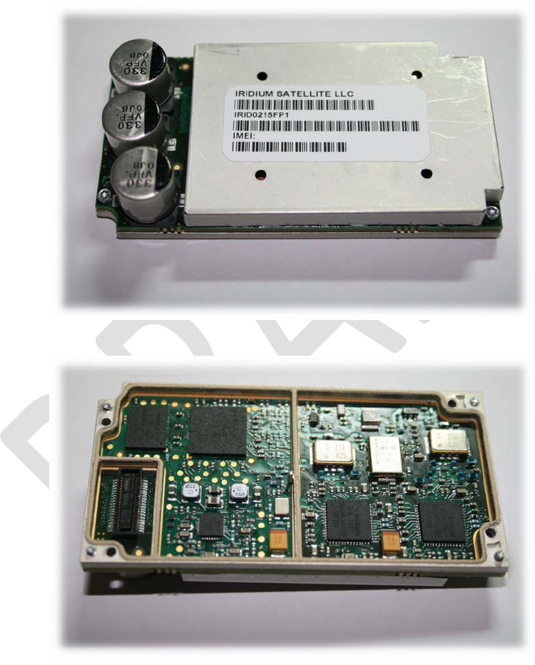
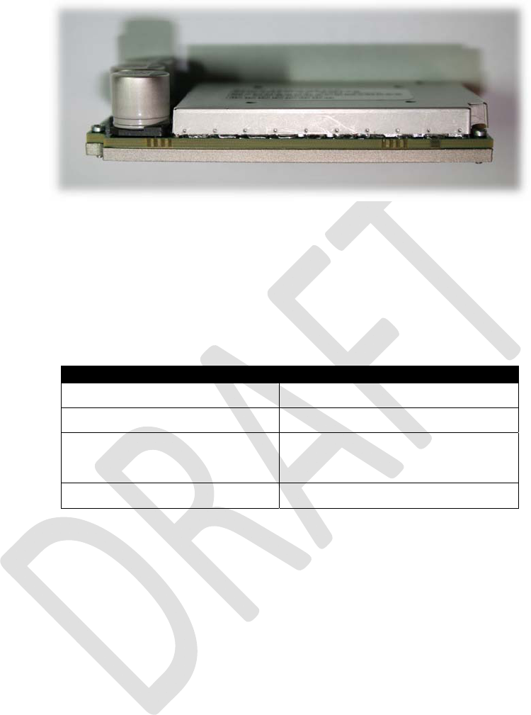
2 Physical Specification
For illustrative purposes, pictures of the Iridium 9523, fitted with its aluminum shielding frame, are shown
in Figure 1.
Figure 1: Photos of Iridium 9523
Top View
Bottom View
Iridium Communications, Inc. Information Contained in this Guide
Iridium 9523 Product Developers’ Guide is Subject to Change Without Notice
Revision 2.6
Iridium Communications, Inc. Distribution of Guide Restricted
Proprietary & Confidential Information Page 14 of 115 to Product Developers
Only
Left View
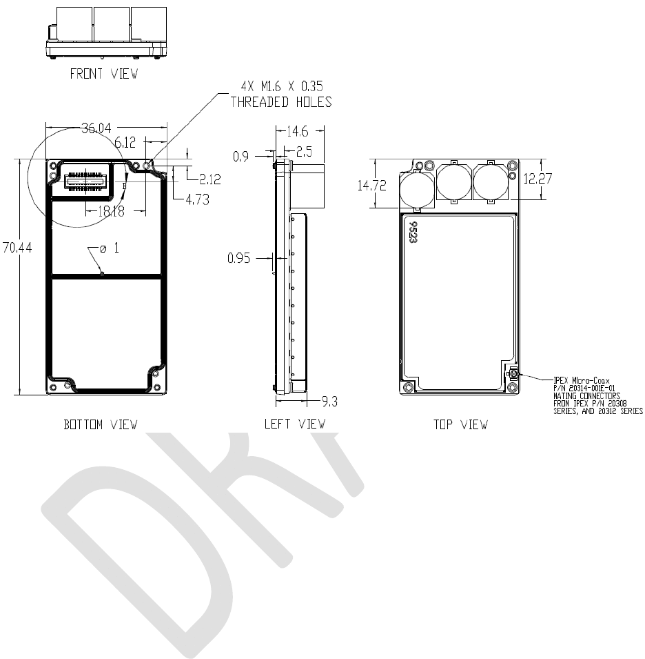
2.1 Dimensions and Layout
The overall dimensions of the Iridium 9523 and its weight are summarized in Table 2 and represented
graphically in Figure 2.
Table 2: Iridium 9523 Mechanical Dimensions
Parameter Value
Length 70.44 mm
Width 36.04 mm
Height (from FA board) 14.6 mm max (reservoir capacitors)
8.9 mm (screening can)
Weight (approximate) 32g
The Iridium 9523 consists of a single PCB with components mounted on top and bottom sides.
On the top side, there are three reservoir capacitors, the RF connector, and a screening can covering all
the remaining circuits.
The bottom side has a Molex 40-pin multi-way user interface connector. The bottom side does not have a
screening can, but instead the PCB artwork has an exposed ground ring all around the edge of the board.
This ground ring makes contact with an aluminum screening frame, attached to the Iridium 9523 by four
corner thread-forming screws. The tips of these screws protrude through the aluminum frame and act as
alignment pins when mounting onto the FA board. The aluminum frame also has at its center a 1.0mm
diameter alignment pin.
There are a further four corner screw holes through the aluminum frame and PCB for securing the 9523
to the FA board.
The two height values provided in Table 2 do not include the height of the compressible gasket on the
bottom of the 9523 that will mate to the FA board. It is assumed that this gasket will compress to near
zero thickness if screws are torqued sufficiently.
Iridium Communications, Inc. Information Contained in this Guide
Iridium 9523 Product Developers’ Guide is Subject to Change Without Notice
Revision 2.6
Iridium Communications, Inc. Distribution of Guide Restricted
Proprietary & Confidential Information Page 15 of 115 to Product Developers
Only
Figure 2: Dimensions of the Iridium 9523
(Dimensions in millimeters)
2.2 Field Application Board Mounting
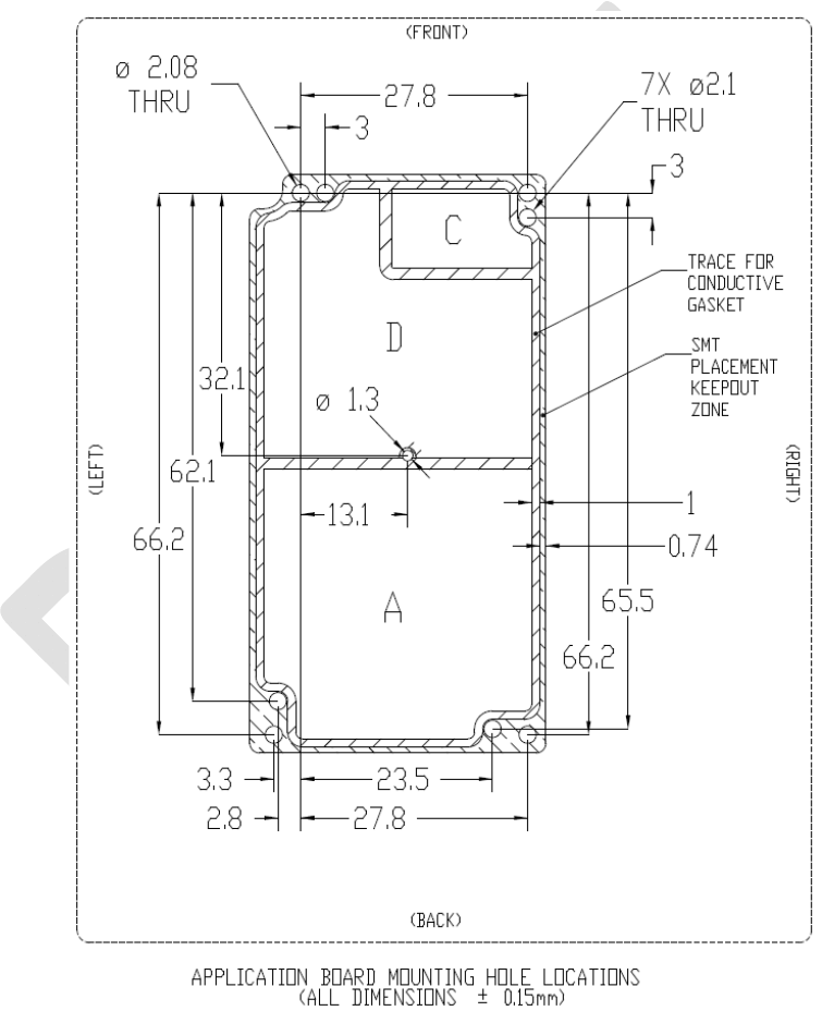
The 9523 is designed to be mounted to an FA board as illustrated in Figure 3.

Iridium Communications, Inc. Information Contained in this Guide
Iridium 9523 Product Developers’ Guide is Subject to Change Without Notice
Revision 2.6
Iridium Communications, Inc. Distribution of Guide Restricted
Proprietary & Confidential Information Page 16 of 115 to Product Developers
Only
Figure 3: Illustration of mounting module to application board
The FA board must have a socket mating to the Molex 40-pin multi-way user interface connector on the
bottom of the 9523. See section 3.1.1 for the connector part number. The Molex connectors and
aluminum frame set the separation between the Iridium 9523 and FA boards at 2.5 mm.
In order to meet type approval standards for EMC, the FA board should include a ground ring and a good
ground layer on its top surface to act as the fifth side of the screening can.
The layout of the mounting location for the 9523 on the FA board – including the locations and diameters
of all nine holes, layout of the grounding ring, and identification of areas with different grounding
requirements – is shown in Figure 4. A CAD file showing this information in DXF format can be obtained
from Iridium in order to assist layout of FA boards.
The FA board must have screw holes lining up with the 9523’s four 1.8mm corner mounting screw holes.
The 9523 must be secured to the FA board with four M1.6x0.35 screws through these holes. The FA
board must also have four corner alignment holes and one center alignment hole lining up, respectively,
with the 9523’s four 1.6mm corner protruding screws and one 1mm center alignment pin. The screw
holes should be at least 1.8mm and the alignment hole at least 1.2mm, but they may be made slightly
larger for greater tolerance. In Figure 4 below, one of the screw holes is 2.08mm, providing the primary
alignment, while the other three screw holes are 2.1mm. In the same figure, the center alignment hole is
1.3mm. These dimensions are recommendations; other dimensions may be used so long as the 9523 is
properly aligned with the user interface connector and ground trace.
In Figure 4, area ‘A’ of the FA board sits under sensitive analog circuitry on the 9523’s bottom side, and it
is essential that no components or tracks on the FA board appear in this area; it must be filled entirely
with a solid ground plane on the top layer of the FA board.
Area ‘D’ sits under digital and power circuits. Ideally, this will also be shielded with a solid ground plane.
However, it is acceptable to place tracks and low-profile components in area ‘D’, so long as care is taken
to avoid mechanical clashes and due consideration is taken of EMC issues.
Area ‘C’ contains the Molex user interface connector and should be free of surface copper.
Iridium Communications, Inc. Information Contained in this Guide
Iridium 9523 Product Developers’ Guide is Subject to Change Without Notice
Revision 2.6
Iridium Communications, Inc. Distribution of Guide Restricted
Proprietary & Confidential Information Page 17 of 115 to Product Developers
Only
The FA board must provide a sufficient margin free of conductive elements around the 9523 perimeter in
order to avoid electrical shorts with the 9523. This is indicated by the ‘SMT Placement Keepout Zone’.
Partner solutions must be provide sufficient clearance above the conductive capacitors and shield can on
the top of the 9523 to prevent an electrical short.
Figure 4: Mounting location dimensions and layout
(Dimensions in millimeters)

Iridium Communications, Inc. Information Contained in this Guide
Iridium 9523 Product Developers’ Guide is Subject to Change Without Notice
Revision 2.6
Iridium Communications, Inc. Distribution of Guide Restricted
Proprietary & Confidential Information Page 18 of 115 to Product Developers
Only
2.3 Environmental
2.3.1 Environmental Specification
The environmental specifications of the Iridium 9523 are summarized in Table 3 below.
Table 3: Environmental Specifications
Parameter Value
Operating Temperature Range -30ºC to +70ºC
Operating Humidity Range ≤ 75% RH
Storage Temperature Range -40ºC to +85ºC
Storage Humidity Range ≤ 93% RH
2.3.2 Environmental Tests Performed
It is expected, based on testing performed on a system that incorporates the Iridium 9523, that the Iridium
9523 would pass the tests listed in Table 4. A later revision of this document will specify which of these the
Iridium 9523 has been tested to in conjunction with a test interface board that offers no protection.
Table 4: Environmental Tests
Test Name Test Reference Test Description
IEC Vibration (IEC60068-2-64) Mount unit to a vibration table and excite between 15
and 500 Hz
Mil Spec 810F
Low Pressure (500.4 - II) Decrease pressure to 57.2 kPa (equivalent to 15,000 ft)
at a rate not to exceed 10 m/s and hold for 1 hour
High Temperature (501.4 - I) Over 24 hours, cycle the unit from 33ºC to 71ºC and
back to 33ºC. Repeat 7 times.
High Temperature (501.4 - II) Test is a subset of High Temperature 501.4 - Part I,
focused on the first three cycles.
Low Temperature (502.4 - I) Soak unit for 24 hours at -45ºC
Low Temperature (502.4 - II) Soak unit for 4 hours at -10ºC
Temperature Shock (503.4 - I)
Soak unit at -40C for 4 hours. Transfer to 85C chambe
r
and soak additional 4 hours. Repeat 3 times. Each
transfer from one temperature environment to the other
should be made in less than 1 minute.
Vibration (514.5 - I, Cat. 8) Secure unit to a vibration table and excite randomly
from 15-2000 Hz at 0.01 - 0.03 g^2/Hz.
Shock (516.4 - I) Expose unit to 3 shocks of 40g over approximately
11ms in each of 3 primary axes (9 total shocks).

Iridium Communications, Inc. Information Contained in this Guide
Iridium 9523 Product Developers’ Guide is Subject to Change Without Notice
Revision 2.6
Iridium Communications, Inc. Distribution of Guide Restricted
Proprietary & Confidential Information Page 19 of 115 to Product Developers
Only
3 Electrical Interfaces
The following subsections contain information for the electrical interfaces of the Iridium 9523 for the non-
RF connections. The RF interface is covered in Section 4.
3.1 User Connector
Table 5 lists the connections to the Iridium 9523 on the user connector.
Table 5: Signal Groups on User Connector
Signal group Signal function
PCM Digital Audio Two synchronous serial interfaces carrying 16-bit, 8 kHz sample rate
PCM audio data
Each port has 4 wires – data in each direction, clock and frame signals
Only one digital audio port is in use at any time
Port 1 has a secondary function during factory testing, to carry the 90ms
frame synchronization from the test equipment
DPL port Serial asynchronous control interface
2 wires – data in each direction
Data/Fax port Serial asynchronous control interface
8 wires – data in each direction plus control signals
The full set of control signals may be used for a Data/Fax port
SIM interface Standard SIM signals
5 wires – data, clock, reset, enable, voltage select
Power Battery Supply to Iridium 9523
5 power pins – 3x battery voltage and 2x boost voltage
6 grounds
1 boost regulator control line (PA_BOOST_EN)
GPIO, antenna
configuration
2 wires – ANT_DET_PWR and FULL_POWER_EN. Signals provided as
a mechanism to restrict the transmitted power – for example in order to
meet SAR standards.
Other GPIO 2 wires – TX_ACTIVE which may be used as an output to indicate when
the transmitter is active, and LBT_HSTB which determines the operating
mode of the software on the Iridium 9523.
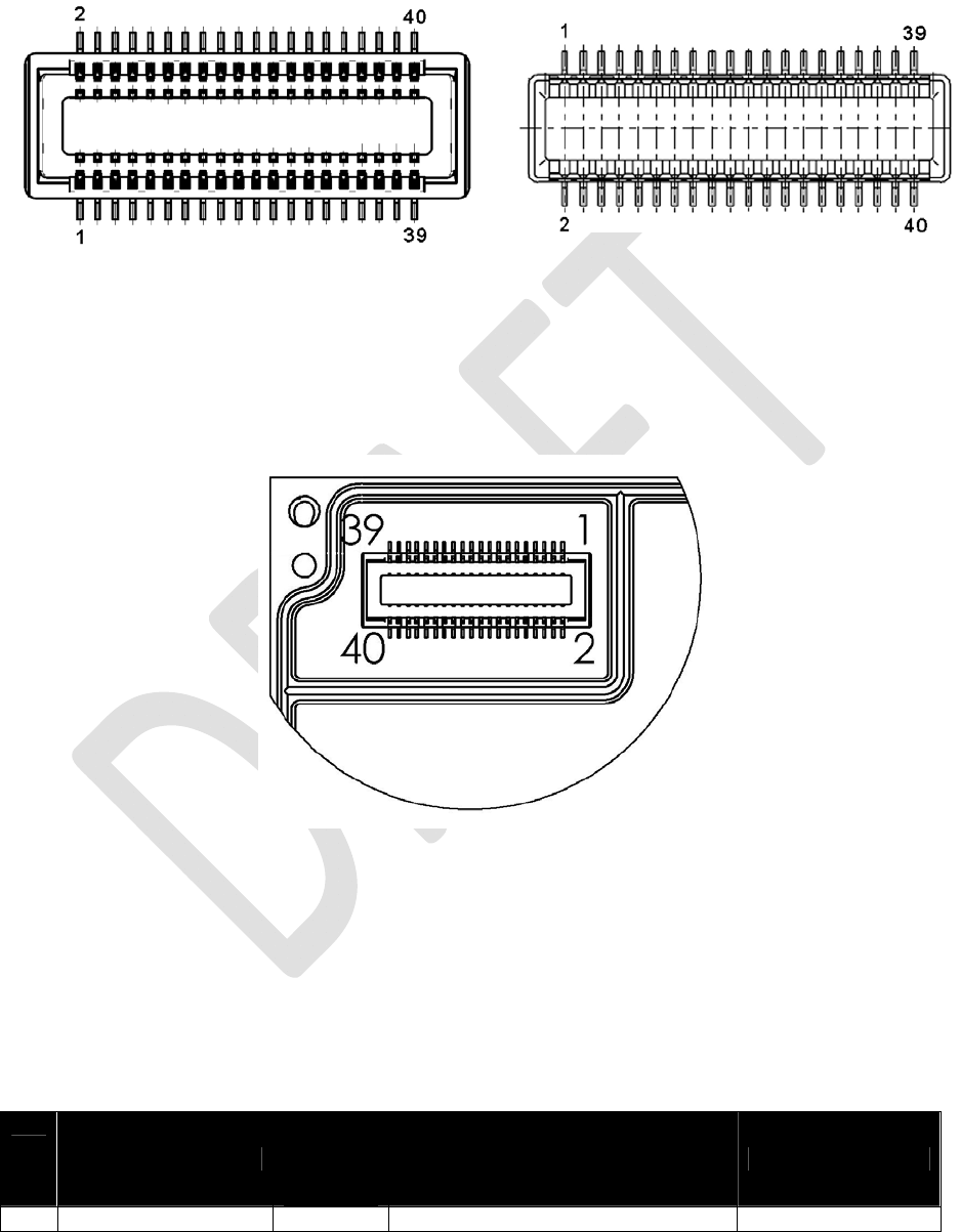
3.1.1 User Connector Type
The connector on the Iridium 9523 is a 40-way, 0.5 mm pitch Molex low-profile header connector, part
number 54102-0404.
This connector provides the ability for a stackable board-to-board configuration, allowing connection to
the host system motherboard via a mating 53885-0408 socket.
Data sheets on these connectors can be found at: http://www.molex.com
Pin numbering schemes for the Molex connectors on the Iridium 9523 and the host FA board are shown
in Figure 5 (both pictures show the pin-out when looking down onto the boards).
Iridium Communications, Inc. Information Contained in this Guide
Iridium 9523 Product Developers’ Guide is Subject to Change Without Notice
Revision 2.6
Iridium Communications, Inc. Distribution of Guide Restricted
Proprietary & Confidential Information Page 20 of 115 to Product Developers
Only
Figure 5: Pin numbering scheme for User Connector
Molex 54102-0404 on Iridium 9523: Molex 53885-0408 on FA PCB:
Error! Reference source not found. provides a reference for the pin designation and shows the connector’s
location and rotation with respect to the corner of the Iridium 9523 board. This view is for illustrative
purposes only. This view designation is when looking into the user connector towards the Iridium 9523.
Figure 6: User Connector Pin Number Designation
3.1.2 User Connector Pin Allocation
The user connector is a 2-row 40-way header. Individual pin assignments are shown in Table 6 and the
limits for the digital signals are listed in Table 7. Multiple supply grounds are provided and all supply rails
and supply grounds are required to be connected to the power supply in order to limit the current on any
one pin.
Table 6: User Connector Pin Allocation
Pin
No. Signal Name
Signal
direction
(WRT
modem)
Signal function Signal group
1 CODEC_PCMCLK Out Clock PCM audio port 1

Iridium Communications, Inc. Information Contained in this Guide
Iridium 9523 Product Developers’ Guide is Subject to Change Without Notice
Revision 2.6
Iridium Communications, Inc. Distribution of Guide Restricted
Proprietary & Confidential Information Page 21 of 115 to Product Developers
Only
Pin
No. Signal Name
Signal
direction
(WRT
modem)
Signal function Signal group
2 CODEC_PCMIN Out Data from modem PCM audio port 1
3 CODEC_PCMSYNC Out Frame Sync PCM audio port 1
4 CODEC_PCMOUT In Data to modem PCM audio port 1
5 0V Ground Power supply
6 0V Ground Power supply
7 UC_DACLK Out Clock PCM audio port 2
8 UC_DATX Out Data from modem PCM audio port 2
9 UC_DAFS Out Frame Sync PCM audio port 2
10 UC_DARX In Data to modem PCM audio port 2
11 0V Ground Power supply
12 0V Ground Power supply
13 DPL_RXD In Data to modem DPL port
14 DPL_TXD Out Data from modem DPL port
15 DF_RX Out Data from modem Data/Fax port
16 DF_TX In Data to modem Data/Fax port
17 DF_CTS Out Clear to Send Data/Fax port
18 DF_DCD Out Carrier Detect Data/Fax port
19 DF_DSR Out Data Set Ready Data/Fax port
20 DF_RI Out Ringing Indication Data/Fax port
21 DF_RTS In Request to Send Data/Fax port
22 DF_DTR In Data Terminal Ready Data/Fax port
23 SIM_1V8_3V Out Voltage select SIM
24 SIM_CLOCK Out Clock SIM
25 SIM_ENABLE Out Enable SIM
26 SIM_RESET Out Reset SIM
27 SIM_DATA_IO Bidir Data SIM
28 FULL_POWER_EN In Enable full RF power GPIO
29 ANT_DET_PWR Out Power for docking cradle detector GPIO
30 LBT_HSTB In Handset/LBT switch GPIO
31 TX_ACTIVE Out Signal to mute GPS receiver GPIO
32 TRX_ON In Enable modem power regulators Power supply
33 PA_BOOST_EN Out Enable boost converter Power supply
34 0V Ground Power supply
35 0V Ground Power supply
36 VBAT In Battery Voltage Power supply
37 VBOOST In Boost Voltage for PA Power supply
38 VBAT In Battery Voltage Power supply
39 VBOOST In Boost Voltage for PA Power supply
40 VBAT In Battery Voltage Power supply
Table 7: Limits for 3.3V Digital Signals
Parameter Symbol Min Max Unit
Input High Voltage VIH 2.0 5.5 V
Input Low Voltage VIL -0.3 0.8 V
Input current IIN 20 µA
Input capacitance CIN 10 pF
Output High Voltage VOH 2.4 V

Iridium Communications, Inc. Information Contained in this Guide
Iridium 9523 Product Developers’ Guide is Subject to Change Without Notice
Revision 2.6
Iridium Communications, Inc. Distribution of Guide Restricted
Proprietary & Confidential Information Page 22 of 115 to Product Developers
Only
Output Low Voltage VOL 0.4 V
Low Level Output Current IOL 4.4 mA
High Level Output Current IOH 5.5 mA
3.2 DC Power Supply Interface
3.2.1 Battery Power Input, VBAT
VBAT is the input from a Lithium-ion battery or other low-voltage source via the user connector. It must be
in the range 3.2 to 6V and capable of supplying a maximum current of 500mA.
3.2.2 Boost Power Input, VBOOST
VBOOST - Boost converter input via user connector. See Section 3.2.4 for details.
The Iridium 9523 produces the logic signal PA_BOOST_EN to indicate when the external Boost Power
voltage must be applied. This signal can be used as the enable signal to an external boost regulator (logic
high = VBOOST needed, logic low = VBOOST not needed).
3.2.3 Power On/Off Control, TRX_ON
The input signal TRX_ON is provided to allow the Iridium 9523 to be powered off. This signal controls the
power regulators on the Iridium 9523.
The Iridium 9523 starts up when power is applied and the TRX_ON input is high. As long as the input
voltage is applied, logic high on this line turns the Iridium 9523 on and a logic low turns it off. If this line is
not required then it must be connected directly to the VBAT supply.
Prior to turning off the modem a “flush memory” (AT*F) command should be issued to ensure all memory
write activity is completed.
When an Iridium 9523 is powered off, the power-on-reset circuit requires 2 seconds for voltages to decay.
Product Developers should therefore not reapply power until this time has elapsed after power has
reached 0V. If the 2 second wait time is not adhered to, the reset circuit may not operate and the modem
could be placed in a non-operational state. The state is not permanent and can be rectified by the above
procedure.
Damage may be caused if TRX_ON is high and VBAT is not supplied. Partners must ensure that this
condition cannot occur either by generating TRX_ON from VBAT or by adding protection circuitry such as
a clamp diode between TRX_ON and VBAT.
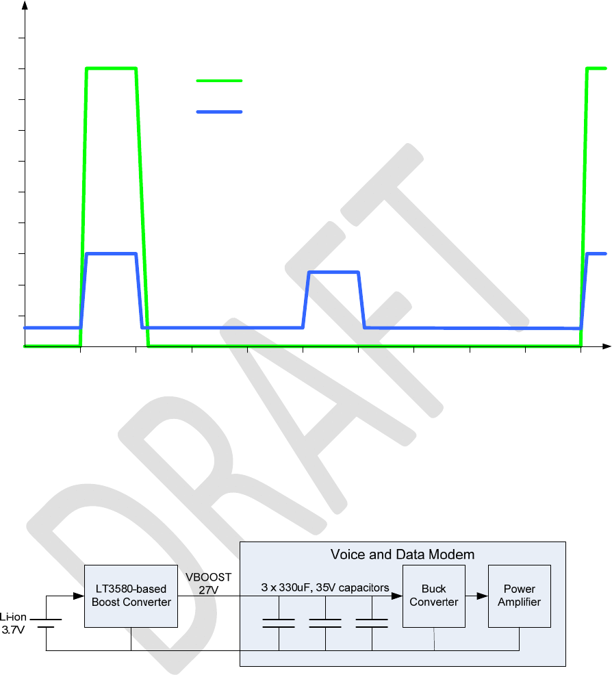
3.2.4 Typical Power Usage Profile
The amount of current taken by the Iridium 9523 on its two supply rails depends on whether it is active in
a call and the ‘power step’ level that the transmitter is using. The current consumption during a call at the
highest power step is shown in Figure 7.
Iridium Communications, Inc. Information Contained in this Guide
Iridium 9523 Product Developers’ Guide is Subject to Change Without Notice
Revision 2.6
Iridium Communications, Inc. Distribution of Guide Restricted
Proprietary & Confidential Information Page 23 of 115 to Product Developers
Only
Figure 7: Current Profile of Supply Rails
I/mA
100
200
300
400
500
600
700
800
900
1000
10 20 30 40 50 60 70 80 90 100 t/ms
Current in VBOOST Rail
Current in VBAT Rail
The current peak in the VBOOST rail lasts for 8.3ms and repeats every 90ms (this is the period of a frame
in the Iridium air interface). When not transmitting, the VBOOST current returns to zero. The VBOOST
current was measured when the Iridium 9523 was connected to a 27V power source that could meet its
instantaneous power requirements (around 25W).
A block diagram of the VBOOST power supply in a typical Lithium-ion powered application is shown in
Figure 8.
Figure 8: VBOOST block diagram
Iridium’s products use a boost-converter circuit based on the Linear Technology LT3580 to produce the
VBOOST rail. This circuit is not capable of supplying the instantaneous current needed by the power
amplifier. The Iridium 9523 therefore includes a total capacitance of 1000μF on the VBOOST rail to store
charge; these capacitors are depleted during the transmit time-slot (8.3ms) and replenished during the
remainder of the frame time (81.7ms). The voltage across the capacitors at the end of each transmit time-
slot must not fall below 10.5V; otherwise the output voltage of the buck converter will drop too low and
affect the transmitted waveform from the PA. The average current taken from the boost converter in this
configuration is around 300mA.

Iridium Communications, Inc. Information Contained in this Guide
Iridium 9523 Product Developers’ Guide is Subject to Change Without Notice
Revision 2.6
Iridium Communications, Inc. Distribution of Guide Restricted
Proprietary & Confidential Information Page 24 of 115 to Product Developers
Only
It is possible to produce VBOOST in other ways, particularly if the FA has a convenient supply rail that
has high enough voltage and current capacity. Table 8 shows the permissible limits for any VBOOST
supply.
Table 8: VBOOST Specification
Parameter Value
Absolute maximum voltage
(limited by capacitor rating) 35V
Maximum recommended voltage 32V
Minimum voltage when capacitors are charged 27V
Minimum voltage when enabled
(limited by minimum input to buck converter to produce PA power rail) 10.5V
Maximum current into VBOOST pins
(limited by rating of inter-board connector) 1A
Maximum power taken by buck converter
(during transmit time-slot) 30W
The maximum average power requirement over a 90ms period is 3.1W. The capacitors discharge to
typically 15V during the transmit burst when operating at maximum power. A typical design would have a
power limit of between 5 and 6 Watts (current approximately 0.25 Amp) so that the reservoir capacitors
are replenished in approximately half the allowed time.
If the boost voltage at the start of the transmit burst is below the minimum (27V) then the capacitors may
discharge to below 9.5V, in which case the transmitter power will reduce.
There is a residual VBAT current of about 70mA all the time that the Iridium 9523 is switched on, even
when not in a call. Periodically, the Iridium 9523 will draw about 250mA from the VBAT rail for about
20ms, as it maintains synchronization with the signal from the satellites.
When an Iridium call is in progress, there are two peaks in the current drawn by the VBAT rail in each
90ms frame – one of about 300mA during the transmit time-slot and a slightly smaller one, 250mA, during
the receive time-slot.
At the start of each of period when the receiver or transmitter is active a burst of current will be drawn, as
the radio circuitry switches on. This current is caused by the charging of six 4.7μF capacitors on the
outputs of internal voltage regulators.
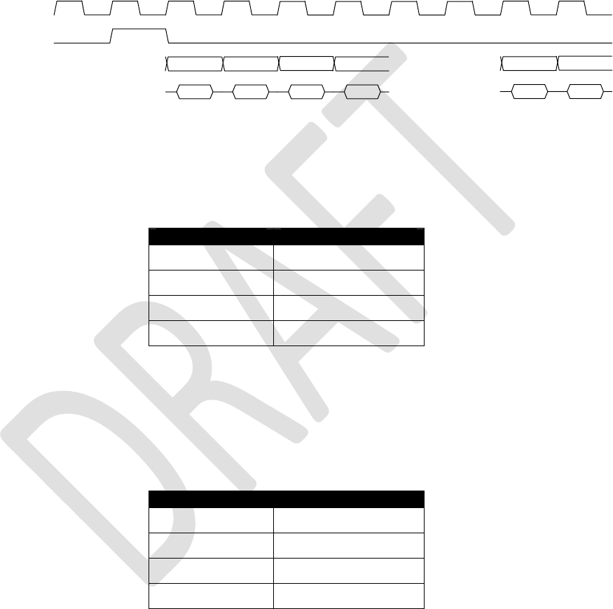
3.3 PCM Digital Audio
The Iridium 9523 has two 15-bit linear PCM digital audio ports, though only one of these can be in use at
any time. The active port is selected using the AT+CAR command. This setup allows the FA board to
provide two parallel audio paths and switch between them through software instead of hardware. The two
ports have identical signals and timing, as shown in Figure 9. The PCM clock and sync signals are
outputs from the Iridium 9523.
The PCM clock signal has a frequency of 2048 kHz with an accuracy of 1 ppm, but it is derived from an
internal clock source by a fractional divider so each clock high period and low period is either 238.1 ns or
297.6 ns.
The PCM clock, sync and data signal outputs are all timed from the same internal clock and are skewed
by less than 1 ns (at equal load).
Iridium Communications, Inc. Information Contained in this Guide
Iridium 9523 Product Developers’ Guide is Subject to Change Without Notice
Revision 2.6
Iridium Communications, Inc. Distribution of Guide Restricted
Proprietary & Confidential Information Page 25 of 115 to Product Developers
Only
The PCM data input has set-up and hold time requirements of 30 ns with respect to the falling edge of the
PCM clock signal.
The two PCM ports were originally intended to be connected to a voice source/sink via a codec (such as
the Texas Instruments TLV320AIC1110) for analog audio and directly for digital audio, but there is no
need to use them in this way.
Figure 9 - PCM waveform diagram
3.3.1 Port 1
Port 1 has the following signal pins:
Table 9: PCM Port 1 Signals
Signal function Signal name
PCM clock output CODEC_PCMCLK
PCM sync output CODEC_PCMSYNC
PCM data output CODEC_PCMIN
PCM data input CODEC_PCMOUT
Note: the data signal names on Port 1 are defined from the point of view of an externally connected
codec.
3.3.2 Port 2
Port 2 has the following signal pins:
Table 10: PCM Port 2 Signals
Signal function Signal name
PCM clock output UC_DACLK
PCM sync output UC_DAFS
PCM data output UC_DATX
PCM data input UC_DARX
Note: the data signal names on Port 2 are defined from the point of view of the Iridium 9523.
3.3.3 11Hz Signal for Manufacturing and Regulatory Testing
An external ‘frame tick’ signal needs to be passed to the Iridium 9523 during regulatory radio testing of
the host system, and possibly also during manufacturing testing. This frame signal has a period of 90ms
(11.1Hz) and is fed to the Iridium 9523 using the CODEC_PCMOUT PCM data input.
PCM clock
PCM sync
PCM output
PCM input
1 (msb) 23 15 16 (lsb)
1 (msb) 23 15 16 (lsb)
4
4

Iridium Communications, Inc. Information Contained in this Guide
Iridium 9523 Product Developers’ Guide is Subject to Change Without Notice
Revision 2.6
Iridium Communications, Inc. Distribution of Guide Restricted
Proprietary & Confidential Information Page 26 of 115 to Product Developers
Only
The frame tick signal can have any mark:space ratio but must be externally synchronized to the Iridium
9523’s internal clock. This is most easily achieved by double buffering the signal through two D-type
latches clocked by CODEC_PCMCLK.
3.4 DPL port
The DPL port is a three-wire asynchronous serial port. It carries 8-bit, no parity data at 115,200 baud.
The DPL port enables peripherals such as handsets and SIM card readers to be interfaced to the Iridium
9523. The interface utilizes an Iridium proprietary communication bus not detailed in this document.
Details can be made available after appropriate Non-Disclosure and/or License Agreements are
executed.
The serial data signals use standard 3.3V signals with conventional polarity. If desired, an external RS232
level converter could be fitted to the FA board to extend range.
3.5 Data/Fax port
The asynchronous serial data/fax interface is comprised of eight standard RS232 data (8-bit, no parity),
control, and status signals plus a ground level signal reference. This interface allows the FA to utilize the
Iridium 9523’s modem functionality via AT command control. With respect to this interface, the Iridium
9523 behaves as a DCE (Data Communication Equipment), and the FA behaves as a DTE (Data
Terminal Equipment).
A 3-wire RS232 Data minimal interface may also be implemented; however the 9-wire interface offers
better control and is the recommended implementation.
Autobaud is enabled by default. Autobaud will occur on the following characters: ‘a’, ‘A’, or CR (carriage
return). Autobaud will also occur on the escape sequence character, provided this is an odd number
character. Normally this is set to ‘+’ in register S2. See the AT Command Reference for details.
3.5.1 9-Wire and 3-Wire Operation
By default, the serial interface operates as a 9-wire connection. Table 11 describes each of the signals,
where “input” means an input to the Iridium 9523, and vice-versa for “output”.
Table 11: Data/Fax Port Serial Interface Signals
Signal Description
RX Active high data output [The FA receives the data from the Iridium 9523]
TX Active high data input [Data is transmitted from the FA to the Iridium 9523]
GND 0V
RTS Active low flow control input
CTS
Active low flow control output
RTS and CTS are used together to implement hardware flow control when enabled with
AT&K3, refer to section 5.7.13
DTR Active low handshaking input
AT&Dn controls how the Iridium 9523 uses DTR, refer to section 5.7.11
DSR
Active low handshaking output
The Iridium 9523 drives DSR ON
The FA may use this signal as an indication that the Iridium 9523 is powered up and
ready to receive AT commands

Iridium Communications, Inc. Information Contained in this Guide
Iridium 9523 Product Developers’ Guide is Subject to Change Without Notice
Revision 2.6
Iridium Communications, Inc. Distribution of Guide Restricted
Proprietary & Confidential Information Page 27 of 115 to Product Developers
Only
Signal Description
RI
Active low ring indicator output
The Iridium 9523 drives RI ON when it receives an Automatic Notification from the
network that a Mobile Terminated SBD Message is queued at the Gateway, and drives
RI OFF after 5 seconds or when the FA initiates an SBD session, whichever occurs first
DCD Active low handshaking output
The Iridium 9523 drives DCD ON to indicate that the Iridium link is active
Note that the Ring Indicator (RI) pin is used by the Iridium 9523 to indicate that a Mobile Terminated SBD
(MT-SBD) message is queued at the Gateway. The Field Application can monitor this pin and use
appropriate AT Commands to command the Transceiver to retrieve the MT-SBD message.
The serial interface may be operated with a 3-wire connection, where only transmit, receive and ground
signals are used. The Voice and Data Modem supports XON/XOFF flow control, which can be enabled
using the AT&Kn command, but the amount of buffering is restricted by its limited buffer space and
processing resources. There is therefore a risk of over-run and data loss, especially at high baud rates,
so the use of a 9-wire interface is recommended whenever possible.
When operating with a 3-wire connection, the following rules apply:
AT&Dn must be set to AT&D0 to ignore the DTR input
AT&Kn must be set to AT&K0 to disable RTS/CTS flow control
The other output signals may be connected, and operate as follows:
o CTS driven ON (low)
o DSR operates as normal
o RI operates as normal
o DCD operates as normal
Notes:
1. RTS/CTS flow control, when enabled, is only used when the data port is in data mode. In AT command
mode, RTS is ignored and CTS is driven ON (low).
2. If the DC input to the modem is to be disconnected, the developer will need to “tri-state” the serial
interface to prevent a possible latch-up condition.
3.5.2 Configuration Settings
The Iridium 9523 allows the FA to configure the data port communication parameters. The three
configuration types are active, factory default, and stored. The active configuration is the set of
parameters currently in use. They can be changed by the FA individually via specific AT commands. The
factory default configuration is stored in permanent memory. This configuration can be recalled at any
time through use of the AT&Fn command.
Two groups of settings, or “profiles”, can be stored as user-defined configurations. The FA first creates
desired active configurations and then writes them to memory using the AT&Wn command. These
profiles can be designated to be loaded as the active configuration upon Iridium 9523 power-up through
use of the AT&Yn command. The Iridium 9523 can be reset without loss of power to these profiles
through use of the ATZn command.
The configuration settings are stored in “S-register” locations and are detailed further in Section 6.

Iridium Communications, Inc. Information Contained in this Guide
Iridium 9523 Product Developers’ Guide is Subject to Change Without Notice
Revision 2.6
Iridium Communications, Inc. Distribution of Guide Restricted
Proprietary & Confidential Information Page 28 of 115 to Product Developers
Only
3.5.3 Modes of Operation
The serial interface is always in one of three modes: command mode, SBD data mode or SBD session
mode. When the data port is in command mode, AT commands can be entered to control the Iridium
9523. In command mode, flow control has no effect, with the RTS input ignored and the CTS output
driven ON (low). When in SBD data mode, the Iridium 9523 is transferring binary or text SBD message
data to or from the FA.
In SBD data mode:
All characters from the FA not forming part of the message data are ignored (i.e. no AT
commands may be entered)
No unsolicited result codes are issued
RTS/CTS flow control, if enabled, is active. When RTS is OFF (high), the Iridium 9523
suspends transfer of data to the FA; when CTS is OFF (high), the Iridium 9523 expects the FA to
suspend transfer of data.
When in SBD session mode, the Iridium 9523 is attempting to conduct an SBD session with the network.
In SBD session mode:
The FA must wait for the +SBDI [X][A]session result code
All characters from the FA are ignored
Unsolicited result codes are issued where those codes have been enabled
Transitions between the modes of operation are performed automatically by the Iridium 9523 in response
to the SBD AT Commands; the FA has no other control over the mode.
3.5.4 Serial port signal levels
The inputs on the Iridium 9523 Data/Fax serial port (RTS, DTR and TXD) will operate correctly at 3.3V
digital signal levels.
The five outputs from the Iridium 9523 Data/Fax serial port (DCD, DSR, CTS, RI and RXD) are all at 3.3V
digital levels.
RS-232 interface chips can be fitted to the FA board if connection to an external RS232 link is required.
3.6 SIM interface
The Iridium 9523 needs an external Iridium SIM card and socket to be connected to its SIM interface. The
signals operate at 3.3V logic levels, so an external SIM level converter such as the ONSemi NCN4555
must be connected between the Iridium 9523 and the SIM connector/socket to allow 3V or 1.8V SIM
cards to be used.
An external SIM card reader may also be interfaced as a peripheral to the Iridium 9523 via the DPL
interface. A SIM card in the external reader will take precedence over the SIM chip connected to the SIM
interface when both are present.
3.7 GPIO Signals
There are four GPIO signals to the Iridium 9523, as described in this section.

Iridium Communications, Inc. Information Contained in this Guide
Iridium 9523 Product Developers’ Guide is Subject to Change Without Notice
Revision 2.6
Iridium Communications, Inc. Distribution of Guide Restricted
Proprietary & Confidential Information Page 29 of 115 to Product Developers
Only
3.7.1 Transmit power Control
The radiated power output from the Iridium transmitter can exceed SAR safety limits if the antenna is too
close to the operator’s body. An Iridium handset has a telescopic antenna to provide the necessary safe
distance. The GPIO signals ANT_DET_PWR and FULL_POWER_EN are used to control the transmit
power in conjunction with an antenna position-detector switch.
The Iridium 9523 polls the position-detector switch by providing a 3.3V output on ANT_DET_PWR in
order to provide power to the antenna position sensing circuitry. When ANT_DET_PWR is high, the
position sensing circuit must take FULL_POWER_EN high to enable full transmit power.
3.7.2 External GPS Receiver Switch
If the Iridium 9523 is used near a GPS receiver, it is possible that the input circuitry of the GPS receiver
could be damaged by the output power of the Iridium transmitter, especially if the two devices share a
single antenna. The Iridium 9523 has a GPIO signal, TX_ACTIVE, which is high whenever the Iridium
transmitter is active and this could be used to control a switch on the input of the GPS receiver.
The TX_ACTIVE signal goes high 610us before the start of a transmit burst (ie. full power), and goes low
220us after the end of the burst. There is also 100us of power ramp-up before the burst and 100us of
ramp-down after the burst.
3.7.3 Modem/Handset Mode Select Signal
A further GPIO signal, LBT_HSTB, is used to indicate whether the Iridium 9523 should operate as though
it is mounted in a handset or a modem device. It should be pulled to 3.3V for normal modem operation, or
0V for handset mode. The major differences are:
Data/Fax port is operational in modem mode and disabled in handset mode
Background radio scanning for active radio channels is less intensive in handset mode, because
power consumption is a more important issue for a battery-powered handset.

Iridium Communications, Inc. Information Contained in this Guide
Iridium 9523 Product Developers’ Guide is Subject to Change Without Notice
Revision 2.6
Iridium Communications, Inc. Distribution of Guide Restricted
Proprietary & Confidential Information Page 30 of 115 to Product Developers
Only
4 RF Interface
This section describes the physical characteristics of the RF connector and specifications of the RF
Interface.
4.1 RF Connector Type
The RF connector on the Iridium 9523 is an I-PEX part number 20314-001E-01, from their MHF product
range. When mating to the Iridium 9523 RF connector, use a suitable plug from the MHF (20308) or
MHFII (20312) ranges.
Additional information can be found at: http://www.i-pex.com
Note that the RF connector on the Iridium 9523 is not mounted directly to the FA board along with the
user interface connector. It must be attached to the FA board through a coaxial cable.
Note that for safety reasons, the RF connector on the Iridium 9523 should not be directly connected to an
external antenna cable or cable distribution system. Paragraph 7.3 of EN60950-1:2006 safety standard
requires that users are protected against high voltages that might appear on these cables. This can be
achieved either by inserting a high-voltage isolating capacitor in series with the signal or by grounding the
shield of the coaxial cable. The I-PEX connector has limited voltage capacity; therefore protection needs
to be provided on the FA board. Developers are encouraged to review the EN60950-1:2006 standard for
additional details.
4.1.1 Antenna Characteristics
The Iridium 9523 should be connected to a certified Iridium-band antenna with the following antenna
connector characteristics as described in Table 12.
Table 12: Antenna Characteristics
Parameter Value
Impedance 50 Ohms nominal
Gain (maximum) 3 dBi
Polarization RHCP
VSWR (maximum operational) 1.5 : 1
Existing qualified Iridium antennas may be used. (i.e. antennas designed and certified for the 9601, 9602,
9522, 9522A and 9522B) in conjunction with suitable protection circuitry.
4.2 RF Interface Specifications
The RF interface requirements for the Iridium 9523 are summarized in Table 13 below.
Table 13: General RF Parameters
Parameter Value
Frequency Range 1616 MHz to 1626.5 MHz
Duplexing Method TDD (Time Domain Duplex)
Input/Output Impedance 50Ω
Multiplexing Method TDMA/FDMA

Iridium Communications, Inc. Information Contained in this Guide
Iridium 9523 Product Developers’ Guide is Subject to Change Without Notice
Revision 2.6
Iridium Communications, Inc. Distribution of Guide Restricted
Proprietary & Confidential Information Page 31 of 115 to Product Developers
Only
4.3 Radio Characteristics
Table 14 contains radio characteristics of the Iridium 9523.
Table 14: Radio Characteristics
Parameter Value
Average Power during a transmit slot (max) 7 W
Average Power during a frame (typical) 0.6 W
Receiver sensitivity (Typical level at connector) -118 dBm
Max Cable loss permitted (Note 1) 3 dB
Link Margin – Downlink (Note 2) 12 dB
Link Margin – Uplink (Note 2) 12 dB
Note 1: Cable losses should be minimized. The total implementation loss for an antenna, connectors,
cable, lightning arrestor and any other RF component between the Iridium 9523 and the antenna should
not exceed 3 dB. Implementation loss higher than this will affect the Iridium link performance and quality
of service. Solutions with a loss higher than 3 dB will not meet the requirements of Iridium Solution
Certification.
Note 2: Link Margins are given assuming a free-space propagation model.
4.4 S-meter Performance
The numbers reported over the AT command interface indicate the signal strength of the ring channel.
Care should be taken when using the S-meter readings for comparisons between devices. Of particular
note are the following:
1. There is a 0.5 dB tolerance on calibrating the S-meter.
2. Each bar represents a 2 dB increment.
3. Multiple ring channels can be present at the same time so units can lock to different signals.
4. If the reading is near the decision threshold it would be easy to see a 1 bar difference.

Iridium Communications, Inc. Information Contained in this Guide
Iridium 9523 Product Developers’ Guide is Subject to Change Without Notice
Revision 2.6
Iridium Communications, Inc. Distribution of Guide Restricted
Proprietary & Confidential Information Page 32 of 115 to Product Developers
Only
5 AT Interface
5.1 Command Types
The Iridium 9523 employs two principal types of AT commands: basic and extended. The two types have
differing syntax used to query and adjust their settings. They also have unique reference standards.
A specific basic AT command is used to reference S-registers and query and adjust their settings. Its
syntax is similar to that of extended AT commands.
5.2 Basic Commands
Basic commands are industry standard and originally developed for Hayes-compatible PSTN modems. In
many cases, basic commands consist of a single ASCII alpha character.
In other cases, a special character precedes the alpha character. Prefix characters used in Iridium 9523
basic commands include &, \, %, and *.
Most alpha characters in basic commands are followed by a numeric parameter, n. To adjust its setting,
a basic command is entered with the appropriate numeric value of n. Note that if the numeric parameter
n is omitted from the basic command entry, a value of zero is assumed for n. For example, ATXn is set to
a value of 4 by entering ATX4, whereas it is set to value of 0 by entering either ATX0 or ATX.
To query a basic command setting, the AT&V command is entered to view the active configuration of a
group of basic commands.
Some basic commands listed in this document are marked with “No action, compatibility only”. In these
cases, the basic command is accepted in the same fashion as is with other modems, but has no effect on
the operation of the Iridium 9523, since it has no meaning in the IridiumTM/SM environment.
5.3 Extended Commands
Extended commands perform actions or set parameters that extend the capability of the Iridium 9523
beyond that which is allowed by basic commands. In some cases, they were designed for non-PSTN
networks, such as the GSM network.
Most extended commands include a prefix of + followed by a single alpha character. Prefixes used in
Iridium 9523 extended commands include +C, +D, +G, +I, and +S. Extended commands designed
specifically for Iridium products include a –MS prefix.
Most extended commands include three alpha characters after the prefix, but some commands include
just one or two alpha characters after the prefix.
Some extended commands have a single execution mode. No further syntax is added after the prefix
and body of the command. For example, AT+GSN is entered as shown to query the Iridium 9523 for its
assigned serial number (i.e. IMEI).
Some extended commands incorporate a test mode to query their range of valid responses. For
example, AT+CBC is entered as shown in execution mode to query the Iridium 9523 for its battery
connection and charge status. The command is entered as AT+CBC=? in test mode to query its range of
valid responses.

Iridium Communications, Inc. Information Contained in this Guide
Iridium 9523 Product Developers’ Guide is Subject to Change Without Notice
Revision 2.6
Iridium Communications, Inc. Distribution of Guide Restricted
Proprietary & Confidential Information Page 33 of 115 to Product Developers
Only
Some extended commands incorporate set, read, and test modes. For example, AT–MSVTR is entered
as AT–MSVTR=n in set mode to enable/disable receipt of DTMF messages. It is entered as AT–
MSVTR? in read mode to query its current setting and is entered as AT–MSVTR=? in test mode to query
its range of valid settings.
Extended commands are grouped as shown below.
Extended Cellular Commands:
+C prefix
Used for GSM cellular phone-like functions
Standards: ETSI specifications GSM 07.07 [2] and GSM 07.05 [3]
Extended Data Compression Commands:
+D prefix
Used for data compression
Standard: V.25ter [1]
Extended Generic Commands:
+G prefix
Used for generic DCE issues such as identities and capabilities
Standard: V.25ter [1]
Extended Interface Control Commands:
+I prefix
Used to control the FA interface
Standard: V.25ter [1]
Extended Short Burst Data Commands:
+S prefix
Used for Short Burst Data messaging
Iridium Satellite Product Proprietary Commands:
–MS prefix
Proprietary to the Iridium product line
5.4 Command and Response Characters
The execution of a command string follows a left-to-right execution of each command followed by the
reporting of a result code for the entire string.
The ASCII character set (CCITT T.50 International Alphabet 5, American Standard Code for Information
Interchange) is used for the issuance of commands and responses. Only the low-order 7 bits of each
character are used for commands or parameters; the high-order bit is ignored. Upper case characters are
equivalent to lower case characters.

Iridium Communications, Inc. Information Contained in this Guide
Iridium 9523 Product Developers’ Guide is Subject to Change Without Notice
Revision 2.6
Iridium Communications, Inc. Distribution of Guide Restricted
Proprietary & Confidential Information Page 34 of 115 to Product Developers
Only
5.5 Command Entry
An AT command is a string of characters sent by the FA to the Iridium 9523 while it is in command mode.
A command string has a prefix, a body, and a terminator. The prefix consists of the ASCII characters AT
or at. The body is a string of commands restricted to printable ASCII characters. The default terminator
is the <CR> character.
AT command entry syntax is critical, and the following rules apply:
All commands (apart from A/ and +++) begin with a prefix of AT or at.
The commands in a command string (apart from A/ and +++) are executed only after the return or
enter key is pressed.
Use of upper or lower case letters is allowed, but not a combination of both.
The maximum number of characters in a command string is 128.
If the numeric parameter n is omitted from the basic command entry, a value of zero is assumed
for n.
If an optional parameter is omitted from an extended command, the current value is implied.
Optional parameters are enclosed by square brackets ([...]) in this document.
Spaces entered into a command string for clarity between the AT prefix and the body of the
command are ignored. Likewise, spaces entered for clarity within the command body between
alpha characters and decimal parameters are ignored.
The backspace or delete keys can typically be used to edit commands.
Characters that precede the AT prefix are ignored.
Ctrl-x can be used to abort a command line input.
Consider the following six commands to be entered in a single command line:
ATX0 (set basic command ATXn to n=0)
AT&V (execute basic command AT&V)
AT+GSN (execute extended command AT+GSN)
AT+CMEE=? (query the valid range of responses of extended command AT+CMEE)
AT+CPBR=1,12 (execute extended command AT+CPBR with parameters 1 and 12)
AT–MSVTR? (query the current setting of extended command AT–MSVTR)
The following are valid single command line entries of above six commands:
at x 0 &v +gsn +cmee=? +cpbr=1,12 -msvtr? (all lower case)
AT X 0 &V +GSN +CMEE=? +CPBR=1,12 –MSVTR? (all upper case)

Iridium Communications, Inc. Information Contained in this Guide
Iridium 9523 Product Developers’ Guide is Subject to Change Without Notice
Revision 2.6
Iridium Communications, Inc. Distribution of Guide Restricted
Proprietary & Confidential Information Page 35 of 115 to Product Developers
Only
ATX 0 &V +GSN +CMEE=? +CPBR=1,12 –MSVTR? (space omitted between AT and X)
ATX0 &V +GSN +CMEE=? +CPBR=1,12 –MSVTR? (space omitted between ATX and 0)
ATX &V +GSN +CMEE=? +CPBR=1,12 –MSVTR? (0 omitted from ATX0)
ATX;&V;+GSN;+CMEE=?;+CPBR=1,12;–MSVTR? (semicolon separators)
ATX&V+GSN+CMEE=?+CPBR=1,12–MSVTR? (no separators)
5.6 Command Responses
A result code is sent to the FA in response to the execution of a command. It may also occur unsolicited
from other conditions such as an incoming call (e.g. RING). Responses returned as a result of a query
are called information responses.
Result codes can be represented by text if the Iridium 9523 is in verbose mode or with numbers if in
numeric mode. The command ATVn informs the Iridium 9523 whether to respond in verbose or numeric
mode. Further note that responses can be suppressed by setting the command ATQn to ATQ1. Table
15 below shows the difference in format between these modes.
Table 15: Result Code Response Format
Numeric Mode
ATQ0 ATV0
Verbose Mode
ATQ0 ATV1
Result codes <NUMERIC_CODE>
<CR>
<CR><LF><VERBOSE_CODE><C
R><LF>
Information
Responses <TEXT><CR><LF> <CR><LF><TEXT><CR><LF>
Command entries with invalid syntax typically respond with ERROR. Command entries of valid syntax
with an out-of-range parameter can respond in one of three following manners:
Disallow out-of-range entry and respond with ERROR
Disallow out-of-range entry and respond with OK
Disallow out-of-range entry, accept the closest in-range value, and respond with OK
5.6.1 Hardware Failure Reporting
If the Iridium 9523 detects a hardware problem during initialization, it may be unable to function correctly.
The Iridium 9523 notifies the FA of this situation by issuing an unsolicited result code at the end of
initialization:
HARDWARE FAILURE: <subsys>,<error>
where <subsys> identifies the software subsystem that detected the error, and <error> is the subsystem-
specific error code.
Any AT commands that cannot be handled in the failure condition will terminate with result code 4
(“ERROR”).

Iridium Communications, Inc. Information Contained in this Guide
Iridium 9523 Product Developers’ Guide is Subject to Change Without Notice
Revision 2.6
Iridium Communications, Inc. Distribution of Guide Restricted
Proprietary & Confidential Information Page 36 of 115 to Product Developers
Only
5.7 Command Set Description
5.7.1 AT - Attention Code
This is the prefix for all commands except A/ and +++. When entered on its own, the Iridium 9523 will
respond OK.
5.7.2 A/ - Repeat Last Command
Repeat the last command issued to the Iridium 9523 unless the power was interrupted or the unit is reset.
A/ is not followed by <CR>.
5.7.3 +++ - Escape Sequence
The escape sequence is used to transfer from in-call data mode to in-call command mode without
disconnecting from the remote modem. After a pause, the Iridium 9523 will respond with OK. Register S2
can be used to alter the escape character from +, the factory default, to any hexadecimal value in the
range 0 to 255.
5.7.4 En - Echo
Echo command characters.
0 Characters are not echoed to the FA
1 Characters are echoed to the FA (default)
5.7.5 On - Online
Enter in-call data mode. This is used to return to in-call data mode from in-call command mode using an
existing connection. An error is reported if on-hook.
0 Switch from in-call command mode to in-call data mode
Any value for n accepted
5.7.6 Qn - Quiet Mode
Control Iridium 9523 responses.
0 Iridium 9523 responses are sent to the FA (default)
1 Iridium 9523 responses are NOT sent to the FA
5.7.7 Vn - Verbose Mode
Set the response format of the Iridium 9523, which may be either numeric or textual.
0 Numeric responses
1 Textual responses (default)
5.7.8 Wn - Error Correction Message Control
Set the format of the CONNECT messages.
0 Upon connection, the Iridium 9523 reports the FA speed (default)

Iridium Communications, Inc. Information Contained in this Guide
Iridium 9523 Product Developers’ Guide is Subject to Change Without Notice
Revision 2.6
Iridium Communications, Inc. Distribution of Guide Restricted
Proprietary & Confidential Information Page 37 of 115 to Product Developers
Only
1 Upon connection, the Iridium 9523 reports the line speed, the error correction protocol
and the FA speed in that order
2 Upon connection, the Iridium 9523 reports the DCE speed
5.7.9 Zn - Soft Reset
Reset the Iridium 9523 to a user-stored configuration.
0 Restores user configuration 0
1 Restores user configuration 1
5.7.10 &Cn - DCD Option
Select how the Iridium 9523 controls the DCD behavior.
0 DCD is forced on at all times
1 DCD indicates the connection status (default)
5.7.11 &Dn - DTR Option
Set the Iridium 9523 reaction to DTR signal.
0 DTR is ignored in all modes. A DTR signal input is not needed when set to &D0.
For all other &Dn settings, the following applies.
DTR must be ON during on-hook command mode. If DTR transitions from ON to OFF during on-hook
command mode, operation will be locked after approximately 10 seconds. On-hook command mode
operation will resume when DTR is restored ON.
DTR must be ON at call connection
DTR must be ON during both in-call command mode and in-call data mode. Reaction to DTR ON to OFF
transitions during in-call command mode and in-call data mode is determined by the &Dn setting as
shown below. Note that the +CVHU command can be set to override these specified reactions.
1 If DTR transitions from ON to OFF during in-call command mode, and DTR is restored
ON within approximately 10 seconds, the call will remain up. If DTR is not restored ON
within approximately 10 seconds, the call will drop to on-hook command mode.
If DTR transitions from ON to OFF during in-call data mode, the mode will change to in-
call command mode. If DTR is restored ON within approximately 10 seconds, the call will
remain up. If DTR is not restored ON within approximately 10 seconds, the call will drop
to on-hook command mode.
2 If DTR transitions from ON to OFF during either in-call command mode or in-call data
mode, the call will drop to on-hook command mode (default).
3 If DTR transitions from ON to OFF during either in-call command mode or in-call data
mode, the call will drop to on-hook command mode and the Iridium 9523 will reset to AT
command profile 0.
5.7.12 &Fn - Restore Factory Settings
Recall factory defaults.
0 Recall factory default 0

Iridium Communications, Inc. Information Contained in this Guide
Iridium 9523 Product Developers’ Guide is Subject to Change Without Notice
Revision 2.6
Iridium Communications, Inc. Distribution of Guide Restricted
Proprietary & Confidential Information Page 38 of 115 to Product Developers
Only
5.7.13 &Kn - Flow Control
Select the flow control method between the Iridium 9523 and FA.
0 Disables flow control
3 Enables RTS/CTS flow control (default)
4 Enables XON/XOFF flow control
6 Enables both RTS/CTS and XON/XOFF flow control
5.7.14 &Mn - Asynchronous/Synchronous Mode
Select the DTR operating mode.
0 Selects normal asynchronous operation (default). (See &Qn)
5.7.15 &Qn - Sync/Async Mode
Select asynchronous mode. This is an extension of the &M command and is used to control the
connection modes permitted.
Note: The register is not updated right after the user requests new values because the requested values
may or may not be what IRLP will use once a data call is established due to negotiations with the other
peer. If the register is updated right away, this may give the user the impression that those values will be
used during the data call, but there is no guarantee that will be the case. The real values will only be
known once a data call is established and the negotiation phase is done. For that reason, the values are
written to the register only after a call is established and both sides have negotiated parameter values
(such as mode of operation). The value of the register will be reset to default value (5) after the call
completed.
0, 6 Normal asynchronous operation with no error correction (unacknowledged mode)
5 Asynchronous operation with error correction (acknowledged mode) (default)
5.7.16 &Sn - DSR Override
Define the behavior of DSR.
0 DSR always active (default)
1 Same as 0
5.7.17 &V - View Active and Stored Configuration
View the current active configuration and stored profiles.
5.7.18 &Wn - Store Active Configuration
Store the active profile in non-volatile memory. This is used to store user configurations for later use.
0 Store current (active) configuration as profile 0
1 Store current (active) configuration as profile 1
5.7.19 &Yn - Designate Default Reset Profile
Select profile for use after power-up.

Iridium Communications, Inc. Information Contained in this Guide
Iridium 9523 Product Developers’ Guide is Subject to Change Without Notice
Revision 2.6
Iridium Communications, Inc. Distribution of Guide Restricted
Proprietary & Confidential Information Page 39 of 115 to Product Developers
Only
0 Select profile 0 (default)
1 Select profile 1
5.7.20 \Kn - Control Break
Control the response of the Iridium 9523 to a break received from the FA or the remote modem according
to the parameter specified. The response is different in three separate states:
When a break is received from FA when Iridium 9523 is in data transfer mode:
0 Enter in-call command mode, no break sent to remote modem
1 Clear data buffers and send break to remote modem
2 Same as 0
3 Send break to remote modem immediately
4 Same as 0
5 Send break to remote modem in sequence with transmitted data (default)
When a break is received from the remote modem during a non-error corrected connection:
0 Clear data buffers and send break to FA
1 Same as 0
2 Send break to FA immediately
3 Same as 2
4 Send break to FA in sequence with received data
5 Same as 4 (default)
5.7.21 %R - Display Registers
Display all the S registers in the system.
5.7.22 *Pn - Power Phone
Turn Iridium 9523 off.
0 Turn phone OFF
5.7.23 +CBST - Select Bearer Service Type
Set Command: +CBST=[<speed>[,<name>[,<ce>]]]
Select the bearer service type for mobile originated calls.
<speed> can have the following values:
0 Autobauding
1 300 bps V.21
2 1200 bps V.22
4 2400 bps V.22bis
6 4800 bps V.32
7 9600 bps V.32 (default)

Iridium Communications, Inc. Information Contained in this Guide
Iridium 9523 Product Developers’ Guide is Subject to Change Without Notice
Revision 2.6
Iridium Communications, Inc. Distribution of Guide Restricted
Proprietary & Confidential Information Page 40 of 115 to Product Developers
Only
65 300 bps V.110
66 1200 bps V.110
68 2400 bps V.110
70 4800 bps V.110
71 9600 bps V.110
<name> takes the following value:
0 data circuit asynchronous
<ce> can only take the following value:
1 non-transparent
Read Command: +CBST?
Query the current bearer service type settings. Response is in the form:
+CBST: <speed>,<name>,<ce>
Test Command: +CBST=?
List the supported <speed>, <name>, <ce>. Response is in the form:
+CBST: (supported <speed>s),(supported <name>s),(supported <ce>s)
5.7.24 +CGMI - Manufacturer Identification
Exec Command: +CGMI
Query phone manufacturer.
5.7.25 +CGMM - Model Identification
Exec Command: +CGMM
Query phone model.
5.7.26 +CGMR - Revision
Exec Command: +CGMR
Query the phone revision.
5.7.27 +CGSN - Serial Number
Exec Command: +CGSN
Query the phone IMEI.
5.7.28 +CMEE - Report Mobile Equipment Error
Set Command: +CMEE=[<x>]
Set mobile equipment error reporting level.
<x> takes the following values:
0 Disable error reporting (use ERROR result code) (default)

Iridium Communications, Inc. Information Contained in this Guide
Iridium 9523 Product Developers’ Guide is Subject to Change Without Notice
Revision 2.6
Iridium Communications, Inc. Distribution of Guide Restricted
Proprietary & Confidential Information Page 41 of 115 to Product Developers
Only
1 Enable numeric error reporting
2 Enable verbose error reporting
An example of an error report is:
+CME ERROR: <y>
where <y> can be the number or text listed below:
0 phone failure
1 no connection to phone
2 phone-adaptor link reserved
3 operation not allowed
4 operation not supported
5 PH-SIM PIN required
6 PH-FSIM PIN required
7 PH-FSIM PUK required
10 SIM not inserted
11 SIM PIN required
12 SIM PUK required
13 SIM failure
14 SIM busy
15 SIM wrong
16 incorrect password
17 SIM PIN2 required
18 SIM PUK2 required
20 memory full
21 invalid index
22 not found
23 memory failure
24 text string too long
25 invalid characters in text string
26 dial string too long
27 invalid characters in dial string
28 number is SIM fixed dialing restricted
30 no network service
31 network timeout
32 emergency calls only
40 network personalization PIN required
41 network personalization PUK required
42 network subset personalization PIN required

Iridium Communications, Inc. Information Contained in this Guide
Iridium 9523 Product Developers’ Guide is Subject to Change Without Notice
Revision 2.6
Iridium Communications, Inc. Distribution of Guide Restricted
Proprietary & Confidential Information Page 42 of 115 to Product Developers
Only
43 network subset personalization PUK required
44 service provider personalization PIN required
45 service provider personalization PUK required
46 corporate personalization PIN required
47 corporate personalization PUK required
100 unknown
Read Command: +CMEE?
Query mobile equipment error reporting level. The response is in the form:
+CMEE: <x>
Test Command: +CMEE=?
List the supported error reporting level. The response is in the form:
+CMEE: (supported <x>s)
5.7.29 +CPAS - Phone Activity Status
Exec Command: +CPAS
Query phone activity status. The response is in the form:
+CPAS: <x>
where <x> can take the following values:
0 Ready (allows commands)
1 Unavailable (does not allow commands)
2 Unknown (may not respond to commands)
3 Data Call Ringing (allows commands)
4 Data Call In Progress (allows commands)
5.7.30 +CR - Service Reporting Control
Set Command: +CR=[<mode>]
Set the service reporting level.
<mode> takes the following values:
0 Disable reporting (default)
1 Enable reporting
If reporting is enabled, the intermediate result code +CR: <serv> is returned by the Iridium 9523.
<serv> can have one of the following values:
ASYNC asynchronous transparent
SYNC synchronous transparent
REL ASYNC asynchronous non-transparent
REL SYNC synchronous non-transparent

Iridium Communications, Inc. Information Contained in this Guide
Iridium 9523 Product Developers’ Guide is Subject to Change Without Notice
Revision 2.6
Iridium Communications, Inc. Distribution of Guide Restricted
Proprietary & Confidential Information Page 43 of 115 to Product Developers
Only
Read Command: +CR?
Query the current service reporting level settings. The response is in the form:
+CR: <mode>
Test Command: +CR=?
List the supported reporting levels. The response is in the form:
+CR: (supported <mode>s)
5.7.31 +DS - Set Data Compression Function
Set Command: +DS=[<direction>[,<comp_neg>[,<max_dict>[,<max_string]]]]
Set the V.42bis data compression function.
<direction> can take on the following values:
0 No compression
1 Transmit only
2 Receive only
3 Both directions (default)
<comp_neg> can take on the following values:
0 Do not disconnect if V.42bis is not negotiated by the remote DCE as specified in
<direction> (default)
1 Disconnect if V.42bis is not negotiated by the remote DCE as specified in <direction>
<max_dict> can take on the following values: 512 to 2048. Default is 512.
<max_string> can take on the following values: 6 to 250. Default is 6.
Read Command: +DS?
Query the current data compression parameter settings. The response is in the form:
+DS: <direction>,<comp_neg>,<max_dict>,<max_dict>
Test Command: +DS=?
List the supported data compression parameters. The response is in the form:
+DS: (supported <direction>s),(supported <comp_neg>s,(supported <max_dict>s),(supported
<max_dict>s)
Data compression will not work if IRLP is in unacknowledged mode.
Note: The register is not updated right after the user requests new values because the requested values
may or may not be what IRLP will use once a data call is established due to negotiations with the other
peer. If the register is updated right away, this may give the user the impression that those values will be
used during the data call, but there is no guarantee that will be the case. The real values will only be
known once a data call is established and the negotiation phase is done. For that reason, the values are
written to the register only after a call is established and both sides have negotiated parameter values.
The value of the register will be reset to default value (3) after the call is completed.
5.7.32 +DR - Data Compression Report Level
Set Command: +DR=[<mode>]
Set the data compression reporting level.

Iridium Communications, Inc. Information Contained in this Guide
Iridium 9523 Product Developers’ Guide is Subject to Change Without Notice
Revision 2.6
Iridium Communications, Inc. Distribution of Guide Restricted
Proprietary & Confidential Information Page 44 of 115 to Product Developers
Only
<mode> can take on the following values:
0 Disable data compression reporting (default)
1 Enable data compression reporting
If reporting is enabled, the following intermediate result codes are transmitted by the Iridium 9523:
+DR: NONE No data compression
+DR: V42B Data compression in use in both directions
+DR: V42B RD Data compression in use in receive direction only
+DR: V42B TD Data compression in use in transmit direction only
Read Command: +DR?
Query the current reporting level setting. The response is in the form:
+DR: <mode>
Test Command: +DR=?
List the supported parameter settings. The response is in the form:
+DR: (supported <mode>s)
5.7.33 +CEER - Extended Error Report
Exec Command: +CEER
Execution command causes the phone to return information text <report> which offers the user an
extended report of the reason of the failure in the last unsuccessful call setup (originating or answering) or
the reason for last call release. The response is in the form:
+CEER: <report>
An example of a <report> is:
User alerting, no answer
5.7.34 +CHUP - Hangup call
This command causes the phone to hangup the current data or voice call. If hungup in this manner then
the incoming call will not be forwarded to voice-mail. To allow a rejected call to be forwarded to voice-
mail (if configured) use ATH0 instead.
5.7.35 +CMGD - Delete SMS Message
Exec Command: +CMGD=<index>
Execution command deletes message from preferred message storage <mem1> (<mem1> is the
selected message storage from the +CPMS command) location <index>. If deleting fails, final result code
+CMS ERROR: <cms_err> is returned.
An example of an error report is:
+CMS ERROR: <cms_err>
where <cms_err> can be one of the numbers below:
1 unassigned number
8 operator barred

Iridium Communications, Inc. Information Contained in this Guide
Iridium 9523 Product Developers’ Guide is Subject to Change Without Notice
Revision 2.6
Iridium Communications, Inc. Distribution of Guide Restricted
Proprietary & Confidential Information Page 45 of 115 to Product Developers
Only
3 operation not allowed (identical to 302)
10 call barred
21 SM transfer rejected
27 destination out of service
28 unidentified subscriber
29 facility rejected
30 unknown subscriber
38 network out of order
41 temporary failure
42 congestion
47 resources unavailable
50 facility not subscribed
69 facility not implemented
81 invalid SM reference value
95 invalid message
96 invalid mandatory information element
97 nonexistent message type
98 incompatible message
99 nonexistent information element
111 protocol error
127 interworking
128 telephony interworking not supported
129 SM type 0 not supported
130 cannot replace SM
143 unspecified TP-PID error
144 coding scheme not supported
145 message class not supported
159 unspecified TP-DCS error
160 command not actioned
161 command unsupported
176 TPDU not supported
192 SC busy
193 no SC subscription
194 SC system failure
195 invalid SME address
196 destination SME barred
197 SM rejected

Iridium Communications, Inc. Information Contained in this Guide
Iridium 9523 Product Developers’ Guide is Subject to Change Without Notice
Revision 2.6
Iridium Communications, Inc. Distribution of Guide Restricted
Proprietary & Confidential Information Page 46 of 115 to Product Developers
Only
208 SIM SMS storage full
209 no SMS storage capability in SIM
210 error in MS
211 memory capacity exceeded
255 unspecified error
300 phone failure
301 SMS service reserved
302 operation not allowed
303 operation not supported
304 invalid PDU mode parameter
305 invalid text mode parameter
310 no SIM
311 SIM PIN required
312 PH-SIM PIN required
313 SIM failure
314 SIM busy
315 SIM wrong
320 memory failure
321 invalid memory index
322 memory full
330 SM-SC address unknown
331 no network service
332 network timeout
500 unknown error
5.7.36 +CMGF - SMS Message Format
Set Command: +CMGF=[<mode>]
Set command tells the phone, which input and output format of messages to use. <mode> indicates the
format of messages used with send, list, read and write commands and unsolicited result codes resulting
from received messages. Mode can be either PDU mode (entire TP data units used) or text mode
(headers and body of the messages given as separate parameters). Only PDU mode is supported at this
time.
Valid values for <mode> are:
0 PDU mode (default)
Read Command: +CMGF?
Read command returns the current <mode> set. Response is in the form:
+CMGF: <mode>
Test Command: +CMGF=?

Iridium Communications, Inc. Information Contained in this Guide
Iridium 9523 Product Developers’ Guide is Subject to Change Without Notice
Revision 2.6
Iridium Communications, Inc. Distribution of Guide Restricted
Proprietary & Confidential Information Page 47 of 115 to Product Developers
Only
Test command returns the list of supported <mode>s. Response is in the form:
+CMGF: (list of supported <mode>s)
5.7.37 +CMGL - List SMS Messages
Exec Command: +CMGL[=<stat>]
Execution command returns messages with status value <stat> from message storage <mem1>
(<mem1> is the selected message storage from the +CPMS command) to the FA. If listing fails, final
result code +CMS ERROR: <cms_err> is returned.
Valid values for <stat> are:
PDU Text
0 "REC UNREAD" received unread message (i.e. new message) (default)
1 "REC READ" received read message
2 "STO UNSENT" stored unsent message (only applicable to SMs)
3 "STO SENT" stored sent message (only applicable to SMs)
4 "ALL" all messages (only applicable to +CMGL command)
Response is in the following format for PDU mode:
+CMGL:<index>,<stat>,[<alpha>],<length><CR><LF><pdu>[<CR><LF>+CMGL:<index>,<stat>,[
<alpha>],<length><CR><LF><pdu> [...]]
where:
<alpha>: string type alphanumeric representation of TP-destination address or TP-originating
address corresponding to the entry found in the phonebook (optional field);
<length>: in PDU mode, this is the length of the actual TP data unit in octets (i.e. the RP layer
SMSC address octets are not counted in the length)
<pdu>: GSM 04.11 [8] SC address followed by GSM 03.40 [9] TPDU in hexadecimal format.
Test Command: +CMGL=?
Test command gives a list of all status values supported by the phone. Response is in the form:
+CMGL: (list of supported <stat>s)
5.7.38 +CMGR - Read SMS Message
Exec Command: +CMGR=<index>
Execution command returns the SMS message with location value <index> from message storage
<mem1> (<mem1> is the selected message storage from the +CPMS command). If status of the
message is ’received unread’, status in the storage changes to ’received read’. If reading fails, final result
code +CMS ERROR: <cms_err> is returned.
Response is in the following format for PDU mode:
+CMGR: <stat>,[<alpha>],<length><CR><LF><pdu>
where:
<stat>:
0 - MT message unread
1 - MT message read

Iridium Communications, Inc. Information Contained in this Guide
Iridium 9523 Product Developers’ Guide is Subject to Change Without Notice
Revision 2.6
Iridium Communications, Inc. Distribution of Guide Restricted
Proprietary & Confidential Information Page 48 of 115 to Product Developers
Only
2 - MO message unsent
3 - MO message sent
(When reading an MT message the first time, the status is reported as 0 (unread). The status is
then changed to 1 (read), and that is reported on subsequent reads of that message.)
<alpha>:string type alphanumeric representation of TP-destination address or TP-originating
address corresponding to the entry found in the phonebook (optional field);
<length>:in PDU mode, this is the length of the actual TP data unit in octets (i.e. the RP layer
SMSC address octets are not counted in the length)
<pdu>: GSM 04.11 [8] SC address followed by GSM 03.40 [9] TPDU in hexadecimal format.
5.7.39 +CMGS - Send SMS Message
Exec Command: +CMGS=<length><CR><pdu><ctrl-Z/ESC> (PDU mode)
Execution command sends message from the FA to the network (SMS-SUBMIT). In PDU mode,
<length> is the length of the actual TP data unit in octets; <pdu> is the GSM 04.11 [8] SC address
followed by GSM 03.40 [9] TPDU in hexadecimal format.
PDU entry must be terminated by <ctrl-Z>. Sending can be cancelled by the <ESC> character.
Response is in the following format for PDU mode:
+CMGS: <mr>
where <mr> is the message reference value of the message.
If sending fails, final result code +CMS ERROR: <cms_err> is returned.
5.7.40 +CMGW - Write SMS Message To Memory
Exec Command: +CMGW=<length>[,<stat>]<CR><pdu><ctrl-Z/ESC> (PDU mode)
Execution command stores a message to memory storage <mem2> (<mem2> is selected by the +CPMS
command). In PDU mode, <length> is the length of the actual TP data unit in octets; <pdu> is the GSM
04.11 [8] SC address followed by GSM 03.40 [9] TPDU in hexadecimal format. By default, message
status will be set to ’stored unsent’, but parameter <stat> allows also other status values to be given.
PDU entry must be terminated by <ctrl-Z>. Storing can be cancelled by sending the <ESC> character.
Response is in the following format for PDU mode:
+CMGW: <index>
where <index> indicates the memory location where the message is stored.
If storing fails, final result code +CMS ERROR: <cms_err> is returned.
5.7.41 +CMOD - Call Mode
Set Command: +CMOD=[<mode>]
Set command selects the call mode of further dialing commands (D) or for next answering command (A).
Mode can be either single or alternating (the terms "alternating mode" and "alternating call" refer to all
GSM bearer and teleservices that incorporate more than one basic service (voice, data, fax) within one
call). For the satellite phones, only a single call is supported.
<mode>:
0 single mode (default)

Iridium Communications, Inc. Information Contained in this Guide
Iridium 9523 Product Developers’ Guide is Subject to Change Without Notice
Revision 2.6
Iridium Communications, Inc. Distribution of Guide Restricted
Proprietary & Confidential Information Page 49 of 115 to Product Developers
Only
Read Command: +CMOD?
Query the current call mode settings. The response is in the form:
+CMOD: <mode>
Test Command: +CMOD=?
List the supported call modes. The response is in the form:
+CMOD: (supported <mode>s)
5.7.42 +CNMI - New SMS Message Indications to DTE
Set Command: +CNMI=[<mode>[,<mt>[,<bm>[,<ds>[, <bfr>]]]]]
Set command selects the procedure, how receiving of new messages from the network is indicated to the
FA when FA is active, e.g. DTR signal is ON.
Valid values for <mode> are:
0 Buffer unsolicited result codes in the phone. If result code buffer is full, older indications
are discarded and replaced with the new received indications. (default)
1 Discard indication and reject new received message unsolicited result codes when
Iridium 9523-FA link is reserved (e.g. in in-call data mode). Otherwise forward them
directly to the FA.
2 Buffer unsolicited result codes in the phone when Iridium 9523-FA link is reserved (e.g. in
in-call data mode) and flush them to the FA after reservation. Otherwise forward them
directly to the FA.
Valid values for <mt> are:
0 No SMS-DELIVER indications are routed to the FA. (default)
1 If SMS-DELIVER is stored in the phone, indication of the memory location is routed to the
FA using unsolicited result code:
+CMTI: <mem>,<index>
2 SMS-DELIVERs (except class 2 messages and messages in the message waiting indica-
tion group (store message)) are routed directly to the TE using unsolicited result code:
+CMT: [<alpha>],<length><CR><LF><pdu> (PDU mode)
3 Class 3 SMS-DELIVERs are routed directly to TE using unsolicited result codes defined
in <mt>=2. Messages of other data coding schemes result in indication as defined in
<mt>=1.
Valid values for <bm> are:
0 No CBM indications are routed to the FA. (default)
Valid values for <ds> are:
0 No SMS-STATUS-REPORTs are routed to the FA. (default)
1 SMS-STATUS-REPORTs are routed to the FA using unsolicited result code:
+CDS: <length><CR><LF><pdu> (PDU mode)
Valid values for <bfr> are:
0 Buffer of unsolicited result codes defined within this command is flushed to the FA when
<mode> 1...3 is entered (OK response is returned before flushing the codes). (default)

Iridium Communications, Inc. Information Contained in this Guide
Iridium 9523 Product Developers’ Guide is Subject to Change Without Notice
Revision 2.6
Iridium Communications, Inc. Distribution of Guide Restricted
Proprietary & Confidential Information Page 50 of 115 to Product Developers
Only
1 Buffer of unsolicited result codes defined within this command is cleared when <mode>
1...3 is entered.
Read Command: +CNMI?
Read command returns the current settings for the SMS message indication. Response is in the form:
+CNMI: <mode>,<mt>,<bm>,<ds>,<bfr>
Test Command: +CNMI=?
Test command returns the supported settings of the phone. Response is in the form:
+CNMI: (list of supported <mode>s),(list of supported <mt>s),(list of supported <bm>s),(list of
supported <ds>s),(list of supported <bfr>s)
5.7.43 +COPS - Operator Select
Set Command: +COPS=[<mode>[,<format>[,<oper>]]]
Set command forces an attempt to manually register the phone to the network. Only IRIDIUM as <oper>
is supported.
Valid values for the parameters are outlined below.
<mode>:
0 automatic (<oper> field is ignored) (default)
1 manual (<oper> field is optional)
<format>:
0 long format alphanumeric <oper>
1 short format alphanumeric <oper>
2 numeric <oper>
<oper> is of string type enclosed by quotes“”; for example “IRIDIUM”. <format> indicates if the format is
alphanumeric or numeric; long alphanumeric format can be up to 16 characters long and short format up
to 8 characters; numeric format is the Location Area Identification number which consists of a three BCD
(Binary Coded Decimal) digit country code plus a two BCD digit network code; hence the number has
structure: (country code digit 3)(country code digit 2)(country code digit 1)(network code digit 2)(network
code digit 1). Since IRIDIUM is the only operator, the short and long format is “IRIDIUM” and the numeric
format is “90103”. These are the only values accepted.
Note that setting the <mode> to manual does not disable automatic registration of the phone to the
network. It just forces a manual registration procedure when entered.
Read Command: +COPS?
Read command returns the current mode, and will always respond with “000” for <mode>. This is due to
the continually enabled nature of the automatic registration mode. The response is in the form:
+COPS: <mode>
For example:
+COPS:000
Test Command: +COPS=?
Test command returns the list of operators present in the network. Response is in the form:

Iridium Communications, Inc. Information Contained in this Guide
Iridium 9523 Product Developers’ Guide is Subject to Change Without Notice
Revision 2.6
Iridium Communications, Inc. Distribution of Guide Restricted
Proprietary & Confidential Information Page 51 of 115 to Product Developers
Only
+COPS: [list of supported (<stat>,long alphanumeric <oper>,short alphanumeric <oper>,numeric
<oper>)s] [,,(list of supported <mode>s),(list of supported <format>s)]
where <stat> indicates:
2 current
For example:
+COPS:(002),"IRIDIUM","IRIDIUM","90103",,(000-001),(000-002)
5.7.44 +CPBF - Find Phonebook Entries
Exec Command: +CPBF=<findtext>
Execution command returns phonebook entries (from the current phonebook memory storage selected
with +CPBS) which alphanumeric fields start with string <findtext>. <findtext> should be of string type
enclosed by ““; for example, “John”.
Entry fields returned are location number <index n>, phone number stored there <number> (of address
type <type>), and text <text> associated with the number. Response is in the following format:
+CPBF: <index1>,<number>,<type>,<text>[[...]<CR><LF>+CBPF:
<index2>,<number>,<type>,<text>]
Test Command: +CPBF=?
Test command returns the maximum lengths of <number> and <text> fields for phonebook entries.
Response is in the form:
+CPBF: <nlength>,<tlength>
where <nlength> indicates the maximum length of <number> and <tlength> shows the maximum length
of <text>.
5.7.45 +CPBR - Read Phonebook Entries
Exec Command: +CPBR=<index1>[,<index2>]
Execution command returns phonebook entries in location number range <index1>... <index2> from the
current phonebook memory storage selected with +CPBS. If <index2> is left out, only location <index1>
is returned.
Entry fields returned are location number <index n>, phone number stored there <number> (of address
type <type>) and text <text> associated with the number. Response is in the form:
+CPBR: <index1>,<number>,<type>,<text>[[...] <CR><LF>+CPBR:
<index2>,<number>,<type>,<text>]
Test Command: +CPBR=?
Test command returns location range supported by the current storage and the maximum lengths of
<number> and <text> fields. Response is in the form:
+CPBR: (list of supported <index>s),<nlength>,<tlength>
where <nlength> indicates the maximum length of <number> and <tlength> shows the maximum length
of <text>.
5.7.46 +CPBS - Select Phonebook Storage
Set Command: +CPBS=<storage>

Iridium Communications, Inc. Information Contained in this Guide
Iridium 9523 Product Developers’ Guide is Subject to Change Without Notice
Revision 2.6
Iridium Communications, Inc. Distribution of Guide Restricted
Proprietary & Confidential Information Page 52 of 115 to Product Developers
Only
Set command selects phonebook memory storage <storage>, which is used by other phonebook
commands. <storage> should be of string type enclosed by “”; for example, “FD”.
<storage> takes the following values:
FD SIM fixed dialing phonebook
LD Last ten calls dialed phonebook
ME Iridium 9523 phonebook
MT combined Iridium 9523 and SIM phonebook (default)
SM SIM phonebook
Read Command: +CPBS?
Read command returns currently selected memory, the number of used locations and total number of
locations in the memory. Response is in the form:
+CPBS: <storage>,<used>,<total>
where <used> indicates the number of used locations and <total> shows the total capacity of <storage>.
Test Command: +CPBS=?
Test command returns supported storages.
5.7.47 +CPBW - Write Phonebook Entry
Exec Command: +CPBW=[<index>][,<number>[,<type>[<text>]]]
Execution command writes phonebook entry in location number <index> in the current phonebook
memory storage selected with +CPBS. Entry fields written are phone number <number> (of address type
<type>) and text <text> associated with the number. If those fields are omitted, phonebook entry is
deleted. If <index> is left out, but <number> is given, entry is written to the first free location in the
phonebook. Both <text> and <number> should be of string type enclosed by ““; for example,
“John”,”1234”.
Test Command: +CPBW=?
Test command returns the location range supported by the current storage, the maximum length of <num-
ber> field, supported number formats of the storage, and the maximum length of <text> field. Response
is in form:
+CPBW: (list of supported <index>s),<nlength>,(list of supported <type>s),<tlength>
5.7.48 +CPIN - Enter PIN
Set Command: +CPIN=<pin>[,<newpin>]
Set command sends to the phone a password which is necessary before it can be operated (SIM Card
PIN Code, SIM PUK, etc.). If no password request is pending, no action is taken by the phone.
If the password required is SIM PUK, then <newpin> is required, where <newpin> is the new SIM
Card PIN to replace the old SIM Card PIN.
If the password required is SIM PUK2, then <newpin> is required, where <newpin> is the new
SIM Card PIN2 to replace the old SIM Card PIN2
Both <pin> and <newpin> should be of string type enclosed by “ “; for example, ”1234”.
Read Command: +CPIN?

Iridium Communications, Inc. Information Contained in this Guide
Iridium 9523 Product Developers’ Guide is Subject to Change Without Notice
Revision 2.6
Iridium Communications, Inc. Distribution of Guide Restricted
Proprietary & Confidential Information Page 53 of 115 to Product Developers
Only
Read command returns an alphanumeric string indicating whether some password is required or not.
Response is in the form:
+CPIN: <code>
where <code> can be one of the following:
READY Iridium 9523 is not waiting for any password.
PH PIN Iridium 9523 is waiting for Phone Unlock Code to be given.
SIM PIN Iridium 9523 is waiting for SIM Card PIN1 Code to be given.
SIM PUK Iridium 9523 is waiting for SIM PUK to be given (because SIM PIN1 is blocked).
SIM PIN2 Iridium 9523 is waiting for SIM PIN2 to be given.*
SIM PUK2 Iridium 9523 is waiting for SIM PUK2 to be given (because SIM PIN2 is blocked).
*Note: The response “SIM PIN2” is somewhat misleading, because it indicates one of three
possible scenarios:
1. PIN1 has already been successfully entered (thus equivalent to the READY response).
2. No PIN1 is required (thus equivalent to the READY response).
3. The phone is waiting for PIN2 (used to access Fixed Dialing settings and other subscription-
based features).
In any of these three cases, the phone should be available to place and receive calls.
Note: +CPIN is closely related to +CLCK and +CPWD. See these commands for additional information.
5.7.49 +CPMS - Select Preferred SMS Message Storage
Set Command: +CPMS=<mem1>[, <mem2>[,<mem3>]]
Set command selects memory storages <mem1>, <mem2> and <mem3>. <mem1> is the memory from
which messages are read and deleted; <mem2> is the memory to which writing and sending operations
are made; <mem3> is the memory to which received SMS messages are to be stored. If a chosen
storage is not appropriate for the phone, final result code +CMS ERROR: <cms_err> is returned.
Valid values for <mem1>, <mem2> and <mem3> are:
"SM" SIM message storage
Response is in the form:
+CPMS: <used1>,<total1>,<used2>,<total2>,<used3>,<total3>
where <used1>: number of messages currently in <mem1>
<total1>: total number of message locations in <mem1>
<used2>: number of messages currently in <mem2>
<total2>: total number of message locations in <mem2>
<used3>: number of messages currently in <mem3>
<total3>: total number of message locations in <mem3>
Read Command: +CPMS?
Read command returns the current storage selected, usage and capacity. Response is in the form:

Iridium Communications, Inc. Information Contained in this Guide
Iridium 9523 Product Developers’ Guide is Subject to Change Without Notice
Revision 2.6
Iridium Communications, Inc. Distribution of Guide Restricted
Proprietary & Confidential Information Page 54 of 115 to Product Developers
Only
+CPMS: <mem1>,<used1>,<total1>,<mem2>,<used2>,<total2>, <mem3>,<used3>,<total3>
Test Command: +CPMS=?
Test command returns lists of memory storages supported by the phone. Response is in the form:
+CPMS: (list of supported <mem1>s),(list of supported <mem2>s), (list of supported <mem3>s)
5.7.50 +CREG - Network Registration
Set Command: +CREG=[<n>]
Set command controls the presentation of an unsolicited result code +CREG: <stat> when <n>=1 and
there is a change in the Iridium 9523 network registration status, or code +CREG: <stat>[,<lac>,<ci>]
when <n>=2 and there is a change in the registration status of the phone.
Valid values for <n> are:
0 disable network registration unsolicited result code (default)
1 enable network registration unsolicited result code +CREG: <stat>
2 enable network registration and location information unsolicited result code +CREG:
<stat>[,<lac>,<ci>]. <lac> indicates the location area code in string format; <ci> is in the
cell identifier which is not applicable to IRIDIUM.
<stat> can be one of the following:
0 not registered, Iridium 9523 is not currently searching a new operator to register to
1 registered, home network
2 not registered, but Iridium 9523 is currently searching a new operator to register to
3 registration denied
4 unknown
5 registered, roaming
Read Command: +CREG?
Read command returns the status of result code presentation and an integer <stat> which shows the
network registration status of the phone. Location information elements <lac> and <ci> are returned only
when <n>=2 and phone is registered in the network. Response is in the form:
+CREG: <n>,<stat>[,<lac>,<ci>]
Test Command: +CREG=?
Test command lists the supported settings for +CREG. Response is in the form:
+CREG: (list of supported <n>s)
5.7.51 +CSCA - SMS Service Center Address
Set Command: +CSCA=<sca>[,<tosca>]
Set command updates the SMSC address, through which mobile originated SMs are transmitted. In PDU
mode, setting is used by the send and write commands, but only when the length of the SMSC address
coded into <pdu> parameter equals zero.
<sca>: GSM 04.11 [8] RP SC address Address-Value field in string format (i.e., enclosed by quotes ““);
<tosca>: GSM 04.11 [8] RP SC address Type-of-Address octet in integer format;
Read Command: +CSCA?

Iridium Communications, Inc. Information Contained in this Guide
Iridium 9523 Product Developers’ Guide is Subject to Change Without Notice
Revision 2.6
Iridium Communications, Inc. Distribution of Guide Restricted
Proprietary & Confidential Information Page 55 of 115 to Product Developers
Only
Read command returns the current service center address. Response is in the form:
+CSCA: <sca>,<tosca>
5.7.52 +CSCB - Select Cell Broadcast Message Types
Read Command: +CSCB?
Read command returns the current values for <mode>, <mids> and <dcss>. Response is in the form:
+CSCB: <mode>,<mids>,<dcss>
Test Command: +CSCB=?
Test command returns supported modes. Response is in the form:
+CSCB: (list of supported <mode>s)
5.7.53 +CSCS - Select TE Character Set
Set Command: +CSCS=[<chset>]
Set command informs the phone which character set <chset> is used by the FA. Only the IRA character
set is currently supported. <chset> should be of string type enclosed by ““; for example, “IRA”.
Valid values for <chset> are:
"IRA" international reference alphabet (ITU-T T.50)
Read Command: +CSCS?
Read command returns the current character set used. Response is in the form:
+CSCS: <chset>
Test Command: +CSCS=?
Test command returns the supported character set of the phone. Response is in the form:
+CSCS: (list of supported <chset>s)
5.7.54 +CSMS - Select SMS Message Service
Set Command: +CSMS=<service>
Set command selects short messaging service <service>. It returns the types of messages supported by
the phone: <mt> for mobile terminated messages, <mo> for mobile originated messages and <bm> for
broadcast type messages. If chosen service is not supported, final result code +CMS ERROR:
<cms_err> shall be returned. Only message service type 0 is currently supported.
Valid values for <service> are:
0 GSM 03.40 [9] and 03.41 [10] (the syntax of SMS AT commands is compatible with GSM
07.05 [3] Phase 2 version 4.7.0) (default)
Response is in the form:
+CSMS: <mt>,<mo>,<bm>
where, <mt>, <mo>, <bm>:
0 type not supported
1 type supported
Read Command: +CSMS?

Iridium Communications, Inc. Information Contained in this Guide
Iridium 9523 Product Developers’ Guide is Subject to Change Without Notice
Revision 2.6
Iridium Communications, Inc. Distribution of Guide Restricted
Proprietary & Confidential Information Page 56 of 115 to Product Developers
Only
Read command returns the current message service type set. Response is in the form:
+CSMS: <service>,<mt>,<mo>,<bm>
Test Command: +CSMS=?
Test command returns the supported message services of the phone. Response is in the form:
+CSMS: (list of supported <service>s)
5.7.55 +CSTA - Select Type of Address
Set Command: +CSTA=[<type>]
Select the type of number for the dial command D. <type> is the type of address in integer format
specified in GSM 4.08 subclause 10.5.4.7. Typical values for <type> are:
129 Unknown type (default)
145 International number
Read Command: +CSTA?
Query the current address type settings. The response is in the form:
+CSTA: <type>
Test Command: +CSTA=?
List the supported address type settings. The response is in the form:
+CSTA: (supported <type>s)
5.7.56 +GMI - Manufacturer Identification
Exec Command: +GMI
Query phone manufacturer. This command is similar to +CGMI.
5.7.57 +GMM - Model Identification
Exec Command: +GMM
Query phone model. This command is similar to +CGMM.
5.7.58 +GMR - Revision
Exec Command: +GMR
Query the phone revision. This command is similar to +CGMR.
5.7.59 +GSN - Serial Number
Exec Command: +GSN
Query the phone IMEI. This command is similar to +CGSN.
5.7.60 +GCAP - General Capabilities
Exec Command: +GCAP
Query the phone’s overall capabilities.

Iridium Communications, Inc. Information Contained in this Guide
Iridium 9523 Product Developers’ Guide is Subject to Change Without Notice
Revision 2.6
Iridium Communications, Inc. Distribution of Guide Restricted
Proprietary & Confidential Information Page 57 of 115 to Product Developers
Only
5.7.61 A - Answer
Answer immediately. This causes the Iridium 9523 to answer the incoming data or voice call.
5.7.62 D - Dial
Dial a data or voice call number. The dial command causes the Iridium 9523 to enter originate mode and
act as an auto dialer for connection to other modems or voice lines. The usual format is ATDnx..x where
n is a Dial Modifier and x is a number. The following are valid numbers: 0123456789*#ABC. Dial
modifiers are used to alter the manner in which the Iridium 9523 dials.
L Redial last number
+ International dialing prefix. Allows the international access code to be omitted from dial
string.
> Direct dial from phonebook locations. See subsection below for further details.
; Start up a voice call. This modifier should be given after the dialing digits (or modifiers).
Any character received from the FA during the call establishment phase will cause the call attempted to
be terminated.
5.7.62.1 D> - Direct Dial From Phonebook
The Iridium 9523 and SIM contain phonebooks which have a phone number and an alphanumeric field for
each phonebook entry location. The use of V.25ter dialing command ensures that direct dialing from
phone memory and SIM phonebook is possible through ordinary communications software which just
gives the phone number field to be filled and then uses the D command to originate the call. Available
memories may be queried with Select Phonebook Storage test command +CPBS=?, and location range
for example with Read Phonebook Entries test command +CPBR=?.
Execute commands:
D><str>[;]
Originate call to phone number which corresponding alphanumeric field is <str> (if possible, all available
memories should be searched for the correct entry). <str> is of string type value and should enclosed by
““ (e.g., “John”).
D> mem<n>[;]
Originate call to phone number in memory mem entry location <n> (available memories may be queried
with Select Phonebook Storage test command +CPBS=?).
mem can be one of the following:
FD SIM fixed dialing phonebook
LD Last ten calls dialed phonebook
ME Phone memory
MT combined phone and SIM phonebook locations
SM SIM phonebook
D><n>[;]
Originate call to phone number in entry location <n> (the command Select Phonebook Memory Storage
+CPBS setting determines which phonebook storage is used).

Iridium Communications, Inc. Information Contained in this Guide
Iridium 9523 Product Developers’ Guide is Subject to Change Without Notice
Revision 2.6
Iridium Communications, Inc. Distribution of Guide Restricted
Proprietary & Confidential Information Page 58 of 115 to Product Developers
Only
5.7.63 Hn - Hangup
Control the hook switch. This command is used to clear a data call connection. It is also used to clear a
voice call connection when the Iridium 9523 has originated the voice call with the ATD dial command or
terminated the voice call with the ATA or ATS0=n answer command.
0 Place the Iridium 9523 on hook.
5.7.64 S0=n - Auto-Answer
Auto-answer. This causes the Iridium 9523 to auto-answer the incoming data or voice call.
0 Disable auto-answer.
n>0 Enable auto-answer after n rings
5.7.65 Xn - Extended Result Codes
Select the response set to be used by the Iridium 9523 when informing the FA of the results of a
command or data or voice call.
0 OK, CONNECT, RING, NO CARRIER, NO ANSWER and ERROR
CONNECT response is used to inform of a data call connection; OK response is
used to inform of a voice call connection.
1 As X0 plus CONNECT x, where x is the FA speed
CONNECT x response is used for data calls only.
2 As X1 plus NO DIALTONE
3 As X2 plus BUSY
4 As X3 plus CARRIER x, PROTOCOL: and COMPRESSION:, where x is the line speed
(default)
CARRIER x, PROTOCOL:, and COMPRESSION: responses are used for data calls
only.
Note that the Wn command limits which connection related responses will be reported.
5.7.66 +CLVL - Volume Level Control
Exec Command: +CLVL=<level>
This command is used to select the ‘volume’ of the audio on the audio path. <level> is an integer type
value with the smallest value representing the lowest sound level.
Read Command: +CLVL?
Query the current volume level settings. The response is in the form:
+CLVL: <level>
0 Equivalent to level 0 displayed on a handset’s volume indicator
1 Equivalent to level 1 displayed on a handset’s volume indicator
2 Equivalent to level 2 displayed on a handset’s volume indicator
3 Equivalent to level 3 displayed on a handset’s volume indicator
4 Equivalent to level 4 displayed on a handset’s volume indicator

Iridium Communications, Inc. Information Contained in this Guide
Iridium 9523 Product Developers’ Guide is Subject to Change Without Notice
Revision 2.6
Iridium Communications, Inc. Distribution of Guide Restricted
Proprietary & Confidential Information Page 59 of 115 to Product Developers
Only
5 Equivalent to level 5 displayed on a handset’s volume indicator
6 Equivalent to level 6 displayed on a handset’s volume indicator
7 Equivalent to level 7 displayed on a handset’s volume indicator
Test Command: +CLVL=?
List the supported volume level settings. The response is in the form:
+CLVL: (supported <level>s)
5.7.67 +CMUT - Mute Control
Exec Command: +CMUT=<n>
This command is used to enable and disable the uplink voice muting during a voice call. <n> can take
one of the following values:
0 mute off
1 mute on
Read Command: +CMUT?
Query the current mute setting. The response is in the form:
+CMUT: <n>
Test Command: +CMUT=?
List the supported mute settings. The response is in the form:
+CMUT: (supported <n>s)
5.7.68 +CRC - Cellular Result Codes
Set Command: +CRC=[<mode>]
Set the extended format of incoming data or voice call indication.
<mode> takes the following values:
0 Disable extended format (default)
1 Enable extended format
If extended format is enabled, the unsolicited result code +CRING: <type> is returned by the Iridium 9523
instead of RING, where <type> can be one of the following:
ASYNC asynchronous transparent
SYNC synchronous transparent
REL ASYNC asynchronous non-transparent
REL SYNC synchronous non-transparent
FAX facsimile
VOICE normal voice
Read Command: +CRC?
Query the current result code settings. The response is in the form:
+CR: <mode>
Test Command: +CRC=?

Iridium Communications, Inc. Information Contained in this Guide
Iridium 9523 Product Developers’ Guide is Subject to Change Without Notice
Revision 2.6
Iridium Communications, Inc. Distribution of Guide Restricted
Proprietary & Confidential Information Page 60 of 115 to Product Developers
Only
List the supported result code settings. The response is in the form:
+CR: (supported <mode>s)
5.7.69 +CVHU - Voice Hangup Control
Set Command: +CVHU=[<mode>]
Selects whether the Hn (hangup) or &Dn command shall cause a voice call connection to be
disconnected or not. <mode> can take one of the following values:
0 Ignore &Dn command specified reaction to DTR ON to OFF transitions. Disconnect as
reaction to Hn command. OK response given.
1 Ignore &Dn command specified reaction to DTR ON to OFF transitions. Ignore Hn
command. OK response given.
2 Comply with &Dn command specified reaction to DTR ON to OFF transitions.
Disconnect as reaction to Hn command (default).
Read Command: +CVHU?
Query the current voice control hangup settings. The response is in the form:
+CVHU: <mode>
Test Command: +CVHU=?
List the supported voice control hangup settings. The response is in the form:
+CVHU: (supported <mode>s)
5.7.70 +CCLK - Real-Time Clock
Set Command: +CCLK=[<time>]
Sets the real-time clock of the Iridium 9523. If setting fails, ERROR is returned.
<time>: string type value; format is “yy/MM/dd,hh:mm:sszz”, where characters indicate year (two last
digits), month, day, hour, minutes, seconds and time zone. There is no blank space between the
two double quotes. Since time zone feature is not supported in Iridium, this particular field (zz) is
ignored if it is entered. The range of valid years is between 1970 and 2058.
For example, May 15, 2011, 22:10:00 hours can be set using +CCLK= “11/05/15,22:10:00”.
Read Command: +CCLK?
Read command returns the current setting of the clock.
+CCLK: <time>
5.7.71 –MSVTS - DTMF Generation in Voice Call
Set Command: –MSVTS=<string>
Generate the specified DTMF tone (i.e., send tone DTMF message to network). The parameter <string>
shall consist of elements in a list where each element is separated by a comma. Each element should
either be (1) a single ASCII character; or (2) string that follows the format: <tone>[,<time>] with each
string enclosed in square brackets “[]”. The string parameter values are defined as follows:
<tone> specifies the string of tones to be played or generated. The valid values are (in ASCII):
‘0’-’9’, ‘#’, ‘*’
<time> specifies the duration of each tone in 180-millisecond unit. Default value is 1 for 180 ms.

Iridium Communications, Inc. Information Contained in this Guide
Iridium 9523 Product Developers’ Guide is Subject to Change Without Notice
Revision 2.6
Iridium Communications, Inc. Distribution of Guide Restricted
Proprietary & Confidential Information Page 61 of 115 to Product Developers
Only
For example, the command string –MSVTS=1,[9,2],[5,3] will:
1. Generate DTMF 1 with a duration of 180 ms (default)
2. Generate DTMF 9 with a duration of 360 ms (2 * 180 ms)
3. Generate DTMF 5 with a duration of 540 ms (3 * 180 ms)
Test Command: –MSVTS=?
List the supported parameter settings. The response is in the form:
–MSVTS: (supported <tone>s),(supported <time>s)
Note: DTMF generated with the –MSVTS command is never played back locally as tones and is therefore
neither played nor muted under control of the –MSVLS command.
5.7.72 –MSVTR - DTMF Received in Voice Call
Set Command: –MSVTR=[<mode>]
Disable or enable the receiving of DTMF messages from the network.
<mode> takes one of the following values:
0 Receiving of DTMF disabled (default)
1 Receiving of DTMF enabled
If receiving DTMF is enabled, the Iridium 9523 sends the following unsolicited result code every time a
DTMF inband signaling data is received from the network while in a voice call:
–MSTRX: <tone>,<event>
where <tone> is the DTMF tone received (‘0’-’9’, ‘#’, ‘*’, ‘A’-’D’) and <event> can be one of the following:
0 tone stopped (i.e. key released)
1 tone started (i.e. key pressed)
Read Command: –MSVTR?
Query the current parameter settings. The response is in the form:
–MSVTR: <mode>
Test Command: –MSVTR=?
List the supported parameter settings. The response is in the form:
–MSVTR: (supported <mode>s)
5.7.73 –MSVLS - Local DTMF Feedback Selection
Set Command: –MSVLS=[<mode>]
Disable or enable playing of DTMF tones locally (i.e. feedback tones) while in a voice call.
<mode> takes one of the following values:
0 No mute. Play all DTMF tones (default) when pressed or received while in voice call.
1 Enable mute mode. Mute both pressed or received DTMF tones while in voice call.
Read Command: –MSVLS?
Query the current parameter settings. The response is in the form:

Iridium Communications, Inc. Information Contained in this Guide
Iridium 9523 Product Developers’ Guide is Subject to Change Without Notice
Revision 2.6
Iridium Communications, Inc. Distribution of Guide Restricted
Proprietary & Confidential Information Page 62 of 115 to Product Developers
Only
–MSVLS: <mode>
Test Command: –MSVLS=?
List the supported parameter settings. The response is in the form:
–MSVLS: (supported <mode>s)
Note: DTMF generated with the –MSVTS command is never played back locally as tones and is therefore
neither played nor muted under control of the –MSVLS command.
5.7.74 –MSSTM - Request System Time
Exec Command: –MSSTM
Query the latest system time received from the network. The response is the form:
–MSSTM: <system_time>
<system_time> can take one of the following forms:
no network service The Iridium 9523 has not yet received system time from the network.
XXXXXXX Where XXXXXXXX is the current Iridium system time available from the
network. The system time as received through the Iridium Air Interface,
is a 32 bit integer count of the number of 90 millisecond intervals that
have elapsed since the epoch. The return value is formatted as an ASCII
hexadecimal number. The counter will rollover approximately every 12
years or be changed to prevent a rollover and as a result should not be
used as a time source for user applications.
Iridium system time epoch: March 8, 2007, 03:50:21.00 GMT. (Note: the original Iridium system
time epoch was June 1, 1996, 00:00:11 GMT, and was reset to the new epoch in January, 2008).
Iridium system time source: The system time is available and valid only after the Iridium 9523 has
registered with the network and has received the Iridium system time from the network. Once the time is
received, the Iridium 9523 uses its internal clock to increment the counter. In addition, at least every 8
hours, or on location update or other event that requires re-registration, the Iridium 9523 will obtain a new
system time from the network.
Time localization: None. The system time value is always expressed in GMT time.
Resolution and accuracy: The resolution of the system time is one Iridium frame tick, or 90 ms. Accuracy
as measured by the difference between the time reported and the actual time this message is sent out of
the Iridium 9523’s serial port should not exceed 4 frame ticks (.36 seconds) and in most cases will be one
frame tick (.09 seconds) or less.
5.7.75 –MSGEO - Request Geolocation
Exec Command: –MSGEO
Query the geolocation grid code received from the network in the last Access Decision Notification
message. The response is of the form:
–MSGEO: <x>,<y>,<z>,<time_stamp>
<x>, <y>, <z> is a geolocation grid code from an earth centered Cartesian coordinate system, using
dimensions, x, y, and z, to specify location. The coordinate system is aligned such that the z-axis is
aligned with the north and south poles, leaving the x-axis and y-axis to lie in the plane containing the
equator. The axes are aligned such that at 0 degrees latitude and 0 degrees longitude, both y and z are
zero and x is positive (x = +6376, representing the nominal earth radius in kilometres). Each dimension of
the geolocation grid code is displayed in decimal form using units of kilometres. Each dimension of the
geolocation grid code has a minimum value of –6376, a maximum value of +6376, and a resolution of 4.

Iridium Communications, Inc. Information Contained in this Guide
Iridium 9523 Product Developers’ Guide is Subject to Change Without Notice
Revision 2.6
Iridium Communications, Inc. Distribution of Guide Restricted
Proprietary & Confidential Information Page 63 of 115 to Product Developers
Only
<time_stamp> is assigned by the Iridium 9523 when the geolocation grid code received from the network
is stored to Iridium 9523 internal memory. Current Iridium system time, which is a running count of 90
millisecond intervals, is used for the time stamp. Time stamp is a 32-bit integer displayed in hexadecimal
form.
5.7.76 +CCFC - Call Forward Service
Exec Command:
+CCFC=<reason>,<mode>[,<number>[,<type>[,class>[,<subaddr>[,<satype>[,<time>]]]]]]
This command is based on GSM 07.07 [2] subclause 7.10, and allows control of the call forwarding
supplementary service according to GSM 02.82 [11]. Registration, erasure and status query are
supported. The valid values for the parameters are as follows:
<reason> takes one of the following values:
0 unconditional
1 mobile busy
2 no reply
3 not reachable
4 all call forwarding (refer GSM 02.30 [5])
5 all conditional call forwarding (refer GSM 02.30 [5])
<mode> takes one of the following values:
0 disable (not used in Call Forward)
1 enable (not used in Call Forward)
2 query status
3 registration
4 erasure
<number>: quoted string type phone number of forwarding address. It contains digits only, or empty
string if not applicable.
<type>: type of address octet in integer format (refer to GSM 04.08 [7] subclause 10.5.4.7);
default 145 when dialing string is international number, otherwise 129
<classx>: is a sum of integers each representing a class of information:
1 voice (telephony)
2 data
<subaddr>: string type sub-address, not supported by Iridium
<satype>: type of sub-address, not supported by Iridium
<time>: string containing number of seconds (up to 30, in multiples of 5). When ‘no reply’ is
enabled or queried, this gives the time in seconds to wait before call is forwarded.
if <mode>=2 and command is successful, the Iridium 9523 returns a response in the form:
+CCFC:<status>,<class>[,<number>,<type>]
Where <status> may be as follows:
0 not active

Iridium Communications, Inc. Information Contained in this Guide
Iridium 9523 Product Developers’ Guide is Subject to Change Without Notice
Revision 2.6
Iridium Communications, Inc. Distribution of Guide Restricted
Proprietary & Confidential Information Page 64 of 115 to Product Developers
Only
1 active
For example:
+CCFC:0,1
+CCFC:1,1,”+441223420024”,145
+CCFC:2,3,”00881662990000”,,1,,,”30”
Test Command: +CCFC=?
List supported <reason>s. The response is in the form of a range rather than a list:
+CCFC:(000-005)
5.7.77 +CLCC - Request Current Call Status
Exec Command: +CLCC
Returns the current call status of the Iridium 9523. The response is a comma separated list of call states.
The number of call states in the response depends on the number of active call instances e.g. incoming
calls and held calls.
+CLCC: <stat>[,<stat>[,<stat>]]
where <stat> (State of the Iridium 9523):
000 Active
001 Call Held
002 Dialing (MO Call)
004 Incoming (MT Call)
006 Idle
Note: the form of this announcement currently differs from the standard given in 3GPP TS 27.007 [12]
subclause 7.18. A change to the interface may be made to become more standard.
5.7.78 +CNUM - Read MSISDN Numbers
Exec Command: +CNUM
Get the MSISDN numbers of the SIM. If returning fails, ERROR is returned. Response is in the form:
+CNUM:<text>,<number>,<type>
<text>: alpha tag of the phone numbers
<number>: MSISDN numbers
<type>: if the number starts with a ‘+’, then the type is 145; otherwise the type is 129
Note: MSISDN numbers are only available if they were intentionally stored on the SIM.
5.7.79 +CSSSC – Supplementary Services Short Code
Exec Command: +CSSSC=”<shortcode>”
Execute the given shortcode. If the shortcode fails, a CME ERROR code is returned. Otherwise, OK is
returned.
Note: Shortcode functionality is only available if provisioned.

Iridium Communications, Inc. Information Contained in this Guide
Iridium 9523 Product Developers’ Guide is Subject to Change Without Notice
Revision 2.6
Iridium Communications, Inc. Distribution of Guide Restricted
Proprietary & Confidential Information Page 65 of 115 to Product Developers
Only
Note: This command does not support command concatenation.
5.7.80 +WIRLP - Iridium Radio Link Protocol
Set Command: +WIRLP=[<ver>[,<k1>[,<k2>[,< t1>[,<n2>[,<t2>[,<r1>[,<r2>[,<t4>[,<mode>]]]]]]]]]]
Set desired IRLP parameters to be negotiated with the peer at the start of the next data call. Note that
these desired parameters are reset to hardcoded defaults at the end of a data call, so this command
should be issued while a call is not in progress.
<ver> specifies the desired IRLP version and can take the following values:
0 Default IRLP version (N0)
<k1> represents the maximum number of sequentially numbered I frames that may be
outstanding at any given time at downlink direction (IWF->Iridium 9523) and can take the
following values:
1-105. Default is 105.
<k2> represents the maximum number of sequentially numbered I frames that may be
outstanding at any given time at uplink direction (Iridium 9523->IWF) and can take the
following values:
1-105. Default is 105.
<t1> is used to supervise the acknowledgment of transmitted unnumbered frames. The values
are defined to be the earliest instant to enter the recovery procedure and can take on the
following values:
27-255 (in 50-ms unit). Default is 30.
<n2> is used to represent the maximum number of re-transmission attempts of a frame (e.g.
I,S,N,U frame) and can take on the following values:
1-255. Default is 15.
<t2 > is used to indicate the amount of time available within which the acknowledging frame
must be transmitted and can take on the following values:
1-255 (in 10-ms unit). Default is 10.
<r1> is used to represent the maximum number of S frames that are used to acknowledge I
frames at downlink direction (IWF->Iridium 9523) and can take on the following values:
1-10. Default is 10.
<r2 > is used to represent the maximum number of S frames that are used to acknowledge I
frames at uplink direction (Iridium 9523->IWF) and can take on the following values:
1-10. Default is 10.
<t4 > is used to supervise the re-sequencing of misordered frames. The values are defined to
be the earliest instant to consider a tardy frame as lost. It can take on the following
values:
20-255 (in 10-ms unit). Default is 25.
<mode> is used to indicate the mode of operation and can take on the following values:
0 unacknowledged mode of operation
1 acknowledged mode of operation (default)
NOTE: For the proper operation of the IRLP procedures, t2 should be less than t1 and 2*t4 should be less
than t1.

Iridium Communications, Inc. Information Contained in this Guide
Iridium 9523 Product Developers’ Guide is Subject to Change Without Notice
Revision 2.6
Iridium Communications, Inc. Distribution of Guide Restricted
Proprietary & Confidential Information Page 66 of 115 to Product Developers
Only
Read Command: +WIRLP?
Query the actual IRLP parameters resulting from the negotiation (XID exchange) at the start of the most
recent data call. Note that these may differ from the desired parameters set using “+WIRLP=…”; from
power-up they are set to hardcoded defaults, and will only change as the result of the negotiation. The
response is in the form:
+WIRLP: <ver>, <k1>, <k2>, <t1>, <n2>, <t2>, <r1>, <r2>, <t4>, <mode>
Test Command: +WIRLP=?
List the supported IRLP parameter settings. The response is in the form:
+WIRLP: (supported <ver>s), (supported <k1>s), (supported <k2>s), (supported <t1>s),
(supported <n2>s), (supported <t2>s), (supported <r1>s), (supported <r2s), (supported <t4>s),
(supported <mode>s)
5.7.81 +WFRNG - Force IRLP Renegotiation
Set Command: +WFRNG=<frng>
Set forced renegotiation of IRLP parameters.
<frng> can take the following values:
0 Do not renegotiate (default)
1 Renegotiate
2 Disconnect
Read Command: +WFRNG?
Query the current parameter setting. The response is in the form:
+WFRNG: <frng>
Test Command: +WFRNG=?
List the supported parameter settings. The response is in the form:
+WFRNG: (supported <frng>s)
5.7.82 +WTM - IRLP Test Mode
Set Command: +WTM=<tm>
Select DCE mode of operation.
<tm> can take the following values:
0 IRLP test mode off (default)
1 IRLP test mode on
Read Command: +WTM?
Query the current parameter setting. The response is in the form:
+WTM: <tm>
Test Command: +WTM=?
List the supported parameter settings. The response is in the form:
+WTM: (supported <tm>s)

Iridium Communications, Inc. Information Contained in this Guide
Iridium 9523 Product Developers’ Guide is Subject to Change Without Notice
Revision 2.6
Iridium Communications, Inc. Distribution of Guide Restricted
Proprietary & Confidential Information Page 67 of 115 to Product Developers
Only
5.7.83 +WDLDM - IRLP Dynamic Link Delay Measurement
Set Command: +WDLDM=[<dldm>[,<mi>[,<dtl>]]]
Set the DCE dynamic link delay measurement parameters.
<dldm> can take the following values:
0 measurement off (default)
1 measurement on
<mi> denotes the measurement interval and can take the following values:
1-255 (in 1000-ms unit). Default is 15 for 15000 ms.
<dtl> denotes the delay tolerance in the link delay difference and can take the following values:
1-100 (in 1% unit). Default is 10%.
Read Command: +WDLDM?
Query the current parameter settings. The response is in the form:
+WDLDM: <dldm>,<mi>,<dtl>
Test Command: +WDLDM=?
List the supported parameter settings. The response is in the form:
+WDLDM: (supported <dldm>s), (supported <mi>s), (supported <dtl>s)
5.7.84 +WDAV - Register or Deregister an RS232 DAV Data Peripheral
Set Command: +WDAV=[<DP type>[,<encrypt>]]
Register or deregister an RS232 DAV Data Peripheral (DP).
<DP type> can take on the following values:
0 Deregister peripheral
1 Register Type 1 RS232 DAV Data Peripheral
<encrypt> can take on the following values:
0 Encryption is not supported at this time
Read Command: +WDAV?
Query the current DP registration parameter settings. The response is in the form:
+WDAV:<DP type>,<encrypt>
Test Command: +WDAV=?
List the supported DP registration parameters. The response is in the form:
+WDAV:(supported <type>s),(supported <encrypt>s)
5.7.85 +SBDWB - Short Burst Data: Write Binary Data to the Iridium 9523
Exec Command: +SBDWB=[<SBD message length>]
This command is used to transfer a binary SBD message from the FA to the single mobile originated
buffer in the Iridium 9523. The mobile originated buffer can contain only one message at any one time.

Iridium Communications, Inc. Information Contained in this Guide
Iridium 9523 Product Developers’ Guide is Subject to Change Without Notice
Revision 2.6
Iridium Communications, Inc. Distribution of Guide Restricted
Proprietary & Confidential Information Page 68 of 115 to Product Developers
Only
Once the command is entered, the Iridium 9523 will indicate to the FA that it is prepared to
receive the message by sending the ASCII encoded string “READY<CR><LF>” (hex 52 45 41 44
59 0D 0A) to the FA.
The <SBD message length> parameter represents the length, in bytes, of the SBD message not
including the mandatory two-byte checksum.
The maximum mobile originated SBD message length is 1960 bytes. The minimum mobile
originated SBD message length is 1 byte.
Once the FA receives the READY indication from the Iridium 9523, the SBD message must be
sent from the FA formatted as follows:
{binary SBD message} + {2-byte checksum}
o The checksum is the least significant 2-bytes of the summation of the entire SBD
message. The high order byte must be sent first. For example if the FA were to send the
word “hello” encoded in ASCII to the Iridium 9523 the binary stream would be hex 68 65
6c 6c 6f 02 14.
o The mobile originated buffer will be empty upon power-up.
If any data is currently in the mobile originated buffer, it will be overwritten.
Command Response:
0: SBD message successfully written to the Iridium 9523
1: SBD message write timeout. An insufficient number of bytes were transferred to Iridium
9523 during the transfer period of 60 seconds.
2: SBD message checksum sent from FA does not match the checksum calculated at the
Iridium 9523
3: SBD message size is not correct. The maximum mobile originated SBD message length
is 1960 bytes. The minimum mobile originated SBD message length is 1 byte.
5.7.86 +SBDRB - Short Burst Data: Read Binary Data from Iridium 9523
Exec Command: +SBDRB
This command is used to transfer a binary SBD message from the single mobile terminated buffer in the
Iridium 9523 to the FA. The mobile terminated buffer can contain only one message at any one time.
The SBD message is transferred formatted as follows:
{2-byte message length} + {binary SBD message} + {2-byte checksum}
o The {2-byte message length} field represents the length, in bytes, of the SBD message
not including the length field or the mandatory two-byte checksum. The high order byte
will be sent first.
o The maximum mobile terminated SBD message length is 1890 bytes.
o The checksum is the least significant 2-bytes of the summation of the entire SBD
message. The high order byte will be sent first. For example if the Iridium 9523 were to
send the word “hello” encoded in ASCII to the FA the binary stream would be hex 00 05
68 65 6c 6c 6f 02 14.
o If there is no mobile terminated SBD message waiting to be retrieved from the Iridium
9523, the message length and checksum fields will be zero.
The mobile terminated message buffer will be empty upon power-up.
Command Response:

Iridium Communications, Inc. Information Contained in this Guide
Iridium 9523 Product Developers’ Guide is Subject to Change Without Notice
Revision 2.6
Iridium Communications, Inc. Distribution of Guide Restricted
Proprietary & Confidential Information Page 69 of 115 to Product Developers
Only
There are no response codes generated by the Iridium 9523 for this command.
5.7.87 +SBDRT - Short Burst Data: Read Text Message from the Iridium
9523
Exec Command: +SBDRT
This command is used to transfer a text SBD message from the single mobile terminated buffer in the
Iridium 9523 to the FA. This command is similar to +SBDRB but does not provide a length indicator or
checksum. The intent of this command is to provide a human friendly interface to SBD for
demonstrations and application development. It is expected that most usage of SBD will be with binary
messages.
Once the command is entered, the SBD message in the mobile terminated buffer is sent out of
the port.
This command is similar to +SBDRB except no length or checksum will be provided.
The maximum mobile terminated SBD message length is 1890 bytes.
The mobile terminated message buffer will be empty upon power-up.
Command Response:
+SBDRT: <CR> {mobile terminated buffer}
5.7.88 +SBDD - Short Burst Data: Clear SBD Message Buffer(s)
Exec Command: +SBDD[<Delete type>]
This command is used to clear the mobile originated buffer, mobile terminated buffer or both.
The <Delete type> parameter identifies which buffers are cleared.
0: Clear the mobile originated buffer
1: Clear the mobile terminated buffer
2: Clear both the mobile originated and mobile terminated buffers
Using this command or power cycling the phone are the only means by which both buffers are
cleared.
The mobile terminated buffer will be cleared when an SBD session is initiated.
Sending a message from the Iridium 9523 to the ESS does not clear the mobile originated buffer.
Reading a message from the Iridium 9523 does not clear the mobile terminated buffer.
Command Response:
0: Buffer(s) cleared successfully
1: An error occurred while clearing the buffer(s)
5.7.89 +SBDC - Short Burst Data: Clear SBD MOMSN
Exec Command: +SBDC
This command will clear (set to 0) the mobile originated message sequence number (MOMSN) stored in
the Iridium 9523.
The MOMSN is maintained even after power cycle.

Iridium Communications, Inc. Information Contained in this Guide
Iridium 9523 Product Developers’ Guide is Subject to Change Without Notice
Revision 2.6
Iridium Communications, Inc. Distribution of Guide Restricted
Proprietary & Confidential Information Page 70 of 115 to Product Developers
Only
Command Response:
0: The MOMSN was cleared successfully
1: An error occurred while clearing the MOMSN
5.7.90 +SBDS - Short Burst Data: Status
Exec Command: +SBDS
This command returns current state of the mobile originated and mobile terminated buffers.
Command Response:
+SBDS: <MO flag>, <MOMSN>, <MT flag>, <MTMSN>
where:
<MO flag>:
The MO flag indicates the existence of a message in the mobile originated buffer. The response
from the Iridium 9523 is one of the following numeric codes:
0: No message in mobile originated buffer
1: Message in mobile originated buffer
<MOMSN>:
The MOMSN identifies the sequence number that will be used during the next mobile originated
SBD session.
<MT Flag>:
The MT flag indicates the existence of a message in the mobile terminated buffer. The response
from the Iridium 9523 is one of the following numeric codes:
0: No message in mobile terminated buffer
1: Message in mobile terminated buffer
<MTMSN>:
The MTMSN identifies the sequence number that was used in the most recent mobile terminated
SBD session. This value will be –1 if there is nothing in the mobile terminated buffer.
5.7.91 +SBDTC - Short Burst Data: Transfer MO Buffer to MT Buffer
Exec Command: +SBDTC
This command will transfer the contents of the mobile originated buffer to the mobile terminated buffer.
Developers of FA can use this command to test reading and writing to the Iridium 9523 without actually
initiating SBD sessions with the ESS.
Command Response:
0: Mobile originated buffer transferred successfully
1: An error occurred while transferring the mobile originated buffer
5.7.92 +CAR - Audio Output Control
Set Command: +CAR=<n>
This command switches the type of audio output between analog, digital and mute (no audio output).

Iridium Communications, Inc. Information Contained in this Guide
Iridium 9523 Product Developers’ Guide is Subject to Change Without Notice
Revision 2.6
Iridium Communications, Inc. Distribution of Guide Restricted
Proprietary & Confidential Information Page 71 of 115 to Product Developers
Only
Valid values for <n> are as follows:
0 mute
1 analog (Codec port)
2 digital (User Connector port)
Read Command: +CAR?
This command queries the current audio setting. Response is in the form:
+CAR: <n>
Test Command: +CAR=?
This command lists the supported values of <n>. Response is in the form:
+CAR: (list of supported values of <n>)
5.7.93 In – Identification
Requests the Iridium 9523 to display information about itself.
0 “2400” (traffic channel rate for IRIDIUM data/fax)
1 “0000” (ROM checksum which is not supported so zero is output)
2 “OK” (result of ROM checksum verification which is not supported so OK is always
output)
3 “XXXXXXXX” (Software revision level)
4 “IRIDIUM” (Product description)
5 “XXXX” (Country code)
6 “XXX” (Factory identity)
7 “XXXXXXXX” (Hardware specification)
5.7.94 +CIER – Indicator Event Reporting
Set Command: +CIER=[<mode>[,<sigind>[,<svcind>]]]
The set command enables or disables sending of the +CIEV unsolicited result code by the Iridium 9523 in
case of indicator state changes. <mode> controls the processing of the +CIEV unsolicited result codes.
<mode>:
0 Disable indicator event reporting; do not send +CIEV unsolicited result codes to the FA;
buffer the most recent indicator event for each indicator in the Iridium 9523. (default)
1 Enable indicator event reporting; buffer the most recent +CIEV unsolicited result code for
each indicator when the data port is not in command mode, and flush them to the FA on
return to command mode; otherwise forward events directly to the FA.
<sigind>:
Control reporting of “signal quality” indicator changes.
0 No “signal quality” indicator reporting
1 Enable “signal quality” indicator reporting using result code
+CIEV:0,<rssi>
where <rssi> is:

Iridium Communications, Inc. Information Contained in this Guide
Iridium 9523 Product Developers’ Guide is Subject to Change Without Notice
Revision 2.6
Iridium Communications, Inc. Distribution of Guide Restricted
Proprietary & Confidential Information Page 72 of 115 to Product Developers
Only
0 Equivalent to 0 bars displayed on the signal strength indicator
1 Equivalent to 1 bar displayed on the signal strength indicator
2 Equivalent to 2 bars displayed on the signal strength indicator
3 Equivalent to 3 bars displayed on the signal strength indicator
4 Equivalent to 4 bars displayed on the signal strength indicator
5 Equivalent to 5 bars displayed on the signal strength indicator
When enabled, the signal quality indicator is reported only when the signal strength changes.
<svcind>:
Control reporting of “service availability” indicator changes.
0 No “service availability” indicator reporting
1 Enable “service availability” indicator reporting using result code
+CIEV:1,<value>
where <value> is:
0 Network service currently unavailable
1 Network service is available
Network service availability is equivalent to a signal strength greater than 0. The service availability
indicator provides a way for the FA to wait until the Iridium 9523 can start an SBD session without
receiving continual notifications of changes in signal strength.
Read Command: +CIER?
Query the current indicator event reporting settings. The response is of the form:
+CIER:<mode>,<sigind>,<svcind>
Test Command: +CIER=?
List the supported settings. The response is of the form:
+CIER: (supported <mode>s),(supported <sigind>s),(supported <svcind>s)
Note: In <mode> 1, the FA may miss some indicator state changes if they occur while the data port is
reserved (not in command mode). However, the buffering mechanism ensures that the most recent
change for each indicator during reservation will be flushed to the FA on return to command mode; thus
the FA is always made aware of the latest state of each indicator.
5.7.95 +CRIS – Ring Indication Status
Exec Command: +CRIS
Query the ring indication status, returning the reason for the most recent assertion of the Ring Indicate
signal. The response contains separate indications for telephony and SBD ring indications.
The response is in the form:
+CRIS:<tri>,<sri>
where <tri> indicates the telephony ring indication status:
0 No telephony ring alert received
1 Incoming voice call
2 Incoming data call

Iridium Communications, Inc. Information Contained in this Guide
Iridium 9523 Product Developers’ Guide is Subject to Change Without Notice
Revision 2.6
Iridium Communications, Inc. Distribution of Guide Restricted
Proprietary & Confidential Information Page 73 of 115 to Product Developers
Only
3 Incoming fax call
and <sri> indicates the SBD ring indication status:
0 No SBD ring alert received
1 SBD ring alert received
Note: It is valid for the Iridium 9523 to receive a telephony ring alert and an SBD ring alert at the same
time. Assertion of the RI signal indicates only the presence of an alert; this command may be used to
determine the type(s) of ring alert.
5.7.96 +CSQ[F] – Signal Quality
Exec Command: +CSQ[F]
Execution command returns the received signal strength indication <rssi> from the Iridium 9523.
Response is in the form:
+CSQ: <rssi>
where <rssi> is:
0 Equivalent to 0 bars displayed on the signal strength indicator
1 Equivalent to 1 bar displayed on the signal strength indicator
2 Equivalent to 2 bars displayed on the signal strength indicator
3 Equivalent to 3 bars displayed on the signal strength indicator
4 Equivalent to 4 bars displayed on the signal strength indicator
5 Equivalent to 5 bars displayed on the signal strength indicator
Note: The +CSQ form of the command waits for an updated signal strength reading to become available.
This will usually be within two seconds of issuing the command. If the Iridium 9523 is in the process of
acquiring the system, or in a satellite handoff, a delay in response of up to 10 seconds may be
experienced.
If the Iridium 9523 has no SIM, is awaiting a SIM PIN entry, has an invalid SIM, or has otherwise not
proceeded to successful registration, the delay in response may exceed the 50 second timeout limit.
Under such condition, an ERROR response will be received. To avoid a delayed response due to
registration problems, issue the +CREG command to verify registration prior to entering the +CSQ
command to obtain signal strength.
Note: The +CSQF form of the command returns immediately, reporting the last known signal strength.
Test Command: +CSQ=?
List the supported signal strength indications. The response is in the form:
+CSQ: (supported <rssi>s)
5.7.97 +CULK – Unlock
Exec Command: +CULK=<unlock key>
Unlock the SBD functionality of the ISU after it has been locked by the Gateway. The unlock key must be
obtained by contacting Iridium’s customer support.
<unlock key>:
0000000000000000 .. FFFFFFFFFFFFFFFF
A string of 16 hexadecimal digits

Iridium Communications, Inc. Information Contained in this Guide
Iridium 9523 Product Developers’ Guide is Subject to Change Without Notice
Revision 2.6
Iridium Communications, Inc. Distribution of Guide Restricted
Proprietary & Confidential Information Page 74 of 115 to Product Developers
Only
While the Iridium 9523 is locked, it is unable to perform any SBD sessions. Any attempts to start a
session will return an error code indicating that the Iridium 9523 is locked.
Command Response:
+CULK:<status>
where:
<status> indicates the lock status of the Iridium 9523 following the unlock attempt:
0 Unlocked – Iridium 9523 is not locked and is permitted to perform SBD sessions.
1 Locked – Iridium 9523 is locked and unable to perform SBD sessions. It must be
unlocked by supplying the correct unlock key to the +CULK command.
2 Permanently locked – Iridium 9523 is locked and unable to perform SBD sessions. It
cannot be unlocked and must be returned to the supplier.
Read Command: +CULK?
Query the current SBD lock status of the Iridium 9523. The response is of the form:
+CULK:<status>
<status>:
0 Unlocked
1 Locked
2 Permanently locked
5.7.98 +CVMI – Voicemail Indication
Exec Command: +CVMI
Query the status of the voicemail indication flag. The response is of the form:
+CVMI:<vmi>
where <vmi> is:
0 No voicemail indication has been received
1 A voicemail indication has been received
The voicemail indication flag indicates whether a voicemail notification message has been received from
the voicemail system. The flag is set to 1 when an indication is received, and is cleared to 0 after being
queried with the +CVMI command.
Note: For this feature to function, the voicemail number must be programmed into the Iridium 9523.
5.7.99 +CICCID – Read ICC ID from sim
Exec Command: +CICCID
Query the status ICC ID of the sim:
+CICCID
This returns the 19 or 20 digit Integrated Circuit Card Identification of the sim.
Note: This value is cached from the sim and thus is not available until the caching has completed ~5-10
seconds after startup.

Iridium Communications, Inc. Information Contained in this Guide
Iridium 9523 Product Developers’ Guide is Subject to Change Without Notice
Revision 2.6
Iridium Communications, Inc. Distribution of Guide Restricted
Proprietary & Confidential Information Page 75 of 115 to Product Developers
Only
5.7.100 +CLIP – Calling Line Identification Presentation
Exec Command: +CLIP=<n>
Note: While this command is implemented in the Iridium 9523, it may not yet be supported in the Iridium
network. Stand by for an Iridium Technical Bulletin announcing network support for this feature.
This command controls the presentation of the Calling Line Identity of the calling party in a mobile
terminated call via the +CLIP unsolicited result code. <n> controls only the presentation of the unsolicited
result code; the delivery of Calling Line Identity information to the Iridium 9523 is controlled by the
provisioning of the CLI Presentation supplementary service in the network.
where <n> is:
0 Disable the +CLIP unsolicited result code. (default)
1 Enable the +CLIP unsolicited result code to be sent to the FA following the RING result
code when a mobile terminated call is received and Calling Line Identity information is
present.
The unsolicited result code has the format:
+CLIP:<number>,<type>
where:
<number> is the phone number of the calling party in “quotes”, in the format specified by <type>.
<type> indicates the type of number:
129 Dial string without the international access character
145 Dial string which includes the international access character ‘+’
Read Command: +CLIP?
Query the current CLI Presentation provisioning status and the status of the +CLIP unsolicited result
code. The response is of the form:
+CLIP:<n>,<m>
<m>:
0 CLIP not provisioned
1 CLIP provisioned
2 Unknown (e.g. no network, etc.)
5.7.101 +CLIR – Calling Line Identification Restriction
Exec Command: +CLIR=<n>
Note: While this command is implemented in the Iridium 9523, it may not yet be supported in the Iridium
network. Stand by for an Iridium Technical Bulletin announcing network support for this feature.
This command controls the presentation of the Calling Line Identity of the calling party to the called party
in the next mobile originated call.
<n>:
0 Presentation is determined by the subscription of the CLIR service
1 CLIR invocation – i.e. hide the CLI for the next mobile originated call. This requires CLIR
to be provisioned in one of the temporary modes.

Iridium Communications, Inc. Information Contained in this Guide
Iridium 9523 Product Developers’ Guide is Subject to Change Without Notice
Revision 2.6
Iridium Communications, Inc. Distribution of Guide Restricted
Proprietary & Confidential Information Page 76 of 115 to Product Developers
Only
2 CLIR suppression – i.e. show the CLI for the next mobile originated call. This requires
CLIR to be provisioned in one of the temporary modes.
Note: If the CLIR service is not provisioned, and either invocation or suppression is requested for the next
call, the next call may be rejected by the network. It is the FA’s responsibility to check whether CLIR is
provisioned using the +CLIR? read command.
Read Command: +CLIR?
Query the current CLI Restriction provisioning status and the CLIR invocation/suppression status for the
next call. The response is of the form:
+CLIR:<n>,<m>
<m>:
0 CLIR not provisioned
1 CLIR provisioned in permanent mode
2 Unknown (e.g. no network, etc.)
3 CLIR provisioned in temporary mode, defaulting to presentation restricted
4 CLIR provisioned in temporary mode, defaulting to presentation allowed
5.7.102 +IPR - Fixed DTE Rate
Set Command: +IPR=<rate>[,<autoflag>]
Set the data rate at which the Iridium 9523 will accept commands. The change in data rate takes effect
after the result code (e.g. OK) is received by the FA.
<rate> takes the following values:
1 600 bps
2 1200 bps
3 2400 bps
4 4800 bps
5 9600 bps
6 19200 bps (default)
7 38400 bps
<autoflag> takes the following values:
0 Fixed rate – automatic rate adjustment is disabled
1 Automatic rate adjustment is enabled (default)
Read Command: +IPR?
Query the current data rate and automatic rate adjustment setting. The response is in the form:
+IPR: <rate>,<autoflag>
Test Command: +IPR=?
List the supported data rates. The response is in the form:
+IPR: (supported <rate>s),(supported <autoflag>s)
5.7.103 +SBDWT - Short Burst Data: Write a Text Message to the Iridium

Iridium Communications, Inc. Information Contained in this Guide
Iridium 9523 Product Developers’ Guide is Subject to Change Without Notice
Revision 2.6
Iridium Communications, Inc. Distribution of Guide Restricted
Proprietary & Confidential Information Page 77 of 115 to Product Developers
Only
9523
Exec Command: +SBDWT=[<text message>]
This command is used to transfer a text SBD message from the FA to the single mobile originated buffer
in the Iridium 9523.
The text message may be entered on the command line:
For example, “AT+SBDWT=hello”
The length of <text message> is limited to 120 bytes. This is due to the length limit on the AT
command line interface.
The message is terminated when a carriage return is entered
Alternatively, the text message may be entered separately:
Upon entering the command “AT+SBDWT”, the Iridium 9523 will indicate to the FA that it is
prepared to receive the message by sending the string “READY<CR><LF>” (hex 52 45 41 44 59
0D 0A) to the FA
Once the FA receives the READY indication, the text message must be sent, terminated by a
carriage return
The length of the text message entered in this way is limited only by the maximum mobile-
originated message length of 1960 bytes
The mobile originated buffer will be empty upon power-up
If any data is currently in the mobile originated buffer, it will be overwritten
Command Response:
For the “AT+SBDWT” form:
0 SBD message successfully stored in mobile originated buffer
1 SBD message write timeout. No terminating carriage return was sent within the transfer
period of 60 seconds.
For the “AT+SBDWT=<text message>” form:
OK SBD message successfully stored in mobile originated buffer
ERROR An error occurred storing SBD message in mobile originated buffer
5.7.104 +SBDDET - Short Burst Data: Detach
Exec Command: +SBDDET
Initiates an SBD session to detach the Iridium 9523 from the Gateway.
Command Response:
+SBDDET:<status>,<error>
where:
<status>:
0 Detach successfully performed
1 An error occurred while attempting the detach
<error>:
Gateway-reported values:

Iridium Communications, Inc. Information Contained in this Guide
Iridium 9523 Product Developers’ Guide is Subject to Change Without Notice
Revision 2.6
Iridium Communications, Inc. Distribution of Guide Restricted
Proprietary & Confidential Information Page 78 of 115 to Product Developers
Only
0 Detach successfully performed
1..4 Reserved, but indicate success if used
5..14 Reserved, but indicate failure if used
15 Access is denied
Iridium 9523-reported values:
16 Modem has been locked and may not make SBD calls (see +CULK command)
17 Gateway not responding (local session timeout)
18 Connection lost (RF drop)
19 Link failure (A protocol error caused termination of the call)
20..31 Reserved, but indicate failure if used
32 No network service, unable to initiate call
33..34 Reserved, but indicate failure if used
35 Iridium 9523 is busy, unable to initiate call
36.. Reserved, but indicate failure if used
This instructs the GSS to disable (detach) SBD ring alerts for the calling Iridium 9523. Successful
completion of the detach command implies that the GSS has performed the requested detach action and
the Iridium 9523 is no longer registered for SBD ring alerts. This session does not transfer any MO or MT
messages.
Note: A user can send an MO-SBD message and request a detach at the same time by using the +SBDI
command. The +SBDI command always requests a detach.
5.7.105 +SBDI - Short Burst Data: Initiate an SBD Session
Note: The +SBDI command is provided for backwards compatibility with existing FAs which do not use
SBD Ring Alert functionality. For SBD calls invoked with this command:
The SBD session type is fixed at type 0 – MO call
The SBD Delivery Short Code will be the value specified by the +SBDDSC command
An SBD Detach is performed as part of the call
No SBD location update is performed
FAs requiring SBD Ring Alert functionality should use the extended +SBDIX command.
Exec Command: +SBDI
This command initiates an SBD session between the Iridium 9523 and the GSS. If there is a message in
the mobile originated buffer it will be transferred to the GSS. Similarly if there is one or more messages
queued at the GSS the oldest will be transferred to the Iridium 9523 and placed into the mobile
terminated buffer.
The message, if any, in the mobile originated buffer will be sent from the Iridium 9523 to the GSS
If there is a message queued at the GSS it will be transferred to the Iridium 9523 and placed into
the mobile terminated buffer
Command Response:
+SBDI:<MO status>,<MOMSN>,<MT status>,<MTMSN>,<MT length>,<MT queued>
where:

Iridium Communications, Inc. Information Contained in this Guide
Iridium 9523 Product Developers’ Guide is Subject to Change Without Notice
Revision 2.6
Iridium Communications, Inc. Distribution of Guide Restricted
Proprietary & Confidential Information Page 79 of 115 to Product Developers
Only
<MO status>:
MO session status provides an indication of the disposition of the mobile originated transaction. The field
can take on the following values:
0 No SBD message to send from the Iridium 9523
1 SBD message successfully sent from the Iridium 9523 to the GSS
2 An error occurred while attempting to send SBD message from Modem to GSS
<MOMSN>:
The Mobile Originated Message Sequence Number (MOMSN) is a value assigned by the Iridium 9523
when sending a mobile-originated message to the GSS. This value is incremented each time an SBD
session is successfully completed between the Iridium 9523 to the GSS. This wraparound counter can
range from 0 to 65535.
<MT status>:
The MT status provides an indication of the disposition of the mobile terminated transaction. The field
can take on the following values:
0 No SBD message to receive from the GSS
1 SBD message successfully received from the GSS
2 An error occurred while attempting to perform a mailbox check or receive a message
from the GSS
<MTMSN>:
The Mobile Terminated Message Sequence Number (MTMSN) is assigned by the GSS when forwarding
a message to the Iridium 9523. This value is indeterminate if the field <MT status> is zero. This
wraparound counter can range from 0 to 65535.
<MT length>:
The MT length is the length in bytes of the mobile terminated SBD message received from the GSS. If no
message was received, this field will be zero.
<MT queued>:
MT queued is a count of mobile terminated SBD messages waiting at the GSS to be transferred to the
Iridium 9523.
5.7.106 +SBDIX[A] - Short Burst Data: Initiate an SBD Session Extended
Note: The +SBDIX command must be used in place of the +SBDI command for FAs wishing to make use
of SBD Ring Alert functionality.
Exec Command: +SBDIX[A][=<location>]
This command initiates an SBD session between the Iridium 9523 and the GSS, setting the SBD Session
Type according to the type of command +SBDIX or +SBDIXA, Delivery Short Code according to the value
specified by the +SBDDSC command, and the type of location according to whether the optional location
value is provided. If there is a message in the mobile originated buffer it will be transferred to the GSS.
Similarly if there are one or more messages queued at the GSS the oldest will be transferred to the
Iridium 9523 and placed into the mobile terminated buffer.
The message, if any, in the mobile originated buffer will be sent from the Iridium 9523 to the GSS
If there is a message queued at the GSS it will be transferred to the Iridium 9523 and placed into
the mobile terminated buffer

Iridium Communications, Inc. Information Contained in this Guide
Iridium 9523 Product Developers’ Guide is Subject to Change Without Notice
Revision 2.6
Iridium Communications, Inc. Distribution of Guide Restricted
Proprietary & Confidential Information Page 80 of 115 to Product Developers
Only
This command will always attempt an SBD registration, consisting of attach and location update,
during the SBD session in order to support SBD Ring Alert. If this is not desired, the +SBDI
command should be used.
The FA should append an ‘A’ to the command, i.e. +SBDIXA, when the SBD session is in
response to an SBD ring alert
<location> has format:
[+|-]DDMM.MMM,[+|-]dddmm.mmm
where:
DD Degrees latitude (00-89)
MM Minutes latitude (00-59)
MMM Thousandths of minutes latitude (000-999)
ddd Degrees longitude (000-179)
mm Minutes longitude (00-59)
mmm Thousandths of minutes longitude (000-999)
This command initiates an SBD session between the Iridium 9523 and the GSS, setting the SBD Session.
The optional sign indicators specify latitude North (+) or South (-), and longitude East (+) or West (-). If
omitted, the default is +.
For example,
AT+SBDIX=5212.483,-00007.350
corresponds to 52 degrees 12.483 minutes North, 0 degrees 7.35 minutes West.
Command Response:
+SBDIX:<MO status>,<MOMSN>,<MT status>,<MTMSN>,<MT length>,<MT queued>
where:
<MO status>:
MO session status provides an indication of the disposition of the mobile originated transaction. The field
can take on the following values:
Gateway-reported values:
0 MO message, if any, transferred successfully
1 MO message, if any, transferred successfully, but the MT message in the queue was too
big to be transferred
2 MO message, if any, transferred successfully, but the requested Location Update was not
accepted
3..4 Reserved, but indicate MO session success if used
5..8 Reserved, but indicate MO session failure if used
10 GSS reported that the call did not complete in the allowed time
11 MO message queue at the GSS is full
12 MO message has too many segments
13 GSS reported that the session did not complete
14 Invalid segment size

Iridium Communications, Inc. Information Contained in this Guide
Iridium 9523 Product Developers’ Guide is Subject to Change Without Notice
Revision 2.6
Iridium Communications, Inc. Distribution of Guide Restricted
Proprietary & Confidential Information Page 81 of 115 to Product Developers
Only
15 Access is denied
Iridium 9523-reported values:
16 Modem has been locked and may not make SBD calls (see +CULK command)
17 Gateway not responding (local session timeout)
18 Connection lost (RF drop)
19 Link failure (A protocol error caused termination of the call)
20..31 Reserved, but indicate failure if used
32 No network service, unable to initiate call
33..34 Reserved, but indicate failure if used
35 Iridium 9523 is busy, unable to initiate call
36.. Reserved, but indicate failure if used
<MOMSN>:
The Mobile Originated Message Sequence Number (MOMSN) is a value assigned by the Iridium 9523
when sending a mobile-originated message to the GSS. This value is incremented each time an SBD
session is successfully completed between the Iridium 9523 to the GSS. This wraparound counter can
range from 0 to 65535.
<MT status>:
The MT status provides an indication of the disposition of the mobile terminated transaction. The field
can take on the following values:
0 No SBD message to receive from the GSS
1 SBD message successfully received from the GSS
2 An error occurred while attempting to perform a mailbox check or receive a message
from the GSS
<MTMSN>:
The Mobile Terminated Message Sequence Number (MTMSN) is assigned by the GSS when forwarding
a message to the Iridium 9523. This value is indeterminate if the field <MT status> is zero. This
wraparound counter can range from 0 to 65535.
<MT length>:
The MT length is the length in bytes of the mobile terminated SBD message received from the GSS. If no
message was received, this field will be zero.
<MT queued>:
MT queued is a count of mobile terminated SBD messages waiting at the GSS to be transferred to the
Iridium 9523.
5.7.107 +SBDDSC - Short Burst Data: Delivery Short Code
Set Command: +SBDDSC=<dsc>
Set the Delivery Short Code (DSC), which provides dynamic routing or control information for MO or MT
messages. This is an 8-bit value providing the ability to set individual fields. Value 0x80 (hexadecimal)
sets the most significant bit. Value 0x01 sets the least significant bit. Flag values can be added together
to achieve a combination of settings. Some fields are overridden during certain SBD sessions (e.g. a
+SBDREG registration session sets flag 0x80).

Iridium Communications, Inc. Information Contained in this Guide
Iridium 9523 Product Developers’ Guide is Subject to Change Without Notice
Revision 2.6
Iridium Communications, Inc. Distribution of Guide Restricted
Proprietary & Confidential Information Page 82 of 115 to Product Developers
Only
Enable or disable ring indications for SBD Ring Alerts.
<dsc>:
0..255 DSC to be used for subsequent MO messages (0 default)
0x80 Hold MT message delivery
0x40 Leave MT message in queue after delivery
0x20 Destination in MO payload
Read Command: +SBDDSC?
Query the current Delivery Short Code. The response is of the form:
+SBDDSC:<dsc>
5.7.108 +SBDMTA - Short Burst Data: Mobile-Terminated Alert
Set Command: +SBDMTA=<mode>
Enable or disable ring indications for SBD Ring Alerts.
<status>:
0 Disable ring indication
1 Enable ring indication (default)
When SBD ring indication is enabled, the Iridium 9523 asserts the RI line and issues the unsolicited result
code SBDRING when an SBD ring alert is received.
Read Command: +SBDMTA?
Query the current ring indication mode. The response is of the form:
+SBDMTA:<mode>
Test Command: +SBDMTA=?
List the supported mode settings. The response is of the form:
+SBDMTA:(supported <mode> settings)
5.7.109 +SBDREG - Short Burst Data: Network Registration
Exec Command: +SBDREG[=<location>]
Triggers an SBD session to perform a manual SBD registration.
This command initiates an SBD session to perform a manual SBD registration, consisting of an attach
and location update. This session does not transfer any MO or MT messages.
Note: The Iridium 9523 restricts the number of manual and automatic registrations to one every 3
minutes. Successive attempts within 3 minutes will return an error code indicating that the FA should try
later (see error 36 below).
Note: A user can send an MO SBD message and register at the same time by using the +SBDIX
command. The +SBDIX command always performs a registration attempt and should be used for an
application requiring SBD Ring Alert. The +SBDI command never includes an SBD registration and
should be used for an application that does not require SBD Ring Alert.
<location> has format:
[+|-]DDMM.MMM,[+|-]dddmm.mmm
where:

Iridium Communications, Inc. Information Contained in this Guide
Iridium 9523 Product Developers’ Guide is Subject to Change Without Notice
Revision 2.6
Iridium Communications, Inc. Distribution of Guide Restricted
Proprietary & Confidential Information Page 83 of 115 to Product Developers
Only
DD Degrees latitude (00-89)
MM Minutes latitude (00-59)
MMM Thousandths of minutes latitude (000-999)
ddd Degrees longitude (000-179)
mm Minutes longitude (00-59)
mmm Thousandths of minutes longitude (000-999)
This command initiates an SBD session between the Iridium 9523 and the GSS, setting the SBD Session.
The optional sign indicators specify latitude North (+) or South (-), and longitude East (+) or West (-). If
omitted, the default is +.
For example,
AT+SBDIX=5212.483,-00007.350
corresponds to 52 degrees 12.483 minutes North, 0 degrees 7.35 minutes West.
Command Response:
+SBDREG:<status>,<reg err>
where:
<status> indicates the resulting registration status of the Iridium 9523:
0 Detached – Modem is detached as a result of a successful +SBDDET or +SBDI
command
1 Not registered – Modem is attached but has not provided a good location since it was last
detached
2 Registered – Iridium 9523 is attached with a good location. Note that this may be the
case even when the most recent attempt did not provide a good location.
3 Registration denied – The GSS is denying service to the Iridium 9523
<reg err>:
Gateway-reported values:
0 No error
2 Session completed but the requested Location Update was not accepted
3..14 Reserved, but indicate Location Update failure if used
15 Access is denied
Iridium 9523-reported values:
16 Modem has been locked and may not make SBD calls (see +CULK command)
17 Gateway not responding (local session timeout)
18 Connection lost (RF drop)
19 Link failure (A protocol error caused termination of the call)
20..31 Reserved, but indicate failure if used
32 No network service, unable to initiate call
33..34 Reserved, but indicate failure if used
35 Iridium 9523 is busy, unable to initiate call

Iridium Communications, Inc. Information Contained in this Guide
Iridium 9523 Product Developers’ Guide is Subject to Change Without Notice
Revision 2.6
Iridium Communications, Inc. Distribution of Guide Restricted
Proprietary & Confidential Information Page 84 of 115 to Product Developers
Only
36 Try later, must wait 3 minutes since last registration
37.. Reserved, but indicate failure if used
Read Command: +SBDREG?
Query the current SBD registration status of the Iridium 9523. The response is of the form:
+SBDREG:<status>
<status>:
0 Detached
1 Not registered
2 Registered
3 Registration denied
The registration status is stored in Iridium 9523 non-volatile memory, and can therefore be queried by the
FA after powering up.
5.7.110 +SBDAREG - Short Burst Data: Automatic Registration
Exec Command: +SBDAREG=<mode>
Set the Iridium 9523’s Auto-registration mode.
<mode>:
0 Disable automatic registration (default)
1 Set the Auto-registration mode to “Automatic”
2 Set the Auto-registration mode to “Ask”
When auto-registration is enabled, mode 1 or 2, the Iridium 9523 monitors its current location and triggers
an SBD auto-registration when it determines that it has moved sufficiently far away from its last registered
location. Note that auto-registration runs only while the Iridium 9523 is attached to the GSS, i.e. the
registration status is “Not registered” or “Registered”.
Auto-registration may only be used with system-provided location. If the FA is providing its own location
(e.g. GPS), the FA should use the manual registration command, +SBDREG.
Upon triggering in mode 1, “Automatic”, the Iridium 9523 autonomously initiates an SBD session in order
to perform a registration with its updated location. This session does not transfer any MO or MT
messages.
Upon triggering in mode 2, “Ask”, the Iridium 9523 reports to the FA that it should register with the system
because its location has changed (see <event> below); it is then the responsibility of the FA to register via
+SBDREG or +SBDIX. +SBDIX allows the FA to register while including an MO message and/or
retrieving any MT message that is pending at the GSS.
When auto-registration is enabled, mode 1 or 2, the Iridium 9523 reports relevant events to the FA by
issuing an unsolicited result code +AREG:<event>,<reg error>.
<event>:
0 Suggest FA makes a registration attempt (mode 2 only)
1 Auto-registration has been performed successfully (mode 1 only)
2 Auto-registration has failed and will be retried after a delay (mode 1 only)
<reg error>:
Gateway-reported values:

Iridium Communications, Inc. Information Contained in this Guide
Iridium 9523 Product Developers’ Guide is Subject to Change Without Notice
Revision 2.6
Iridium Communications, Inc. Distribution of Guide Restricted
Proprietary & Confidential Information Page 85 of 115 to Product Developers
Only
0 No error
2 Session completed but the requested Location Update was not accepted
3..14 Reserved, but indicate Location Update failure if used
15 Access is denied
Iridium 9523-reported values:
16 Modem has been locked and may not make SBD calls (see +CULK command)
17 Gateway not responding (local session timeout)
18 Connection lost (RF drop)
19 Link failure (A protocol error caused termination of the call)
20..31 Reserved, but indicate failure if used
32 No network service, unable to initiate call
33..34 Reserved, but indicate failure if used
35 Iridium 9523 is busy, unable to initiate call
36 Try later, must wait 3 minutes since last registration
37.. Reserved, but indicate failure if used
Read Command: +SBDAREG?
Query the current automatic MT registration mode. The response is of the form:
+SBDAREG:<mode>
Test Command: +SBDAREG=?
List the supported mode settings. The response is of the form:
+SBDAREG:(supported <mode> settings)
5.7.111 +SBDSX - Short Burst Data: Status Extended
Exec Command: +SBDSX
This command returns current state of the mobile originated and mobile terminated buffers, and the SBD
ring alert status.
Command Response:
+SBDSX: <MO flag>, <MOMSN>, <MT flag>, <MTMSN>, <RA flag>, <msg waiting>
where:
<MO flag>:
The MO flag indicates the existence of a message in the mobile originated buffer. The response from the
Iridium 9523 is one of the following numeric codes:
0 No message in mobile originated buffer
1 Message in mobile originated buffer
<MOMSN>:
The MOMSN identifies the sequence number that will be used during the next mobile originated SBD
session.
<MT Flag>:

Iridium Communications, Inc. Information Contained in this Guide
Iridium 9523 Product Developers’ Guide is Subject to Change Without Notice
Revision 2.6
Iridium Communications, Inc. Distribution of Guide Restricted
Proprietary & Confidential Information Page 86 of 115 to Product Developers
Only
The MT flag indicates the existence of a message in the mobile terminated buffer. The response from the
Iridium 9523 is one of the following numeric codes:
0 No message in mobile terminated buffer
1 Message in mobile terminated buffer
<MTMSN>:
The MTMSN identifies the sequence number that was used in the most recent mobile terminated SBD
session. This value will be –1 if there is nothing in the mobile terminated buffer.
<RA flag>:
The RA flag indicates whether an SBD ring alert has been received and still needs to be answered.
0 No SBD ring alert
1 SBD ring alert has been received and needs to be answered
Note: The RA flag is set whenever the Iridium 9523 receives an SBD ring alert; this happens even if the
+SBDMTA setting specifies that SBD ring indications are disabled.
The RA flag is cleared only on successful completion of an SBD mailbox check, i.e. an SBD session
invoked with +SBDI[X[A]] in which the returned MT status indicates that no error occurred.
The value of the RA flag is stored in non-volatile memory so it is preserved across power cycling of the
Iridium 9523.
<msg waiting>:
The message waiting flag indicates how many SBD mobile terminated messages are currently queued at
the gateway awaiting collection by the Iridium 9523. This flag is updated after every SBD session,
including +SBDI, +SBDIX, +SBDIXA, +SBDREG and +SBDDET.
5.7.112 +ADJANT – User Antenna Adjustment Required
Exec Command: none
Unsolicited Announcement:
+ADJANT:<adj_required>
where:
<adj_required>:
The adj_required flag indicates whether the user needs to adjust the L-band antenna position to improve
reception.
0 Adjustment no longer required
1 Adjustment required
The “+ADJANT:1” message will be sent up to three times, at 5-second intervals, if Layer 1 is attempting to
acquire an L-band bearer but is unable to receive the BCCH transmission from the SV, whether the
attempt is due to an MT call (prior to RING indication), MO call, or Location Update etc.
It is an indication that the user needs to deploy the antenna or adjust it to a better orientation/location.
Note that if the acquisition fails or succeeds, there will in most cases be a subsequent “+ADJANT:0”, but
this is not guaranteed in all cases.
5.7.113 +WANTST, +ANTST – Antenna status
Exec Command:

Iridium Communications, Inc. Information Contained in this Guide
Iridium 9523 Product Developers’ Guide is Subject to Change Without Notice
Revision 2.6
Iridium Communications, Inc. Distribution of Guide Restricted
Proprietary & Confidential Information Page 87 of 115 to Product Developers
Only
+WANTST
This command causes the IRIDIUM 9523’s internal state-change history to be deleted, so that the next
time it polls the antenna status, a +ANTST:<ant_status> unsolicited message will be generated
regardless of state.
A result code (normally “OK”) will be returned immediately, and the +ANTST:<ant_status> message will
follow later (potentially much later – see below).
Unsolicited Announcement:
+ANTST:<ant_status>
where:
<ant_status>:
0 Built-in antenna is stowed
1 Built-in antenna is deployed, or an external antenna (via docking cradle) is connected,
and the built-in antenna is disconnected so its stowed/deployed status is irrelevant
The +ANTST:<ant status> message will be sent whenever internal polling indicates that the antenna
status has changed, or on polling after +WANTST has been received regardless of whether the state has
changed or not. An initial state of ‘stowed’ can be assumed, but +ANTST:<ant status> will be sent shortly
after initialization with the actual status in any case. Internal polling will measure the deployment and
docking detector states before any overall state change is announced.
Note that internal polling occurs on each main receiver receive activity, i.e. once per 90ms during a call,
at least once every 4.3 seconds while monitoring a Ring signal, and as infrequently as once every 2
minutes when performing Ring searches with no signal present.
5.7.114 +PCDA – Pending call drop alert
Exec Command: none
Unsolicited Announcement:
+PCDA:<alert_status>
where:
<alert_status>:
0 Pending call drop alert is inactive
1 Pending call drop alert is active
The +PCDA message will be sent whenever the pending call drop alert status changes.
5.7.115 +DPLCI – DPL Call Indication
Exec Command: none
Unsolicited Announcement:
+DPLCI=<call_state>,<call_type>,<emergency_call>,<telephone_number>
where:
<call_state>:
0 Idle
1 MO Establishing
2 MT Alerting

Iridium Communications, Inc. Information Contained in this Guide
Iridium 9523 Product Developers’ Guide is Subject to Change Without Notice
Revision 2.6
Iridium Communications, Inc. Distribution of Guide Restricted
Proprietary & Confidential Information Page 88 of 115 to Product Developers
Only
3 MT Connecting
4 Active
5 Releasing
<call_type>:
0 Speech
1 Data
<emergency_call>:
0 Normal Call
1 Emergency Call
<telephone_number>: Dialed telephone number digits
The +DPLCI message will be sent whenever there is a call state change based on the activity of a DPL
peripheral handset.
5.7.116 +CCWA - Call Waiting service
Command Possible response(s)
+CCWA= None (command ignored without error)
+CCWA=<n>[,<mode>,<classx>] When command unsuccessful
+CME ERROR: <err>
When <mode>=2 command successful
+CCWA:<status>,<class1>
[<CR><LF>+CCWA:<status>,<class2>
[...]] (but the Iridium 9523 will in practice only report a single
line, <class1> = 1)
When <mode> not 2 and command successful
None
+CCWA? Current unsolicited result presentation status
+CCWA:<n>
Test command
+CCWA=?
List of supported <n>s
+CCWA:(0,1)
None Unsolicited result notifying that a call is waiting
+CCWA:<number>,<type>,<class>
Note: While this command is implemented in the Iridium 9523, it may not yet be supported in the Iridium
network. Stand by for an Iridium Technical Bulletin announcing network support for this feature.
This command is based on GSM 07.07 [2] subclause 7.11, and allows control of the Iridium Call Waiting
supplementary service similar to GSM 02.83 [6]. Activation, deactivation and status query are supported.
Parameter <n> is used to disable/enable the presentation of the unsolicited result code to the FA when
the Call Waiting service is enabled.

Iridium Communications, Inc. Information Contained in this Guide
Iridium 9523 Product Developers’ Guide is Subject to Change Without Notice
Revision 2.6
Iridium Communications, Inc. Distribution of Guide Restricted
Proprietary & Confidential Information Page 89 of 115 to Product Developers
Only
Command is abortable in the cases when the network is interrogated. The interaction of this command
with other commands based on other GSM supplementary services is described in the GSM standard.
Defined values
<n> (sets/shows the result code presentation status in the Iridium 9523):
0 disable unsolicited result presentation
1 enable unsolicited result presentation
On a DTE-DCE command, <n> will set the result code presentation status in the Iridium 9523,
regardless of the value of any <mode> parameter.
<mode> (when <mode> parameter is not given, network is not interrogated):
0 disable Call Waiting service for specified class(es)
1 enable Call Waiting service for specified class(es)
2 query status of Call Waiting service for specified class(es)
<classx> is a sum of integers each representing a class of information:
1 voice
2 data
4 fax
This parameter defaults to 7, equal to all classes, but the Iridium 9523 only supports Voice Call
Waiting so this is illegal. Therefore in practice the FA must supply <classx>=1.
<status>:
0 Call Waiting service not active for specified Class
1 Call Waiting service active for specified Class
<number>: quoted string type phone number of calling address in format specified by <type>
<type>: type of address octet in integer format (refer GSM 04.08 [7] subclause 10.5.4.7); default 145
when dialing string is international number, otherwise 129.
If the network rejects a request to activate/deactivate the Call Waiting service due to it not being
provisioned (or for other reasons), the reported CME ERROR code will be 133 “requested service option
not subscribed”. This is strictly speaking a GPRS-related code (GSM 07.07 [2] subclause 9.2.2), but is
the most informative choice in this case.
Informative examples:
The status of only the Voice class can be queried:
AT+CCWA=1,2,1
If the command is successful, the Iridium 9523 might return (after contacting the network):
+CCWA:1,1
If a remote caller tries to place a voice call to the Iridium 9523 while it already has a call in progress, and
the Call Waiting service has been made active for class Voice, then the network will send a message to
the Iridium 9523. Then, if <n> has previously been set to ‘1’, the Iridium 9523 will send an unsolicited
result code to the FA, e.g.:
+CCWA:”+441223420024”,145,1

Iridium Communications, Inc. Information Contained in this Guide
Iridium 9523 Product Developers’ Guide is Subject to Change Without Notice
Revision 2.6
Iridium Communications, Inc. Distribution of Guide Restricted
Proprietary & Confidential Information Page 90 of 115 to Product Developers
Only
5.7.117 +CLCK - Facility Lock
Command Possible response(s)
+CLCK= None (command ignored without error)
+CLCK=<fac>,<mode>[<passwd>[,<classx>]] When command unsuccessful
+CME ERROR: <err>
When <mode>=2 and command successful
+CLCK:<status>[,<class1>
[<CR><LF>+CLCK:<status>,<class2>
[...]] (but the Iridium 9523 will in practice only
report a single line, <class1> = 1)
When <mode> not 2 and command successful
None
Test command
+CLCK=?
List of supported <fac>s
+CLCK:(“CS”,”SC”,”FD”,”AO”,”AI”,”AB”)
This command is based on GSM 07.07 [2] subclause 7.4, and is used to enable, disable or interrogate an
ME or a network facility <fac>.
Command is abortable in the cases when network facilities are set or interrogated. The interaction of this
command with other commands based on other GSM supplementary services is described in the GSM
standard.
Execute command is used to activate or deactivate Call Barring Supplementary Services, SIM Fixed
Dialling feature, the SIM card PIN Code, or to enable or disable the Phone Lock feature in the Iridium
9523. A password code (detailed below) may be required, depending on the action chosen.
Not all Call Barring services detailed in GSM 07.07 [2] subclause 7.4 are supported. A subset of those
implemented in the H1 menu MMI is supported.
Note: This command will not work unless the SIM PIN has been entered using the +CPIN command.
Note: Once this command has been issued to disable the PIN, neither it nor the +CPIN need to be
issued again unless the PIN function is reactivated.
The following parameter values are currently supported:
<fac>:
“CS” CNTRL Surface (Enable/Disable Phone Lock feature). The current Phone Unlock Code is
required as <passwd>.
“SC” SIM: Activate/Deactivate SIM card PIN Code, in which the SIM asks password in ME
power-up. The PIN code is required as <passwd>.
"FD" SIM fixed dialling memory feature (PIN2 is required as <passwd>)
"AO" BAOC (Bar All Outgoing Calls) (refer GSM 02.88 [4] clause 1). The Call Barring
password is required as <passwd>.
"AI" BAIC (Bar All Incoming Calls) (refer GSM 02.88 [4] clause 2). The Call Barring password
is required as <passwd>.
"AB" All Barring services (refer GSM 02.30 [5]) (applicable only for <mode>=0). The Call
Barring password is required as <passwd>.

Iridium Communications, Inc. Information Contained in this Guide
Iridium 9523 Product Developers’ Guide is Subject to Change Without Notice
Revision 2.6
Iridium Communications, Inc. Distribution of Guide Restricted
Proprietary & Confidential Information Page 91 of 115 to Product Developers
Only
Note: several GSM standard facility codes including the following are NOT supported:
"OI" BOIC (Bar Outgoing International Calls) (refer GSM 02.88 [4] clause 1). All Iridium calls
are International, so this facility should not be exercised by a user interface.
"OX" BOIC-exHC (Bar Outgoing International Calls except to Home Country) (refer GSM 02.88
[4] clause 1). All Iridium calls are International, so this facility should not be exercised by
a user interface.
"IR" BIC-Roam (Bar Incoming Calls when Roaming outside the home country) (refer GSM
02.88 [4] clause 2). In Iridium it is not possible to roam (there is only one “home country”),
so this facility should not be exercised by a user interface.
"AG" All outGoing barring services (refer GSM 02.30 [5]) (applicable only for <mode>=0). This
subgroup of services cannot be addressed; the user interface should just use “AB”.
"AC" All inComing barring services (refer GSM 02.30 [5]) (applicable only for <mode>=0). This
subgroup of services cannot be addressed; the user interface should just use “AB”.
<mode>:
0 Disable (Deactivate)
1 Enable (Activate)
<passwd>: string type, enclosed by “ “; for example, “1234”.
Note: Factory default SIM card PIN Code is “1111”
Note: Factory default Phone Unlock Code is “1234”
<classx> is a sum of integers each representing a class of information:
1 voice
2 data
4 fax
This parameter defaults to 7, equal to all classes, but the Iridium 9523 only supports Voice Call
Barring so this is illegal. Therefore in practice the FA must supply <classx>=1 when querying or
changing the status of any Call Barring facility. When querying (<mode>=2), <passwd> is
irrelevant and should be supplied as ”” in order to allow the <classx>=1 parameter to be supplied.
For facilities “CS”, “SC”and “FD”, the <passwd> and <classx> parameters are not relevant and
will be ignored if supplied.
Test Command: +CLCK=?
Test command returns the facility values supported by the phone. The response is in the form:
+CLCK:(list of supported <fac>s)
Note: Only “CS” will appear as a supported value if there is no SIM card in the device.
Note: +CLCK is closely related to +CPIN and +CPWD. See these commands for additional information.
5.7.118 +CPWD - Change Password
Exec Command: +CPWD=<fac>,<oldpwd>,<newpwd>
This command sets a new password for the facility lock function defined by the AT command Facility Lock
+CLCK . The following parameter values are currently supported:
<fac>:
“CS” CNTRL Surface (Phone Unlock Code)

Iridium Communications, Inc. Information Contained in this Guide
Iridium 9523 Product Developers’ Guide is Subject to Change Without Notice
Revision 2.6
Iridium Communications, Inc. Distribution of Guide Restricted
Proprietary & Confidential Information Page 92 of 115 to Product Developers
Only
“SC” SIM (SIM Card PIN Code)
“P2” SIM PIN2 (SIM Card PIN2 Code)
“AB” Call Barring password (single password used for all call barring supplementary services)
Note: AT+CPWD=”SC”,<oldpwd>,<newpwd> will return “Error” unless the SIM Card Pin Code is
currently activated (see AT command Facility Lock +CLCK).
Note: A user interface may prompt the user for two copies of the new password, in which case it should
check the two are identical as only one copy is needed for this command.
Test Command: +CPWD=?
Test command returns a list of pairs which present the available facilities and the maximum length of their
password. Response is in the form:
+CPWD: list of supported (<fac>,<pwdlength>)s
where <pwdlength> indicates the maximum length for the password.
Note: +CPWD is closely related to +CLCK and +CPIN. See these commands for additional information.
5.7.119 +CSDT – Sidetone
Exec Command: +CSDT=<sidetone enabled>
This command controls the transceiver board sidetone generation. Enabling sidetone will cause the
Iridium 9523 to start sidetone generation. Disabling sidetone will cause the Iridium 9523 to stop sidetone
generation. The following parameter values are currently supported:
< sidetone enabled >:
1 Enable sidetone
0 Disable sidetone
Query Command: +CSDT?
This command returns the current transceiver board sidetone generation state. 1 = enabled, 0 = disabled.
Test Command: +CSDT=?
Test command returns a list of valid values. Response is in the form:
+CSDT: list of supported modes
5.7.120 +CHLD – Call Hold and Multiparty
Command Possible response(s)
+CHLD= None (command ignored without error)
+CHLD=<n> When command unsuccessful
+CME ERROR: <err>
When command successful
OK
Test command
+CHLD=?
List of supported <n>s
+CHLD:(0,1,1x,2,2x,3)

Iridium Communications, Inc. Information Contained in this Guide
Iridium 9523 Product Developers’ Guide is Subject to Change Without Notice
Revision 2.6
Iridium Communications, Inc. Distribution of Guide Restricted
Proprietary & Confidential Information Page 93 of 115 to Product Developers
Only
Note: While this command is implemented in the Iridium 9523, it may not yet be supported in the Iridium
network. Stand by for an Iridium Technical Bulletin announcing network support for this feature.
This command is based on GSM 07.07 [2] subclause 7.12, and is used to invoke the HOLD and MPTY
supplementary services for switching between held calls, etc. The values of <n> are the same as those
that a user can enter via a numeric keypad, as described in GSM 02.30 [5] subclause 4.5.5.
This command is not abortable, and finishes without waiting for a response from the network. The
interaction of this command with other commands based on other GSM supplementary services is
described in the GSM standard.
The following parameter values are currently supported:
<n>:
“0” Releases all held calls or sets User Determined User Busy (UDUB) for a waiting call
“1” Releases all active calls (if any exist) and accepts the other (held or waiting) call
“1X” Releases a specific active call X
“2” Places all active calls (if any exist) on hold and accepts the other (held or waiting) call
“2X” Places all active calls on hold except call X with which communication shall be supported
“3” Adds a held call to the conversation
“4” Not supported (Connects the two calls and disconnects the subscriber from both calls
(ECT))
“4*dirno” Not supported (Redirect an incoming or a waiting call to the specified directory number)
“5” Not supported ($(CCBS)$: Activates the Completion of Calls to Busy Subscriber
Request)
Test Command: +CHLD=?
Test command returns the <n> values supported by the phone. The response is in the form:
+CHLD:(list of supported <n>s)
Note: “AT+CHLD=0” can be used to set UDUB when there is an incoming call, whether or not there is a
current call active (or held), in order to support GSM 02.30 [5] subclauses 4.4.2.3 and 4.5.5.2.
5.7.121 +XCSI – Extended Call State Information
This proprietary unsolicited announcement was added to allow the FA to keep track of call state during
Call Hold and Multiparty operations using AT+CHLD.
Exec Command: none
Unsolicited Announcement:
+XCSI=<overall call_state>,<active call_state>,<held_call state>,<active index>,<held index>
where:
<overall call_state>:
0 Idle (dialling possible)
1 One single-party call active
2 One multiparty call active
3 Incoming call arriving (otherwise idle)
4 One single-party call active, plus waiting call

Iridium Communications, Inc. Information Contained in this Guide
Iridium 9523 Product Developers’ Guide is Subject to Change Without Notice
Revision 2.6
Iridium Communications, Inc. Distribution of Guide Restricted
Proprietary & Confidential Information Page 94 of 115 to Product Developers
Only
5 One multiparty call active, plus waiting call
6 One single-party call held (dialing possible)
7 One multiparty call held (dialing possible)
8 Dual single-party call (one active, one held)
9 Dual call: single party call held, multiparty call active
10 Dual call: single party call active, multiparty call held
11 One single-party call held, plus waiting call
12 One multiparty call held, plus waiting call
13 Dual single-party call (one active, one held), plus waiting call
14 Dual call: single party call held, multiparty call active, plus waiting call
15 Dual call: single party call active, multiparty call held, plus waiting call
16 Busy, i.e. one or more calls are waiting for the network to process a change
<active call_state>, <held call state>:
0 Call is idle
1 MO establishment in progress
2 Waiting for user to answer MT call
3 User accepted MT call, completing establishment
4 Fully active
5 Call is part of fully active multiparty call
6 Call held
7 Call is part of held multiparty call
8 Multiparty (conference) build requested
9 Hold requested
10 Multiparty hold requested
11 Retrieve requested
12 Multiparty retrieve requested
13 Call is being removed (split) from multiparty call
14 Reestablishing
15 Releasing
<active index>,<held index>:
0..5 Index of call record
255 No call record
The +XCSI message extends the information available in the +DPLCI announcement. It will be sent
whenever there is a non-data call state change in the Iridium 9523’s internal Call Control (MMICC) state
machines, including during a voice call session (possibly with multiple concurrent calls) when any call
becomes held/active/waiting. There will be no +XCSI announcements during a data call, but there could
be one after the data call has finished, when the overall call state goes idle.

Iridium Communications, Inc. Information Contained in this Guide
Iridium 9523 Product Developers’ Guide is Subject to Change Without Notice
Revision 2.6
Iridium Communications, Inc. Distribution of Guide Restricted
Proprietary & Confidential Information Page 95 of 115 to Product Developers
Only
The call index fields identify the call records for the active and held calls. Note that the IRIDIUM 9523
implementation allows at most one held call at a time. The index values can be used in the “<1x>” and
“<2x>” options of the AT+CHLD command.
5.7.122 +CDSI – Report SMS status
This announcement is sent when the network responds after a mobile-originated SMS send attempt.
Exec Command: none
Unsolicited Announcement:
+CDSI:<status>
where:
<status>:
0..255 Success code or failure cause (TD_SMS_RP_CAUSE_*)
1 Unassigned Number
8 Operator Barring
10 Call Barred
21 SM Transfer Rejected
22 Memory Capacity Exceeded
27 Destination Out Of Order
28 Unidentified Subscriber
29 Facility Rejected
30 Unknown Subscriber
38 Network Out Of Order
41 Temporary Failure
42 Congestion
47 No Resources
50 Facility Not Subscribed
69 Facility Not Implemented
81 Invalid RP MR
95 Semantic Error
96 Mandatory IE Error
97 RP MT Not Implemented
98 Bad State
99 IE Not Implemented
111 Unspecified Error
127 Interworking Error
128 Success
129 Success Ack
253 No Transaction Id

Iridium Communications, Inc. Information Contained in this Guide
Iridium 9523 Product Developers’ Guide is Subject to Change Without Notice
Revision 2.6
Iridium Communications, Inc. Distribution of Guide Restricted
Proprietary & Confidential Information Page 96 of 115 to Product Developers
Only
254 CM Internal Error
255 RL Timeout
Values up to 127 are defined by GSM for SMS-PP Relay Layer messages and values 128 and above are
internal codes introduced by Iridium.
5.7.123 +GPSSTA – Configure GPS status
This command enables and disables the GPS receiver when the module is idle. When the module is in a
call, then the GPS receiver is disabled to avoid interference between the module’s Iridium band
transmitter and the GPS band receiver.
Note: the GPS receiver (and associated circuitry) is optional and is not fitted to some revisions of the
Iridium 9523 transceiver board. In this case all forms of the +GPSSTA command will return an error.
Exec Command: +GPSSTA=<mode>
where:
<mode>:
0 disable GPS receiver
1 enable GPS receiver
Query Command: +GPSSTA?
This command returns the current GPS receiver state. 1 = enabled, 0 = disabled.
Test Command: +GPSSTA=?
Test command returns a list of valid values. Response is in the form:
+GPSSTA: list of supported modes

Iridium Communications, Inc. Information Contained in this Guide
Iridium 9523 Product Developers’ Guide is Subject to Change Without Notice
Revision 2.6
Iridium Communications, Inc. Distribution of Guide Restricted
Proprietary & Confidential Information Page 97 of 115 to Product Developers
Only
6 S-Register Definitions
S-registers allow control over specific Iridium 9523 operations. Some S-registers contain a single
numeric value. Other S-registers are bit mapped where individual bits, or sets of bits, control specific
functions.
6.1 S-Register Commands
Commands allow S-registers to be read, written, or simply referenced (i.e. set a pointer to designate the
current, referenced S-register). S-register commands are described in the following subsections.
6.1.1 Sr - Direct S-Register Reference
Set a pointer to reference S-register r.
6.1.2 Sr? - Direct S-Register Read
Read the value of S-register r.
6.1.3 Sr=n - Direct S-Register Write
Set the value of S-register r to n, where n is a decimal value in the range 0 to 255.
6.1.4 ? - Referenced S-Register Read
Read the value of the current referenced S-register. The current referenced S-register is that which was
last acted upon by a direct reference (ATSr), read (ATSr?), or write (ATSr=n) command.
6.1.5 =n - Referenced S-Register Write
Set the value of the current referenced S-register to n. The current referenced S-register is that which
was last acted upon by a direct reference (ATSr), read (ATSr?), or write (ATSr=n) command.
6.2 Standard S-Registers
Table 16: Standard S-Registers
Register
Number Range Default Description
Sr=n Command
Write Protected
in SAC0201
S0 0-255 0 Autoanswer. Assigning a value from 1 to 255 in
register S0 tells the Iridium 9523 to automatically
answer incoming calls. The factory setting of 0 turns off
the automatic answer feature.
Register S15 controls the type of call to be
automatically answered.
S1 0-255 0 Ring count Yes
S2 0-255 43 Escape code character

Iridium Communications, Inc. Information Contained in this Guide
Iridium 9523 Product Developers’ Guide is Subject to Change Without Notice
Revision 2.6
Iridium Communications, Inc. Distribution of Guide Restricted
Proprietary & Confidential Information Page 98 of 115 to Product Developers
Only
Register
Number Range Default Description
Sr=n Command
Write Protected
in SAC0201
S3 0-127 13 Carriage return character
S4 0-127 10 Line feed character
S5 0-32 8 Backspace character
S6 0-255 4 Wait for dial-tone
No action, compatibility only
S7 0-255 50 Communication standard used by Iridium 9523
No action, compatibility only
S8 0-255 4 Pause time for comma
No action, compatibility only
S9 0-255 6 Carrier detect response time
No action, compatibility only
S10 0-255 14 Carrier loss time
No action, compatibility only
S11 0-255 0 DTMF tone duration
No action, compatibility only
Yes
S12 0-255 40 Escape guard time. Time, in 50ths of a second, until
OK displayed after entering command mode by escape
sequence.
S14 0-255 170 Bitmap register where bit 1 reflects the En setting, bit 2
turns off command responses, bit 3 reflects the Vn
setting, bit 5 reflects pulse/tone dial mode
S21 0-255 48 Bitmap register where bit 0 reflects telephone jack
control, bit 2 reflects RTS/CTS on/off, bits 3 and 4
reflect the &Dn setting, bit 5 reflects the &Cn setting,
bit 6 reflects DSR on/off, and bit 7 reflects
disconnecting long space.
Yes
S22 0-255 246 Bitmap register where bits 0 and 1 reflect the speaker
volume setting, bits 2 and 3 reflect the speaker on/off
setting, and bits 4, 5 and 6 reflect the Xn setting.
Yes

Iridium Communications, Inc. Information Contained in this Guide
Iridium 9523 Product Developers’ Guide is Subject to Change Without Notice
Revision 2.6
Iridium Communications, Inc. Distribution of Guide Restricted
Proprietary & Confidential Information Page 99 of 115 to Product Developers
Only
Register
Number Range Default Description
Sr=n Command
Write Protected
in SAC0201
S23 0-255 61 Bitmap register:
bit 0: autobaud setting
bits 1-3: FA baud rate
bits 4-5: parity
bits 6-7: guard tone
Yes
S25 0-255 5 Sets length of time in hundredths of a second that a
change in the DTR status has to persist for before it is
recognized.
S27 0-255 9 Bitmap register where bits 0, 1 and 3 reflect the &Qn
setting, bit 3 reflects leased line operation setting, bits
4 and 5 reflect synchronous clock setting.
Yes
S30 0-255 0 Disconnect activity timer. Timer used to determine how
long the call connection has been inactive, in
increments of 1/10000ms. A value of 0 disables this
function.
S31 0-255 0 Bitmap register where bit 1 reflects line modulation
method setting, bits 2 and 3 reflect the Wn setting.
Yes
S36 0-255 7 Bitmap register where bits 0, 1 and 2 reflect the link
type setting.
No action, compatibility only
Yes
S39 0-255 3 Bitmap register where bits 0, 1 and 2 reflect the &Kn
setting.
Yes
S40 0-255 192 Bitmap register where bits 2, 3, and 4 reflect the \K
setting, and bits 6 and 7 reflect the \An setting, bits 3-5
reflects the \Kn setting.
No action, compatibility only
Yes
S41 0-255 3 Bitmap registers where bits 2 and 6 enable retrain on
bad signal quality setting, bit 4 reflects xon/xoff usage
setting, and bit 5 reflects FA auto rate adjustment
setting.
No action, compatibility only
Yes

Iridium Communications, Inc. Information Contained in this Guide
Iridium 9523 Product Developers’ Guide is Subject to Change Without Notice
Revision 2.6
Iridium Communications, Inc. Distribution of Guide Restricted
Proprietary & Confidential Information Page 100 of 115 to Product Developers
Only
Register
Number Range Default Description
Sr=n Command
Write Protected
in SAC0201
S95 0-255 0 Bitmap register for extended result codes (overrides
Wn setting).
0 = CONNECT shows DCE speed
2 = Enable CARRIER XXXX
3 = Enable PROTOCOL: XXXX
5 = Enable COMPRESSION: XXXX
6.3 Iridium Specific S-Register Extensions
Table 17: Iridium-Specific S-Registers
Register
Number Range Default Description
Sr=n Command
Write Protected
in SAC0201
S13 0-255 0 Bitmap register where bits 0-1 reflect the DCE data
bits, bits 2-3 reflect the DCE stop bits, bits 4-6 reflect
the DCE parity settings, and bit 7 is not used
Yes
S15 0-2 0 Auto-answer mode selection
Bits 0-1: 0 (auto-answer voice and data calls)
1 (auto-answer voice calls only)
2 (auto-answer data calls only)
S34 0-255 0 Bitmap register where bit 7 reflects the +DR setting,
bits 0-1 reflect the data compression type (PT), bit 6
reflects the +DS compression negotiation setting.
Yes
S35 0-255 5 Bearer service capabilities
S42 0-255 0 GSM Call clearing code as returned by the network.
Refer to GSM 04.08 [7] Table 10.86 Cause Information
Element Values.
Yes
S43 0-255 32 Bitmap register:
0 = +CMGF setting
1 = +CBST parameter <name> setting
2 = +CMEE setting
3 = +CMEE setting
Yes

Iridium Communications, Inc. Information Contained in this Guide
Iridium 9523 Product Developers’ Guide is Subject to Change Without Notice
Revision 2.6
Iridium Communications, Inc. Distribution of Guide Restricted
Proprietary & Confidential Information Page 101 of 115 to Product Developers
Only
Register
Number Range Default Description
Sr=n Command
Write Protected
in SAC0201
5 = +CBST parameter <ce> setting
6 = +CRC setting
7 = +CR setting
S44 0-255 4 Bitmap register:
0-2 = +CPBS setting
5-6 = +CREG setting
7 = +CLIP setting
Yes
S45 0-255 0 Bitmap register:
0-1 = +CNMI parameter <mode> setting
2-3 = +CNMI parameter <mt> setting
4-5 = +CNMI parameter <bm> setting
6-7 = +CNMI parameter <ds> setting
Yes
S47 0-255 0 Bits 4,5, and 6 reflect TON settings for dial string
S49 0-255 1 Bits 0-3 reflect NPI settings for dial string
S51 0-255 0 V.42bis maximum codewords (P1), high byte Yes
S52 0-255 128 V.42bis maximum codewords (P1), low byte
S54 0-255 20 V.42bis maximum string size (P2)
S58 0-255 0 V.42bis compression direction (P0)
S96 0-255 0 IRLP version number (N0) parameter
S98 1-105 105 IRLP k iwf->isu parameter
S99 1-105 105 IRLP k isu->iwf parameter
S100 1-15 15 IRLP N2 parameter
S102 26-255 30 IRLP T1 parameter
S103 10-255 10 IRLP T2 parameter
S104 4-255 4 IRLP T4 parameter

Iridium Communications, Inc. Information Contained in this Guide
Iridium 9523 Product Developers’ Guide is Subject to Change Without Notice
Revision 2.6
Iridium Communications, Inc. Distribution of Guide Restricted
Proprietary & Confidential Information Page 102 of 115 to Product Developers
Only
Register
Number Range Default Description
Sr=n Command
Write Protected
in SAC0201
S106 1-10 10 IRLP riwf->isu parameter
S107 1-10 10 IRLP risu->iwf parameter
S112 0-255 0 SBD upload message sequence number (high byte) Yes
S113 0-255 0 SBD upload message sequence number (low byte) Yes
S121 0-31 1 Bitmap register:
bit 0: +SBDMTA setting (SBD ring indication)
bits 1-2: +SBDAREG setting (SBD automatic
registration)
bit 3: +CCWA<n> setting
bit 4: +GPSSTA<n> setting
Yes
S122 0-31 0 Bitmap register:
bit 0: unused:
bits 1-3: +CIER setting (indicator event reporting)
Yes
S123 0-255 8 Bitmap register:
bit 0: unused
bit 1 = +WTM
bit 2 = +WDLDM<dldm>
bit 3 = +WIRLP<mode>
bits 4-5 = +WFRNG
Yes
S124 0-255 15 Dynamic link measurement interval (+WDLM <mi>
setting). Value in 1000 ms unit.
S125 1-100 10 Dynamic link delay measurement delay tolerance
(+WDLM<dtl> setting). Value in % unit.
S126 0-255 2 Bitmap register:
0 = Ignore &Dn command specified reaction to
DTR ON to OFF transitions. Disconnect as
reaction to Hn command. OK response given.
1 = Ignore &Dn command specified reaction to
DTR ON to OFF transitions. Ignore Hn
Yes

Iridium Communications, Inc. Information Contained in this Guide
Iridium 9523 Product Developers’ Guide is Subject to Change Without Notice
Revision 2.6
Iridium Communications, Inc. Distribution of Guide Restricted
Proprietary & Confidential Information Page 103 of 115 to Product Developers
Only
Register
Number Range Default Description
Sr=n Command
Write Protected
in SAC0201
command. OK response given
2 = Comply with &Dn command specified reaction
to DTR ON to OFF transitions. Disconnect as
reaction to Hn command.
S127 0-255 0 Bitmap Register containing copies of MSVTR/MSVLS
parameters:
Bit 0 = –MSVTR: 0 = Disabled (default) 1 = Enabled
Bit 1 = –MSVLS: 0 = No Mute (default) 1 = Mute
Enabled
Bits 2-5 = Reserved (see IID#2600)
Yes

Iridium Communications, Inc. Information Contained in this Guide
Iridium 9523 Product Developers’ Guide is Subject to Change Without Notice
Revision 2.6
Iridium Communications, Inc. Distribution of Guide Restricted
Proprietary & Confidential Information Page 104 of 115 to Product Developers
Only
7 Summary of Result Codes
The following tables list the result codes returned by the Iridium 9523.
Table 18: V.25ter/Hayes Result Codes
Numeric (V0) Verbose (V1) Description
0 ‘OK’ Acknowledges execution of command; voice call
connection has been established.
1 ‘CONNECT’ Data call connection has been established.
2 ‘RING’ Incoming data or voice call received
(unsolicited).
3 ‘NO CARRIER’ Data or voice call connection terminated.
4 ‘ERROR’ Command not accepted.
5 ‘CONNECT 1200’ Data call connection established at 1200 bps.
6 ‘NO DIALTONE’ No dialtone detected.
7 ‘BUSY’ Busy signal detected.
8 ‘NO ANSWER’ Data or voice call connection completion timeout.
9 ‘CONNECT 0600’ Data call connection established at 600 bps.
10 ‘CONNECT 2400’ Data call connection established at 2400 bps.
11 ‘CONNECT 4800’ Data call connection established at 4800 bps.
12 ‘CONNECT 9600’ Data call connection established at 9600 bps.
13 ‘CONNECT 7200’ Data call connection established at 7200 bps.
14 ‘CONNECT 12000’ Data call connection established at 12000 bps.
15 ‘CONNECT 14400’ Data call connection established at 14400 bps.
16 ‘CONNECT 19200’ Data call connection established at 19200 bps.
17 ‘CONNECT 38400’ Data call connection established at 38400 bps.
18 ‘CONNECT 57600’ Data call connection established at 57600 bps.
19 ‘CONNECT 115200’ Data call connection established at 115200 bps.
40 ’CARRIER 300’ Data rate detected at 300 bps.

Iridium Communications, Inc. Information Contained in this Guide
Iridium 9523 Product Developers’ Guide is Subject to Change Without Notice
Revision 2.6
Iridium Communications, Inc. Distribution of Guide Restricted
Proprietary & Confidential Information Page 105 of 115 to Product Developers
Only
44 ’CARRIER 1200/75 ‘ Data rate detected at V.23 backward channel.
46 ’CARRIER 1200’ Data rate detected at 1200 bps.
47 ’CARRIER 2400’ Data rate detected at 2400 bps.
48 ’CARRIER 4800’ Data rate detected at 4800 bps.
49 ’CARRIER 7200’ Data rate detected at 7200 bps.
50 ’CARRIER 9600’ Data rate detected at 9600 bps.
51 ’CARRIER 12000’ Data rate detected at 12000 bps.
67 ‘COMPRESSION: V.42bis’ Data call connected with V.42bis compression
enabled.
69 ‘COMPRESSION: NONE’ Data call connected with no data compression.
126 ‘SBDRING’ SBD ring alert received, indicating presence of a
mobile terminated SBD message at gateway.
127 ‘HARDWARE FAILURE:
<subsys>,<error>’
Issued at initialization in case of a hardware
failure. See section Error! Reference source
not found.
as verbose ‘+DR: V42B NONE’ Data call connected with no data compression.
as verbose ‘+DR: V42B TD’ Data call connected with V.42bis compression
enabled on transmit direction.
as verbose ‘+DR: V42B RD’ Data call connected with V.42bis compression
enabled on receive direction.
as verbose ‘+DR: V42B’ Data call connected with V.42bis compression
enabled on both transmit and receive direction.
Table 19: GSM 7.07 Result Codes
Numeric
(
V0
)
V
erbose
(
V1
)
Descri
p
tion
as verbose ‘+CR: ASYNC’ Asynchronous transparent data connection
as verbose ‘+CR: REL ASYNC’ Asynchronous non-transparent data
i
as verbose ‘+CME ERROR: <error> Command not accepted. See section 5.7.28.
as verbose ‘+CREG: <stat>[,<lac>,<ci>] Registration indication status (unsolicited if
enabled). See section 5.7.50.
as verbose ‘+CRING: ASYNC‘ Asynchronous transparent data call indication
as verbose ‘+CRING: REL ASYNC‘ Asynchronous non-transparent data
i
as verbose ‘+CRING: VOICE‘ Voice call connection
Iridium Communications, Inc. Information Contained in this Guide
Iridium 9523 Product Developers’ Guide is Subject to Change Without Notice
Revision 2.6
Iridium Communications, Inc. Distribution of Guide Restricted
Proprietary & Confidential Information Page 106 of 115 to Product Developers
Only
Table 20: GSM 7.05 Result Codes
Numeric
V
erbose
(
V1
)
Descri
p
tion
as verbose ‘+CMTI: <mem>,<index>’ SMS-DELIVER message indication
(unsolicited if enabled). See section 5.7.42.
as verbose ‘+CMT: [<alpha>],<length><CR><LF><pdu>’
(PDU mode)
SMS-DELIVER message indication (unsolic-
ited if enabled). See section 5.7.42.
as verbose ‘+CDS:<length><CR><LF><pdu>’ (PDU
mode)
SMS-STATUS-REPORT message indication
(unsolicited if enabled). See section 5.7.42.
as verbose ‘+CMS ERROR: <error> SMS command failed. See section 5.7.35.
Table 21: Iridium-specific Result Codes
Numeric
(
V0
)
V
erbose
(
V1
)
Descri
p
tion
as verbose ‘READY’ Ready to receive SBD binary message data
from FA. See section 5.7.85.
as verbose ‘+AREG:<event>,<reg error>’ Auto-registration event report. See section
5.7.110.
as verbose ‘+CIEV:<sig><value>’ Indicator event report. See section 5.7.94.
as verbose '+ADJANT:<deployed>' User antenna adjustment is required. See
section 5.7.112.

Iridium Communications, Inc. Information Contained in this Guide
Iridium 9523 Product Developers’ Guide is Subject to Change Without Notice
Revision 2.6
Iridium Communications, Inc. Distribution of Guide Restricted
Proprietary & Confidential Information Page 107 of 115 to Product Developers
Only
8 Informative Examples
Note: The examples below are presented in two different formats. The format used in each
example has no significance. A single format will be used in a future revision of this document.
8.1 Unit Identification
When beginning to build a communication link, a general FA application controlling the Iridium 9523
should confirm the type of Iridium device to which it is connected.
To Transceiver
(from FA) To FA (from Transceiver) Description
AT+CGMI Get manufacturer
name
Iridium
OK
AT+CGMM
Get model number
<model ID>
OK
AT+CGMR
Get revision
Call processor version: <revision>
DSP version: <revision>
…
OK
AT+CGSN
Get IMEI
300001000000000
OK
8.2 Setting the Default Configuration
The FA sets the Transceiver’s default configuration to no flow control, SBD automatic notifications
enabled.
To Transceiver
(from FA) To FA (from Transceiver) Description
AT&K0 Disable RTS/CTS flow control
OK
AT+SBDMTA=1 Enable SBD ring indications
OK
AT&W0 Store the configuration as profile 0
OK
AT&Y0 Select profile 0 as the power-up default
OK
8.3 Power-on to Sending an SBD Message
The FA will power up the Transceiver, wait for the Transceiver to acquire the network, and send a 70-byte
message.
To Transceiver
(from FA) To FA (from Transceiver) Description
Apply power to the Iridium 9523

Iridium Communications, Inc. Information Contained in this Guide
Iridium 9523 Product Developers’ Guide is Subject to Change Without Notice
Revision 2.6
Iridium Communications, Inc. Distribution of Guide Restricted
Proprietary & Confidential Information Page 108 of 115 to Product Developers
Only
To Transceiver
(from FA) To FA (from Transceiver) Description
Wait for DSR to become asserted
AT+CIER=1,0,1 Enable service indication reporting (note
that this can be stored in the default
configuration)
OK
+CIEV: 1,1 Wait for the Iridium 9523 to acquire the
network
AT+SBDWB=70
Transfer message to Iridium 9523
READY
<binary transfer>
0
AT+SBDIX Perform SBD session
+SBDIX: 0,23,0,-1,0,0
AT+SBDD0 Clear the MO message buffer
OK
8.4 SBD Automatic Notification Registration
The FA verifies its registration state, performs a registration in order to be able to receive automatic
notifications, and enables automatic notification indications.
To Transceiver
(from FA) To FA (from Transceiver) Description
AT+SBDREG? Query the Transceiver registration status
+SBDREG:0 Transceiver is detached, i.e. un-registered
AT+SBDREG Tell the Transceiver to register for
automatic notifications
+SBDREG:2,0 Transceiver is now registered
AT+SBDREG? Query the Transceiver registration status
+SBDREG:2 Transceiver is registered
AT+SBDMTA=1 Enable SBD ring indications from
Transceiver to FA
OK
8.5 SBD Automatic Notification Message Reception
The FA verifies its registration state. Upon receiving automatic notification the FA initiates an SBD
session to receive an MT message.
To Transceiver
(from FA) To FA (from Transceiver) Description
AT+SBDREG? Query the Transceiver registration status
+SBDREG:2 Transceiver is registered
…
Vendor application sends an MT message
to the GSS
+SBDRING Transceiver indicates an incoming
message. The RI line also toggles.
AT+SBDIXA FA initiates an SBD session in answer to
the automatic notification

Iridium Communications, Inc. Information Contained in this Guide
Iridium 9523 Product Developers’ Guide is Subject to Change Without Notice
Revision 2.6
Iridium Communications, Inc. Distribution of Guide Restricted
Proprietary & Confidential Information Page 109 of 115 to Product Developers
Only
To Transceiver
(from FA) To FA (from Transceiver) Description
+SBDIXA:0,23,1,237,90,2
Transceiver informs FA that a 90-byte
message was successfully received with
MTMSN 237, and that two further MT
messages are queued at the GSS
AT+SBDRB FA retrieves the received message from
the Transceiver
<binary transfer>
8.6 SBD Automatic Notification Automatic Registration
The FA verifies its registration state and enables automatic registration using the “Ask” mode.
To Transceiver
(from FA) To FA (from Transceiver) Description
AT+SBDREG? Query the Transceiver registration status
+SBDREG:2 Transceiver is registered
AT+SBDAREG=2 FA sets the automatic registration to “Ask”
mode
OK
… Transceiver is moved
+AREG:0,0 Transceiver notifies FA that it needs to
register
AT+SBDREG FA instructs the Transceiver to register
+SBDREG:2,0 Registration is successful
8.7 Powering Down
The FA flushes any pending Eeprom writes before powering down the Transceiver.
To Transceiver
(from FA) To FA (from Transceiver) Description
AT*P0 FA tells Transceiver to flush pending
writes to Eeprom and waits for completion
OK
<binary transfer> FA may now safely disconnect the
Transceiver power supply.
8.8 Originating a Data Call
An example of how to make a data call is given below:
To Transceiver
(from FA) To FA (from Transceiver) Description
AT+CBST=6,0,1
Asynchronous modem 4800 bps and
IRLP
OK
AT+CR=1
Enable reporting
OK
ATD1234567890
Dial remote modem

Iridium Communications, Inc. Information Contained in this Guide
Iridium 9523 Product Developers’ Guide is Subject to Change Without Notice
Revision 2.6
Iridium Communications, Inc. Distribution of Guide Restricted
Proprietary & Confidential Information Page 110 of 115 to Product Developers
Only
To Transceiver
(from FA) To FA (from Transceiver) Description
OK
+CR: REL ASYNC Call connected at FA rate of 9600
CONNECT ASYNC 9600
8.9 Answering a Data Call
The Iridium 9523 is capable of accepting mobile terminated data calls. The following is a sequence of
commands that can be used to establish the connection.
To Transceiver
(from FA) To FA (from Transceiver) Description
RING
Indicates arrival of call request
ATA
Manually answer the call
CONNECT 9600
Call connected at FA rate of 9600
ATS0=2
To automatically answer a call, register 0
should be set to a non-zero value
RING
Indicates arrival of call request
CONNECT
Call connected at FA rate of 9600
8.10 Disconnecting a Data Call
To Transceiver
(from FA) To FA (from Transceiver) Description
AT+CBST=6,0,1
Asynchronous modem 4800 bps and
IRLP
OK
AT+CR=1
Enable reporting
OK
ATD1234567890
Dial remote modem
OK
+CR: REL ASYNC Call connected at FA rate of 9600
CONNECT ASYNC 9600
… …Data transfer
<+++>
Send escape sequence
OK
ATH0
Hang up call
OK
8.11 Originating and Disconnecting a Voice Call
An example of how to make and disconnect a voice call is given below:
To Transceiver
(from FA) To FA (from Transceiver) Description
ATD1234567890
Dial remote phone
OK
Call connected; phone stays in command
mode
Conversation
ATH0
Hang up call
OK

Iridium Communications, Inc. Information Contained in this Guide
Iridium 9523 Product Developers’ Guide is Subject to Change Without Notice
Revision 2.6
Iridium Communications, Inc. Distribution of Guide Restricted
Proprietary & Confidential Information Page 111 of 115 to Product Developers
Only
8.12 Coordination of +CLCC and +CPAS responses
In order to determine the call state of the Iridium 9523, the +CLCC and +CPAS commands may be used.
The following table demonstrates how the output of the two commands, as well as the Extended Ring
Message, can be combined to provide a more detailed definition of the call state than any one of the
results provides by itself.
Call State +CLCC Response +CPAS Response Extended Ring Message
Idle +CLCC: 006 +CPAS: 000 or 003 n/a
Handset dialing - Voice +CLCC: 002 +CPAS: 000 or 003 n/a
ATD dialing - Voice command aborts call command aborts call n/a
ATD dialing - Data command aborts call command aborts call n/a
Alerting after ATD dialing - Voice command aborts call command aborts call n/a
Alerting after ATD dialing - Data command aborts call command aborts call n/a
Ringing - Voice +CLCC: 004 +CPAS: 003 CRING: VOICE
Ringing - Data +CLCC: 004 +CPAS: 003 CRING: DATA
In call - Voice +CLCC: 000 +CPAS: 000 or 003 n/a
In call - Data +CLCC: 000 +CPAS: 004 n/a
On hold - Voice +CLCC: 001 +CPAS: 000 or 003 n/a
Call waiting - Voice 2 or more call states,
one of which is 004
e.g. +CLCC: 000,004
+CPAS: 000 or 003 n/a

Iridium Communications, Inc. Information Contained in this Guide
Iridium 9523 Product Developers’ Guide is Subject to Change Without Notice
Revision 2.6
Iridium Communications, Inc. Distribution of Guide Restricted
Proprietary & Confidential Information Page 112 of 115 to Product Developers
Only
Supported AT Commands
Table 22 lists the AT commands supported by the Iridium 9523. The list of supported commands is a
subset of commands taken from Iridium’s AT Command Specification.
Table 22: Supported AT Commands
Command Description See Section
%R Display Registers 5.7.21
&Cn DCD Option 5.7.10
&Dn DTR Option 5.7.11
&Fn Restore Factory Settings 5.7.12
&Kn Flow Control 5.7.13
&Mn Asynchronous/Synchronous Mode 5.7.14
&Qn Sync/Async Mode 5.7.15
&Sn DSR Override 5.7.16
&V View Active Stored Configuration 5.7.17
&Wn Store Active Configuration 5.7.18
&Yn Designate Default Reset Profile 5.7.19
*Pn Power Phone 5.7.22
\Kn Control Break 5.7.20
+++ Escape Sequence 5.7.3
+ADJANT User Antenna Adjustment Required 5.7.112
+CAR Audio Output Control 5.7.92
+CBST Select Bearer Service Type 5.7.23
+CCFC Call Forward Service 5.7.76
+CCLK Real-Time Clock 5.7.70
+CCWA Call Waiting Service 5.7.116
+CDSI Report SMS Status 5.7.122
+CEER Extended Error Report 5.7.33
+CGMI Manufacturer Identification 5.7.24
+CGMM Model Identification 5.7.25
+CGMR Revision 5.7.26
+CGSN Serial Number 5.7.27
+CHLD Call Hold and Multiparty 5.7.120
+CHUP Hangup Call 5.7.34
+CICCID Read ICC ID From SIM 5.7.99
+CIER Indicator Event Reporting 5.7.94

Iridium Communications, Inc. Information Contained in this Guide
Iridium 9523 Product Developers’ Guide is Subject to Change Without Notice
Revision 2.6
Iridium Communications, Inc. Distribution of Guide Restricted
Proprietary & Confidential Information Page 113 of 115 to Product Developers
Only
Command Description See Section
+CLCC Request Current Call Status 5.7.77
+CLCK Facility Lock 5.7.117
+CLIP Calling Line Identification Presentation 5.7.100
+CLIR Calling Line Identification Restriction 5.7.101
+CLVL Loudspeaker Volume Level Control 5.7.66
+CMEE Report Mobile Equipment Error 5.7.28
+CMGD Delete SMS Message 5.7.35
+CMGF SMS Message Format 5.7.36
+CMGL List SMS Messages 5.7.37
+CMGR Read SMS Message 5.7.38
+CMGS Send SMS Message 5.7.39
+CMGW Write SMS Message To Memory 5.7.40
+CMOD Call Mode 5.7.41
+CMUT Mute Control 5.7.67
+CNMI New SMS Message Indications to DTE 5.7.42
+CNUM Read MSISDN Numbers 5.7.78
+COPS Operator Select 5.7.43
+CPAS Phone Activity Status 5.7.29
+CPBF Find Phonebook Entries 5.7.44
+CPBR Read Phonebook Entries 5.7.45
+CPBS Select Phonebook Storage 5.7.46
+CPBW Write Phonebook Entry 5.7.47
+CPIN Enter PIN 5.7.48
+CPMS Select Preferred SMS Message Storage 5.7.49
+CPWD Change Password 5.7.118
+CR Service Reporting Control 5.7.30
+CRC Cellular Result Codes 5.7.68
+CREG Network Registration 5.7.50
+CRIS Ring Indication Status 5.7.95
+CSCA SMS Service Center Address 5.7.51
+CSCB Select Cell Broadcast Message Types 5.7.52
+CSCS Select TE Character Set 5.7.53
+CSDT Sidetone 5.7.119
+CSMS Select SMS Message Service 5.7.54
+CSQ[F] Signal Quality 5.7.96

Iridium Communications, Inc. Information Contained in this Guide
Iridium 9523 Product Developers’ Guide is Subject to Change Without Notice
Revision 2.6
Iridium Communications, Inc. Distribution of Guide Restricted
Proprietary & Confidential Information Page 114 of 115 to Product Developers
Only
Command Description See Section
+CSSSC Supplementary Services Short Code 5.7.79
+CSTA Select Type of Address 5.7.55
+CULK Unlock 5.7.97
+CVHU Voice Hangup Control 5.7.69
+CVMI Voicemail Indication 5.7.98
+DPLCI DPL Call Indication 5.7.115
+DR Data Compression Report Level 5.7.32
+DS Set Data Compression Function 5.7.31
+GCAP General Capabilities 5.7.60
+GMI Manufacturer Identification 5.7.56
+GMM Model Identification 5.7.57
+GMR Revision 5.7.58
+GPSSTA Configure GPS Status 5.7.123
+GSN Serial Number 5.7.59
+IPR Fixed DTE Rate 5.7.102
+PCDA Pending Call Drop Alert 5.7.114
+SBDAREG Short Burst Data: Automatic Registration 5.7.110
+SBDC Short Burst Data: Clear SBD MOMSN 5.7.89
+SBDD Short Burst Data: Clear SBD Message Buffer(s) 5.7.88
+SBDDET Short Burst Data: Detach 5.7.104
+SBDDSC Short Burst Data: Delivery Short Code 5.7.107
+SBDI Short Burst Data: Initiate an SBD Session 5.7.105
+SBDIX[A] Short Burst Data: Initiate an SBD Session Extended 5.7.106
+SBDMTA Short Burst Data: Mobile-Terminated Alert 5.7.108
+SBDRB Short Burst Data: Read Binary Data from Iridium 9523 5.7.86
+SBDREG Short Burst Data: Network Registration 5.7.109
+SBDRT Short Burst Data: Read a Text Message from the Iridium 9523 5.7.87
+SBDS Short Burst Data: Status 5.7.90
+SBDSX Short Burst Data: Status Extended 5.7.111
+SBDTC Short Burst Data: Transfer MO Buffer to MT Buffer 5.7.91
+SBDWB Short Burst Data: Write Binary Data to the Iridium 9523 5.7.85
+SBDWT Short Burst Data: Write a Text Message to the Iridium 9523 5.7.103
+WANTST Antenna Status 5.7.113
+WDAV Register or Deregister an RS232 DAV Data Peripheral 5.7.84
+WDLDM IRLP Dynamic Link Delay Measurement 5.7.83

Iridium Communications, Inc. Information Contained in this Guide
Iridium 9523 Product Developers’ Guide is Subject to Change Without Notice
Revision 2.6
Iridium Communications, Inc. Distribution of Guide Restricted
Proprietary & Confidential Information Page 115 of 115 to Product Developers
Only
Command Description See Section
+WFRNG Force IRLP Renegotiation 5.7.81
+WIRLP Iridium Radio Link Protocol 5.7.80
+WTM IRLP Test Mode 5.7.82
+XCSI Extended Call State Information 5.7.121
A Answer 5.7.61
A/ Repeat last command 5.7.2
AT Attention code 5.7.1
D Dial 5.7.62
D> Direct Dial From Phonebook 5.7.62.1
En Echo 5.7.4
Hn Hangup 5.7.63
In Identification 5.7.93
–MSGEO Request Geolocation 5.7.75
–MSSTM Request System Time 5.7.74
–MSVLS Local DTMF Feedback Selection 5.7.73
–MSVTR DTMF Received in Voice Call 5.7.72
–MSVTS DTMF Generation in Voice Call 5.7.71
On Online 5.7.5
Qn Quiet Mode 5.7.6
S0=n Auto-Answer 5.7.64
Vn Verbose Mode 5.7.7
Wn Error Correction Message Control 5.7.8
Xn Extended Result Codes 5.7.65
Zn Soft Reset 5.7.9