Iridium Satellite 9523N Iridium voice/data modem module User Manual
Iridium Satellite LLC Iridium voice/data modem module
UserManual.wiki
>
Iridium Satellite
>
9523N User Manual
User manual
Navigation menu
Upload a User Manual
Namespaces
Wiki Guide
HTML
PDF
Info
Views
User Manual
Discussion / Help
Navigation

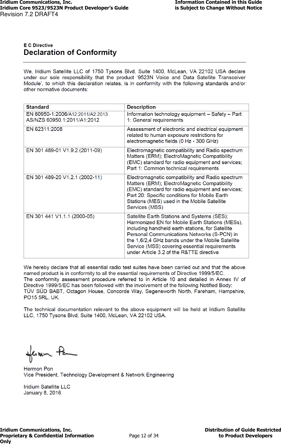
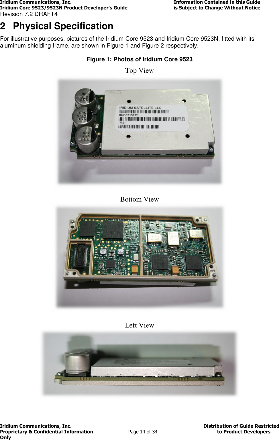
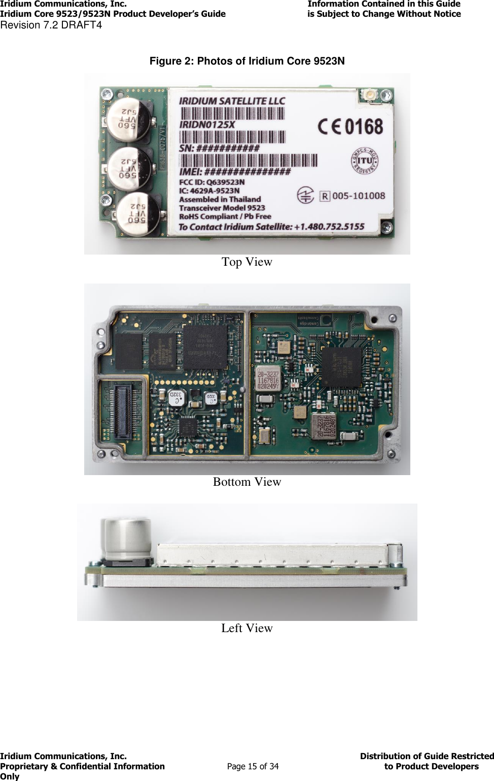
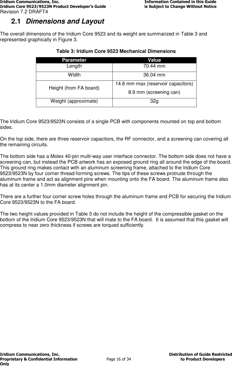
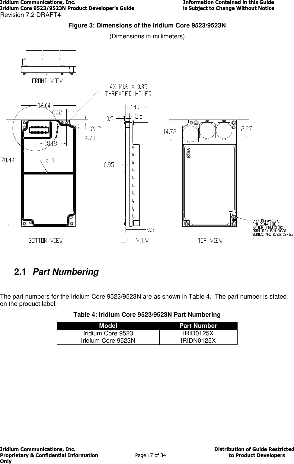
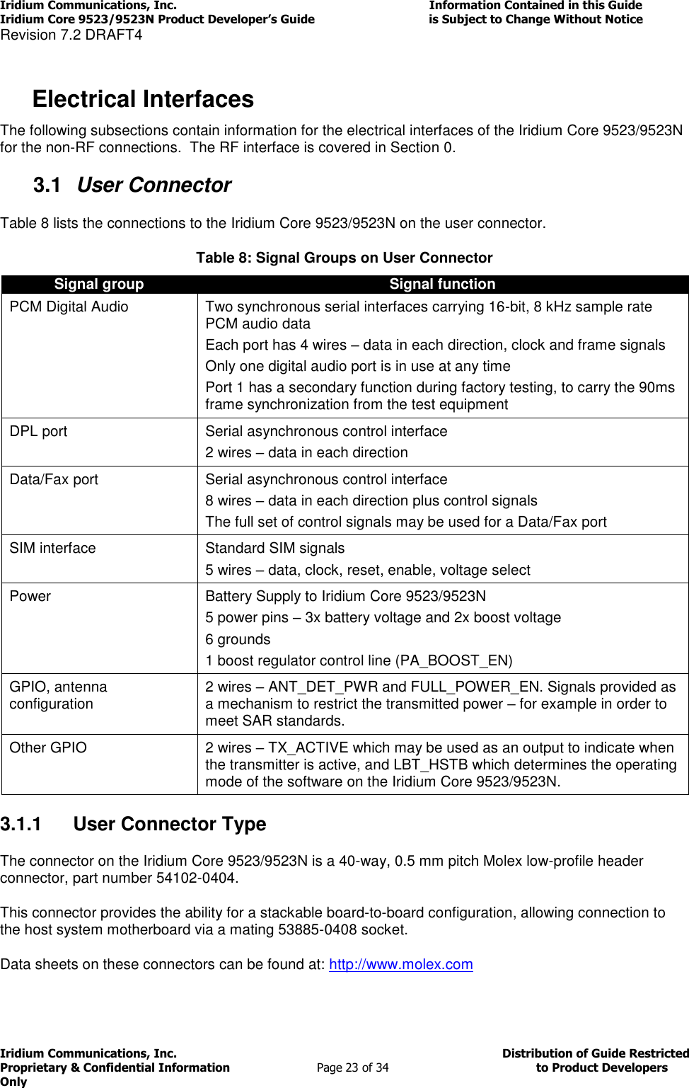
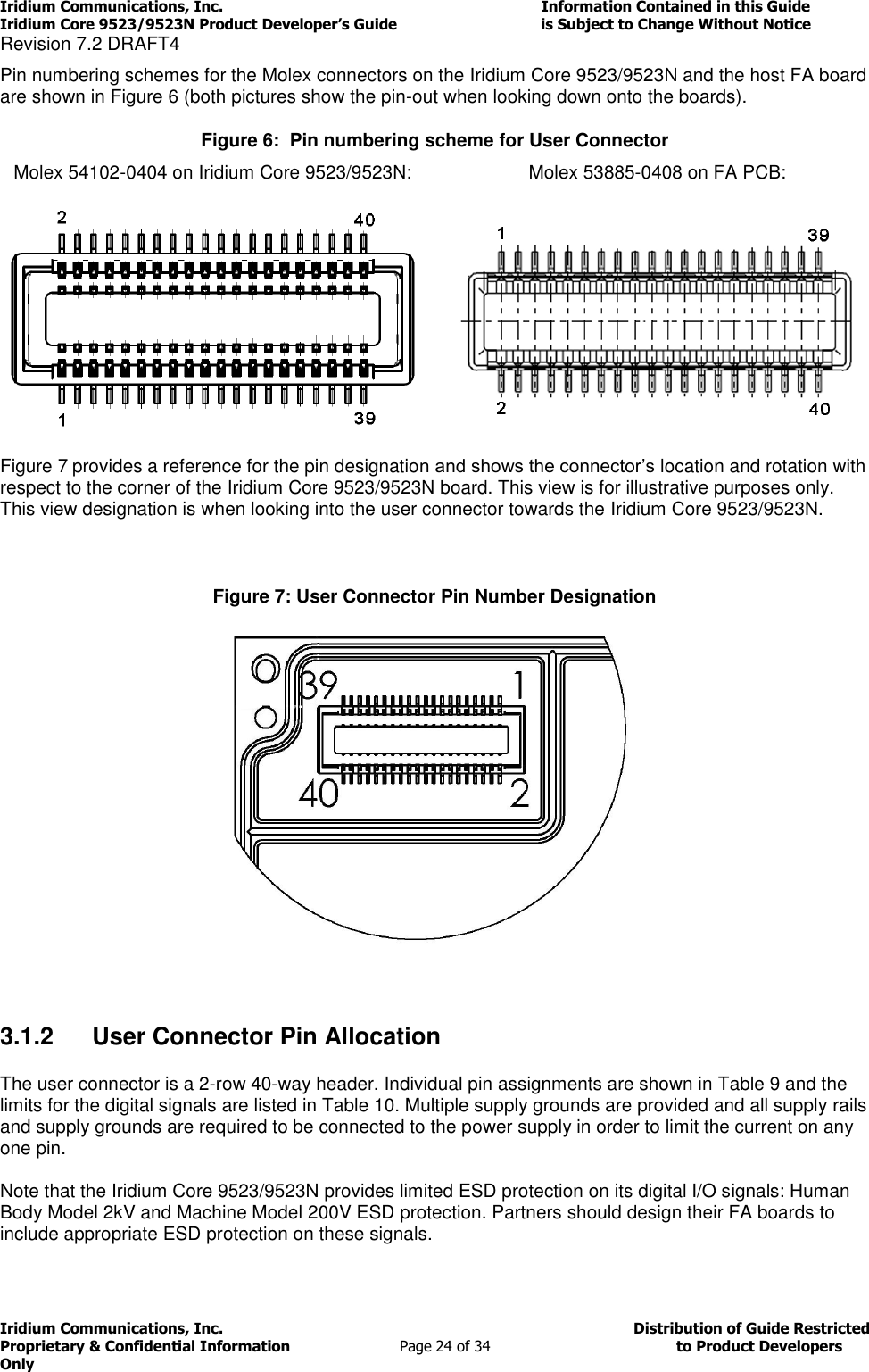
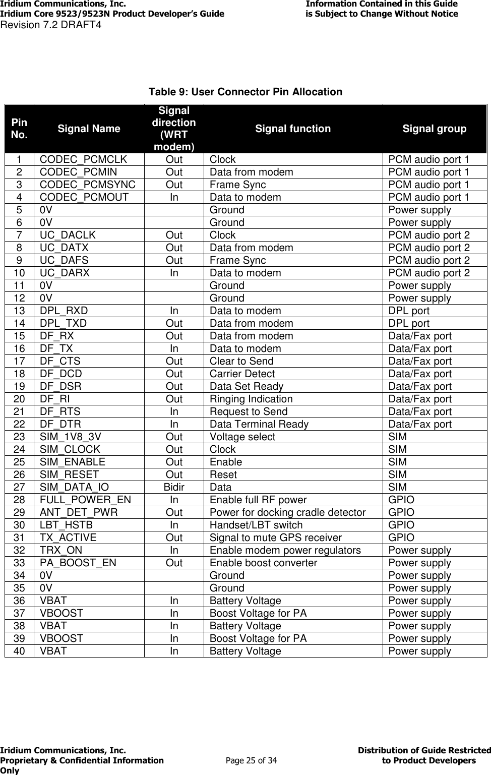
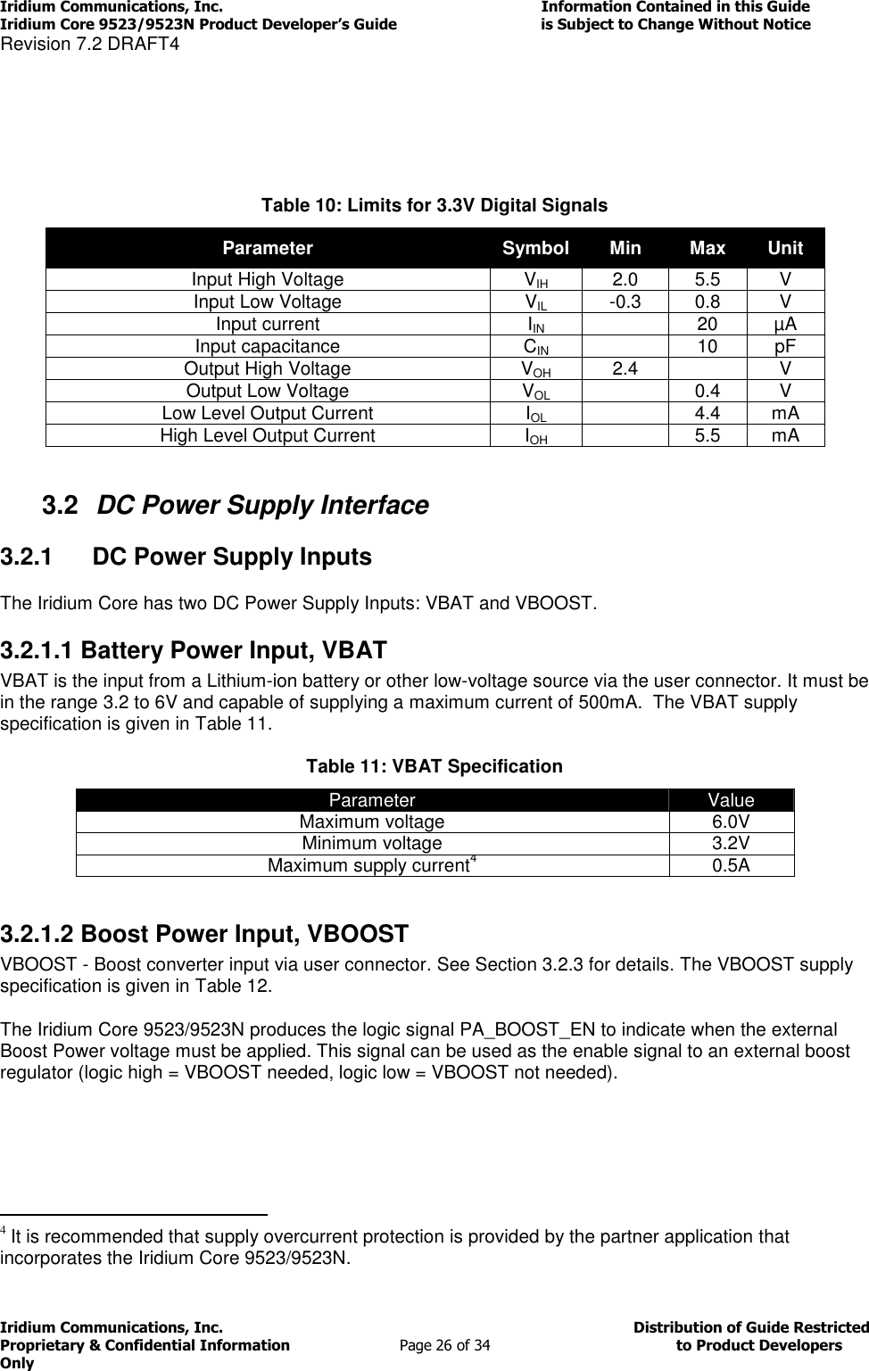
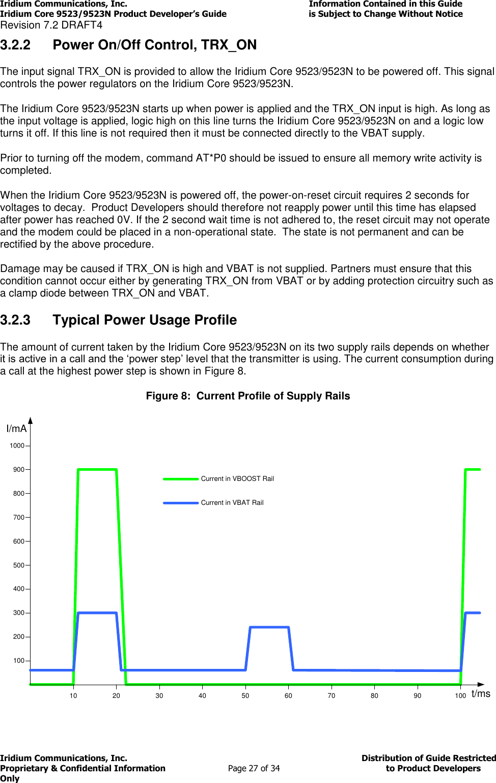
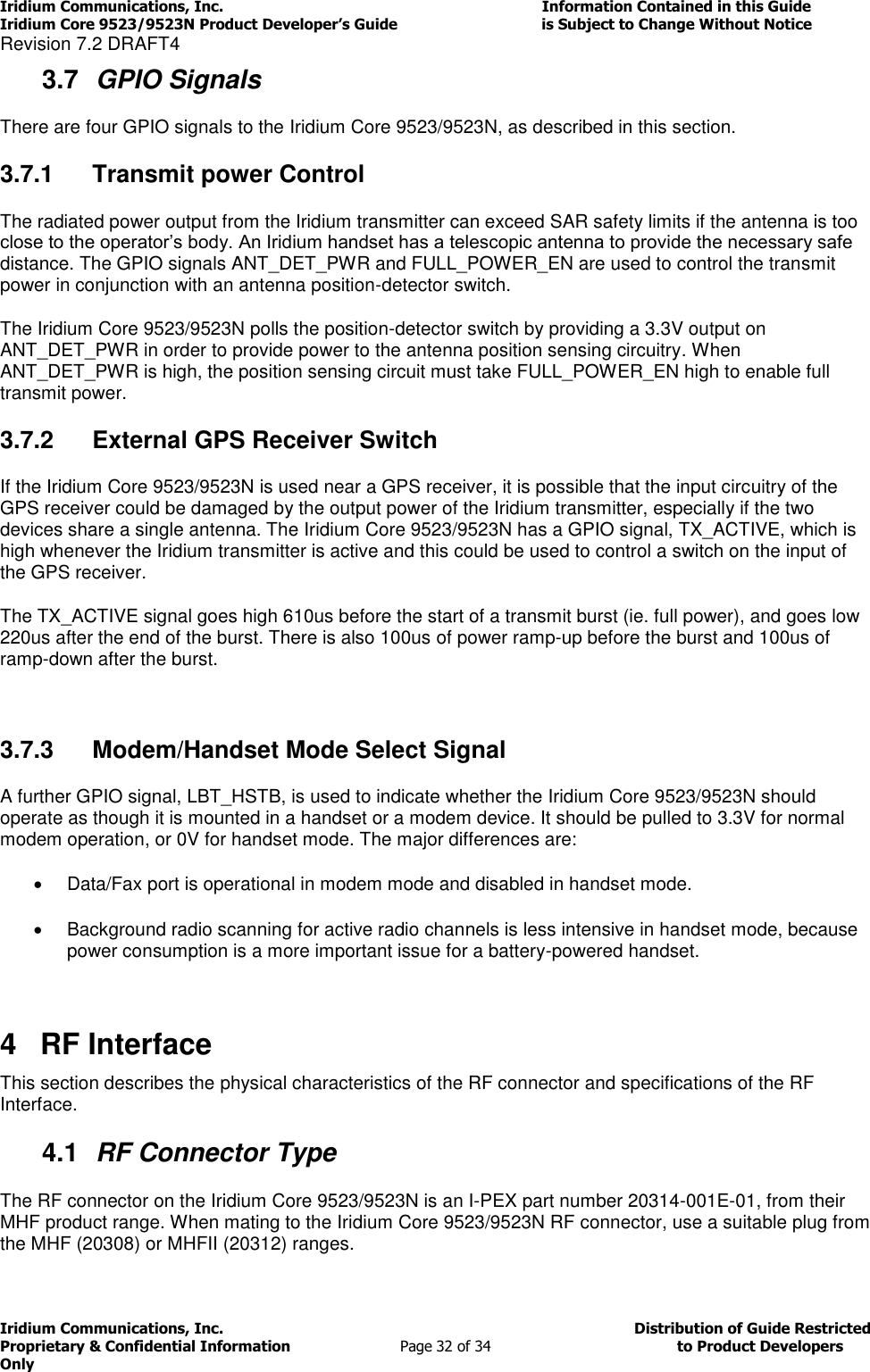
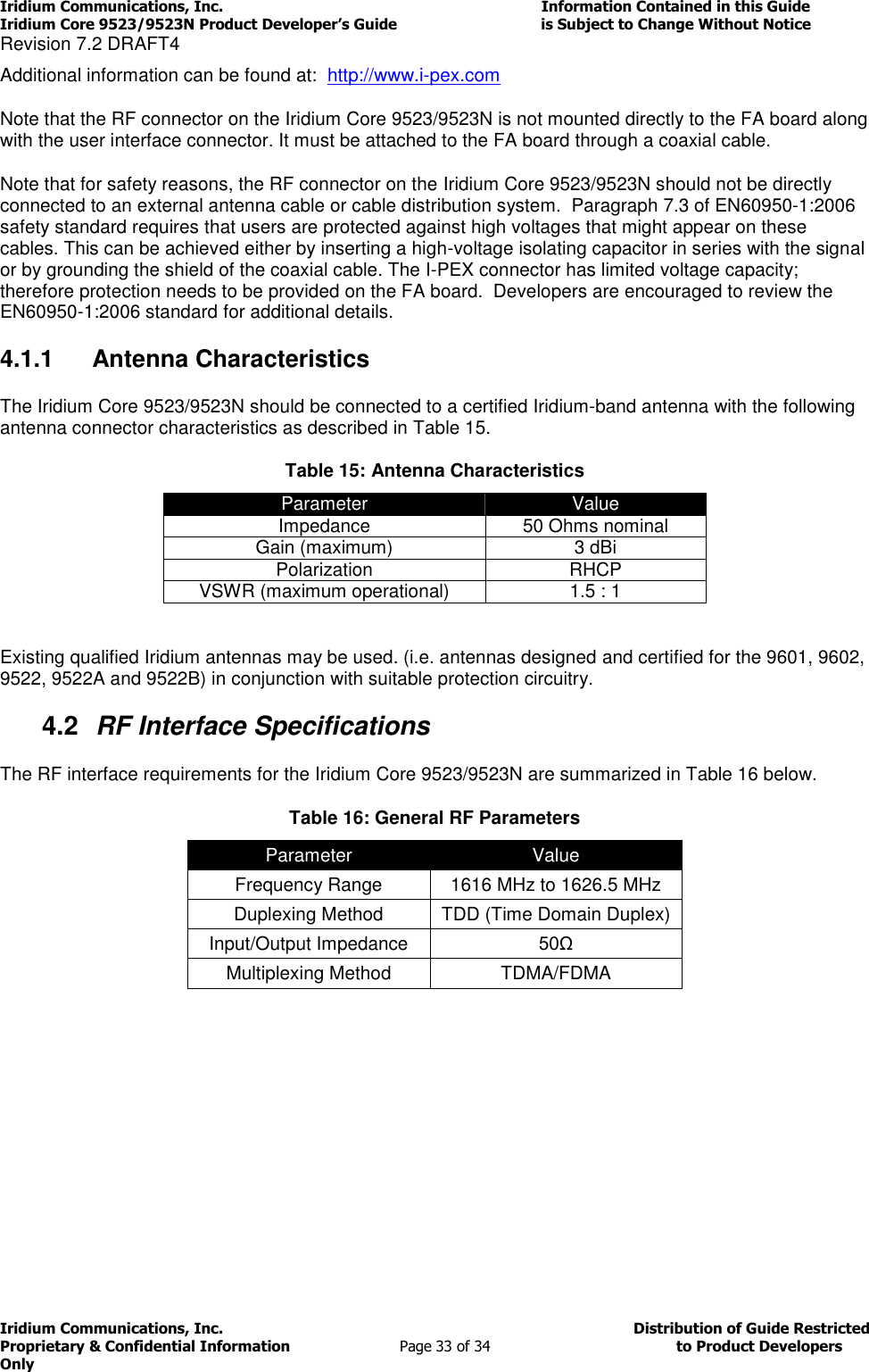
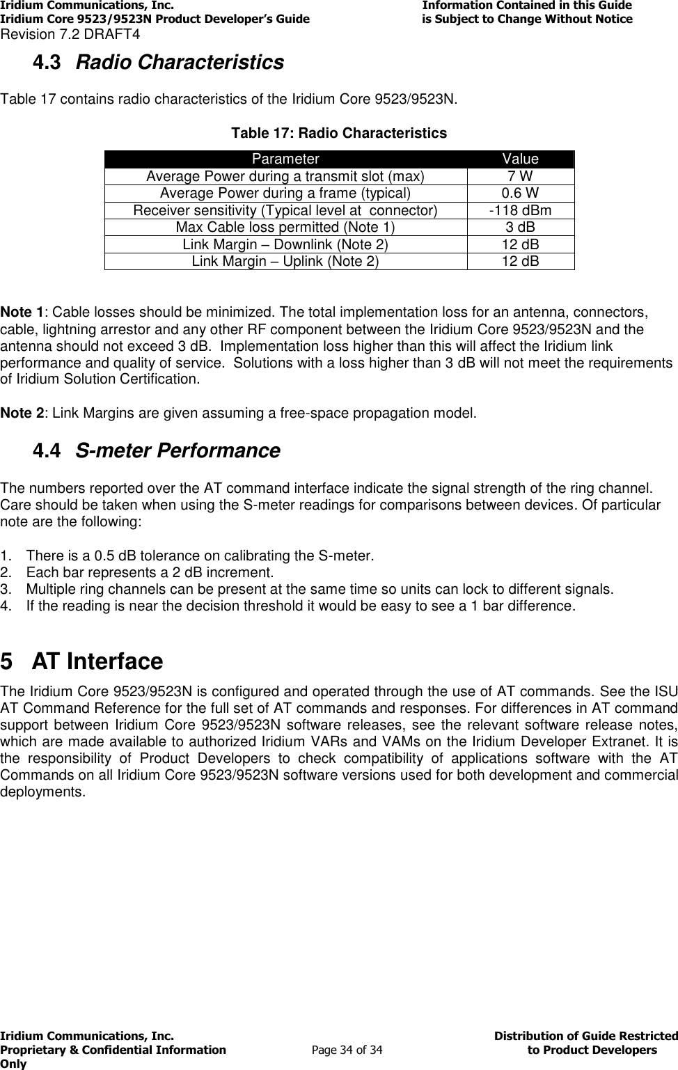
![Iridium Communications, Inc. Information Contained in this Guide Iridium Core 9523/9523N Product Developer’s Guide is Subject to Change Without Notice Revision 7.2 DRAFT4 Iridium Communications, Inc. Distribution of Guide Restricted Proprietary & Confidential Information Page 13 of 34 to Product Developers Only 1.7 Reference [1] ITU-T Recommendation V.25ter, 08/95 [2] ETS 300 642: Digital Cellular Telecommunications System (Phase 2); AT Command Set for GSM Mobile Equipment (GSM 07.07) [3] ETS 300 585: Digital Cellular Telecommunications System (Phase 2); Use of DTE-DCE Interface SMS and CBS (GSM 07.05) [4] ETS 300 520: Digital Cellular Telecommunications System (Phase 2) (GSM); Call Barring (CB) Supplementary Services – Stage 1 (GSM 02.88) [5] ETS 300 511: Digital Cellular Telecommunications System (Phase 2) (GSM); Man–Machine Interface (MMI) of the Mobile Station (MS) (GSM 02.30) [6] ETS 300 516: Digital Cellular Telecommunications System (Phase 2) (GSM); Call Waiting (CW) and Call Hold (HOLD) Supplementary Services; Stage 1 (GSM 02.83) [7] ETS 300 557: Digital Cellular Telecommunications System (Phase 2) (GSM); Mobile radio interface; Layer 3 Specification (GSM 04.08) [8] ETS 300 559: Digital Cellular Telecommunications System (Phase 2) (GSM); Point-to-Point (PP) Short Message Service (SMS) support on mobile radio interface (GSM 04.11) [9] ETS 300 536: Digital Cellular Telecommunications System (Phase 2) (GSM); Technical realization of Short Message Service (SMS) Point-to-Point (PP) (GSM 03.40) [10] ETS 300 537: Digital Cellular Telecommunications System (Phase 2) (GSM); Technical realization of Short Message Service Cell Broadcast (SMSCB) (GSM 03.41) [11] ETS 300 515: Digital Cellular Telecommunications System (Phase 2) (GSM); Call Forwarding (CF) Supplementary Services (GSM 02.82) [12] 3GPP TS 27.007: 3rd Generation Partnership Project; Technical Specification Group Terminals; AT command set for User Equipment (UE)](https://usermanual.wiki/Iridium-Satellite/9523N/User-Guide-2970500-Page-13.png)