Iridium Satellite 9601 Satellite SBD Transceiver module type 9601 User Manual
Iridium Satellite LLC Satellite SBD Transceiver module type 9601
UserManual.wiki
>
Iridium Satellite
>
9601 User Manual
User manual
Navigation menu
Upload a User Manual
Namespaces
Wiki Guide
HTML
PDF
Info
Views
User Manual
Discussion / Help
Navigation
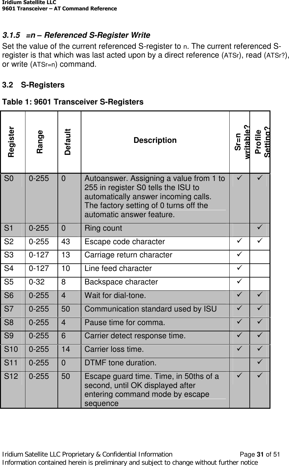
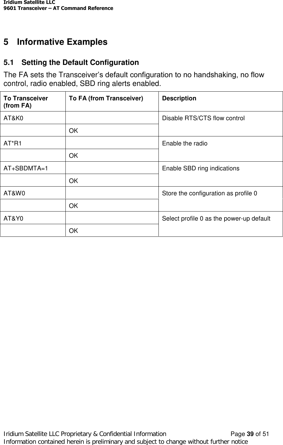
![9601 Short Burst Data Onl y TransceiverPreliminary Product Developers GuideR ev i s io n 1 .2Au gus t 28 t h 2005Iridium Satellite LLC Proprietary & Confidential InformationIridium Satellite LLC6701 Democracy Blvd., Suite 500Bethesda, MD 20817 USAwww.iridium.comToll Free: +1.866.947.4348 [US Only]International +1.480.752.5155email: info@iridium.com](https://usermanual.wiki/Iridium-Satellite/9601/User-Guide-601743-Page-1.png)
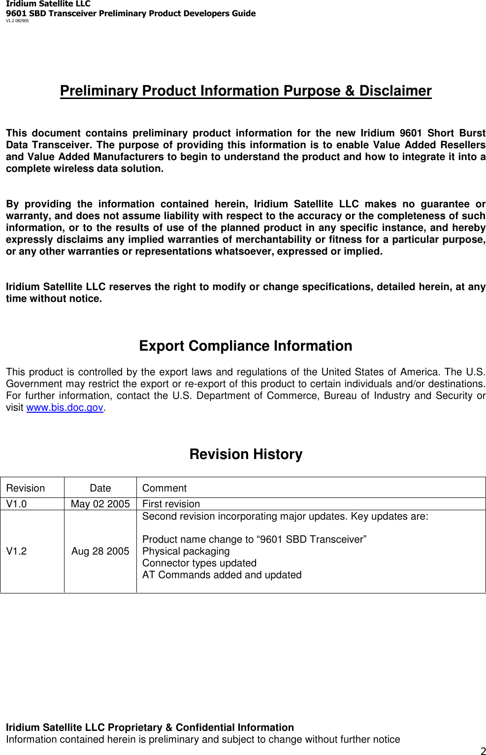
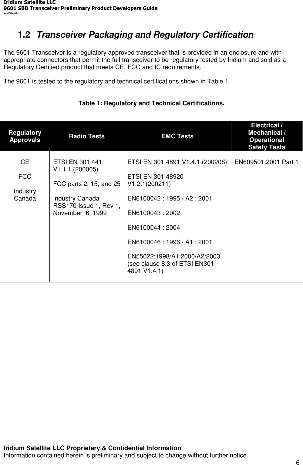
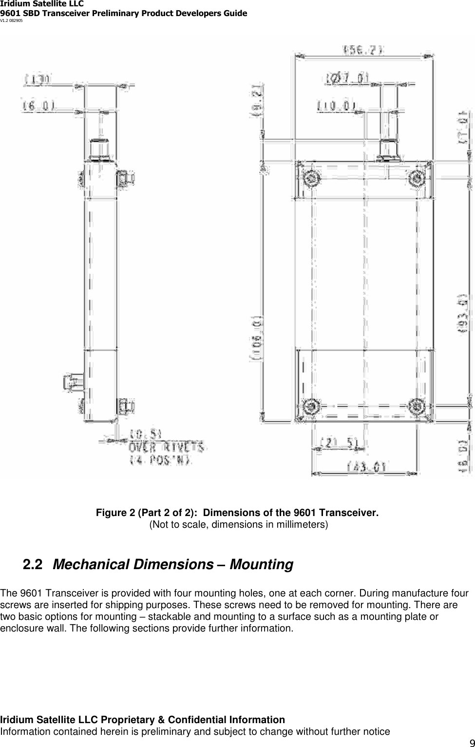
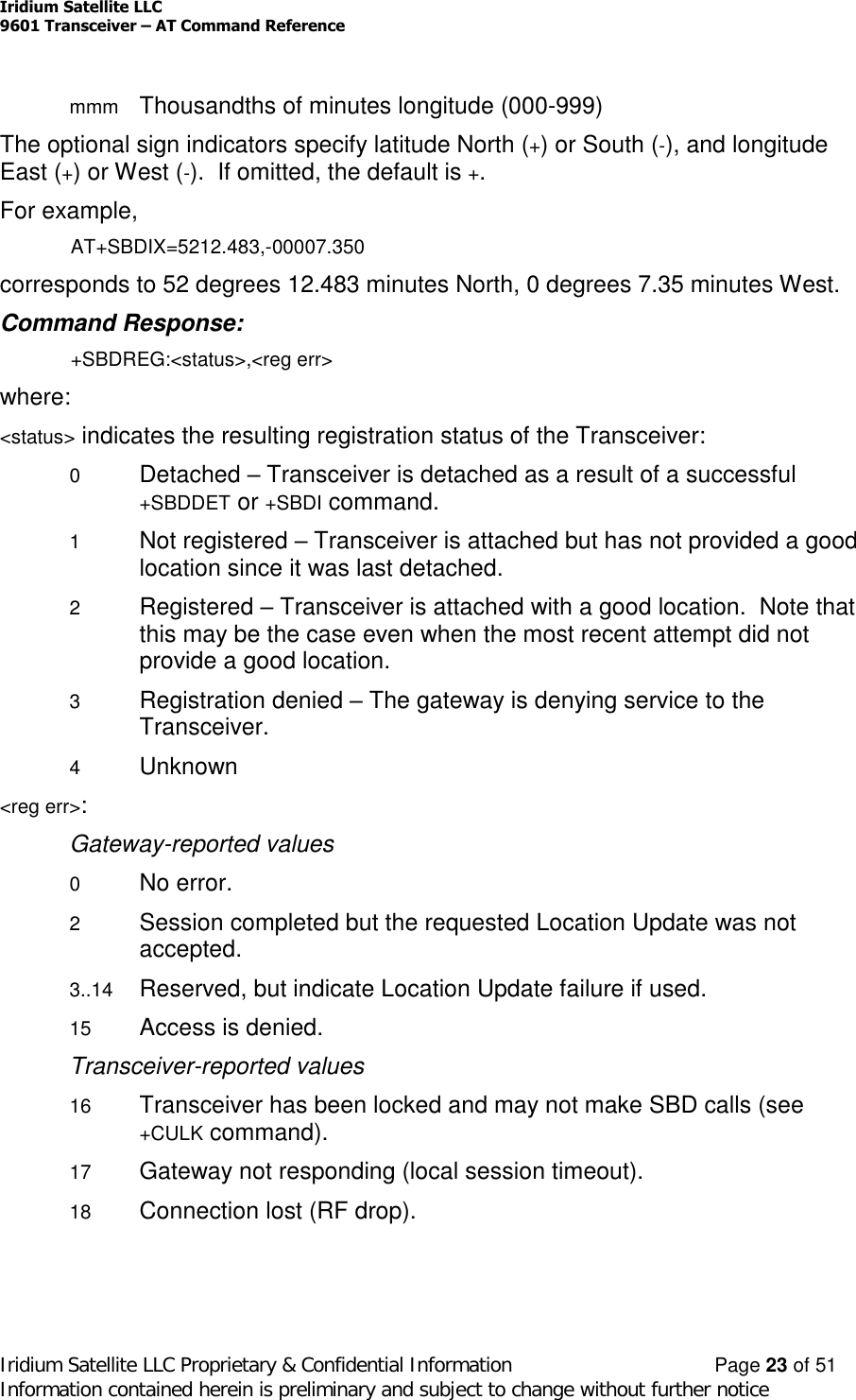
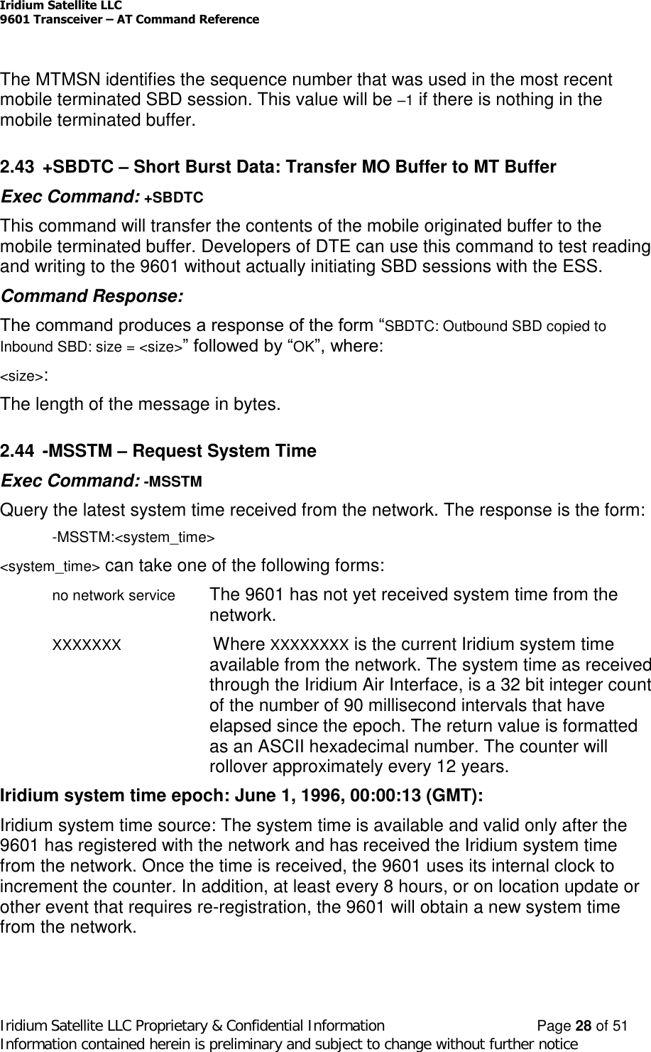
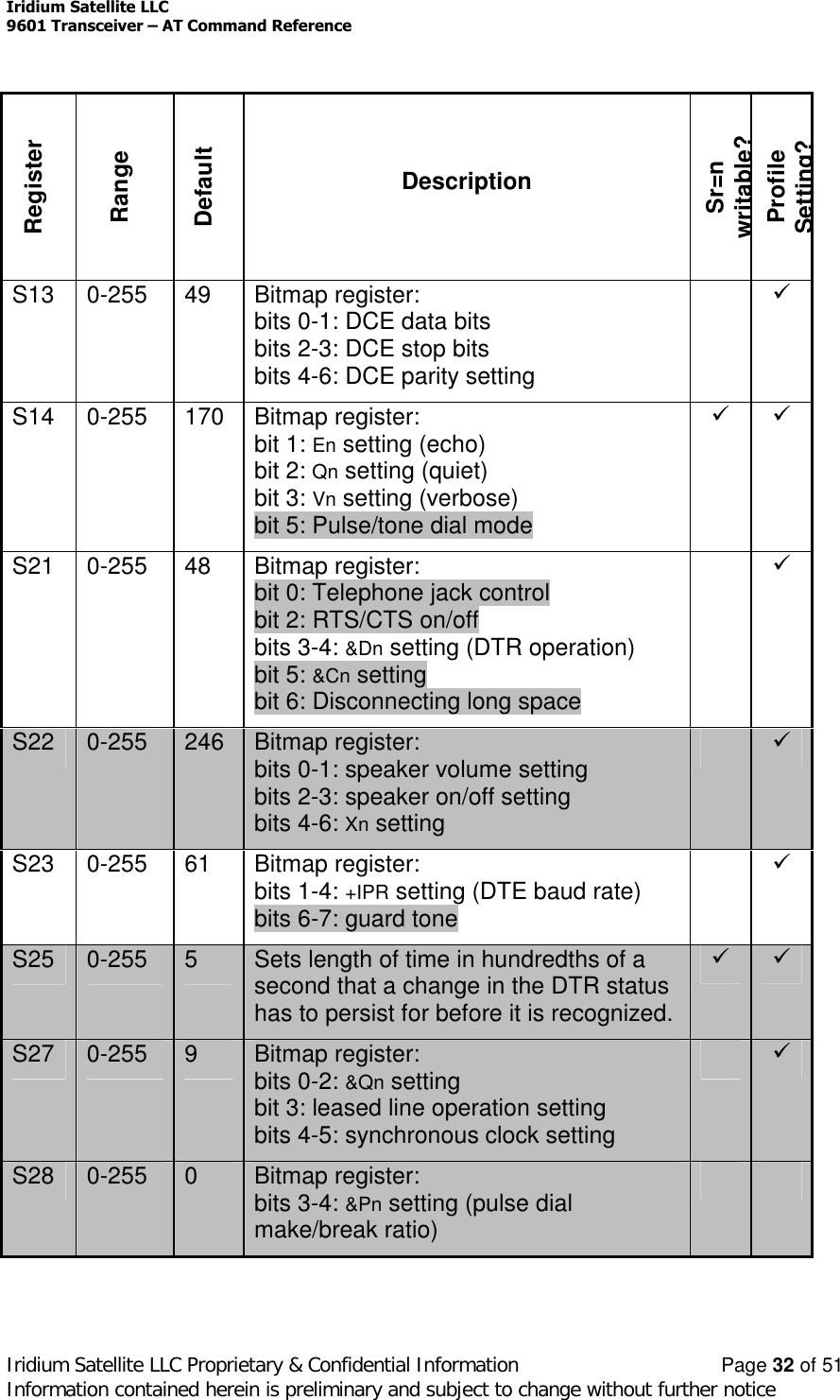
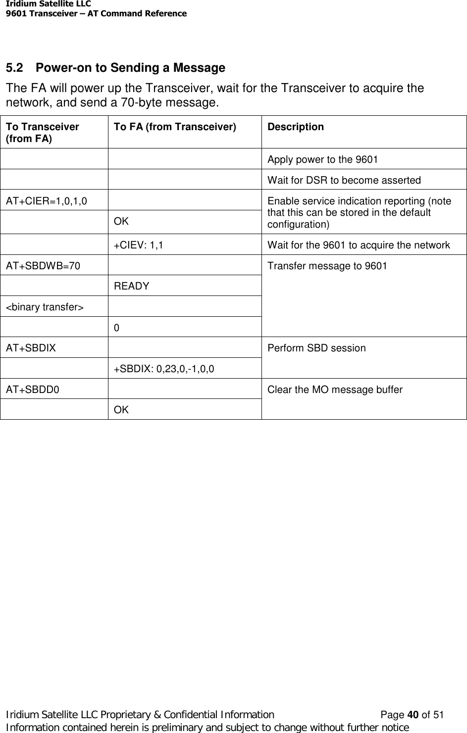
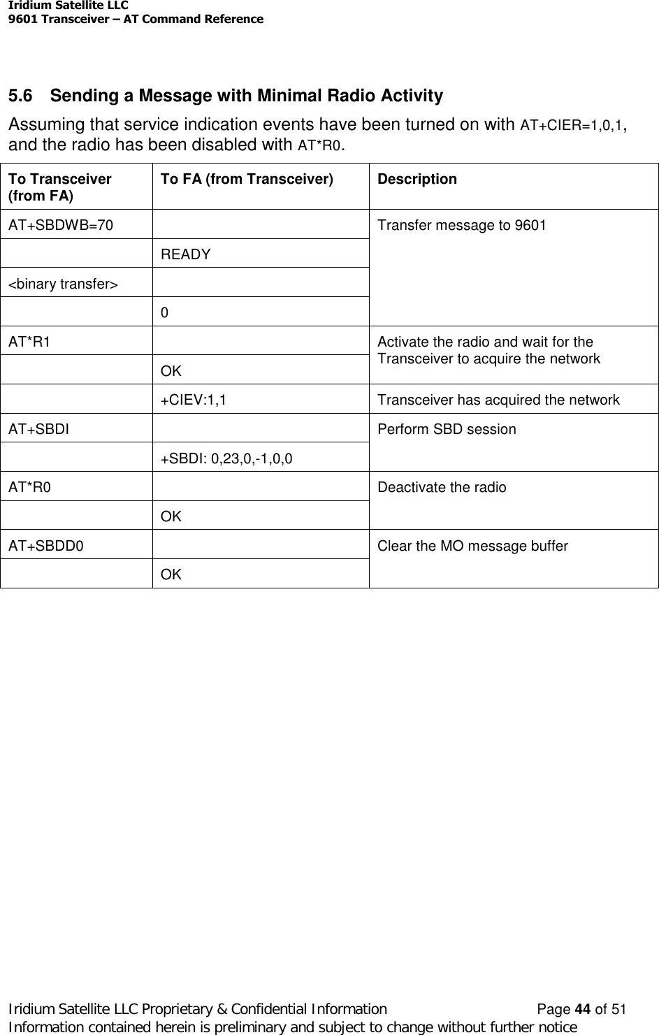
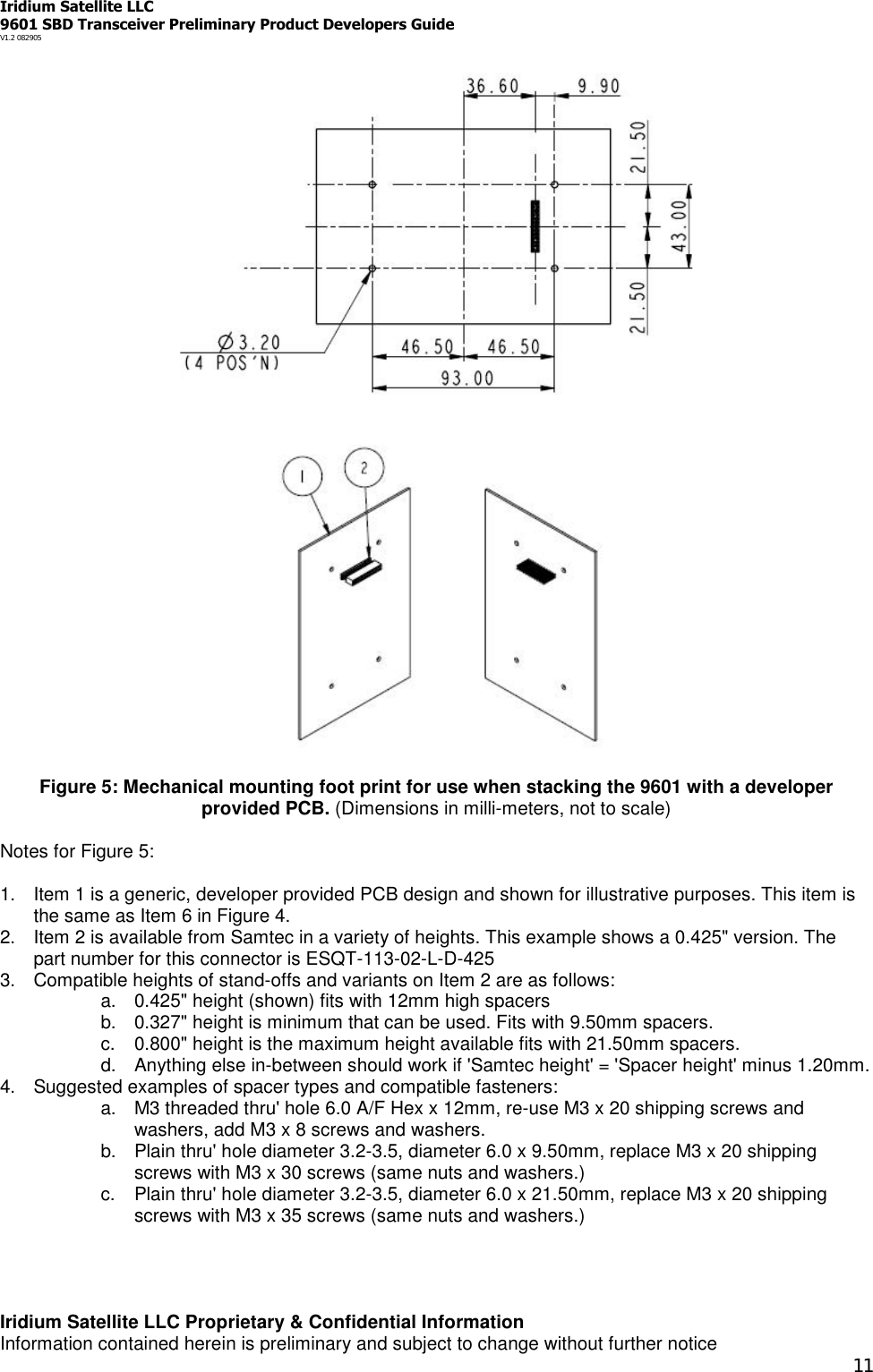
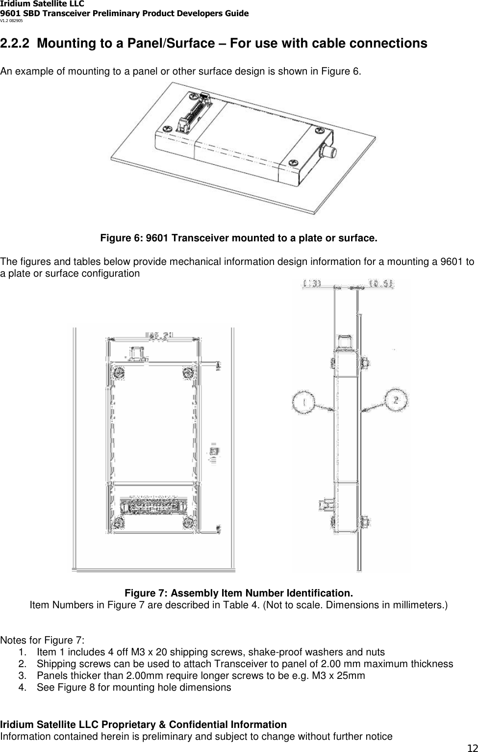
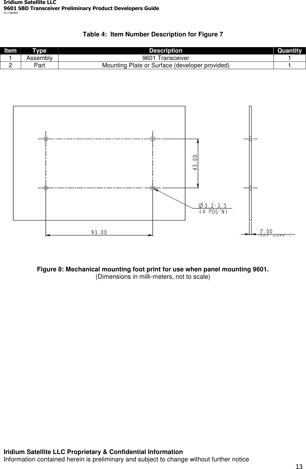
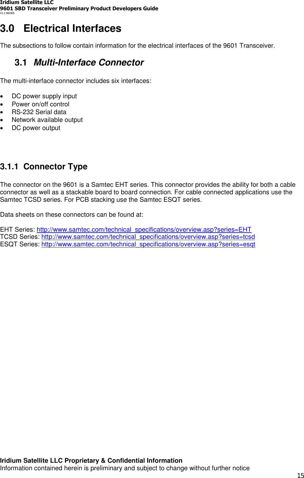
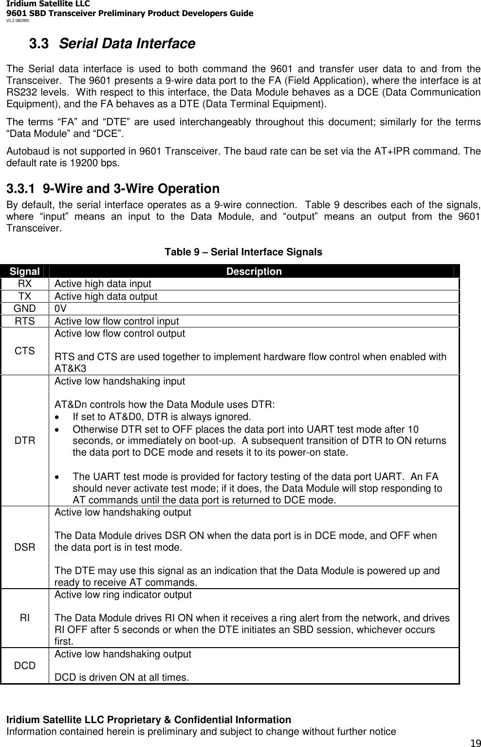
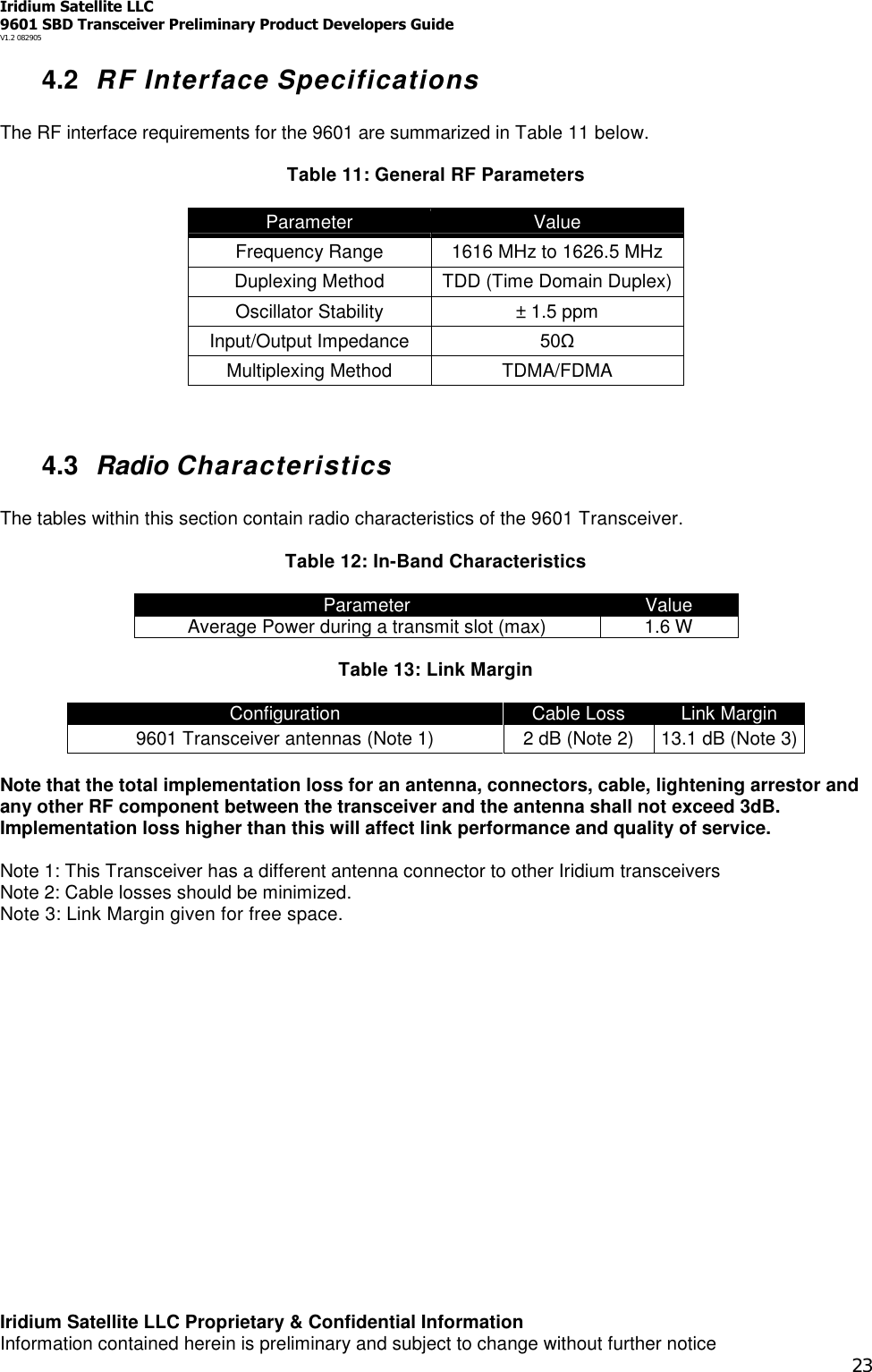
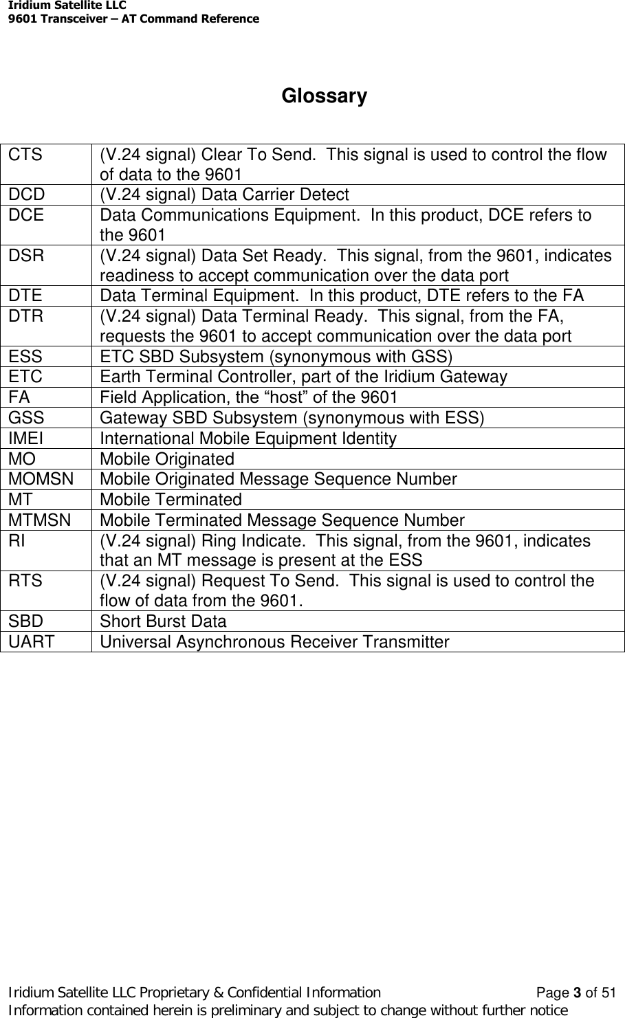
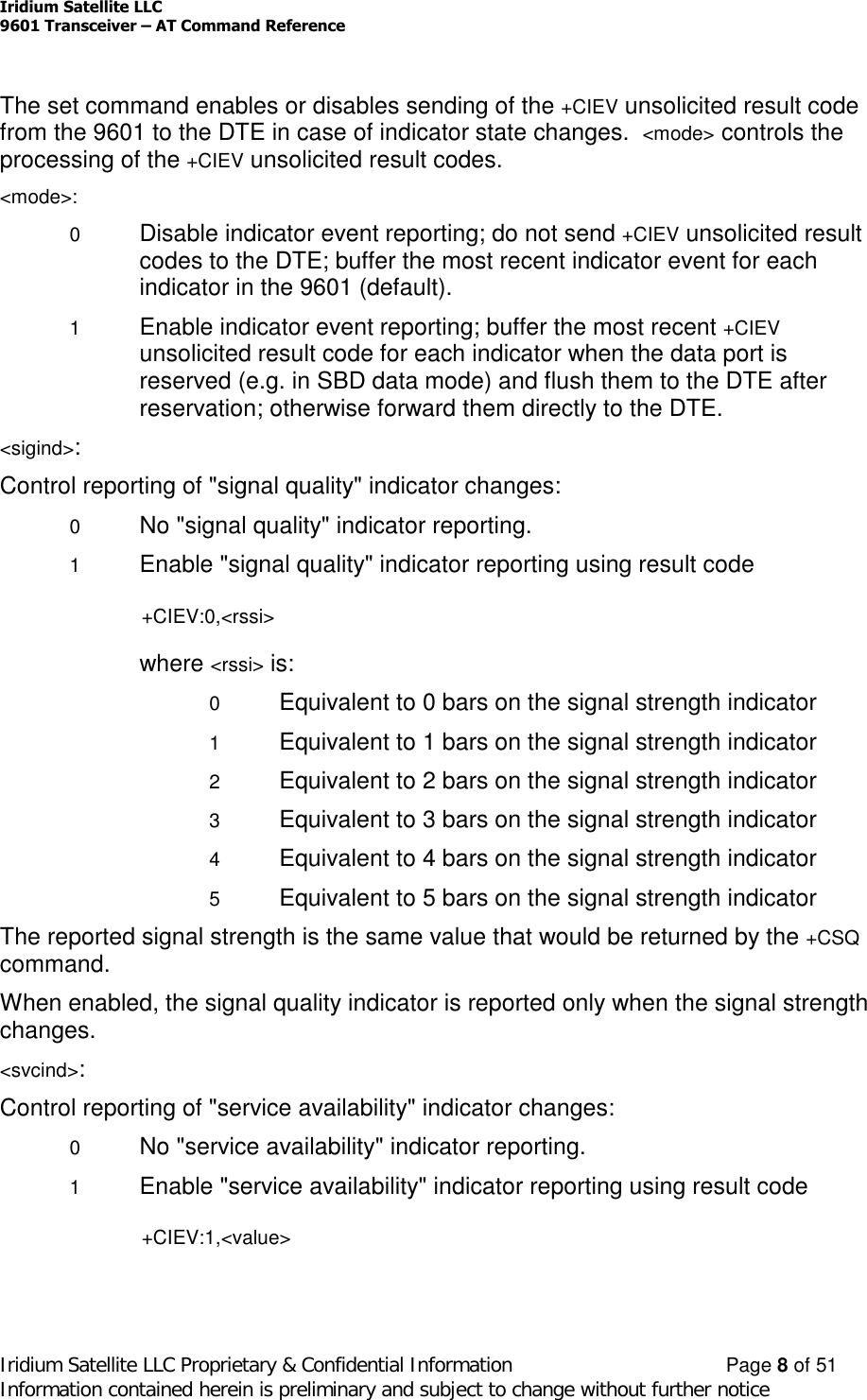
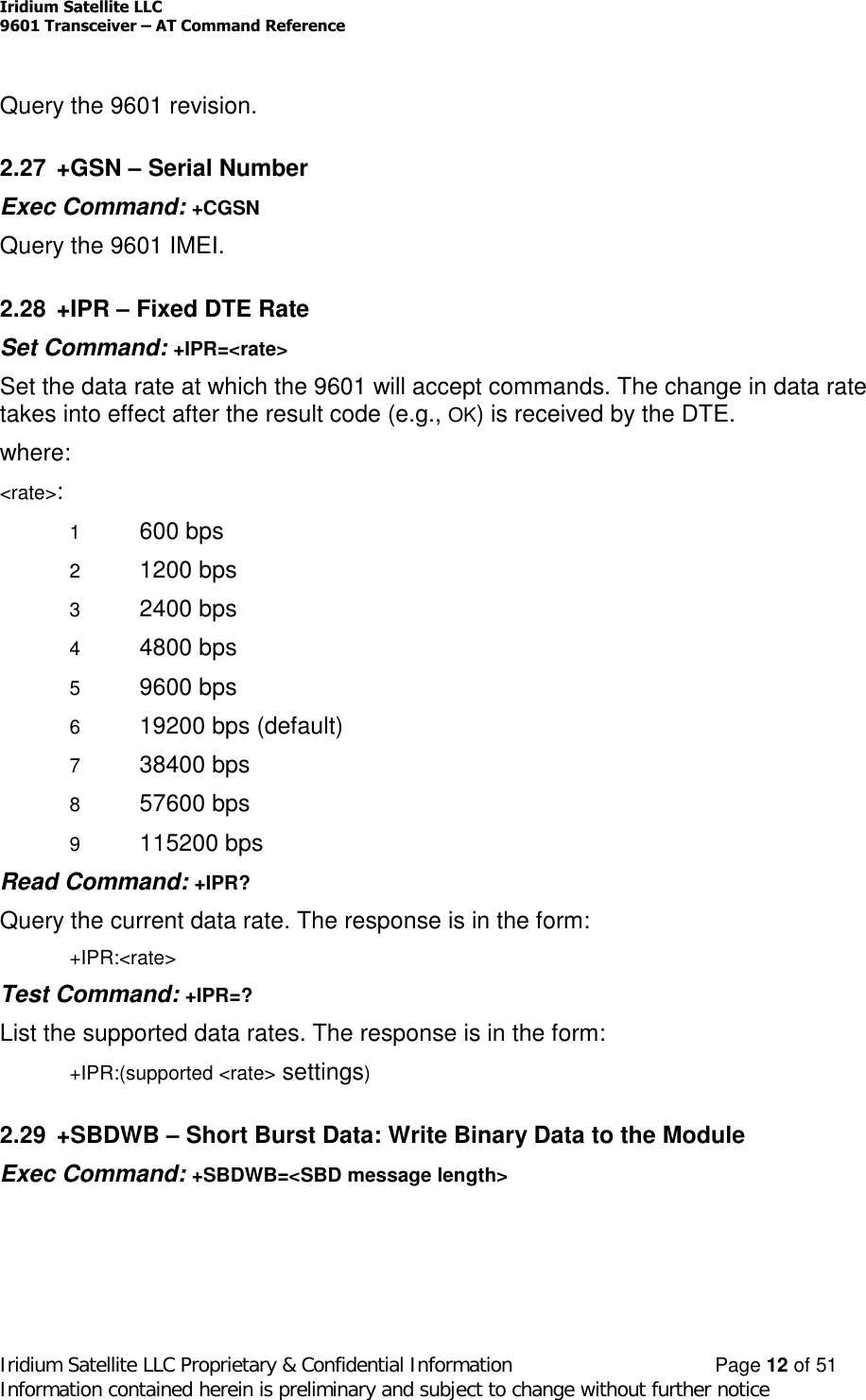
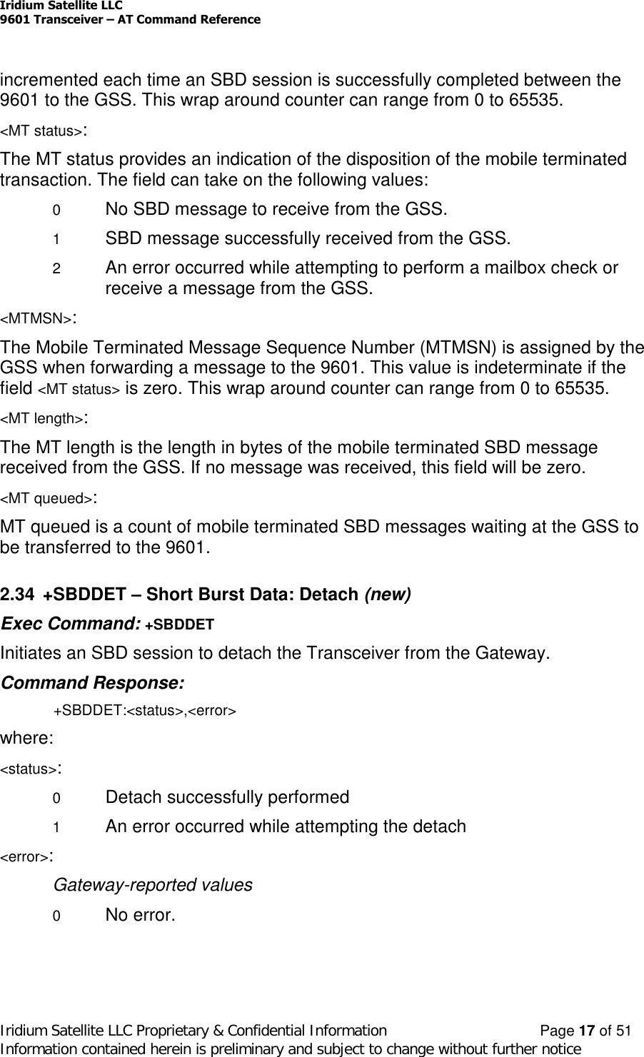
![Iridium Satellite LLC9601 SBD Transceiver Preliminary Product Developers GuideV1.2 082905Iridium Satellite LLC Proprietary & Confidential InformationInformation contained herein is preliminary and subject to change without further notice102.2.1 Mounting - Stackable DesignAn example stackable design is shown in Figure 3.Figure 3: 9601 Transceiver mounted to a unpopulated PCB.The figures and tables below provides mechanical information design information for a suitable‘stackable’ 9601 to developer PCB configurationFigure 4: Assembly Item Number Identification.Item Numbers in Figure 4 are described in Table 3. Not to scale. Dimensions in millimeters.Table 3: Item Number Description for Figure 4Item Type Description Quantity1 Assembly 9601 Transceiver 12 Part M3 Shake-proof washer, zinc plated steel [4 supplied with item 1] 83 Part M3 x 20 Pan head screw, pozidrive, zinc plated steel [4 supplied with item 1] 44 Part M3 Threaded standoff, 6.0 A/F HEX x 12.00 mm 45 Part M3 x 8 Pan head screw, pozidrive, zinc plated steel 46 Assembly Solution developer PCB fitted with Samtec connector ESQT-113-02-L-D-425.[This item is the same item as Item 1 in Figure 5.] 1](https://usermanual.wiki/Iridium-Satellite/9601/User-Guide-601743-Page-10.png)
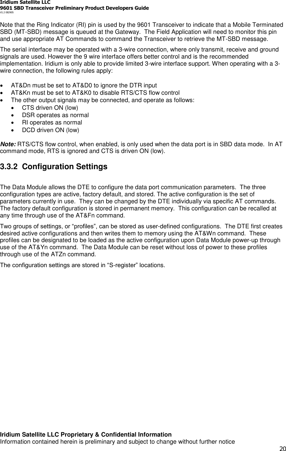
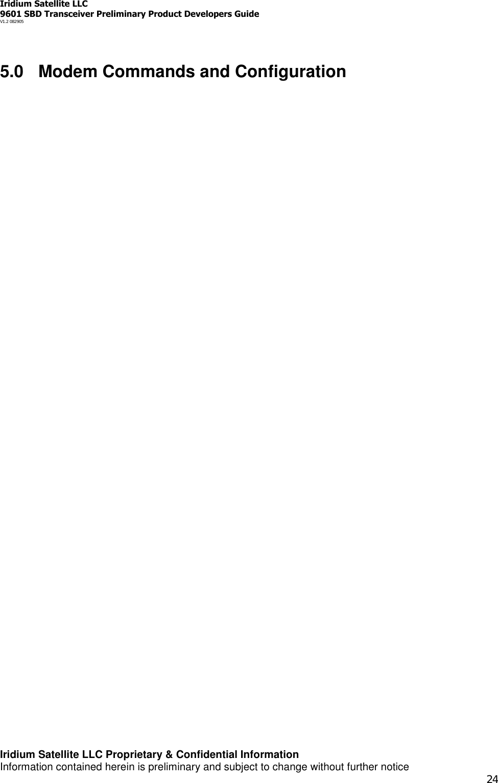
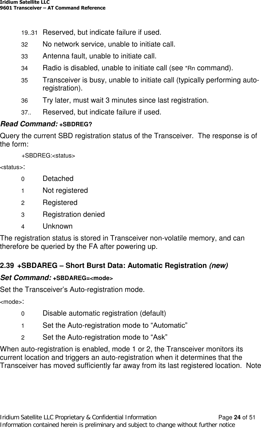
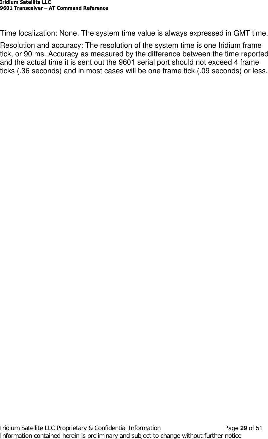
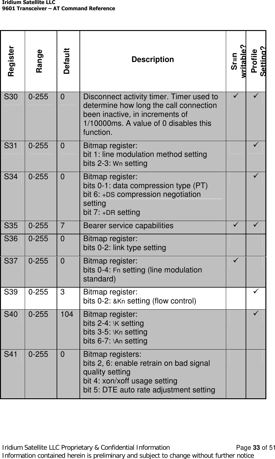
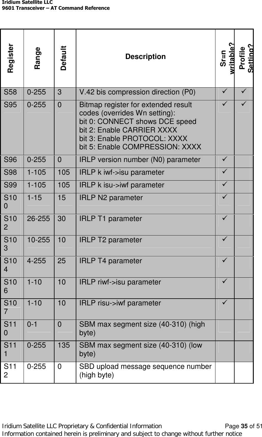
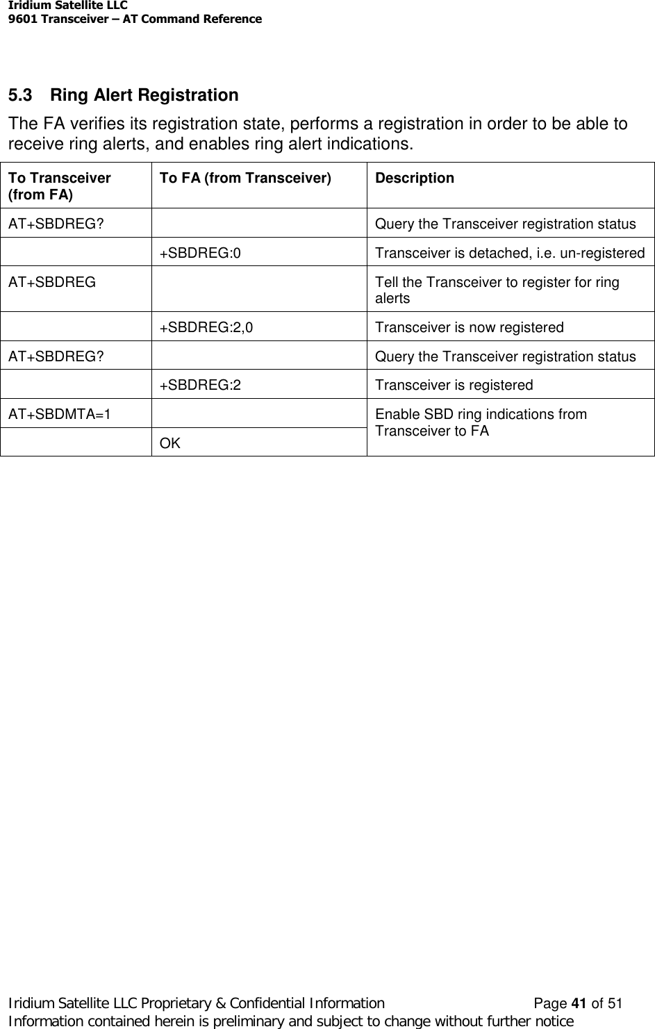
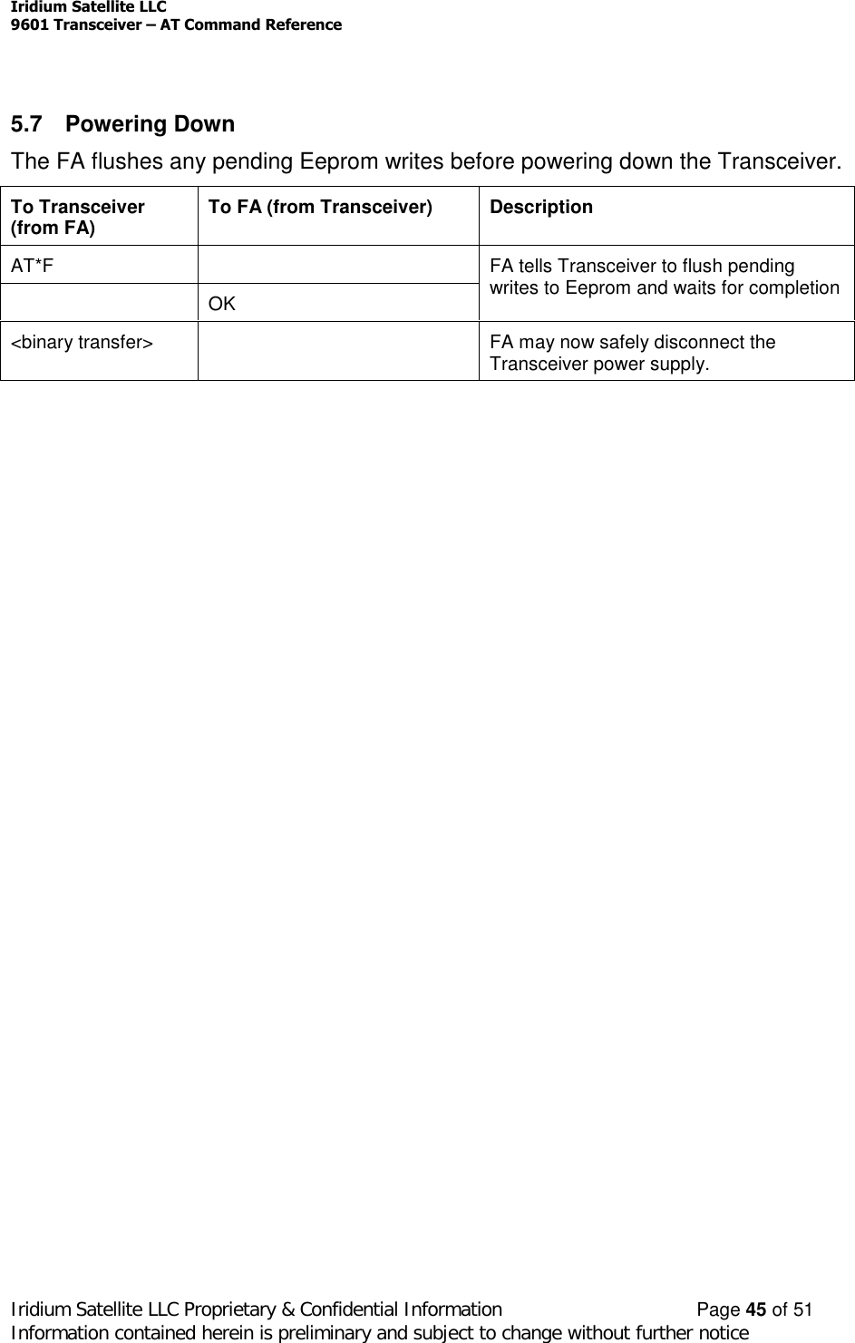
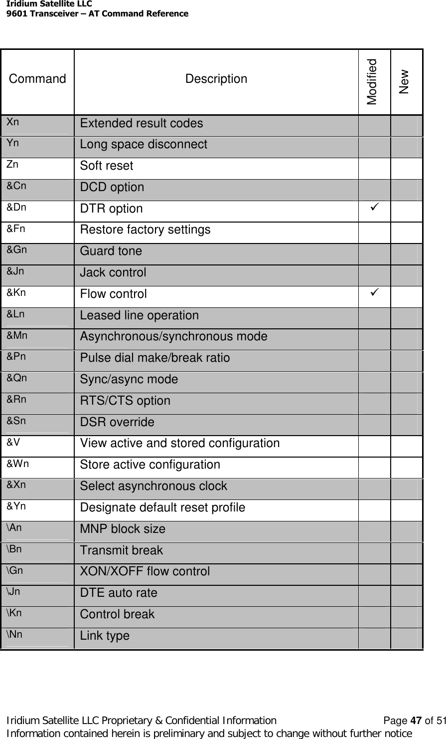
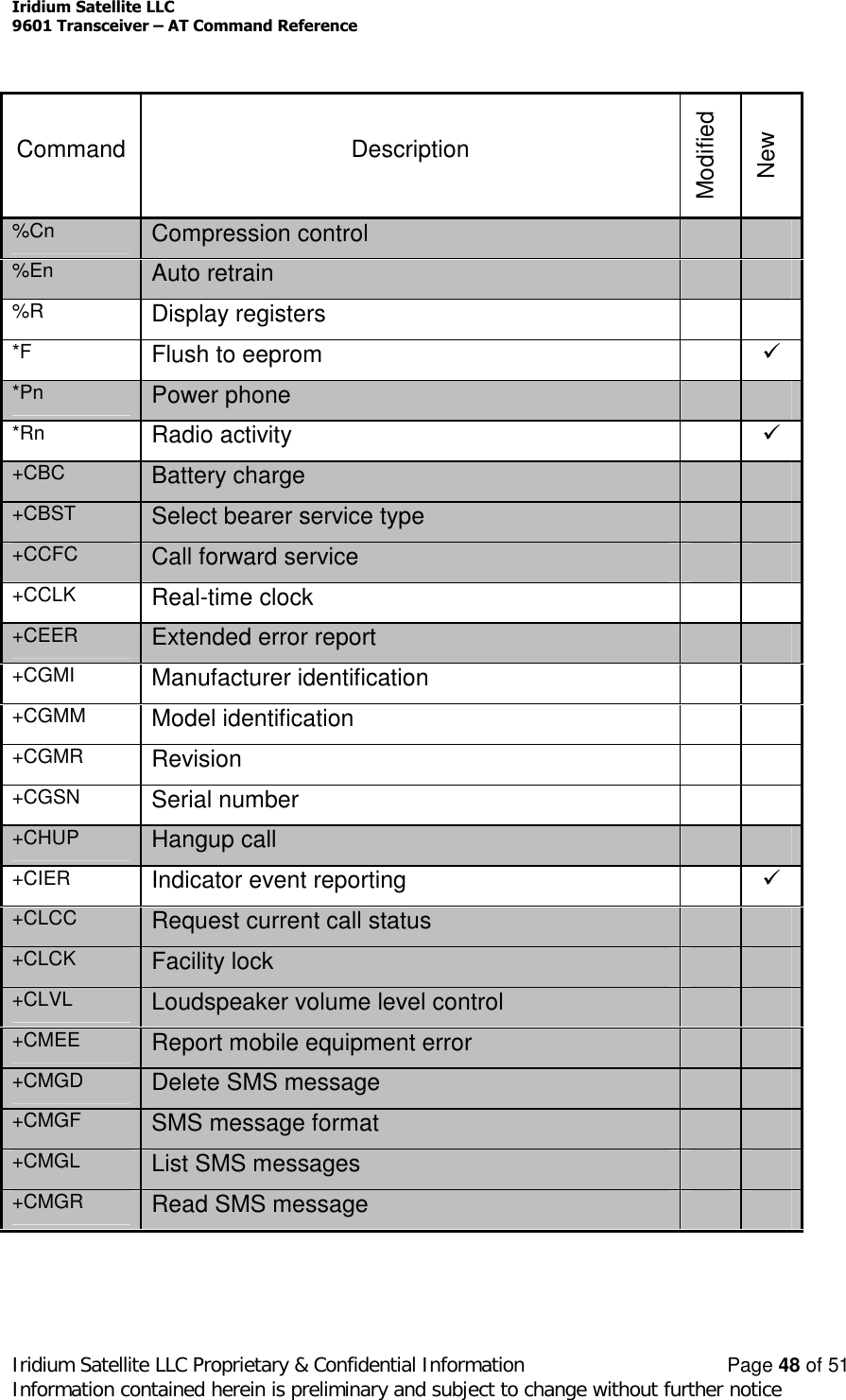
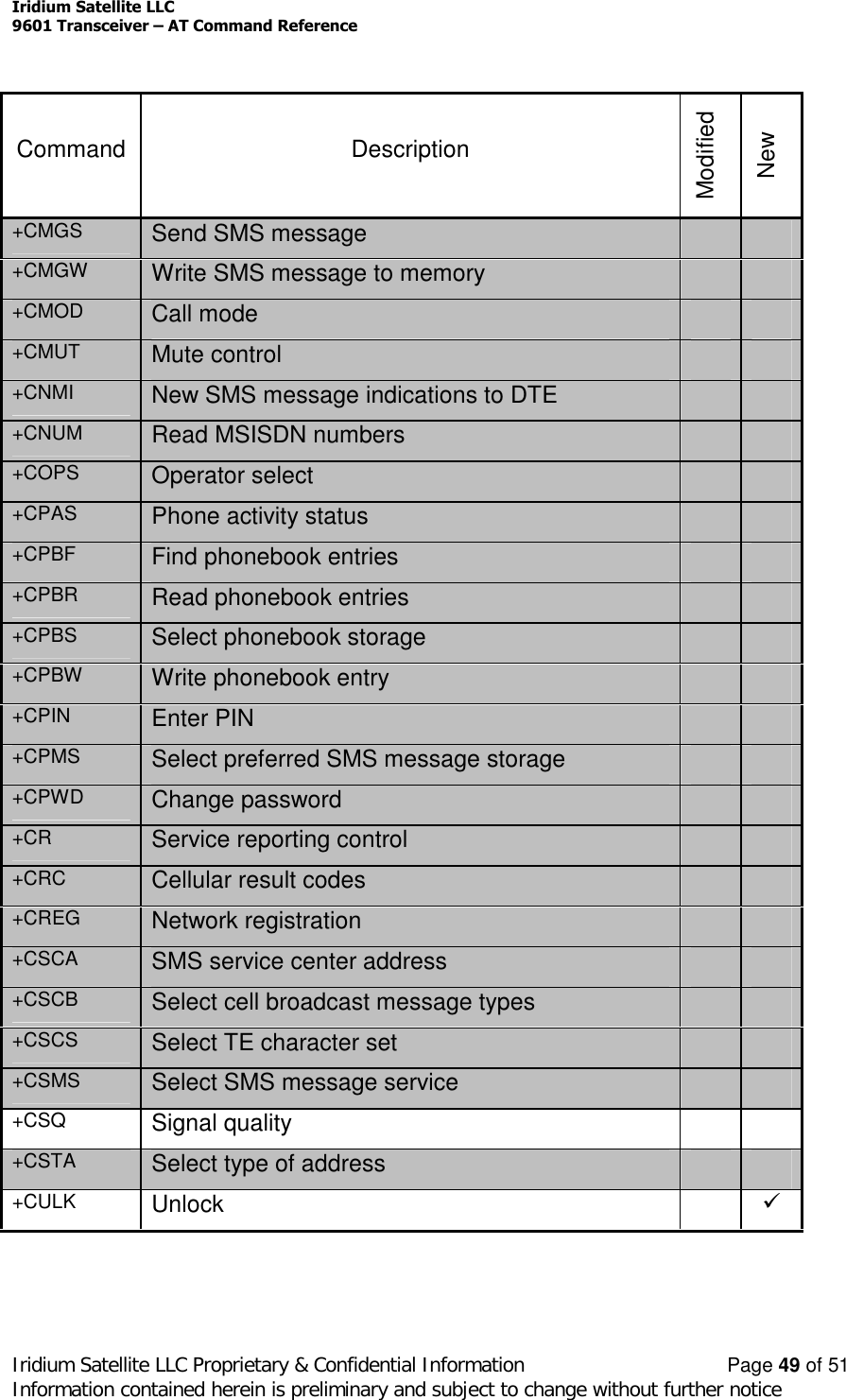
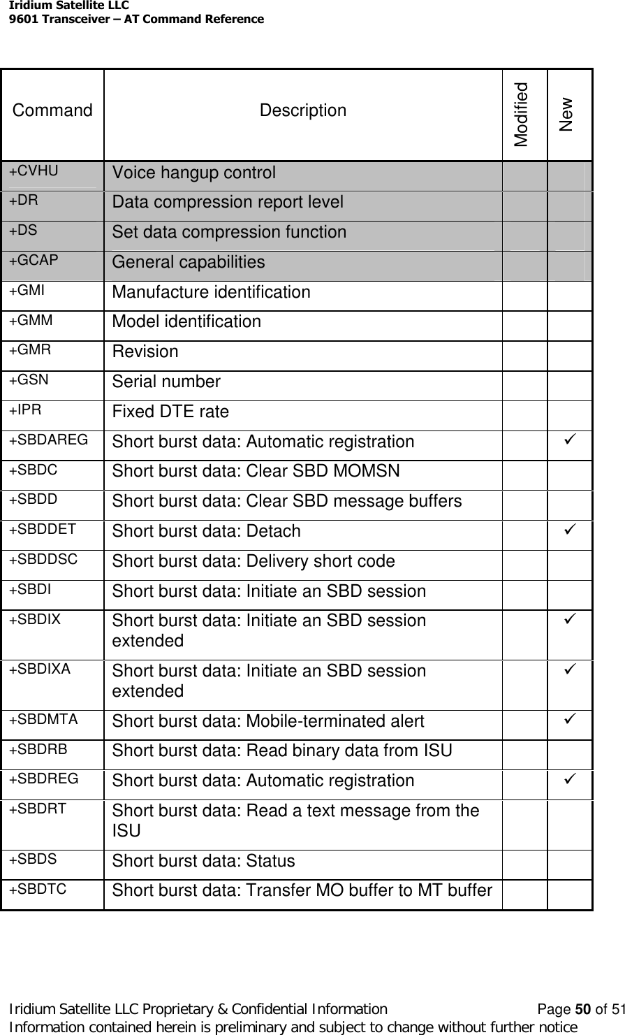
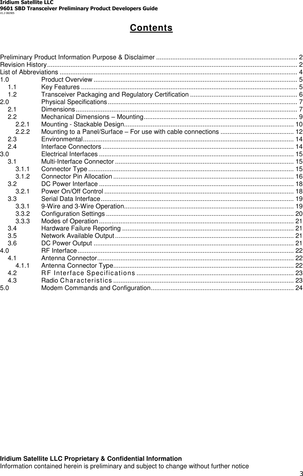
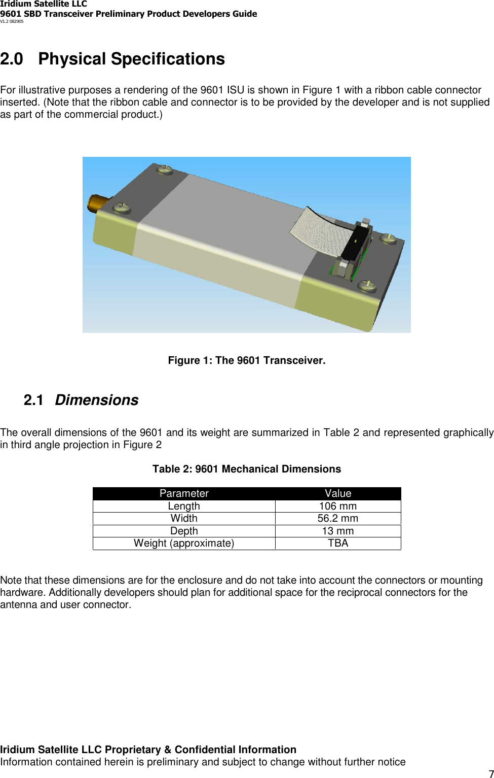
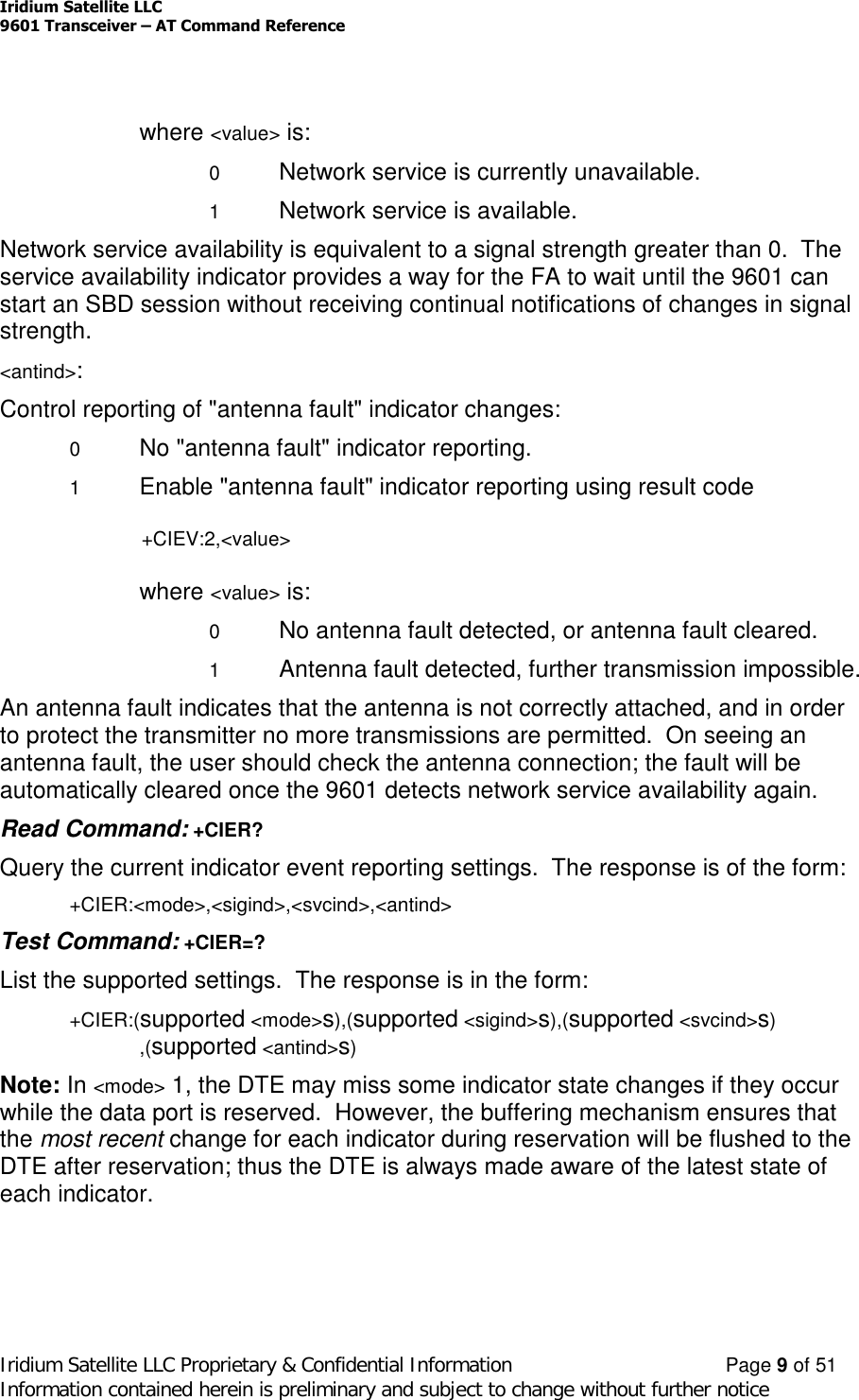
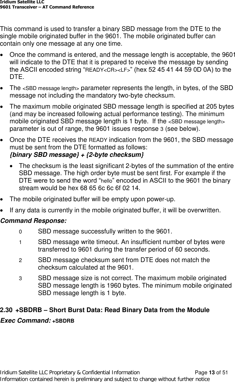
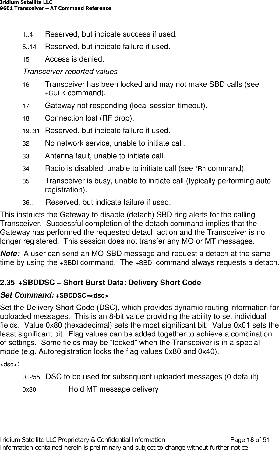
![Iridium Satellite LLC9601 Transceiver –AT Command ReferenceIridium Satellite LLC Proprietary & Confidential Information Page 7of 51Information contained herein is preliminary and subject to change without further notice2.16 *Rn –Radio Activity (new)Control radio activity.0Disable radio activity.1Enable radio activity (default).While the radio is disabled:SBD sessions can not be initiated; they will fail immediately.No SBDRING alerts will be issued for automatic-MT messages.No registration, i.e. location updates will be performed.The baseband circuitry is still active and the 9601 still accepts AT commands.This command allows the FA to reduce detectable emissions from the RF circuitryduring the idle periods between SBD sessions, and also provides a degree ofpower saving in cases where it may be inconvenient for the FA to power down the9601.2.17 +CGMI –Manufacturer IdentificationExec Command: +CGMIQuery the 9601 manufacturer.2.18 +CGMM –Model IdentificationExec Command: +CGMMQuery the 9601 model.2.19 +CGMR –RevisionExec Command: +CGMRQuery the 9601 revision.2.20 +CGSN –Serial NumberExec Command: +CGSNQuery the 9601 IMEI.2.21 +CIER –Indicator Event Reporting (new)Set Command: +CIER=[<mode>[,<sigind>[,<svcind>[,<antind>]]]]](https://usermanual.wiki/Iridium-Satellite/9601/User-Guide-601743-Page-31.png)
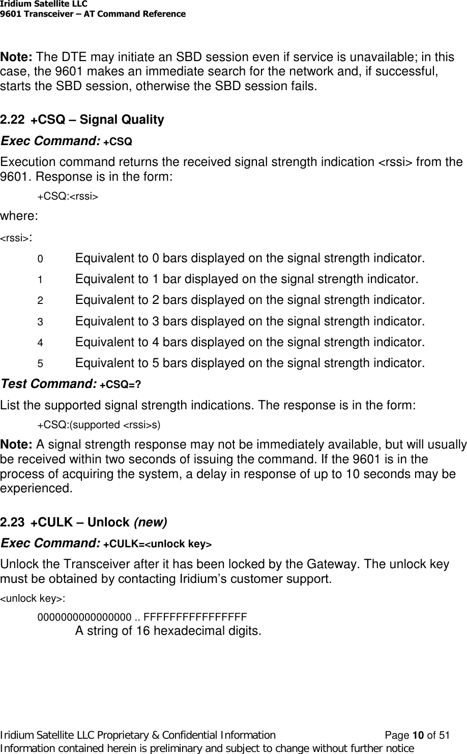
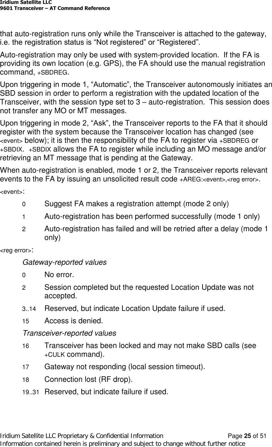
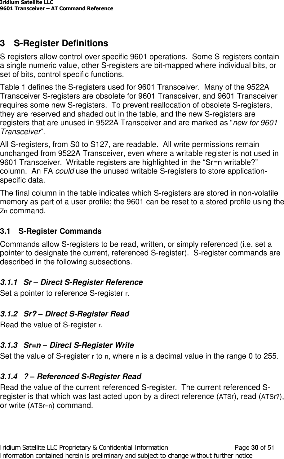
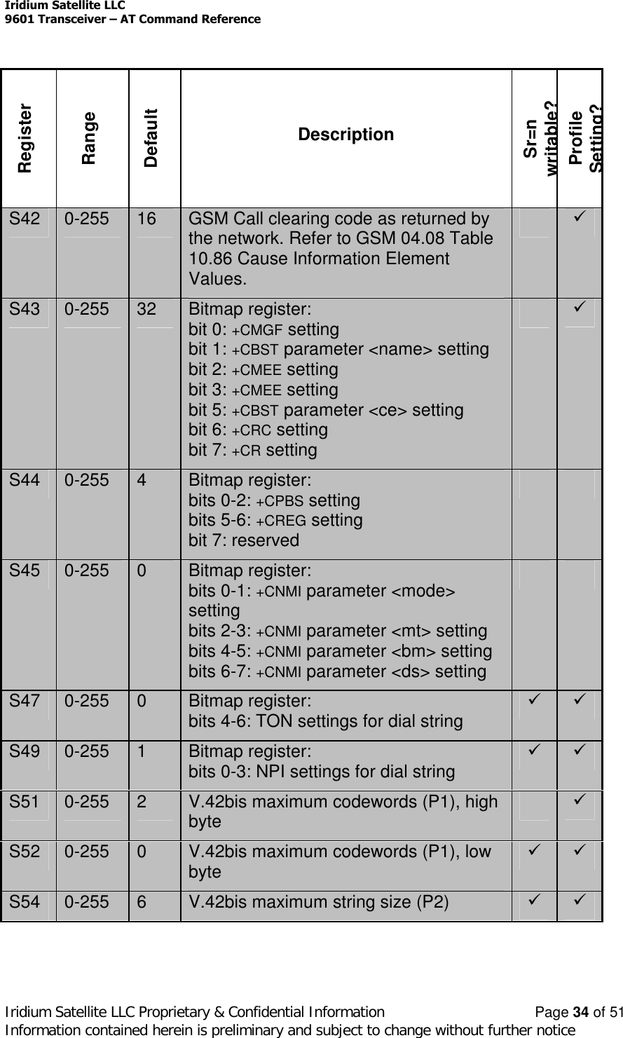
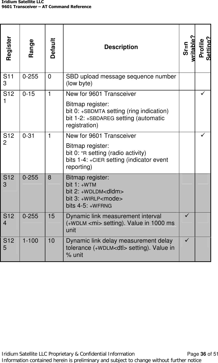
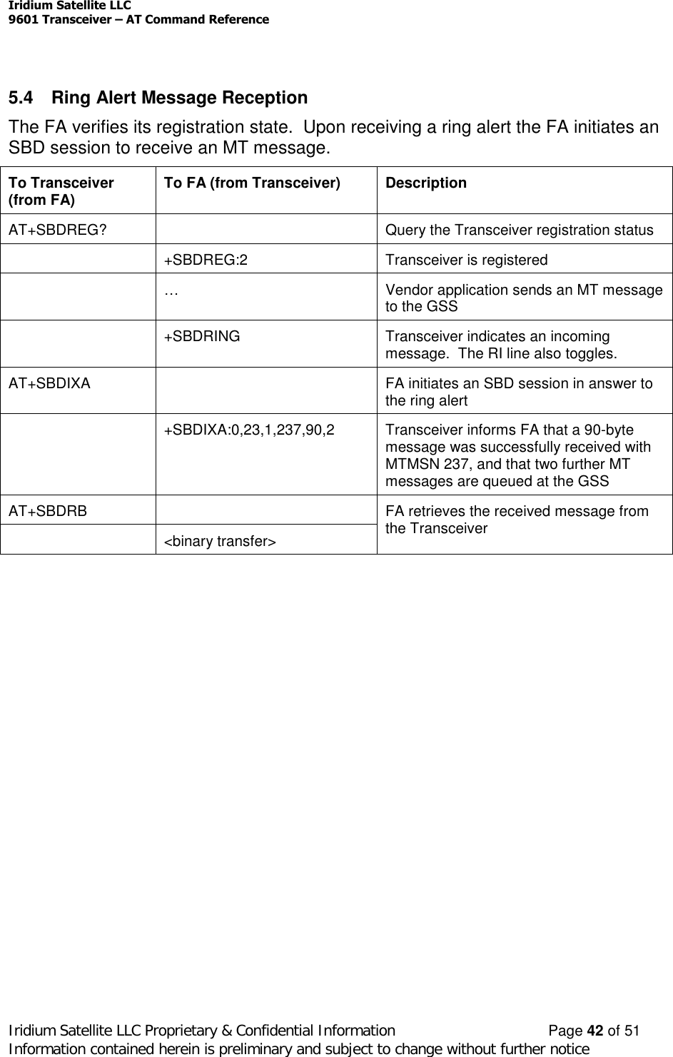
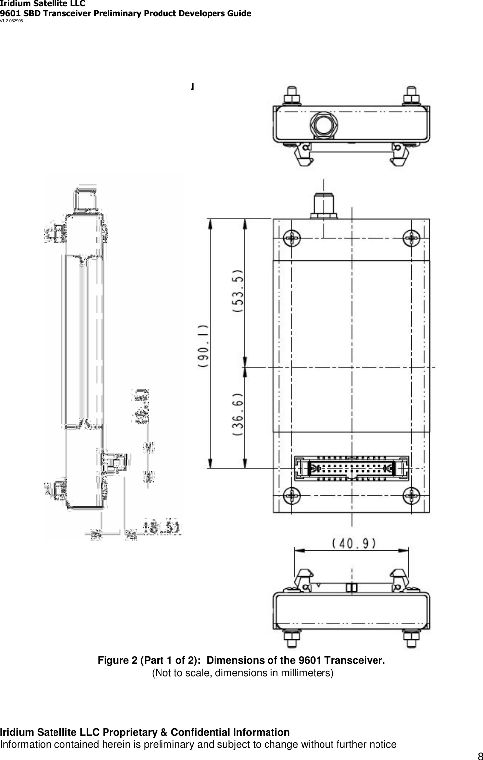
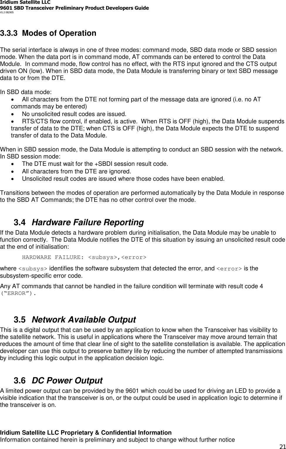
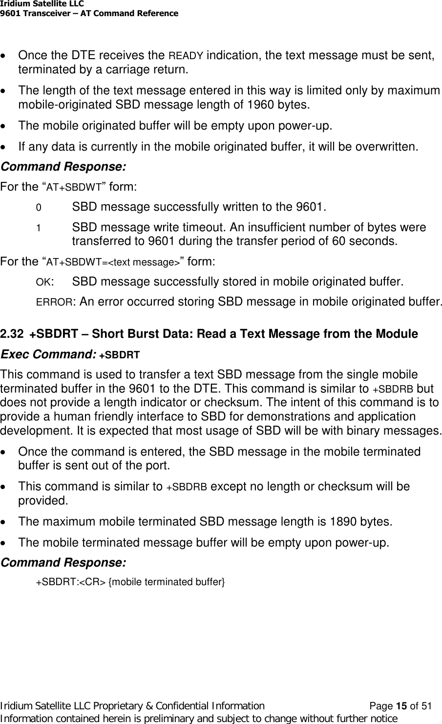
![Iridium Satellite LLC9601 Transceiver –AT Command ReferenceIridium Satellite LLC Proprietary & Confidential Information Page 14 of 51Information contained herein is preliminary and subject to change without further noticeThis command is used to transfer a binary SBD message from the single mobileterminated buffer in the 9601 to the DTE. The mobile terminated buffer can containonly one message at any one time.The SBD message is transferred formatted as follows:{2-byte message length} + {binary SBD message} + {2-byte checksum}The {2-byte message length} field represents the length, in bytes, of theSBD message not including the length field or the mandatory two-bytechecksum. The high order byte will be sent first.The maximum mobile terminated SBD message length is length is specifiedat 135 bytes (and may be increased following actual performance testing).The checksum is the least significant 2-bytes of the summation of the entireSBD message. The high order byte will be sent first. For example if the9601 were to send the word “hello” encoded in ASCII to the DTE the binary stream would be hex 00 05 68 65 6c 6c 6f 02 14.If there is no mobile terminated SBD message waiting to be retrieved fromthe 9601, the message length and checksum fields will be zero.The mobile terminated message buffer will be empty upon power-up.Command Response:There are no response codes generated by the 9601 for this command.2.31 +SBDWT –Short Burst Data: Write a Text Message to the ModuleExec Command: +SBDWT[=<text message>]This command is used to transfer a text SBD message from the DTE to the singlemobile originated buffer in the 9601.The text message may be entered on the command line:For example, “AT+SBDWT=hello”.The length of <text message> is limited to 120 characters. This is due to thelength limit on the AT command line interface.The message is terminated when a carriage return is entered.Alternatively, the text message may entered separately:Upon entering the command “AT+SBDWT”, the 9601 will indicate to the DTE thatit is prepared to receive the message by sending the string “READY<CR><LF>” (hex 52 45 41 44 59 0D 0A) to the DTE.](https://usermanual.wiki/Iridium-Satellite/9601/User-Guide-601743-Page-38.png)
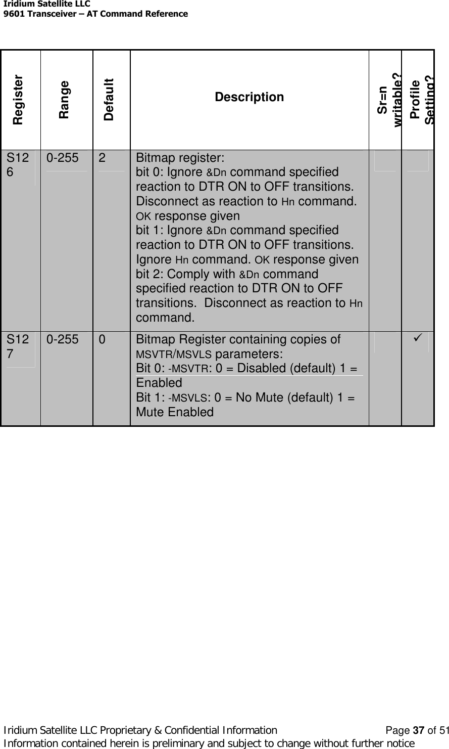
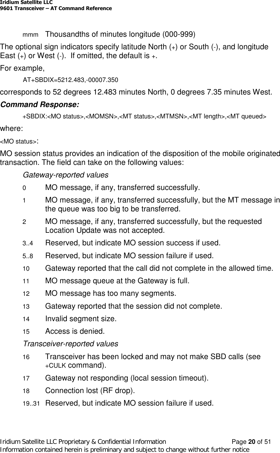
![Iridium Satellite LLC9601 Transceiver –AT Command ReferenceIridium Satellite LLC Proprietary & Confidential Information Page 19 of 51Information contained herein is preliminary and subject to change without further notice0x40 Leave MT message in queue after delivery0x20 Destination in MO payloadRead Command: +SBDDSC?Query the current Delivery Short Code. The response is of the form:+SBDDSC:<dsc>2.36 +SBDIX –Short Burst Data: Initiate an SBD Session Extended (new)Note: The +SBDIX command must be used in place of the +SBDI command for FAswishing to make use of SBD Ring Alert functionality.Exec Command: +SBDIX[A][=<location>]This command initiates an SBD session between the 9601 and the GSS, settingthe SBD Session Type according to the type of command +SBDIX or +SBDIXA,Delivery Short Code according to the value specified by the +SBDDSC command,and the type of location according to whether the optional location value isprovided. If there is a message in the mobile originated buffer it will be transferredto the GSS. Similarly if there is one or more messages queued at the GSS theoldest will be transferred to the 9601 and placed into the mobile terminated buffer.The message, if any, in the mobile originated buffer will be sent from the 9601to the GSS.If there is a message queued at the GSS it will be transferred to the 9601 andplaced into the mobile terminated buffer.This command will always attempt an SBD registration, consisting of attach andlocation update, during the SBD session in order to support SBD Ring Alert. Ifthis is not desired, the +SBDI command should be used.The FA should append an ‘A’ to the command, i.e. +SBDIXA, when the SBDsession is in response to a ring alert.<location> has format:[+|-]DDMM.MMM,[+|-]dddmm.mmmwhere:DD Degrees latitude (00-89)MM Minutes latitude (00-59)MMM Thousandths of minutes latitude (000-999)ddd Degrees longitude (000-179)mm Minutes longitude (00-59)](https://usermanual.wiki/Iridium-Satellite/9601/User-Guide-601743-Page-43.png)
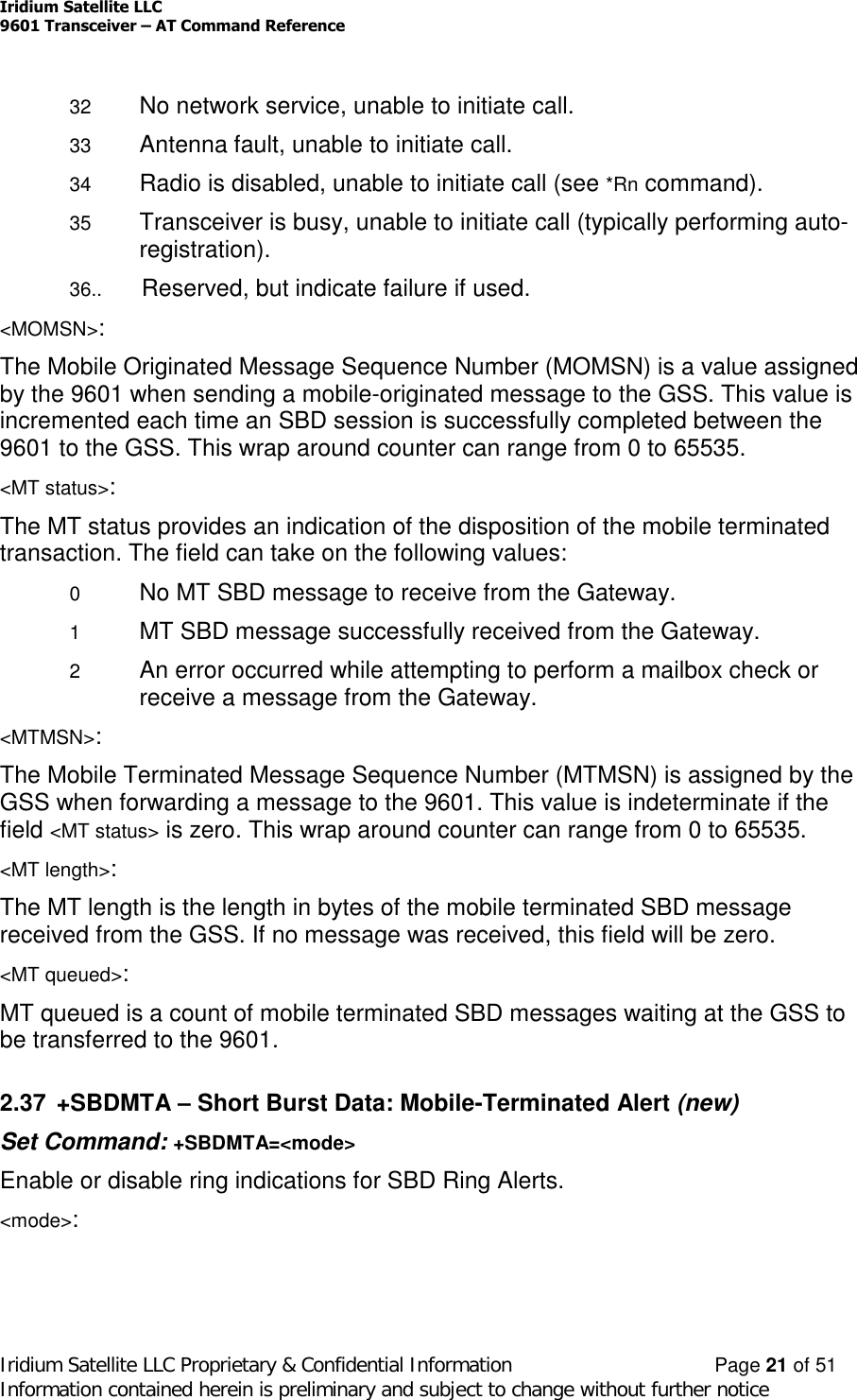
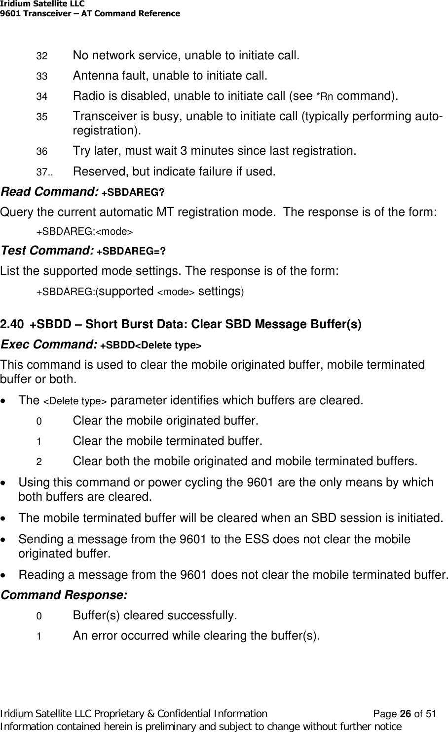
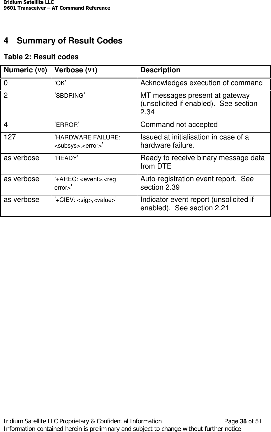
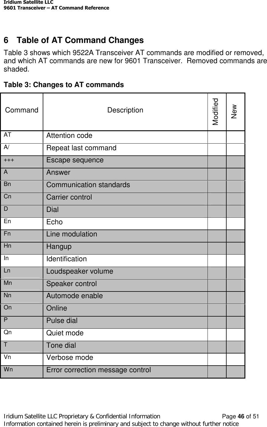
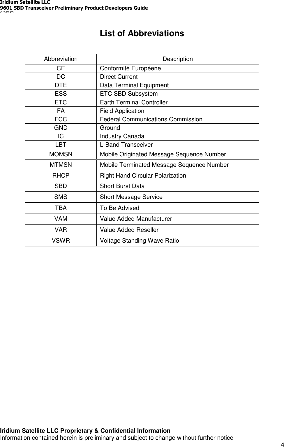
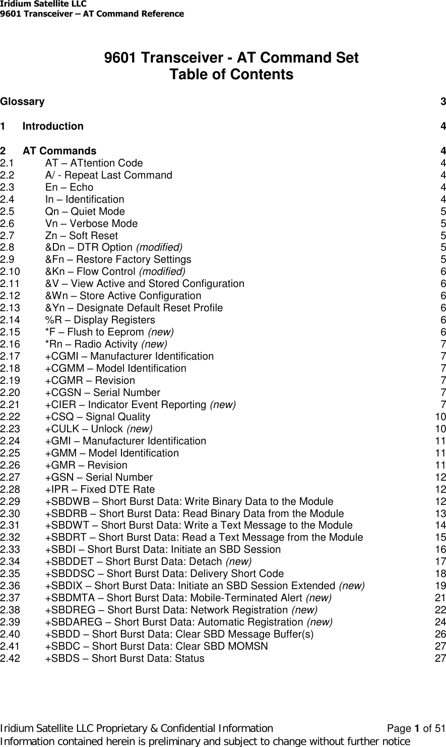
![Iridium Satellite LLC9601 Transceiver –AT Command ReferenceIridium Satellite LLC Proprietary & Confidential Information Page 22 of 51Information contained herein is preliminary and subject to change without further notice0Disable ring indication1Enable ring indication (default)When ring indication is enabled, the 9601 asserts the RI line and issues theunsolicited result code SBDRING when an SBD ring alert is received.Read Command: +SBDMTA?Query the current ring indication mode. The response is of the form:+SBDMTA:<mode>Test Command: +SBDMTA=?List the supported mode settings. The response is of the form:+SBDMTA:(supported <mode> settings)2.38 +SBDREG –Short Burst Data: Network Registration (new)Exec Command: +SBDREG[=<location>]Triggers an SBD session to perform a manual SBD registration.This command initiates an SBD session to perform a manual SBD registration,consisting of an attach and location update. The session type will be set to 2 –registration. This session does not transfer any MO or MT messages.Note: The Transceiver restricts the number of manual and automatic registrationsto one every 3 minutes. Successive attempts within 3 minutes will return an errorcode indicating that the FA should try later (see error 36 below).Note: A user can send an MO SBD message and register at the same time byusing the +SBDIX command. The +SBDIX command always performs a registrationattempt and should be used for an application requiring SBD Ring Alert. The +SBDIcommand never includes an SBD registration and should be used for anapplication that does not require SBD Ring Alert.<location> has format:[+|-]DDMM.MMM,[+|-]dddmm.mmmwhere:DD Degrees latitude (00-89)MM Minutes latitude (00-59)MMM Thousandths of minutes latitude (000-999)ddd Degrees longitude (000-179)mm Minutes longitude (00-59)](https://usermanual.wiki/Iridium-Satellite/9601/User-Guide-601743-Page-46.png)