Iridium Satellite 9601 Satellite SBD Transceiver module type 9601 User Manual
Iridium Satellite LLC Satellite SBD Transceiver module type 9601
User manual
9601 Short Burst Data Onl y Transceiver
Preliminary Product Developers Guide
R ev i s io n 1 .2
Au gus t 28 t h 2005
Iridium Satellite LLC Proprietary & Confidential Information
Iridium Satellite LLC
6701 Democracy Blvd., Suite 500
Bethesda, MD 20817 USA
www.iridium.com
Toll Free: +1.866.947.4348 [US Only]
International +1.480.752.5155
email: info@iridium.com

Iridium Satellite LLC
9601 SBD Transceiver Preliminary Product Developers Guide
V1.2 082905
Iridium Satellite LLC Proprietary & Confidential Information
Information contained herein is preliminary and subject to change without further notice
2
Preliminary Product Information Purpose & Disclaimer
This document contains preliminary product information for the new Iridium 9601 Short Burst
Data Transceiver. The purpose of providing this information is to enable Value Added Resellers
and Value Added Manufacturers to begin to understand the product and how to integrate it into a
complete wireless data solution.
By providing the information contained herein, Iridium Satellite LLC makes no guarantee or
warranty, and does not assume liability with respect to the accuracy or the completeness of such
information, or to the results of use of the planned product in any specific instance, and hereby
expressly disclaims any implied warranties of merchantability or fitness for a particular purpose,
or any other warranties or representations whatsoever, expressed or implied.
Iridium Satellite LLC reserves the right to modify or change specifications, detailed herein, at any
time without notice.
Export Compliance Information
This product is controlled by the export laws and regulations of the United States of America. The U.S.
Government may restrict the export or re-export of this product to certain individuals and/or destinations.
For further information, contact the U.S. Department of Commerce, Bureau of Industry and Security or
visit www.bis.doc.gov.
Revision History
Revision Date Comment
V1.0 May 02 2005 First revision
V1.2 Aug 28 2005
Second revision incorporating major updates. Key updates are:
Product name change to “9601 SBD Transceiver”
Physical packaging
Connector types updated
AT Commands added and updated

Iridium Satellite LLC
9601 SBD Transceiver Preliminary Product Developers Guide
V1.2 082905
Iridium Satellite LLC Proprietary & Confidential Information
Information contained herein is preliminary and subject to change without further notice
3
Contents
Preliminary Product Information Purpose & Disclaimer ............................................................................... 2
Revision History............................................................................................................................................ 2
List of Abbreviations ..................................................................................................................................... 4
1.0 Product Overview .................................................................................................................. 5
1.1 Key Features ......................................................................................................................... 5
1.2 Transceiver Packaging and Regulatory Certification ............................................................ 6
2.0 Physical Specifications.......................................................................................................... 7
2.1 Dimensions............................................................................................................................ 7
2.2 Mechanical Dimensions –Mounting...................................................................................... 9
2.2.1 Mounting - Stackable Design............................................................................................... 10
2.2.2 Mounting to a Panel/Surface –For use with cable connections ......................................... 12
2.3 Environmental...................................................................................................................... 14
2.4 Interface Connectors ........................................................................................................... 14
3.0 Electrical Interfaces ............................................................................................................. 15
3.1 Multi-Interface Connector .................................................................................................... 15
3.1.1 Connector Type ................................................................................................................... 15
3.1.2 Connector Pin Allocation ..................................................................................................... 16
3.2 DC Power Interface ............................................................................................................. 18
3.2.1 Power On/Off Control .......................................................................................................... 18
3.3 Serial Data Interface............................................................................................................ 19
3.3.1 9-Wire and 3-Wire Operation............................................................................................... 19
3.3.2 Configuration Settings ......................................................................................................... 20
3.3.3 Modes of Operation ............................................................................................................. 21
3.4 Hardware Failure Reporting ................................................................................................ 21
3.5 Network Available Output.................................................................................................... 21
3.6 DC Power Output ................................................................................................................ 21
4.0 RF Interface......................................................................................................................... 22
4.1 Antenna Connector.............................................................................................................. 22
4.1.1 Antenna Connector Type..................................................................................................... 22
4.2 R F Interface Specifications ........................................................................................ 23
4.3 Radio Characteristics ..................................................................................................... 23
5.0 Modem Commands and Configuration................................................................................ 24

Iridium Satellite LLC
9601 SBD Transceiver Preliminary Product Developers Guide
V1.2 082905
Iridium Satellite LLC Proprietary & Confidential Information
Information contained herein is preliminary and subject to change without further notice
4
List of Abbreviations
Abbreviation Description
CE Conformité Européene
DC Direct Current
DTE Data Terminal Equipment
ESS ETC SBD Subsystem
ETC Earth Terminal Controller
FA Field Application
FCC Federal Communications Commission
GND Ground
IC Industry Canada
LBT L-Band Transceiver
MOMSN Mobile Originated Message Sequence Number
MTMSN Mobile Terminated Message Sequence Number
RHCP Right Hand Circular Polarization
SBD Short Burst Data
SMS Short Message Service
TBA To Be Advised
VAM Value Added Manufacturer
VAR Value Added Reseller
VSWR Voltage Standing Wave Ratio

Iridium Satellite LLC
9601 SBD Transceiver Preliminary Product Developers Guide
V1.2 082905
Iridium Satellite LLC Proprietary & Confidential Information
Information contained herein is preliminary and subject to change without further notice
5
1.0 Product Overview
The Iridium 9601 Short Burst Data Only Transceiver (9601) is designed to be integrated into a wireless
data application with other hardware and software to produce a full solution designed for a specific
application or vertical market. Examples of these solutions include a tracking a maritime vessel or automatic
vehicle location.
The 9601 only supports Iridium’s Short Burst Data (SBD) capability. It does not support voice, circuit
switched data, or short message service (SMS). This is a new product and has no functional
predecessor.
The 9601 will be designed to meet the regulatory requirements for approval for FCC, Canada, and CE
assuming an antenna with a gain of ~3 dBi and adequate shielding. This allows the 9601 to be integrated
into a variety of wireless data applications or retrofitted into existing SBD only applications that utilize SBD
with the current Iridium 9522A or 9522 L-Band Transceiver-based product. (Note that additional
development work will be required.) Such finished products, when integrated together, require regulatory
testing to be conducted by the integrator.
The 9601 is designed as a single board transceiver and is essentially provided as a ‘black box’
transceiver with all device interfaces provided by a single multi-pin interface connector in addition to the
antenna connector. The product only provides the core transceiver. All other end user application functions
such as GPS, microprocessor based logic control, digital and analog inputs, digital and analog outputs
power supply and antenna must be provided by the solution developer. The device interface consists of the
serial interface, power input, network available output and power on/off control line.
The 9601 does not incorporate nor require a Subscriber Identity Module (also know as a SIM Card) to be
inserted into the transceiver. The 9601 will be designed to comply with the standards for Radio Emissions
Compliance, Electromagnetic Compatibility, and AC Safety in the United States, European Union and
Canada.
The 9601 is described within this document as “9601”, “9601 Transceiver”and “9601 SBD Transceiver”
all of these terms refer to the same product.
1.1 Key Features
Single board transceiver
Small form factor
No SIM card
Designed to be incorporated into an OEM solution
Maximum mobile originated message size 205 bytes (subject to revision)
Maximum mobile terminated message size 135 bytes (subject to revision)
Uses small omni-directional antenna
Global operating capability

Iridium Satellite LLC
9601 SBD Transceiver Preliminary Product Developers Guide
V1.2 082905
Iridium Satellite LLC Proprietary & Confidential Information
Information contained herein is preliminary and subject to change without further notice
6
1.2 Transceiver Packaging and Regulatory Certification
The 9601 Transceiver is a regulatory approved transceiver that is provided in an enclosure and with
appropriate connectors that permit the full transceiver to be regulatory tested by Iridium and sold as a
Regulatory Certified product that meets CE, FCC and IC requirements.
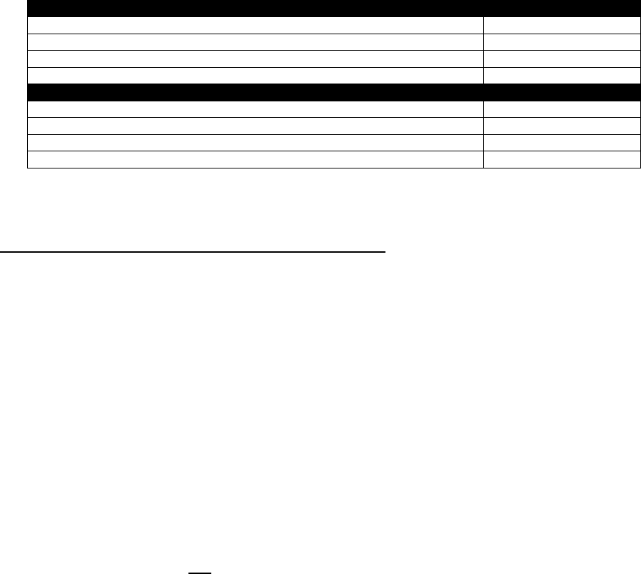
The 9601 is tested to the regulatory and technical certifications shown in Table 1.
Table 1: Regulatory and Technical Certifications.
Regulatory
Approvals Radio Tests EMC Tests
Electrical /
Mechanical /
Operational
Safety Tests
CE
FCC
Industry
Canada
ETSI EN 301 441
V1.1.1 (200005)
FCC parts 2, 15, and 25
Industry Canada
RSS170 Issue 1, Rev 1,
November 6, 1999
ETSI EN 301 4891 V1.4.1 (200208)
ETSI EN 301 48920
V1.2.1(200211)
EN6100042 : 1995 / A2 : 2001
EN6100043 : 2002
EN6100044 : 2004
EN6100046 : 1996 / A1 : 2001
EN55022:1998/A1:200
0/A2:2003
(see clause 8.3 of ETSI EN301
4891 V1.4.1)
EN609501:2001 Part 1
Iridium Satellite LLC
9601 SBD Transceiver Preliminary Product Developers Guide
V1.2 082905
Iridium Satellite LLC Proprietary & Confidential Information
Information contained herein is preliminary and subject to change without further notice
7
2.0 Physical Specifications
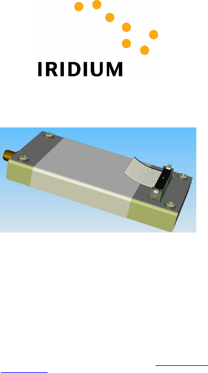
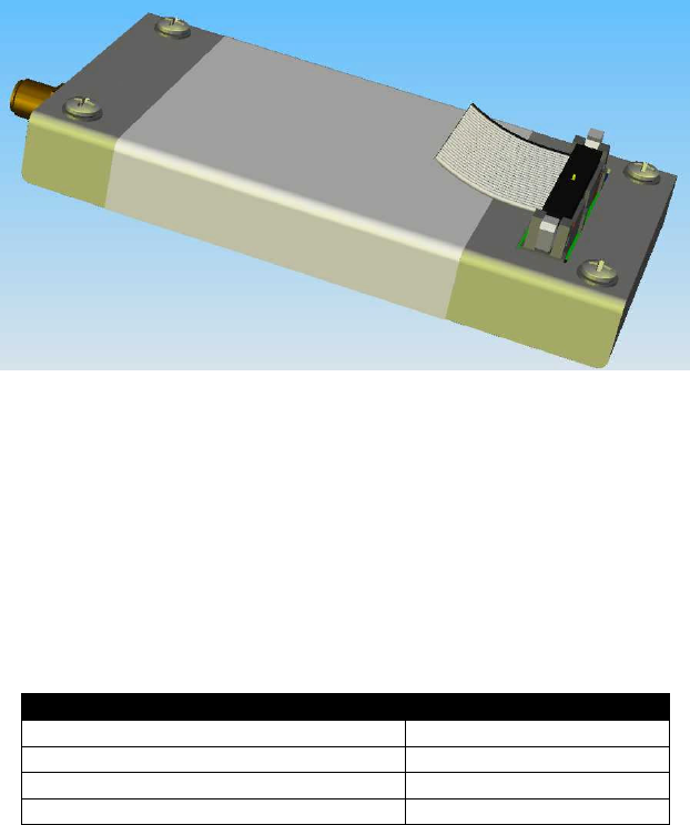
For illustrative purposes a rendering of the 9601 ISU is shown in Figure 1 with a ribbon cable connector
inserted. (Note that the ribbon cable and connector is to be provided by the developer and is not supplied
as part of the commercial product.)
Figure 1: The 9601 Transceiver.
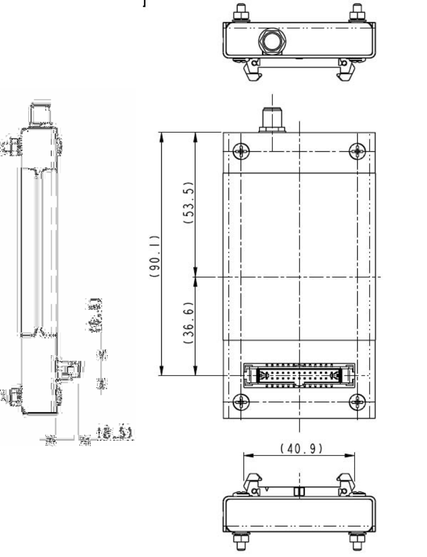
2.1 Dimensions
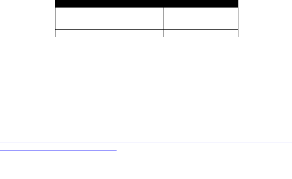
The overall dimensions of the 9601 and its weight are summarized in Table 2 and represented graphically
in third angle projection in Figure 2
Table 2: 9601 Mechanical Dimensions
Parameter Value
Length 106 mm
Width 56.2 mm
Depth 13 mm
Weight (approximate) TBA
Note that these dimensions are for the enclosure and do not take into account the connectors or mounting
hardware. Additionally developers should plan for additional space for the reciprocal connectors for the
antenna and user connector.
Iridium Satellite LLC
9601 SBD Transceiver Preliminary Product Developers Guide
V1.2 082905
Iridium Satellite LLC Proprietary & Confidential Information
Information contained herein is preliminary and subject to change without further notice
8
Figure 2 (Part 1 of 2): Dimensions of the 9601 Transceiver.
(Not to scale, dimensions in millimeters)

Iridium Satellite LLC
9601 SBD Transceiver Preliminary Product Developers Guide
V1.2 082905
Iridium Satellite LLC Proprietary & Confidential Information
Information contained herein is preliminary and subject to change without further notice
9
Figure 2 (Part 2 of 2): Dimensions of the 9601 Transceiver.
(Not to scale, dimensions in millimeters)
2.2 Mechanical Dimensions –Mounting
The 9601 Transceiver is provided with four mounting holes, one at each corner. During manufacture four
screws are inserted for shipping purposes. These screws need to be removed for mounting. There are
two basic options for mounting –stackable and mounting to a surface such as a mounting plate or
enclosure wall. The following sections provide further information.
Iridium Satellite LLC
9601 SBD Transceiver Preliminary Product Developers Guide
V1.2 082905
Iridium Satellite LLC Proprietary & Confidential Information
Information contained herein is preliminary and subject to change without further notice
10
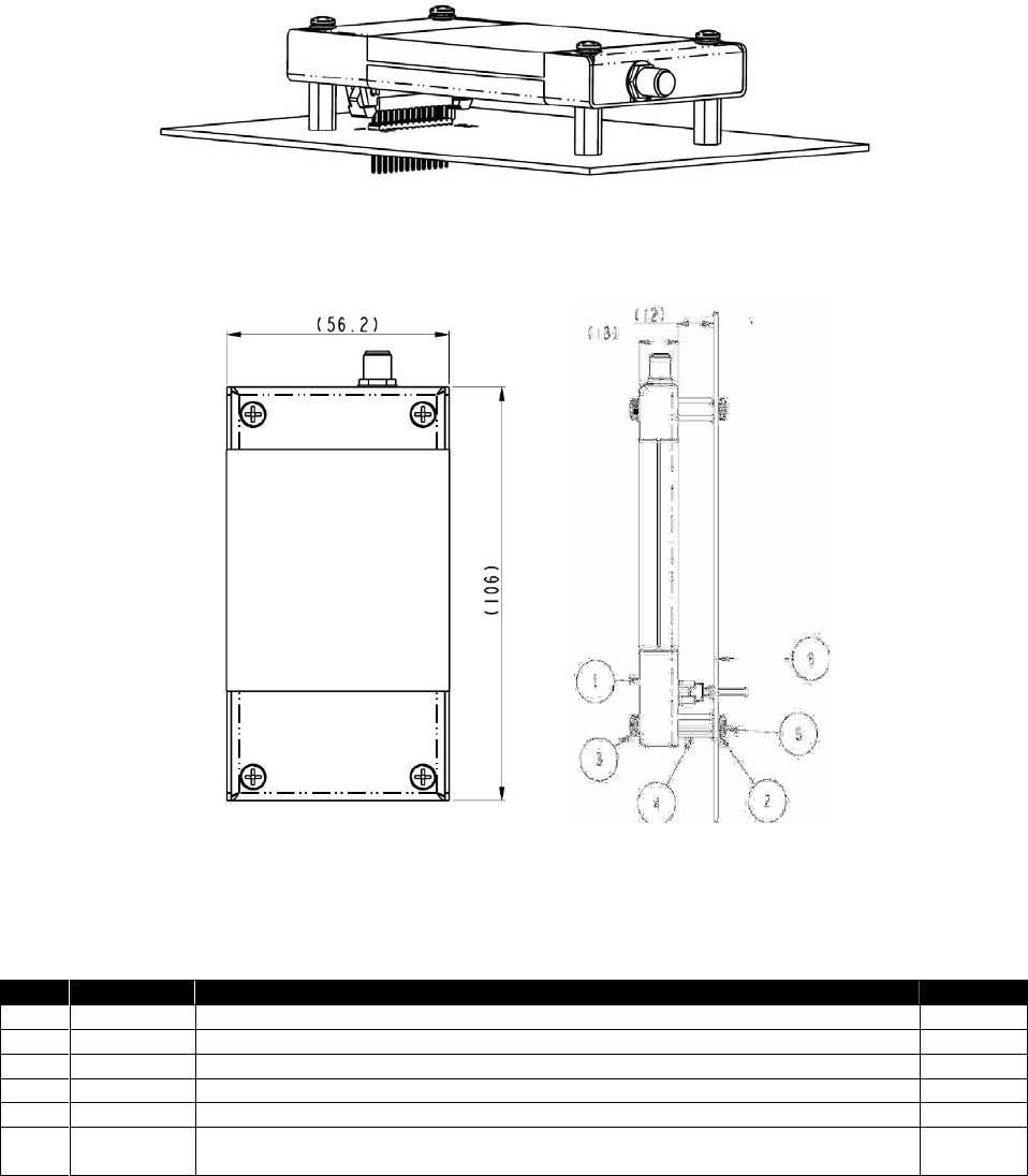
2.2.1 Mounting - Stackable Design
An example stackable design is shown in Figure 3.
Figure 3: 9601 Transceiver mounted to a unpopulated PCB.
The figures and tables below provides mechanical information design information for a suitable
‘stackable’ 9601 to developer PCB configuration
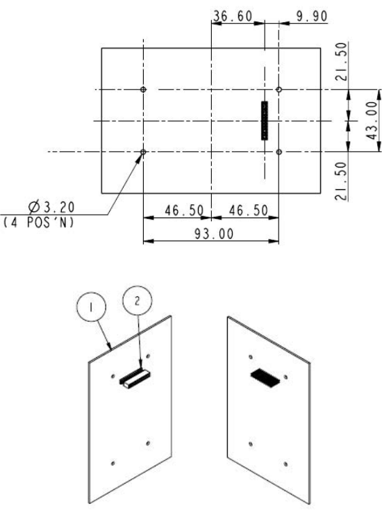
Figure 4: Assembly Item Number Identification.
Item Numbers in Figure 4 are described in Table 3. Not to scale. Dimensions in millimeters.
Table 3: Item Number Description for Figure 4
Item Type Description Quantity
1 Assembly 9601 Transceiver 1
2 Part M3 Shake-proof washer, zinc plated steel [4 supplied with item 1] 8
3 Part M3 x 20 Pan head screw, pozidrive, zinc plated steel [4 supplied with item 1] 4
4 Part M3 Threaded standoff, 6.0 A/F HEX x 12.00 mm 4
5 Part M3 x 8 Pan head screw, pozidrive, zinc plated steel 4
6 Assembly Solution developer PCB fitted with Samtec connector ESQT-113-02-L-D-425.
[This item is the same item as Item 1 in Figure 5.] 1
Iridium Satellite LLC
9601 SBD Transceiver Preliminary Product Developers Guide
V1.2 082905
Iridium Satellite LLC Proprietary & Confidential Information
Information contained herein is preliminary and subject to change without further notice
11
Figure 5: Mechanical mounting foot print for use when stacking the 9601 with a developer
provided PCB. (Dimensions in milli-meters, not to scale)
Notes for Figure 5:
1. Item 1 is a generic, developer provided PCB design and shown for illustrative purposes. This item is
the same as Item 6 in Figure 4.
2. Item 2 is available from Samtec in a variety of heights. This example shows a 0.425" version. The
part number for this connector is ESQT-113-02-L-D-425
3. Compatible heights of stand-offs and variants on Item 2 are as follows:
a. 0.425" height (shown) fits with 12mm high spacers
b. 0.327" height is minimum that can be used. Fits with 9.50mm spacers.
c. 0.800" height is the maximum height available fits with 21.50mm spacers.
d. Anything else in-between should work if 'Samtec height' = 'Spacer height' minus 1.20mm.
4. Suggested examples of spacer types and compatible fasteners:
a. M3 threaded thru' hole 6.0 A/F Hex x 12mm, re-use M3 x 20 shipping screws and
washers, add M3 x 8 screws and washers.
b. Plain thru' hole diameter 3.2-3.5, diameter 6.0 x 9.50mm, replace M3 x 20 shipping
screws with M3 x 30 screws (same nuts and washers.)
c. Plain thru' hole diameter 3.2-3.5, diameter 6.0 x 21.50mm, replace M3 x 20 shipping
screws with M3 x 35 screws (same nuts and washers.)
Iridium Satellite LLC
9601 SBD Transceiver Preliminary Product Developers Guide
V1.2 082905
Iridium Satellite LLC Proprietary & Confidential Information
Information contained herein is preliminary and subject to change without further notice
12
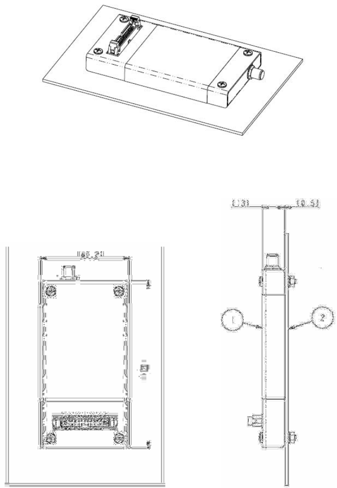
2.2.2 Mounting to a Panel/Surface –For use with cable connections
An example of mounting to a panel or other surface design is shown in Figure 6.
Figure 6: 9601 Transceiver mounted to a plate or surface.
The figures and tables below provide mechanical information design information for a mounting a 9601 to
a plate or surface configuration
Figure 7: Assembly Item Number Identification.
Item Numbers in Figure 7 are described in Table 4. (Not to scale. Dimensions in millimeters.)
Notes for Figure 7:
1. Item 1 includes 4 off M3 x 20 shipping screws, shake-proof washers and nuts
2. Shipping screws can be used to attach Transceiver to panel of 2.00 mm maximum thickness
3. Panels thicker than 2.00mm require longer screws to be e.g. M3 x 25mm
4. See Figure 8 for mounting hole dimensions
Iridium Satellite LLC
9601 SBD Transceiver Preliminary Product Developers Guide
V1.2 082905
Iridium Satellite LLC Proprietary & Confidential Information
Information contained herein is preliminary and subject to change without further notice
13
Table 4: Item Number Description for Figure 7
Item Type Description Quantity
1 Assembly 9601 Transceiver 1
2 Part Mounting Plate or Surface (developer provided) 1
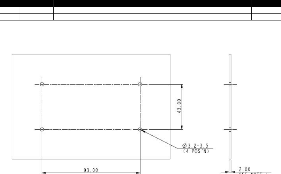
Figure 8: Mechanical mounting foot print for use when panel mounting 9601.
(Dimensions in milli-meters, not to scale)

Iridium Satellite LLC
9601 SBD Transceiver Preliminary Product Developers Guide
V1.2 082905
Iridium Satellite LLC Proprietary & Confidential Information
Information contained herein is preliminary and subject to change without further notice
14
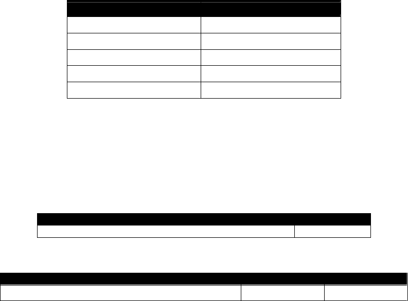
2.3 Environmental
The environmental specifications of the 9601 are summarized in Table 5 below.
Table 5: Environmental Specifications
Parameter Value
Operating Temperature Range -30ºC to + 60ºC
Operating Humidity Range ≤75% RH
Storage Temperature Range -40ºC to + 85ºC
Storage Humidity Range ≤ 93% RH
The 9601 has been tested to the specifications listed in Table 6.
Table 6: Environmental Tests
Test Name Test Reference Test Description
Thermal Shock EN60068-2-14:2000 Change of Temperature,
-25C to +70C,
5 cycles of 1 hour each
Humidity IEC60068-2-3:1969 Damp heat steady state
40C 93% RH for 4 days
Shock EN60068-2-27:1993
(NF c20-727)
Shock J1455 Society of Automotive Engineers
Vibration EN 60068-2-36:1996 Sinusoidal Vibration
0.96 m2/s3 from 5Hz to 20Hz
Vibration IEC 60068-2-36:1996 Sinusoidal Vibration
21Hz to 500Hz
-3dB per octave
Vibration J1455 Society of Automotive Engineers
2.4 Interface Connectors
The 9601 Transceiver incorporates two connectors:
A multi-interface connector
An antenna connector
These interfaces are described in more detail in Sections 3 and 4 respectively.

Iridium Satellite LLC
9601 SBD Transceiver Preliminary Product Developers Guide
V1.2 082905
Iridium Satellite LLC Proprietary & Confidential Information
Information contained herein is preliminary and subject to change without further notice
15
3.0 Electrical Interfaces
The subsections to follow contain information for the electrical interfaces of the 9601 Transceiver.
3.1 Multi-Interface Connector
The multi-interface connector includes six interfaces:
DC power supply input
Power on/off control
RS-232 Serial data
Network available output
DC power output
3.1.1 Connector Type
The connector on the 9601 is a Samtec EHT series. This connector provides the ability for both a cable
connector as well as a stackable board to board connection. For cable connected applications use the
Samtec TCSD series. For PCB stacking use the Samtec ESQT series.
Data sheets on these connectors can be found at:
EHT Series: http://www.samtec.com/technical_specifications/overview.asp?series=EHT
TCSD Series: http://www.samtec.com/technical_specifications/overview.asp?series=tcsd
ESQT Series: http://www.samtec.com/technical_specifications/overview.asp?series=esqt

Iridium Satellite LLC
9601 SBD Transceiver Preliminary Product Developers Guide
V1.2 082905
Iridium Satellite LLC Proprietary & Confidential Information
Information contained herein is preliminary and subject to change without further notice
16
3.1.2 Connector Pin Allocation
The user connector is a 2 row 26-way latching header. Individual pin assignments are shown in Table 7.
Multiple supply grounds are provided and all supply and supply grounds (pins 1-6) are required to be
connected to the power supply in order to limit the current on any one pin. The three Supply Returns (pins
4, 5 & 6) are tied together at the connector as well as the three Supply pins (pins 1, 2 & 3.) Multiple signal
grounds are provided to reduce cross-talk. The signal grounds on pins 10,13, 20 & 23 are all tied together
at the connector and can be joined with any of the signal wires e.g. RS232, Network Available etc.
However each signal requires its own signal ground in order to limit current on any one pin.
Table 7: Multi Interface Connector Pin Allocation
Pin
No. Signal Name Signal
direction
(WRT 9601) Signal function Signal level
1 EXT_PWR Input Supply +5 V +/- 0.5 V
2 EXT_PWR Input Supply +5 V +/- 0.5 V
3 EXT_PWR Input Supply +5 V +/- 0.5 V
4 EXT_GND Supply return 0 V
5 EXT_GND Supply return 0 V
6 EXT_GND Supply return 0 V
7 ON/OFF Input On/Off control input On: 2.0V to Vsupply
Off: 0V to 0.5V
I = 120 μA max
8 Reserved
9 Reserved
10 SIG_GND Signal ground 0V
11 DF_S_TX Input Data port, serial data into data module RS-232
12 DF_S_RX Output Data port, serial data from data module RS-232
13 SIG_GND Signal ground 0V
14 DF_ DCD Output Data port, Data Carrier Detect RS-232
15 DF_ DSR Output Data port, Data Set Ready RS-232
16 DF_ CTS Output Data port, Clear-to-Send RS-232
17 DF_RI Output Data port, Ring Indicator RS-232
18 DF_ RTS Input Data port, Request-to-Send RS-232
19 DF_ DTR Input Data port, Data Terminal Ready RS-232
20 SIG_GND Signal ground 0V
21 Reserved
22 Reserved
23 SIG_GND Signal ground 0V
24 NETWORK_
AVAILABLE Output Set to logic 1 when network is visible 2.9 V CMOS
25 Spare
26 +2V9 Output Supply output +2.9 V ± 0.15 V,
50mA maximum
Iridium Satellite LLC
9601 SBD Transceiver Preliminary Product Developers Guide
V1.2 082905
Iridium Satellite LLC Proprietary & Confidential Information
Information contained herein is preliminary and subject to change without further notice
17
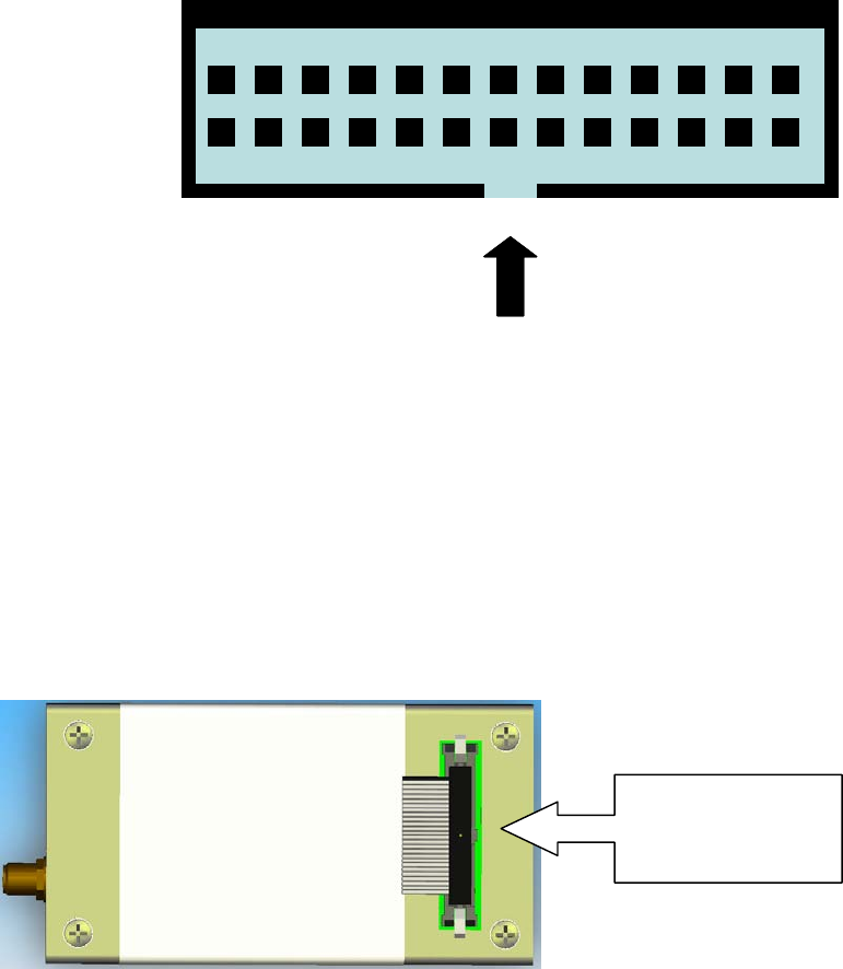
Figure 9 provides a reference for the pin designation. Note that this designation is when looking into the
multi-interface connector from above. It is not to scale and not representative of the actual connector
mechanical layout.
01 03
02
Connector notch
26
2501 03
02
Connector notch
26
25
Figure 9: Multi-Interface Connector Pin Number Designation
Notes:
1. View looking into connector from above
2. Numbers indicate pin designations
3. Not to scale, for illustrative purposes only
4. Note location of connector notch
5. Connector notch faces towards opposite end to the antenna connector as shown in Figure 10
6. On the physical connector Pin 1 is indicated by an arrow mark
Figure 10: Multi Interface Connector Notch Location
Notch on
connector is on this
side
Iridium Satellite LLC
9601 SBD Transceiver Preliminary Product Developers Guide
V1.2 082905
Iridium Satellite LLC Proprietary & Confidential Information
Information contained herein is preliminary and subject to change without further notice
18
3.2 DC Power Interface
The DC power interface is comprised of the DC power inputs and a control signals as summarized in
Table 7. The three +5V Inputs and three 0V supply returns are used to supply DC power to the 9601 and
ensure that enough current can be drawn across the connector without the 9601 malfunctioning during
transmit due to lack of current supply. Note that all six pins should be connected.
The DC power supply requirements for the 9601 are summarized in Table 8 below. Note that these
requirements apply to DC power measured at the 9601 multi-interface connector input and not at the
output of the power supply. Long power supply cables can cause a voltage drop sufficient to cause the
voltage to be out of specification at the physical power supply input to the 9601.
Table 8: DC Power Input Specifications
Parameter Value
Main Input Voltage Range +4.5 VDC to +5.5 VDC
Main Input Voltage Nominal 5.0VDC
Main Input Voltage –Ripple 40 mV pp
Consumption at +5.0 VDC Value
Input Standby Current (average) 100mA
Peak Transient Current –Transmit <= 2.0A
Current Average –when SBD message transfer in process <= 350 mA
Average Power consumption –when SBD message transfer in process <= 1.75 W
Note: The average power consumption depends on the view of the satellite constellation from the
antenna.
The external power supply needs to guarantee the following:
The supply voltage droop over an 8.3mS burst should not be more than 0.2 Volts.
The power supply should limit the in-rush current to 4 Amps maximum
The supply noise should be less than that in the following profile (linear interpolation between these
points):
100 mV pk-pk 0Hz to 50 kHz
5 mV pk-pk in 50 kHz bandwidth at 1 MHz
10 mV pk-pk in 1 MHz bandwidth at 1 MHz
5 mV pk-pk in 1 MHz bandwidth above 5 MHz.
3.2.1 Power On/Off Control
An external on/off input is provided on a pin of the multi-interface connector. The 9601 starts up when
power is applied and the power on/off input is high. As long as the input voltage is applied, logic high on
this line turns the transceiver on and a logic low turns it off. If this line is not required then it must be
connected directly to the +5 V supply. The input logic high threshold is 2.0 V and the logic low threshold is
0.5 V.
Note that this on/off control is not the same as the 9522 or 9522A.

Iridium Satellite LLC
9601 SBD Transceiver Preliminary Product Developers Guide
V1.2 082905
Iridium Satellite LLC Proprietary & Confidential Information
Information contained herein is preliminary and subject to change without further notice
19
3.3 Serial Data Interface
The Serial data interface is used to both command the 9601 and transfer user data to and from the
Transceiver. The 9601 presents a 9-wire data port to the FA (Field Application), where the interface is at
RS232 levels. With respect to this interface, the Data Module behaves as a DCE (Data Communication
Equipment), and the FA behaves as a DTE (Data Terminal Equipment).
The terms “FA” and “DTE” are used interchangeably throughout this document; similarly for the terms
“Data Module” and “DCE”.
Autobaud is not supported in 9601 Transceiver. The baud rate can be set via the AT+IPR command. The
default rate is 19200 bps.
3.3.1 9-Wire and 3-Wire Operation
By default, the serial interface operates as a 9-wire connection. Table 9 describes each of the signals,
where “input” means an input to the Data Module, and “output” means an output from the 9601
Transceiver.
Table 9 –Serial Interface Signals
Signal Description
RX Active high data input
TX Active high data output
GND 0V
RTS Active low flow control input
CTS
Active low flow control output
RTS and CTS are used together to implement hardware flow control when enabled with
AT&K3
DTR
Active low handshaking input
AT&Dn controls how the Data Module uses DTR:
If set to AT&D0, DTR is always ignored.
Otherwise DTR set to OFF places the data port into UART test mode after 10
seconds, or immediately on boot-up. A subsequent transition of DTR to ON returns
the data port to DCE mode and resets it to its power-on state.
The UART test mode is provided for factory testing of the data port UART. An FA
should never activate test mode; if it does, the Data Module will stop responding to
AT commands until the data port is returned to DCE mode.
DSR
Active low handshaking output
The Data Module drives DSR ON when the data port is in DCE mode, and OFF when
the data port is in test mode.
The DTE may use this signal as an indication that the Data Module is powered up and
ready to receive AT commands.
RI
Active low ring indicator output
The Data Module drives RI ON when it receives a ring alert from the network, and drives
RI OFF after 5 seconds or when the DTE initiates an SBD session, whichever occurs
first.
DCD Active low handshaking output
DCD is driven ON at all times.
Iridium Satellite LLC
9601 SBD Transceiver Preliminary Product Developers Guide
V1.2 082905
Iridium Satellite LLC Proprietary & Confidential Information
Information contained herein is preliminary and subject to change without further notice
20
Note that the Ring Indicator (RI) pin is used by the 9601 Transceiver to indicate that a Mobile Terminated
SBD (MT-SBD) message is queued at the Gateway. The Field Application will need to monitor this pin
and use appropriate AT Commands to command the Transceiver to retrieve the MT-SBD message.
The serial interface may be operated with a 3-wire connection, where only transmit, receive and ground
signals are used. However the 9 wire interface offers better control and is the recommended
implementation. Iridium is only able to provide limited 3-wire interface support. When operating with a 3-
wire connection, the following rules apply:
AT&Dn must be set to AT&D0 to ignore the DTR input
AT&Kn must be set to AT&K0 to disable RTS/CTS flow control
The other output signals may be connected, and operate as follows:
CTS driven ON (low)
DSR operates as normal
RI operates as normal
DCD driven ON (low)
Note: RTS/CTS flow control, when enabled, is only used when the data port is in SBD data mode. In AT
command mode, RTS is ignored and CTS is driven ON (low).
3.3.2 Configuration Settings
The Data Module allows the DTE to configure the data port communication parameters. The three
configuration types are active, factory default, and stored. The active configuration is the set of
parameters currently in use. They can be changed by the DTE individually via specific AT commands.
The factory default configuration is stored in permanent memory. This configuration can be recalled at
any time through use of the AT&Fn command.
Two groups of settings, or “profiles”, can be stored as user-defined configurations. The DTE first creates
desired active configurations and then writes them to memory using the AT&Wn command. These
profiles can be designated to be loaded as the active configuration upon Data Module power-up through
use of the AT&Yn command. The Data Module can be reset without loss of power to these profiles
through use of the ATZn command.
The configuration settings are stored in “S-register” locations.
Iridium Satellite LLC
9601 SBD Transceiver Preliminary Product Developers Guide
V1.2 082905
Iridium Satellite LLC Proprietary & Confidential Information
Information contained herein is preliminary and subject to change without further notice
21
3.3.3 Modes of Operation
The serial interface is always in one of three modes: command mode, SBD data mode or SBD session
mode. When the data port is in command mode, AT commands can be entered to control the Data
Module. In command mode, flow control has no effect, with the RTS input ignored and the CTS output
driven ON (low). When in SBD data mode, the Data Module is transferring binary or text SBD message
data to or from the DTE.
In SBD data mode:
All characters from the DTE not forming part of the message data are ignored (i.e. no AT
commands may be entered)
No unsolicited result codes are issued.
RTS/CTS flow control, if enabled, is active. When RTS is OFF (high), the Data Module suspends
transfer of data to the DTE; when CTS is OFF (high), the Data Module expects the DTE to suspend
transfer of data to the Data Module.
When in SBD session mode, the Data Module is attempting to conduct an SBD session with the network.
In SBD session mode:
The DTE must wait for the +SBDI session result code.
All characters from the DTE are ignored.
Unsolicited result codes are issued where those codes have been enabled.
Transitions between the modes of operation are performed automatically by the Data Module in response
to the SBD AT Commands; the DTE has no other control over the mode.
3.4 Hardware Failure Reporting
If the Data Module detects a hardware problem during initialisation, the Data Module may be unable to
function correctly. The Data Module notifies the DTE of this situation by issuing an unsolicited result code
at the end of initialisation:
HARDWARE FAILURE: <subsys>,<error>
where <subsys> identifies the software subsystem that detected the error, and <error> is the
subsystem-specific error code.
Any AT commands that cannot be handled in the failure condition will terminate with result code 4
(“ERROR”).
3.5 Network Available Output
This is a digital output that can be used by an application to know when the Transceiver has visibility to
the satellite network. This is useful in applications where the Transceiver may move around terrain that
reduces the amount of time that clear line of sight to the satellite constellation is available. The application
developer can use this output to preserve battery life by reducing the number of attempted transmissions
by including this logic output in the application decision logic.
3.6 DC Power Output
A limited power output can be provided by the 9601 which could be used for driving an LED to provide a
visible indication that the transceiver is on, or the output could be used in application logic to determine if
the transceiver is on.
Iridium Satellite LLC
9601 SBD Transceiver Preliminary Product Developers Guide
V1.2 082905
Iridium Satellite LLC Proprietary & Confidential Information
Information contained herein is preliminary and subject to change without further notice
22
4.0 RF Interface
This section describes the physical connector and RF specifications of the RF Interface.
4.1 Antenna Connector
The 9601 will have the following antenna connector characteristics as described in Table 10.
Table 10: Antenna Characteristics
Parameter Value
Impedance 50 Ohms nominal
Gain 3dBi
Polarization RHCP
VSWR (maximum operational) 1.5 : 1
Note:
Existing qualified Iridium antennas may be used. (i.e. antennas designed for the 9522 and 9522A)
Existing antennas will require different RF connector types to those for the 9522 and 9522A
The receiver will automatically shut down if a VSWR of 3:1 or greater is detected.
4.1.1 Antenna Connector Type
The antenna connector on the 9601 is a female SMA type. The connector is manufactured by Johnson
Components and has a part number: 142-0701-871. Additional information can be found at:
http://www.johnsoncomponents.com/webapp/wcs/stores/servlet/ENPProductDetailView?itemid=20525&st
oreId=10010&catalogId=10010&langId=-1
A data sheet may be downloaded from:
http://www.johnsoncomponents.com/webapp/wcs/stores/Johnson/pdfs/1420701871.pdf
Iridium Satellite LLC
9601 SBD Transceiver Preliminary Product Developers Guide
V1.2 082905
Iridium Satellite LLC Proprietary & Confidential Information
Information contained herein is preliminary and subject to change without further notice
23
4.2 RF Interface Specifications
The RF interface requirements for the 9601 are summarized in Table 11 below.
Table 11: General RF Parameters
Parameter Value
Frequency Range 1616 MHz to 1626.5 MHz
Duplexing Method TDD (Time Domain Duplex)
Oscillator Stability ± 1.5 ppm
Input/Output Impedance 50Ω
Multiplexing Method TDMA/FDMA
4.3 Radio Characteristics
The tables within this section contain radio characteristics of the 9601 Transceiver.
Table 12: In-Band Characteristics
Parameter Value
Average Power during a transmit slot (max) 1.6 W
Table 13: Link Margin
Configuration Cable Loss Link Margin
9601 Transceiver antennas (Note 1) 2 dB (Note 2) 13.1 dB (Note 3)
Note that the total implementation loss for an antenna, connectors, cable, lightening arrestor and
any other RF component between the transceiver and the antenna shall not exceed 3dB.
Implementation loss higher than this will affect link performance and quality of service.
Note 1: This Transceiver has a different antenna connector to other Iridium transceivers
Note 2: Cable losses should be minimized.
Note 3: Link Margin given for free space.
Iridium Satellite LLC
9601 SBD Transceiver Preliminary Product Developers Guide
V1.2 082905
Iridium Satellite LLC Proprietary & Confidential Information
Information contained herein is preliminary and subject to change without further notice
24
5.0 Modem Commands and Configuration
Iridium Satellite LLC
9601 Transceiver –AT Command Reference
Iridium Satellite LLC Proprietary & Confidential Information Page 1of 51
Information contained herein is preliminary and subject to change without further notice
9601 Transceiver - AT Command Set
Table of Contents
Glossary 3
1 Introduction 4
2 AT Commands 4
2.1 AT –ATtention Code 4
2.2 A/ - Repeat Last Command 4
2.3 En –Echo 4
2.4 In –Identification 4
2.5 Qn –Quiet Mode 5
2.6 Vn –Verbose Mode 5
2.7 Zn –Soft Reset 5
2.8 &Dn –DTR Option (modified) 5
2.9 &Fn –Restore Factory Settings 5
2.10 &Kn –Flow Control (modified) 6
2.11 &V –View Active and Stored Configuration 6
2.12 &Wn –Store Active Configuration 6
2.13 &Yn –Designate Default Reset Profile 6
2.14 %R –Display Registers 6
2.15 *F –Flush to Eeprom (new) 6
2.16 *Rn –Radio Activity (new) 7
2.17 +CGMI –Manufacturer Identification 7
2.18 +CGMM –Model Identification 7
2.19 +CGMR –Revision 7
2.20 +CGSN –Serial Number 7
2.21 +CIER –Indicator Event Reporting (new) 7
2.22 +CSQ –Signal Quality 10
2.23 +CULK –Unlock (new) 10
2.24 +GMI –Manufacturer Identification 11
2.25 +GMM –Model Identification 11
2.26 +GMR –Revision 11
2.27 +GSN –Serial Number 12
2.28 +IPR –Fixed DTE Rate 12
2.29 +SBDWB –Short Burst Data: Write Binary Data to the Module 12
2.30 +SBDRB –Short Burst Data: Read Binary Data from the Module 13
2.31 +SBDWT –Short Burst Data: Write a Text Message to the Module 14
2.32 +SBDRT –Short Burst Data: Read a Text Message from the Module 15
2.33 +SBDI –Short Burst Data: Initiate an SBD Session 16
2.34 +SBDDET –Short Burst Data: Detach (new) 17
2.35 +SBDDSC –Short Burst Data: Delivery Short Code 18
2.36 +SBDIX –Short Burst Data: Initiate an SBD Session Extended (new) 19
2.37 +SBDMTA –Short Burst Data: Mobile-Terminated Alert (new) 21
2.38 +SBDREG –Short Burst Data: Network Registration (new) 22
2.39 +SBDAREG –Short Burst Data: Automatic Registration (new) 24
2.40 +SBDD –Short Burst Data: Clear SBD Message Buffer(s) 26
2.41 +SBDC –Short Burst Data: Clear SBD MOMSN 27
2.42 +SBDS –Short Burst Data: Status 27
Iridium Satellite LLC
9601 Transceiver –AT Command Reference
Iridium Satellite LLC Proprietary & Confidential Information Page 2of 51
Information contained herein is preliminary and subject to change without further notice
2.43 +SBDTC –Short Burst Data: Transfer MO Buffer to MT Buffer 28
2.44 -MSSTM –Request System Time 28
3 S-Register Definitions 30
3.1 S-Register Commands 30
3.1.1 Sr –Direct S-Register Reference 30
3.1.2 Sr? –Direct S-Register Read 30
3.1.3 Sr=n –Direct S-Register Write 30
3.1.4 ? –Referenced S-Register Read 30
3.1.5 =n –Referenced S-Register Write 31
3.2 S-Registers 31
4 Summary of Result Codes 38
5 Informative Examples 39
5.1 Setting the Default Configuration 39
5.2 Power-on to Sending a Message 40
5.3 Ring Alert Registration 41
5.4 Ring Alert Message Reception 42
5.5 Ring Alert Automatic Registration 43
5.6 Sending a Message with Minimal Radio Activity 44
5.7 Powering Down 45
6 Table of AT Command Changes 46

Iridium Satellite LLC
9601 Transceiver –AT Command Reference
Iridium Satellite LLC Proprietary & Confidential Information Page 3of 51
Information contained herein is preliminary and subject to change without further notice
Glossary
CTS (V.24 signal) Clear To Send. This signal is used to control the flow
of data to the 9601
DCD (V.24 signal) Data Carrier Detect
DCE Data Communications Equipment. In this product, DCE refers to
the 9601
DSR (V.24 signal) Data Set Ready. This signal, from the 9601, indicates
readiness to accept communication over the data port
DTE Data Terminal Equipment. In this product, DTE refers to the FA
DTR (V.24 signal) Data Terminal Ready. This signal, from the FA,
requests the 9601 to accept communication over the data port
ESS ETC SBD Subsystem (synonymous with GSS)
ETC Earth Terminal Controller, part of the Iridium Gateway
FA Field Application, the “host” of the 9601
GSS Gateway SBD Subsystem (synonymous with ESS)
IMEI International Mobile Equipment Identity
MO Mobile Originated
MOMSN Mobile Originated Message Sequence Number
MT Mobile Terminated
MTMSN Mobile Terminated Message Sequence Number
RI (V.24 signal) Ring Indicate. This signal, from the 9601, indicates
that an MT message is present at the ESS
RTS (V.24 signal) Request To Send. This signal is used to control the
flow of data from the 9601.
SBD Short Burst Data
UART Universal Asynchronous Receiver Transmitter
Iridium Satellite LLC
9601 Transceiver –AT Command Reference
Iridium Satellite LLC Proprietary & Confidential Information Page 4of 51
Information contained herein is preliminary and subject to change without further notice
1 Introduction
This document specifies the AT Commands supported by the 9601 Transceiver.
Informative examples are presented in Section 3.
2 AT Commands
The 9601 is configured and operated through the use of AT commands. Only AT
Commands that are relevant to the 9601 are included. AT Commands related to
functionality of the 9522 and 9522A LBTs are not included. Note that Commands
may be modified, removed or added and that you should not rely on this document
as a definitive statement of the functionality of the commercial 9601 Transceiver.
2.1 AT –ATtention Code
This is the prefix for all commands except A/. When entered on its own, the 9601
will respond OK.
2.2 A/ - Repeat Last Command
Repeat the last command issued to the 9601 unless the power was interrupted or
the unit is reset. A/ is not followed by <CR>.
2.3 En –Echo
Echo command characters.
0Characters are not echoed to the DTE.
1Characters are echoed to the DTE (default).
2.4 In –Identification
Requests the 9601 to display information about itself.
0“2400” (for compatibility only)
1“0000” (for compatibility only)
2“OK” (for compatibility only)
3“XXXXXXXX” (Software revision level)
4“IRIDIUM 9601” (Product description)
5“8816” (for compatibility only)
6“XXX” (Factory identity)
Iridium Satellite LLC
9601 Transceiver –AT Command Reference
Iridium Satellite LLC Proprietary & Confidential Information Page 5of 51
Information contained herein is preliminary and subject to change without further notice
7“XXXXXXXX” (Hardware specification)
2.5 Qn –Quiet Mode
Control 9601 responses.
09601 responses are sent to the DTE (default).
19601 responses are NOT sent to the DTE.
2.6 Vn –Verbose Mode
Set the response format of the 9601, which may be either numeric or textual.
0Numeric responses.
1Textual responses (default).
2.7 Zn –Soft Reset
Reset the 9601’s data port to a user-stored configuration that has been previously
stored using &Wn.
0Restores user configuration 0.
1Restores user configuration 1.
2.8 &Dn –DTR Option (modified)
Set the 9601 reaction to the DTR signal.
0DTR is ignored. A DTR signal input is not needed when set to &D0.
1-3 DTR must be ON. If DTR transitions from ON to OFF, the data port
will be locked after approximately 10 seconds to enter the UART test
mode. The data port will resume when DTR is restored to ON.
There is no distinction between settings 1-3. (default is 2)
2.9 &Fn –Restore Factory Settings
Recall factory default configuration without resetting the data port.
0Recall factory default 0.
Iridium Satellite LLC
9601 Transceiver –AT Command Reference
Iridium Satellite LLC Proprietary & Confidential Information Page 6of 51
Information contained herein is preliminary and subject to change without further notice
2.10 &Kn –Flow Control (modified)
Select the flow control method between the 9601 and DTE. Flow control is only
applied to the transfer of SBD message data; it does not apply to AT commands
and their responses.
0Disables flow control.
3Enables RTS/CTS flow control (default).
2.11 &V –View Active and Stored Configuration
View the current active configuration and stored profiles.
2.12 &Wn –Store Active Configuration
Store the active profile in non-volatile memory. This is used to store user
configurations for later use.
0Store current (active) configuration as profile 0.
1Store current (active) configuration as profile 1.
2.13 &Yn –Designate Default Reset Profile
Select profile for use after power-up.
0Select profile 0 (default).
1Select profile 1.
2.14 %R –Display Registers
Display all the S-registers in the system.
2.15 *F –Flush to Eeprom (new)
Flush all pending writes to Eeprom, shut down the radio, and prepare the 9601 to
be powered down. The command returns OK upon completion, at which point it is
safe to remove the power without losing non-volatile data.
Note: This command stops the 9601 from responding to any more commands, but
does not actually power it down. The only way to power down the 9601 is for the
FA to remove the power or to de-assert the on/off control line.
Note: After an SBD session, the new SBD MOMSN is always flushed to Eeprom
before the +SBDI result is issued.
Iridium Satellite LLC
9601 Transceiver –AT Command Reference
Iridium Satellite LLC Proprietary & Confidential Information Page 7of 51
Information contained herein is preliminary and subject to change without further notice
2.16 *Rn –Radio Activity (new)
Control radio activity.
0Disable radio activity.
1Enable radio activity (default).
While the radio is disabled:
SBD sessions can not be initiated; they will fail immediately.
No SBDRING alerts will be issued for automatic-MT messages.
No registration, i.e. location updates will be performed.
The baseband circuitry is still active and the 9601 still accepts AT commands.
This command allows the FA to reduce detectable emissions from the RF circuitry
during the idle periods between SBD sessions, and also provides a degree of
power saving in cases where it may be inconvenient for the FA to power down the
9601.
2.17 +CGMI –Manufacturer Identification
Exec Command: +CGMI
Query the 9601 manufacturer.
2.18 +CGMM –Model Identification
Exec Command: +CGMM
Query the 9601 model.
2.19 +CGMR –Revision
Exec Command: +CGMR
Query the 9601 revision.
2.20 +CGSN –Serial Number
Exec Command: +CGSN
Query the 9601 IMEI.
2.21 +CIER –Indicator Event Reporting (new)
Set Command: +CIER=[<mode>[,<sigind>[,<svcind>[,<antind>]]]]
Iridium Satellite LLC
9601 Transceiver –AT Command Reference
Iridium Satellite LLC Proprietary & Confidential Information Page 8of 51
Information contained herein is preliminary and subject to change without further notice
The set command enables or disables sending of the +CIEV unsolicited result code
from the 9601 to the DTE in case of indicator state changes. <mode> controls the
processing of the +CIEV unsolicited result codes.
<mode>:
0Disable indicator event reporting; do not send +CIEV unsolicited result
codes to the DTE; buffer the most recent indicator event for each
indicator in the 9601 (default).
1Enable indicator event reporting; buffer the most recent +CIEV
unsolicited result code for each indicator when the data port is
reserved (e.g. in SBD data mode) and flush them to the DTE after
reservation; otherwise forward them directly to the DTE.
<sigind>:
Control reporting of "signal quality" indicator changes:
0No "signal quality" indicator reporting.
1Enable "signal quality" indicator reporting using result code
+CIEV:0,<rssi>
where <rssi> is:
0Equivalent to 0 bars on the signal strength indicator
1Equivalent to 1 bars on the signal strength indicator
2Equivalent to 2 bars on the signal strength indicator
3Equivalent to 3 bars on the signal strength indicator
4Equivalent to 4 bars on the signal strength indicator
5Equivalent to 5 bars on the signal strength indicator
The reported signal strength is the same value that would be returned by the +CSQ
command.
When enabled, the signal quality indicator is reported only when the signal strength
changes.
<svcind>:
Control reporting of "service availability" indicator changes:
0No "service availability" indicator reporting.
1Enable "service availability" indicator reporting using result code
+CIEV:1,<value>
Iridium Satellite LLC
9601 Transceiver –AT Command Reference
Iridium Satellite LLC Proprietary & Confidential Information Page 9of 51
Information contained herein is preliminary and subject to change without further notice
where <value> is:
0Network service is currently unavailable.
1Network service is available.
Network service availability is equivalent to a signal strength greater than 0. The
service availability indicator provides a way for the FA to wait until the 9601 can
start an SBD session without receiving continual notifications of changes in signal
strength.
<antind>:
Control reporting of "antenna fault" indicator changes:
0No "antenna fault" indicator reporting.
1Enable "antenna fault" indicator reporting using result code
+CIEV:2,<value>
where <value> is:
0No antenna fault detected, or antenna fault cleared.
1Antenna fault detected, further transmission impossible.
An antenna fault indicates that the antenna is not correctly attached, and in order
to protect the transmitter no more transmissions are permitted. On seeing an
antenna fault, the user should check the antenna connection; the fault will be
automatically cleared once the 9601 detects network service availability again.
Read Command: +CIER?
Query the current indicator event reporting settings. The response is of the form:
+CIER:<mode>,<sigind>,<svcind>,<antind>
Test Command: +CIER=?
List the supported settings. The response is in the form:
+CIER:(supported <mode>s),(supported <sigind>s),(supported <svcind>s)
,(supported <antind>s)
Note: In <mode> 1, the DTE may miss some indicator state changes if they occur
while the data port is reserved. However, the buffering mechanism ensures that
the most recent change for each indicator during reservation will be flushed to the
DTE after reservation; thus the DTE is always made aware of the latest state of
each indicator.
Iridium Satellite LLC
9601 Transceiver –AT Command Reference
Iridium Satellite LLC Proprietary & Confidential Information Page 10 of 51
Information contained herein is preliminary and subject to change without further notice
Note: The DTE may initiate an SBD session even if service is unavailable; in this
case, the 9601 makes an immediate search for the network and, if successful,
starts the SBD session, otherwise the SBD session fails.
2.22 +CSQ –Signal Quality
Exec Command: +CSQ
Execution command returns the received signal strength indication <rssi> from the
9601. Response is in the form:
+CSQ:<rssi>
where:
<rssi>:
0Equivalent to 0 bars displayed on the signal strength indicator.
1Equivalent to 1 bar displayed on the signal strength indicator.
2Equivalent to 2 bars displayed on the signal strength indicator.
3Equivalent to 3 bars displayed on the signal strength indicator.
4Equivalent to 4 bars displayed on the signal strength indicator.
5Equivalent to 5 bars displayed on the signal strength indicator.
Test Command: +CSQ=?
List the supported signal strength indications. The response is in the form:
+CSQ:(supported <rssi>s)
Note: A signal strength response may not be immediately available, but will usually
be received within two seconds of issuing the command. If the 9601 is in the
process of acquiring the system, a delay in response of up to 10 seconds may be
experienced.
2.23 +CULK –Unlock (new)
Exec Command: +CULK=<unlock key>
Unlock the Transceiver after it has been locked by the Gateway. The unlock key
must be obtained by contacting Iridium’s customer support.
<unlock key>:
0000000000000000 .. FFFFFFFFFFFFFFFF
A string of 16 hexadecimal digits.
Iridium Satellite LLC
9601 Transceiver –AT Command Reference
Iridium Satellite LLC Proprietary & Confidential Information Page 11 of 51
Information contained herein is preliminary and subject to change without further notice
While the Transceiver is locked, it is unable to perform any SBD sessions. Any
attempts to start a session will return an error code indicating that the Transceiver
is locked.
Command Response:
+CULK:<status>
where:
<status> indicates the lock status of the Transceiver following the unlock attempt:
0Unlocked –Transceiver is not locked and is permitted to perform
SBD sessions.
1Locked –Transceiver is locked and unable to perform SBD sessions.
It must be unlocked by supplying the correct unlock key to the +CULK
command.
2Permanently locked –Transceiver is locked and unable to perform
SBD sessions. It cannot be unlocked and must be returned to the
supplier.
Read Command: +CULK?
Query the current lock status of the Transceiver. The response is of the form:
+CULK:<status>
<status>:
0Unlocked
1Locked
2Permanently locked
2.24 +GMI –Manufacturer Identification
Exec Command: +CGMI
Query the 9601 manufacturer.
2.25 +GMM –Model Identification
Exec Command: +CGMM
Query the 9601 model.
2.26 +GMR –Revision
Exec Command: +CGMR
Iridium Satellite LLC
9601 Transceiver –AT Command Reference
Iridium Satellite LLC Proprietary & Confidential Information Page 12 of 51
Information contained herein is preliminary and subject to change without further notice
Query the 9601 revision.
2.27 +GSN –Serial Number
Exec Command: +CGSN
Query the 9601 IMEI.
2.28 +IPR –Fixed DTE Rate
Set Command: +IPR=<rate>
Set the data rate at which the 9601 will accept commands. The change in data rate
takes into effect after the result code (e.g., OK) is received by the DTE.
where:
<rate>:
1600 bps
21200 bps
32400 bps
44800 bps
59600 bps
619200 bps (default)
738400 bps
857600 bps
9115200 bps
Read Command: +IPR?
Query the current data rate. The response is in the form:
+IPR:<rate>
Test Command: +IPR=?
List the supported data rates. The response is in the form:
+IPR:(supported <rate> settings)
2.29 +SBDWB –Short Burst Data: Write Binary Data to the Module
Exec Command: +SBDWB=<SBD message length>
Iridium Satellite LLC
9601 Transceiver –AT Command Reference
Iridium Satellite LLC Proprietary & Confidential Information Page 13 of 51
Information contained herein is preliminary and subject to change without further notice
This command is used to transfer a binary SBD message from the DTE to the
single mobile originated buffer in the 9601. The mobile originated buffer can
contain only one message at any one time.
Once the command is entered, and the message length is acceptable, the 9601
will indicate to the DTE that it is prepared to receive the message by sending
the ASCII encoded string “READY<CR><LF>” (hex 52 45 41 44 59 0D 0A) to the
DTE.
The <SBD message length> parameter represents the length, in bytes, of the SBD
message not including the mandatory two-byte checksum.
The maximum mobile originated SBD message length is specified at 205 bytes
(and may be increased following actual performance testing). The minimum
mobile originated SBD message length is 1 byte. If the <SBD message length>
parameter is out of range, the 9601 issues response 3(see below).
Once the DTE receives the READY indication from the 9601, the SBD message
must be sent from the DTE formatted as follows:
{binary SBD message} + {2-byte checksum}
The checksum is the least significant 2-bytes of the summation of the entire
SBD message. The high order byte must be sent first. For example if the
DTE were to send the word “hello” encoded in ASCII to the 9601 the binary
stream would be hex 68 65 6c 6c 6f 02 14.
The mobile originated buffer will be empty upon power-up.
If any data is currently in the mobile originated buffer, it will be overwritten.
Command Response:
0SBD message successfully written to the 9601.
1SBD message write timeout. An insufficient number of bytes were
transferred to 9601 during the transfer period of 60 seconds.
2SBD message checksum sent from DTE does not match the
checksum calculated at the 9601.
3SBD message size is not correct. The maximum mobile originated
SBD message length is 1960 bytes. The minimum mobile originated
SBD message length is 1 byte.
2.30 +SBDRB –Short Burst Data: Read Binary Data from the Module
Exec Command: +SBDRB
Iridium Satellite LLC
9601 Transceiver –AT Command Reference
Iridium Satellite LLC Proprietary & Confidential Information Page 14 of 51
Information contained herein is preliminary and subject to change without further notice
This command is used to transfer a binary SBD message from the single mobile
terminated buffer in the 9601 to the DTE. The mobile terminated buffer can contain
only one message at any one time.
The SBD message is transferred formatted as follows:
{2-byte message length} + {binary SBD message} + {2-byte checksum}
The {2-byte message length} field represents the length, in bytes, of the
SBD message not including the length field or the mandatory two-byte
checksum. The high order byte will be sent first.
The maximum mobile terminated SBD message length is length is specified
at 135 bytes (and may be increased following actual performance testing).
The checksum is the least significant 2-bytes of the summation of the entire
SBD message. The high order byte will be sent first. For example if the
9601 were to send the word “hello” encoded in ASCII to the DTE the binary
stream would be hex 00 05 68 65 6c 6c 6f 02 14.
If there is no mobile terminated SBD message waiting to be retrieved from
the 9601, the message length and checksum fields will be zero.
The mobile terminated message buffer will be empty upon power-up.
Command Response:
There are no response codes generated by the 9601 for this command.
2.31 +SBDWT –Short Burst Data: Write a Text Message to the Module
Exec Command: +SBDWT[=<text message>]
This command is used to transfer a text SBD message from the DTE to the single
mobile originated buffer in the 9601.
The text message may be entered on the command line:
For example, “AT+SBDWT=hello”.
The length of <text message> is limited to 120 characters. This is due to the
length limit on the AT command line interface.
The message is terminated when a carriage return is entered.
Alternatively, the text message may entered separately:
Upon entering the command “AT+SBDWT”, the 9601 will indicate to the DTE that
it is prepared to receive the message by sending the string “READY<CR><LF>”
(hex 52 45 41 44 59 0D 0A) to the DTE.
Iridium Satellite LLC
9601 Transceiver –AT Command Reference
Iridium Satellite LLC Proprietary & Confidential Information Page 15 of 51
Information contained herein is preliminary and subject to change without further notice
Once the DTE receives the READY indication, the text message must be sent,
terminated by a carriage return.
The length of the text message entered in this way is limited only by maximum
mobile-originated SBD message length of 1960 bytes.
The mobile originated buffer will be empty upon power-up.
If any data is currently in the mobile originated buffer, it will be overwritten.
Command Response:
For the “AT+SBDWT” form:
0SBD message successfully written to the 9601.
1SBD message write timeout. An insufficient number of bytes were
transferred to 9601 during the transfer period of 60 seconds.
For the “AT+SBDWT=<text message>” form:
OK: SBD message successfully stored in mobile originated buffer.
ERROR: An error occurred storing SBD message in mobile originated buffer.
2.32 +SBDRT –Short Burst Data: Read a Text Message from the Module
Exec Command: +SBDRT
This command is used to transfer a text SBD message from the single mobile
terminated buffer in the 9601 to the DTE. This command is similar to +SBDRB but
does not provide a length indicator or checksum. The intent of this command is to
provide a human friendly interface to SBD for demonstrations and application
development. It is expected that most usage of SBD will be with binary messages.
Once the command is entered, the SBD message in the mobile terminated
buffer is sent out of the port.
This command is similar to +SBDRB except no length or checksum will be
provided.
The maximum mobile terminated SBD message length is 1890 bytes.
The mobile terminated message buffer will be empty upon power-up.
Command Response:
+SBDRT:<CR> {mobile terminated buffer}
Iridium Satellite LLC
9601 Transceiver –AT Command Reference
Iridium Satellite LLC Proprietary & Confidential Information Page 16 of 51
Information contained herein is preliminary and subject to change without further notice
2.33 +SBDI –Short Burst Data: Initiate an SBD Session
Note: The +SBDI command is provided for backwards compatibility with existing
FAs which do not use SBD Ring Alert functionality. For SBD calls invoked with this
command:
The SBD Session Type is fixed at type 0 –MO call.
The SBD Delivery Short Code will be the value specified by the +SBDDSC
command.
The Detach/Attach flag is fixed at the Detach setting.
The Location Update flag is fixed at the No Update setting.
FAs requiring SBD Ring Alert functionality should use the extended +SBDIX
command.
Exec Command: +SBDI
This command initiates an SBD session between the 9601 and the GSS. If there is
a message in the mobile originated buffer it will be transferred to the GSS.
Similarly if there is one or more messages queued at the GSS the oldest will be
transferred to the 9601 and placed into the mobile terminated buffer.
The message, if any, in the mobile originated buffer will be sent from the 9601
to the GSS.
If there is a message queued at the GSS it will be transferred to the 9601 and
placed into the mobile terminated buffer.
Command Response:
+SBDI:<MO status>,<MOMSN>,<MT status>,<MTMSN>,<MT length>,<MT queued>
where:
<MO status>:
MO session status provides an indication of the disposition of the mobile originated
transaction. The field can take on the following values:
0No SBD message to send from the 9601.
1SBD message successfully sent from the 9601 to the GSS.
2An error occurred while attempting to send SBD message from 9601
to GSS.
<MOMSN>:
The Mobile Originated Message Sequence Number (MOMSN) is a value assigned
by the 9601 when sending a mobile-originated message to the GSS. This value is
Iridium Satellite LLC
9601 Transceiver –AT Command Reference
Iridium Satellite LLC Proprietary & Confidential Information Page 17 of 51
Information contained herein is preliminary and subject to change without further notice
incremented each time an SBD session is successfully completed between the
9601 to the GSS. This wrap around counter can range from 0 to 65535.
<MT status>:
The MT status provides an indication of the disposition of the mobile terminated
transaction. The field can take on the following values:
0No SBD message to receive from the GSS.
1SBD message successfully received from the GSS.
2An error occurred while attempting to perform a mailbox check or
receive a message from the GSS.
<MTMSN>:
The Mobile Terminated Message Sequence Number (MTMSN) is assigned by the
GSS when forwarding a message to the 9601. This value is indeterminate if the
field <MT status> is zero. This wrap around counter can range from 0 to 65535.
<MT length>:
The MT length is the length in bytes of the mobile terminated SBD message
received from the GSS. If no message was received, this field will be zero.
<MT queued>:
MT queued is a count of mobile terminated SBD messages waiting at the GSS to
be transferred to the 9601.
2.34 +SBDDET –Short Burst Data: Detach (new)
Exec Command: +SBDDET
Initiates an SBD session to detach the Transceiver from the Gateway.
Command Response:
+SBDDET:<status>,<error>
where:
<status>:
0Detach successfully performed
1An error occurred while attempting the detach
<error>:
Gateway-reported values
0No error.
Iridium Satellite LLC
9601 Transceiver –AT Command Reference
Iridium Satellite LLC Proprietary & Confidential Information Page 18 of 51
Information contained herein is preliminary and subject to change without further notice
1..4 Reserved, but indicate success if used.
5..14 Reserved, but indicate failure if used.
15 Access is denied.
Transceiver-reported values
16 Transceiver has been locked and may not make SBD calls (see
+CULK command).
17 Gateway not responding (local session timeout).
18 Connection lost (RF drop).
19..31 Reserved, but indicate failure if used.
32 No network service, unable to initiate call.
33 Antenna fault, unable to initiate call.
34 Radio is disabled, unable to initiate call (see *Rn command).
35 Transceiver is busy, unable to initiate call (typically performing auto-
registration).
36.. Reserved, but indicate failure if used.
This instructs the Gateway to disable (detach) SBD ring alerts for the calling
Transceiver. Successful completion of the detach command implies that the
Gateway has performed the requested detach action and the Transceiver is no
longer registered. This session does not transfer any MO or MT messages.
Note: A user can send an MO-SBD message and request a detach at the same
time by using the +SBDI command. The +SBDI command always requests a detach.
2.35 +SBDDSC –Short Burst Data: Delivery Short Code
Set Command: +SBDDSC=<dsc>
Set the Delivery Short Code (DSC), which provides dynamic routing information for
uploaded messages. This is an 8-bit value providing the ability to set individual
fields. Value 0x80 (hexadecimal) sets the most significant bit. Value 0x01 sets the
least significant bit. Flag values can be added together to achieve a combination
of settings. Some fields may be “locked” when the Transceiver is in a special
mode (e.g. Autoregistration locks the flag values 0x80 and 0x40).
<dsc>:
0..255 DSC to be used for subsequent uploaded messages (0 default)
0x80 Hold MT message delivery
Iridium Satellite LLC
9601 Transceiver –AT Command Reference
Iridium Satellite LLC Proprietary & Confidential Information Page 19 of 51
Information contained herein is preliminary and subject to change without further notice
0x40 Leave MT message in queue after delivery
0x20 Destination in MO payload
Read Command: +SBDDSC?
Query the current Delivery Short Code. The response is of the form:
+SBDDSC:<dsc>
2.36 +SBDIX –Short Burst Data: Initiate an SBD Session Extended (new)
Note: The +SBDIX command must be used in place of the +SBDI command for FAs
wishing to make use of SBD Ring Alert functionality.
Exec Command: +SBDIX[A][=<location>]
This command initiates an SBD session between the 9601 and the GSS, setting
the SBD Session Type according to the type of command +SBDIX or +SBDIXA,
Delivery Short Code according to the value specified by the +SBDDSC command,
and the type of location according to whether the optional location value is
provided. If there is a message in the mobile originated buffer it will be transferred
to the GSS. Similarly if there is one or more messages queued at the GSS the
oldest will be transferred to the 9601 and placed into the mobile terminated buffer.
The message, if any, in the mobile originated buffer will be sent from the 9601
to the GSS.
If there is a message queued at the GSS it will be transferred to the 9601 and
placed into the mobile terminated buffer.
This command will always attempt an SBD registration, consisting of attach and
location update, during the SBD session in order to support SBD Ring Alert. If
this is not desired, the +SBDI command should be used.
The FA should append an ‘A’ to the command, i.e. +SBDIXA, when the SBD
session is in response to a ring alert.
<location> has format:
[+|-]DDMM.MMM,[+|-]dddmm.mmm
where:
DD Degrees latitude (00-89)
MM Minutes latitude (00-59)
MMM Thousandths of minutes latitude (000-999)
ddd Degrees longitude (000-179)
mm Minutes longitude (00-59)
Iridium Satellite LLC
9601 Transceiver –AT Command Reference
Iridium Satellite LLC Proprietary & Confidential Information Page 20 of 51
Information contained herein is preliminary and subject to change without further notice
mmm Thousandths of minutes longitude (000-999)
The optional sign indicators specify latitude North (+) or South (-), and longitude
East (+) or West (-). If omitted, the default is +.
For example,
AT+SBDIX=5212.483,-00007.350
corresponds to 52 degrees 12.483 minutes North, 0 degrees 7.35 minutes West.
Command Response:
+SBDIX:<MO status>,<MOMSN>,<MT status>,<MTMSN>,<MT length>,<MT queued>
where:
<MO status>:
MO session status provides an indication of the disposition of the mobile originated
transaction. The field can take on the following values:
Gateway-reported values
0MO message, if any, transferred successfully.
1MO message, if any, transferred successfully, but the MT message in
the queue was too big to be transferred.
2MO message, if any, transferred successfully, but the requested
Location Update was not accepted.
3..4 Reserved, but indicate MO session success if used.
5..8 Reserved, but indicate MO session failure if used.
10 Gateway reported that the call did not complete in the allowed time.
11 MO message queue at the Gateway is full.
12 MO message has too many segments.
13 Gateway reported that the session did not complete.
14 Invalid segment size.
15 Access is denied.
Transceiver-reported values
16 Transceiver has been locked and may not make SBD calls (see
+CULK command).
17 Gateway not responding (local session timeout).
18 Connection lost (RF drop).
19..31 Reserved, but indicate MO session failure if used.
Iridium Satellite LLC
9601 Transceiver –AT Command Reference
Iridium Satellite LLC Proprietary & Confidential Information Page 21 of 51
Information contained herein is preliminary and subject to change without further notice
32 No network service, unable to initiate call.
33 Antenna fault, unable to initiate call.
34 Radio is disabled, unable to initiate call (see *Rn command).
35 Transceiver is busy, unable to initiate call (typically performing auto-
registration).
36.. Reserved, but indicate failure if used.
<MOMSN>:
The Mobile Originated Message Sequence Number (MOMSN) is a value assigned
by the 9601 when sending a mobile-originated message to the GSS. This value is
incremented each time an SBD session is successfully completed between the
9601 to the GSS. This wrap around counter can range from 0 to 65535.
<MT status>:
The MT status provides an indication of the disposition of the mobile terminated
transaction. The field can take on the following values:
0No MT SBD message to receive from the Gateway.
1MT SBD message successfully received from the Gateway.
2An error occurred while attempting to perform a mailbox check or
receive a message from the Gateway.
<MTMSN>:
The Mobile Terminated Message Sequence Number (MTMSN) is assigned by the
GSS when forwarding a message to the 9601. This value is indeterminate if the
field <MT status> is zero. This wrap around counter can range from 0 to 65535.
<MT length>:
The MT length is the length in bytes of the mobile terminated SBD message
received from the GSS. If no message was received, this field will be zero.
<MT queued>:
MT queued is a count of mobile terminated SBD messages waiting at the GSS to
be transferred to the 9601.
2.37 +SBDMTA –Short Burst Data: Mobile-Terminated Alert (new)
Set Command: +SBDMTA=<mode>
Enable or disable ring indications for SBD Ring Alerts.
<mode>:
Iridium Satellite LLC
9601 Transceiver –AT Command Reference
Iridium Satellite LLC Proprietary & Confidential Information Page 22 of 51
Information contained herein is preliminary and subject to change without further notice
0Disable ring indication
1Enable ring indication (default)
When ring indication is enabled, the 9601 asserts the RI line and issues the
unsolicited result code SBDRING when an SBD ring alert is received.
Read Command: +SBDMTA?
Query the current ring indication mode. The response is of the form:
+SBDMTA:<mode>
Test Command: +SBDMTA=?
List the supported mode settings. The response is of the form:
+SBDMTA:(supported <mode> settings)
2.38 +SBDREG –Short Burst Data: Network Registration (new)
Exec Command: +SBDREG[=<location>]
Triggers an SBD session to perform a manual SBD registration.
This command initiates an SBD session to perform a manual SBD registration,
consisting of an attach and location update. The session type will be set to 2 –
registration. This session does not transfer any MO or MT messages.
Note: The Transceiver restricts the number of manual and automatic registrations
to one every 3 minutes. Successive attempts within 3 minutes will return an error
code indicating that the FA should try later (see error 36 below).
Note: A user can send an MO SBD message and register at the same time by
using the +SBDIX command. The +SBDIX command always performs a registration
attempt and should be used for an application requiring SBD Ring Alert. The +SBDI
command never includes an SBD registration and should be used for an
application that does not require SBD Ring Alert.
<location> has format:
[+|-]DDMM.MMM,[+|-]dddmm.mmm
where:
DD Degrees latitude (00-89)
MM Minutes latitude (00-59)
MMM Thousandths of minutes latitude (000-999)
ddd Degrees longitude (000-179)
mm Minutes longitude (00-59)
Iridium Satellite LLC
9601 Transceiver –AT Command Reference
Iridium Satellite LLC Proprietary & Confidential Information Page 23 of 51
Information contained herein is preliminary and subject to change without further notice
mmm Thousandths of minutes longitude (000-999)
The optional sign indicators specify latitude North (+) or South (-), and longitude
East (+) or West (-). If omitted, the default is +.
For example,
AT+SBDIX=5212.483,-00007.350
corresponds to 52 degrees 12.483 minutes North, 0 degrees 7.35 minutes West.
Command Response:
+SBDREG:<status>,<reg err>
where:
<status> indicates the resulting registration status of the Transceiver:
0Detached –Transceiver is detached as a result of a successful
+SBDDET or +SBDI command.
1Not registered –Transceiver is attached but has not provided a good
location since it was last detached.
2Registered –Transceiver is attached with a good location. Note that
this may be the case even when the most recent attempt did not
provide a good location.
3Registration denied –The gateway is denying service to the
Transceiver.
4Unknown
<reg err>:
Gateway-reported values
0No error.
2Session completed but the requested Location Update was not
accepted.
3..14 Reserved, but indicate Location Update failure if used.
15 Access is denied.
Transceiver-reported values
16 Transceiver has been locked and may not make SBD calls (see
+CULK command).
17 Gateway not responding (local session timeout).
18 Connection lost (RF drop).
Iridium Satellite LLC
9601 Transceiver –AT Command Reference
Iridium Satellite LLC Proprietary & Confidential Information Page 24 of 51
Information contained herein is preliminary and subject to change without further notice
19..31 Reserved, but indicate failure if used.
32 No network service, unable to initiate call.
33 Antenna fault, unable to initiate call.
34 Radio is disabled, unable to initiate call (see *Rn command).
35 Transceiver is busy, unable to initiate call (typically performing auto-
registration).
36 Try later, must wait 3 minutes since last registration.
37.. Reserved, but indicate failure if used.
Read Command: +SBDREG?
Query the current SBD registration status of the Transceiver. The response is of
the form:
+SBDREG:<status>
<status>:
0Detached
1Not registered
2Registered
3Registration denied
4Unknown
The registration status is stored in Transceiver non-volatile memory, and can
therefore be queried by the FA after powering up.
2.39 +SBDAREG –Short Burst Data: Automatic Registration (new)
Set Command: +SBDAREG=<mode>
Set the Transceiver’s Auto-registration mode.
<mode>:
0Disable automatic registration (default)
1Set the Auto-registration mode to “Automatic”
2Set the Auto-registration mode to “Ask”
When auto-registration is enabled, mode 1 or 2, the Transceiver monitors its
current location and triggers an auto-registration when it determines that the
Transceiver has moved sufficiently far away from its last registered location. Note
Iridium Satellite LLC
9601 Transceiver –AT Command Reference
Iridium Satellite LLC Proprietary & Confidential Information Page 25 of 51
Information contained herein is preliminary and subject to change without further notice
that auto-registration runs only while the Transceiver is attached to the gateway,
i.e. the registration status is “Not registered” or “Registered”.
Auto-registration may only be used with system-provided location. If the FA is
providing its own location (e.g. GPS), the FA should use the manual registration
command, +SBDREG.
Upon triggering in mode 1, “Automatic”, the Transceiver autonomously initiates an
SBD session in order to perform a registration with the updated location of the
Transceiver, with the session type set to 3 –auto-registration. This session does
not transfer any MO or MT messages.
Upon triggering in mode 2, “Ask”, the Transceiver reports to the FA that it should
register with the system because the Transceiver location has changed (see
<event> below); it is then the responsibility of the FA to register via +SBDREG or
+SBDIX.+SBDIX allows the FA to register while including an MO message and/or
retrieving an MT message that is pending at the Gateway.
When auto-registration is enabled, mode 1 or 2, the Transceiver reports relevant
events to the FA by issuing an unsolicited result code +AREG:<event>,<reg error>.
<event>:
0Suggest FA makes a registration attempt (mode 2 only)
1Auto-registration has been performed successfully (mode 1 only)
2Auto-registration has failed and will be retried after a delay (mode 1
only)
<reg error>:
Gateway-reported values
0No error.
2Session completed but the requested Location Update was not
accepted.
3..14 Reserved, but indicate Location Update failure if used.
15 Access is denied.
Transceiver-reported values
16 Transceiver has been locked and may not make SBD calls (see
+CULK command).
17 Gateway not responding (local session timeout).
18 Connection lost (RF drop).
19..31 Reserved, but indicate failure if used.
Iridium Satellite LLC
9601 Transceiver –AT Command Reference
Iridium Satellite LLC Proprietary & Confidential Information Page 26 of 51
Information contained herein is preliminary and subject to change without further notice
32 No network service, unable to initiate call.
33 Antenna fault, unable to initiate call.
34 Radio is disabled, unable to initiate call (see *Rn command).
35 Transceiver is busy, unable to initiate call (typically performing auto-
registration).
36 Try later, must wait 3 minutes since last registration.
37.. Reserved, but indicate failure if used.
Read Command: +SBDAREG?
Query the current automatic MT registration mode. The response is of the form:
+SBDAREG:<mode>
Test Command: +SBDAREG=?
List the supported mode settings. The response is of the form:
+SBDAREG:(supported <mode> settings)
2.40 +SBDD –Short Burst Data: Clear SBD Message Buffer(s)
Exec Command: +SBDD<Delete type>
This command is used to clear the mobile originated buffer, mobile terminated
buffer or both.
The <Delete type> parameter identifies which buffers are cleared.
0Clear the mobile originated buffer.
1Clear the mobile terminated buffer.
2Clear both the mobile originated and mobile terminated buffers.
Using this command or power cycling the 9601 are the only means by which
both buffers are cleared.
The mobile terminated buffer will be cleared when an SBD session is initiated.
Sending a message from the 9601 to the ESS does not clear the mobile
originated buffer.
Reading a message from the 9601 does not clear the mobile terminated buffer.
Command Response:
0Buffer(s) cleared successfully.
1An error occurred while clearing the buffer(s).
Iridium Satellite LLC
9601 Transceiver –AT Command Reference
Iridium Satellite LLC Proprietary & Confidential Information Page 27 of 51
Information contained herein is preliminary and subject to change without further notice
2.41 +SBDC –Short Burst Data: Clear SBD MOMSN
Exec Command: +SBDC
This command will clear (set to 0) the mobile originated message sequence
number (MOMSN) stored in the 9601.
The MOMSN is maintained even after power cycle.
Command Response:
0The MOMSN was cleared successfully.
1An error occurred while clearing the MOMSN.
2.42 +SBDS –Short Burst Data: Status
Exec Command: +SBDS
This command returns current state of the mobile originated and mobile terminated
buffers.
Command Response:
+SBDS:<MO flag>,<MOMSN>,<MT flag>,<MTMSN>
where:
<MO flag>:
The MO flag indicates the existence of a message in the mobile originated buffer.
The response from the 9601 is one of the following numeric codes:
0No message in mobile originated buffer
1Message in mobile originated buffer
<MOMSN>:
The MOMSN identifies the sequence number that will be used during the next
mobile originated SBD session.
<MT Flag>:
The MT flag indicates the existence of a message in the mobile terminated buffer.
The response from the 9601 is one of the following numeric codes:
0No message in mobile terminated buffer
1Message in mobile terminated buffer
<MTMSN>:
Iridium Satellite LLC
9601 Transceiver –AT Command Reference
Iridium Satellite LLC Proprietary & Confidential Information Page 28 of 51
Information contained herein is preliminary and subject to change without further notice
The MTMSN identifies the sequence number that was used in the most recent
mobile terminated SBD session. This value will be –1if there is nothing in the
mobile terminated buffer.
2.43 +SBDTC –Short Burst Data: Transfer MO Buffer to MT Buffer
Exec Command: +SBDTC
This command will transfer the contents of the mobile originated buffer to the
mobile terminated buffer. Developers of DTE can use this command to test reading
and writing to the 9601 without actually initiating SBD sessions with the ESS.
Command Response:
The command produces a response of the form “SBDTC: Outbound SBD copied to
Inbound SBD: size = <size>” followed by “OK”, where:
<size>:
The length of the message in bytes.
2.44 -MSSTM –Request System Time
Exec Command: -MSSTM
Query the latest system time received from the network. The response is the form:
-MSSTM:<system_time>
<system_time> can take one of the following forms:
no network service The 9601 has not yet received system time from the
network.
XXXXXXX Where XXXXXXXX is the current Iridium system time
available from the network. The system time as received
through the Iridium Air Interface, is a 32 bit integer count
of the number of 90 millisecond intervals that have
elapsed since the epoch. The return value is formatted
as an ASCII hexadecimal number. The counter will
rollover approximately every 12 years.
Iridium system time epoch: June 1, 1996, 00:00:13 (GMT):
Iridium system time source: The system time is available and valid only after the
9601 has registered with the network and has received the Iridium system time
from the network. Once the time is received, the 9601 uses its internal clock to
increment the counter. In addition, at least every 8 hours, or on location update or
other event that requires re-registration, the 9601 will obtain a new system time
from the network.
Iridium Satellite LLC
9601 Transceiver –AT Command Reference
Iridium Satellite LLC Proprietary & Confidential Information Page 29 of 51
Information contained herein is preliminary and subject to change without further notice
Time localization: None. The system time value is always expressed in GMT time.
Resolution and accuracy: The resolution of the system time is one Iridium frame
tick, or 90 ms. Accuracy as measured by the difference between the time reported
and the actual time it is sent out the 9601 serial port should not exceed 4 frame
ticks (.36 seconds) and in most cases will be one frame tick (.09 seconds) or less.
Iridium Satellite LLC
9601 Transceiver –AT Command Reference
Iridium Satellite LLC Proprietary & Confidential Information Page 30 of 51
Information contained herein is preliminary and subject to change without further notice
3 S-Register Definitions
S-registers allow control over specific 9601 operations. Some S-registers contain
a single numeric value, other S-registers are bit-mapped where individual bits, or
set of bits, control specific functions.
Table 1 defines the S-registers used for 9601 Transceiver. Many of the 9522A
Transceiver S-registers are obsolete for 9601 Transceiver, and 9601 Transceiver
requires some new S-registers. To prevent reallocation of obsolete S-registers,
they are reserved and shaded out in the table, and the new S-registers are
registers that are unused in 9522A Transceiver and are marked as “new for 9601
Transceiver”.
All S-registers, from S0 to S127, are readable. All write permissions remain
unchanged from 9522A Transceiver, even where a writable register is not used in
9601 Transceiver. Writable registers are highlighted in the “Sr=n writable?”
column. An FA could use the unused writable S-registers to store application-
specific data.
The final column in the table indicates which S-registers are stored in non-volatile
memory as part of a user profile; the 9601 can be reset to a stored profile using the
Zn command.
3.1 S-Register Commands
Commands allow S-registers to be read, written, or simply referenced (i.e. set a
pointer to designate the current, referenced S-register). S-register commands are
described in the following subsections.
3.1.1 Sr –Direct S-Register Reference
Set a pointer to reference S-register r.
3.1.2 Sr? –Direct S-Register Read
Read the value of S-register r.
3.1.3 Sr=n –Direct S-Register Write
Set the value of S-register rto n, where nis a decimal value in the range 0 to 255.
3.1.4 ? –Referenced S-Register Read
Read the value of the current referenced S-register. The current referenced S-
register is that which was last acted upon by a direct reference (ATSr), read (ATSr?),
or write (ATSr=n) command.

Iridium Satellite LLC
9601 Transceiver –AT Command Reference
Iridium Satellite LLC Proprietary & Confidential Information Page 31 of 51
Information contained herein is preliminary and subject to change without further notice
3.1.5 =n –Referenced S-Register Write
Set the value of the current referenced S-register to n. The current referenced S-
register is that which was last acted upon by a direct reference (ATSr), read (ATSr?),
or write (ATSr=n) command.
3.2 S-Registers
Table 1: 9601 Transceiver S-Registers
Register
Range
Default
Description
Sr=n
writable?
Profile
Setting?
S0 0-255 0 Autoanswer. Assigning a value from 1 to
255 in register S0 tells the ISU to
automatically answer incoming calls.
The factory setting of 0 turns off the
automatic answer feature.
S1 0-255 0 Ring count
S2 0-255 43 Escape code character
S3 0-127 13 Carriage return character
S4 0-127 10 Line feed character
S5 0-32 8 Backspace character
S6 0-255 4 Wait for dial-tone.
S7 0-255 50 Communication standard used by ISU
S8 0-255 4 Pause time for comma.
S9 0-255 6 Carrier detect response time.
S10 0-255 14 Carrier loss time.
S11 0-255 0 DTMF tone duration.
S12 0-255 50 Escape guard time. Time, in 50ths of a
second, until OK displayed after
entering command mode by escape
sequence

Iridium Satellite LLC
9601 Transceiver –AT Command Reference
Iridium Satellite LLC Proprietary & Confidential Information Page 32 of 51
Information contained herein is preliminary and subject to change without further notice
Register
Range
Default
Description
Sr=n
writable?
Profile
Setting?
S13 0-255 49 Bitmap register:
bits 0-1: DCE data bits
bits 2-3: DCE stop bits
bits 4-6: DCE parity setting
S14 0-255 170 Bitmap register:
bit 1: En setting (echo)
bit 2: Qn setting (quiet)
bit 3: Vn setting (verbose)
bit 5: Pulse/tone dial mode
S21 0-255 48 Bitmap register:
bit 0: Telephone jack control
bit 2: RTS/CTS on/off
bits 3-4: &Dn setting (DTR operation)
bit 5: &Cn setting
bit 6: Disconnecting long space
S22 0-255 246 Bitmap register:
bits 0-1: speaker volume setting
bits 2-3: speaker on/off setting
bits 4-6: Xn setting
S23 0-255 61 Bitmap register:
bits 1-4: +IPR setting (DTE baud rate)
bits 6-7: guard tone
S25 0-255 5 Sets length of time in hundredths of a
second that a change in the DTR status
has to persist for before it is recognized.
S27 0-255 9 Bitmap register:
bits 0-2: &Qn setting
bit 3: leased line operation setting
bits 4-5: synchronous clock setting
S28 0-255 0 Bitmap register:
bits 3-4: &Pn setting (pulse dial
make/break ratio)

Iridium Satellite LLC
9601 Transceiver –AT Command Reference
Iridium Satellite LLC Proprietary & Confidential Information Page 33 of 51
Information contained herein is preliminary and subject to change without further notice
Register
Range
Default
Description
Sr=n
writable?
Profile
Setting?
S30 0-255 0 Disconnect activity timer. Timer used to
determine how long the call connection
been inactive, in increments of
1/10000ms. A value of 0 disables this
function.
S31 0-255 0 Bitmap register:
bit 1: line modulation method setting
bits 2-3: Wn setting
S34 0-255 0 Bitmap register:
bits 0-1: data compression type (PT)
bit 6: +DS compression negotiation
setting
bit 7: +DR setting
S35 0-255 7 Bearer service capabilities
S36 0-255 0 Bitmap register:
bits 0-2: link type setting
S37 0-255 0 Bitmap register:
bits 0-4: Fn setting (line modulation
standard)
S39 0-255 3 Bitmap register:
bits 0-2: &Kn setting (flow control)
S40 0-255 104 Bitmap register:
bits 2-4: \K setting
bits 3-5: \Kn setting
bits 6-7: \An setting
S41 0-255 0 Bitmap registers:
bits 2, 6: enable retrain on bad signal
quality setting
bit 4: xon/xoff usage setting
bit 5: DTE auto rate adjustment setting

Iridium Satellite LLC
9601 Transceiver –AT Command Reference
Iridium Satellite LLC Proprietary & Confidential Information Page 34 of 51
Information contained herein is preliminary and subject to change without further notice
Register
Range
Default
Description
Sr=n
writable?
Profile
Setting?
S42 0-255 16 GSM Call clearing code as returned by
the network. Refer to GSM 04.08 Table
10.86 Cause Information Element
Values.
S43 0-255 32 Bitmap register:
bit 0: +CMGF setting
bit 1: +CBST parameter <name> setting
bit 2: +CMEE setting
bit 3: +CMEE setting
bit 5: +CBST parameter <ce> setting
bit 6: +CRC setting
bit 7: +CR setting
S44 0-255 4 Bitmap register:
bits 0-2: +CPBS setting
bits 5-6: +CREG setting
bit 7: reserved
S45 0-255 0 Bitmap register:
bits 0-1: +CNMI parameter <mode>
setting
bits 2-3: +CNMI parameter <mt> setting
bits 4-5: +CNMI parameter <bm> setting
bits 6-7: +CNMI parameter <ds> setting
S47 0-255 0 Bitmap register:
bits 4-6: TON settings for dial string
S49 0-255 1 Bitmap register:
bits 0-3: NPI settings for dial string
S51 0-255 2 V.42bis maximum codewords (P1), high
byte
S52 0-255 0 V.42bis maximum codewords (P1), low
byte
S54 0-255 6 V.42bis maximum string size (P2)

Iridium Satellite LLC
9601 Transceiver –AT Command Reference
Iridium Satellite LLC Proprietary & Confidential Information Page 35 of 51
Information contained herein is preliminary and subject to change without further notice
Register
Range
Default
Description
Sr=n
writable?
Profile
Setting?
S58 0-255 3 V.42 bis compression direction (P0)
S95 0-255 0 Bitmap register for extended result
codes (overrides Wn setting):
bit 0: CONNECT shows DCE speed
bit 2: Enable CARRIER XXXX
bit 3: Enable PROTOCOL: XXXX
bit 5: Enable COMPRESSION: XXXX
S96 0-255 0 IRLP version number (N0) parameter
S98 1-105 105 IRLP k iwf->isu parameter
S99 1-105 105 IRLP k isu->iwf parameter
S10
01-15 15 IRLP N2 parameter
S10
226-255 30 IRLP T1 parameter
S10
310-255 10 IRLP T2 parameter
S10
44-255 25 IRLP T4 parameter
S10
61-10 10 IRLP riwf->isu parameter
S10
71-10 10 IRLP risu->iwf parameter
S11
00-1 0 SBM max segment size (40-310) (high
byte)
S11
10-255 135 SBM max segment size (40-310) (low
byte)
S11
20-255 0 SBD upload message sequence number
(high byte)

Iridium Satellite LLC
9601 Transceiver –AT Command Reference
Iridium Satellite LLC Proprietary & Confidential Information Page 36 of 51
Information contained herein is preliminary and subject to change without further notice
Register
Range
Default
Description
Sr=n
writable?
Profile
Setting?
S11
30-255 0 SBD upload message sequence number
(low byte)
S12
10-15 1 New for 9601 Transceiver
Bitmap register:
bit 0: +SBDMTA setting (ring indication)
bit 1-2: +SBDAREG setting (automatic
registration)
S12
20-31 1 New for 9601 Transceiver
Bitmap register:
bit 0: *R setting (radio activity)
bits 1-4: +CIER setting (indicator event
reporting)
S12
30-255 8 Bitmap register:
bit 1: +WTM
bit 2: +WDLDM<dldm>
bit 3: +WIRLP<mode>
bits 4-5: +WFRNG
S12
40-255 15 Dynamic link measurement interval
(+WDLM <mi> setting). Value in 1000 ms
unit
S12
51-100 10 Dynamic link delay measurement delay
tolerance (+WDLM<dtl> setting). Value in
% unit

Iridium Satellite LLC
9601 Transceiver –AT Command Reference
Iridium Satellite LLC Proprietary & Confidential Information Page 37 of 51
Information contained herein is preliminary and subject to change without further notice
Register
Range
Default
Description
Sr=n
writable?
Profile
Setting?
S12
60-255 2 Bitmap register:
bit 0: Ignore &Dn command specified
reaction to DTR ON to OFF transitions.
Disconnect as reaction to Hn command.
OK response given
bit 1: Ignore &Dn command specified
reaction to DTR ON to OFF transitions.
Ignore Hn command. OK response given
bit 2: Comply with &Dn command
specified reaction to DTR ON to OFF
transitions. Disconnect as reaction to Hn
command.
S12
70-255 0 Bitmap Register containing copies of
MSVTR/MSVLS parameters:
Bit 0: -MSVTR: 0 = Disabled (default) 1 =
Enabled
Bit 1: -MSVLS: 0 = No Mute (default) 1 =
Mute Enabled

Iridium Satellite LLC
9601 Transceiver –AT Command Reference
Iridium Satellite LLC Proprietary & Confidential Information Page 38 of 51
Information contained herein is preliminary and subject to change without further notice
4 Summary of Result Codes
Table 2: Result codes
Numeric (V0) Verbose (V1) Description
0‘OK’Acknowledges execution of command
2‘SBDRING’MT messages present at gateway
(unsolicited if enabled). See section
2.34
4‘ERROR’Command not accepted
127 ‘HARDWARE FAILURE:
<subsys>,<error>’
Issued at initialisation in case of a
hardware failure.
as verbose ‘READY’Ready to receive binary message data
from DTE
as verbose ‘+AREG: <event>,<reg
error>’
Auto-registration event report. See
section 2.39
as verbose ‘+CIEV: <sig>,<value>’Indicator event report (unsolicited if
enabled). See section 2.21

Iridium Satellite LLC
9601 Transceiver –AT Command Reference
Iridium Satellite LLC Proprietary & Confidential Information Page 39 of 51
Information contained herein is preliminary and subject to change without further notice
5 Informative Examples
5.1 Setting the Default Configuration
The FA sets the Transceiver’s default configuration to no handshaking, no flow
control, radio enabled, SBD ring alerts enabled.
To Transceiver
(from FA) To FA (from Transceiver) Description
AT&K0
OK
Disable RTS/CTS flow control
AT*R1
OK
Enable the radio
AT+SBDMTA=1
OK
Enable SBD ring indications
AT&W0
OK
Store the configuration as profile 0
AT&Y0
OK
Select profile 0 as the power-up default

Iridium Satellite LLC
9601 Transceiver –AT Command Reference
Iridium Satellite LLC Proprietary & Confidential Information Page 40 of 51
Information contained herein is preliminary and subject to change without further notice
5.2 Power-on to Sending a Message
The FA will power up the Transceiver, wait for the Transceiver to acquire the
network, and send a 70-byte message.
To Transceiver
(from FA) To FA (from Transceiver) Description
Apply power to the 9601
Wait for DSR to become asserted
AT+CIER=1,0,1,0
OK
Enable service indication reporting (note
that this can be stored in the default
configuration)
+CIEV: 1,1 Wait for the 9601 to acquire the network
AT+SBDWB=70
READY
<binary transfer>
0
Transfer message to 9601
AT+SBDIX
+SBDIX: 0,23,0,-1,0,0
Perform SBD session
AT+SBDD0
OK
Clear the MO message buffer

Iridium Satellite LLC
9601 Transceiver –AT Command Reference
Iridium Satellite LLC Proprietary & Confidential Information Page 41 of 51
Information contained herein is preliminary and subject to change without further notice
5.3 Ring Alert Registration
The FA verifies its registration state, performs a registration in order to be able to
receive ring alerts, and enables ring alert indications.
To Transceiver
(from FA) To FA (from Transceiver) Description
AT+SBDREG? Query the Transceiver registration status
+SBDREG:0 Transceiver is detached, i.e. un-registered
AT+SBDREG Tell the Transceiver to register for ring
alerts
+SBDREG:2,0 Transceiver is now registered
AT+SBDREG? Query the Transceiver registration status
+SBDREG:2 Transceiver is registered
AT+SBDMTA=1
OK
Enable SBD ring indications from
Transceiver to FA

Iridium Satellite LLC
9601 Transceiver –AT Command Reference
Iridium Satellite LLC Proprietary & Confidential Information Page 42 of 51
Information contained herein is preliminary and subject to change without further notice
5.4 Ring Alert Message Reception
The FA verifies its registration state. Upon receiving a ring alert the FA initiates an
SBD session to receive an MT message.
To Transceiver
(from FA) To FA (from Transceiver) Description
AT+SBDREG? Query the Transceiver registration status
+SBDREG:2 Transceiver is registered
…Vendor application sends an MT message
to the GSS
+SBDRING Transceiver indicates an incoming
message. The RI line also toggles.
AT+SBDIXA FA initiates an SBD session in answer to
the ring alert
+SBDIXA:0,23,1,237,90,2 Transceiver informs FA that a 90-byte
message was successfully received with
MTMSN 237, and that two further MT
messages are queued at the GSS
AT+SBDRB
<binary transfer>
FA retrieves the received message from
the Transceiver

Iridium Satellite LLC
9601 Transceiver –AT Command Reference
Iridium Satellite LLC Proprietary & Confidential Information Page 43 of 51
Information contained herein is preliminary and subject to change without further notice
5.5 Ring Alert Automatic Registration
The FA verifies its registration state and enables automatic registration using the
“Ask” mode.
To Transceiver
(from FA) To FA (from Transceiver) Description
AT+SBDREG? Query the Transceiver registration status
+SBDREG:2 Transceiver is registered
AT+SBDAREG=2
OK
FA sets the automatic registration to “Ask”
mode
…Transceiver is moved
+AREG:0,0 Transceiver notifies FA that it needs to
register
AT+SBDREG FA instructs the Transceiver to register
+SBDREG:2,0 Registration is successful

Iridium Satellite LLC
9601 Transceiver –AT Command Reference
Iridium Satellite LLC Proprietary & Confidential Information Page 44 of 51
Information contained herein is preliminary and subject to change without further notice
5.6 Sending a Message with Minimal Radio Activity
Assuming that service indication events have been turned on with AT+CIER=1,0,1,
and the radio has been disabled with AT*R0.
To Transceiver
(from FA) To FA (from Transceiver) Description
AT+SBDWB=70
READY
<binary transfer>
0
Transfer message to 9601
AT*R1
OK
Activate the radio and wait for the
Transceiver to acquire the network
+CIEV:1,1 Transceiver has acquired the network
AT+SBDI
+SBDI: 0,23,0,-1,0,0
Perform SBD session
AT*R0
OK
Deactivate the radio
AT+SBDD0
OK
Clear the MO message buffer

Iridium Satellite LLC
9601 Transceiver –AT Command Reference
Iridium Satellite LLC Proprietary & Confidential Information Page 45 of 51
Information contained herein is preliminary and subject to change without further notice
5.7 Powering Down
The FA flushes any pending Eeprom writes before powering down the Transceiver.
To Transceiver
(from FA) To FA (from Transceiver) Description
AT*F
OK
FA tells Transceiver to flush pending
writes to Eeprom and waits for completion
<binary transfer> FA may now safely disconnect the
Transceiver power supply.

Iridium Satellite LLC
9601 Transceiver –AT Command Reference
Iridium Satellite LLC Proprietary & Confidential Information Page 46 of 51
Information contained herein is preliminary and subject to change without further notice
6 Table of AT Command Changes
Table 3 shows which 9522A Transceiver AT commands are modified or removed,
and which AT commands are new for 9601 Transceiver. Removed commands are
shaded.
Table 3: Changes to AT commands
Command Description
Modified
New
AT Attention code
A/ Repeat last command
+++ Escape sequence
AAnswer
Bn Communication standards
Cn Carrier control
DDial
En Echo
Fn Line modulation
Hn Hangup
In Identification
Ln Loudspeaker volume
Mn Speaker control
Nn Automode enable
On Online
PPulse dial
Qn Quiet mode
TTone dial
Vn Verbose mode
Wn Error correction message control

Iridium Satellite LLC
9601 Transceiver –AT Command Reference
Iridium Satellite LLC Proprietary & Confidential Information Page 47 of 51
Information contained herein is preliminary and subject to change without further notice
Command Description
Modified
New
Xn Extended result codes
Yn Long space disconnect
Zn Soft reset
&Cn DCD option
&Dn DTR option
&Fn Restore factory settings
&Gn Guard tone
&Jn Jack control
&Kn Flow control
&Ln Leased line operation
&Mn Asynchronous/synchronous mode
&Pn Pulse dial make/break ratio
&Qn Sync/async mode
&Rn RTS/CTS option
&Sn DSR override
&V View active and stored configuration
&Wn Store active configuration
&Xn Select asynchronous clock
&Yn Designate default reset profile
\An MNP block size
\Bn Transmit break
\Gn XON/XOFF flow control
\Jn DTE auto rate
\Kn Control break
\Nn Link type

Iridium Satellite LLC
9601 Transceiver –AT Command Reference
Iridium Satellite LLC Proprietary & Confidential Information Page 48 of 51
Information contained herein is preliminary and subject to change without further notice
Command Description
Modified
New
%Cn Compression control
%En Auto retrain
%R Display registers
*F Flush to eeprom
*Pn Power phone
*Rn Radio activity
+CBC Battery charge
+CBST Select bearer service type
+CCFC Call forward service
+CCLK Real-time clock
+CEER Extended error report
+CGMI Manufacturer identification
+CGMM Model identification
+CGMR Revision
+CGSN Serial number
+CHUP Hangup call
+CIER Indicator event reporting
+CLCC Request current call status
+CLCK Facility lock
+CLVL Loudspeaker volume level control
+CMEE Report mobile equipment error
+CMGD Delete SMS message
+CMGF SMS message format
+CMGL List SMS messages
+CMGR Read SMS message

Iridium Satellite LLC
9601 Transceiver –AT Command Reference
Iridium Satellite LLC Proprietary & Confidential Information Page 49 of 51
Information contained herein is preliminary and subject to change without further notice
Command Description
Modified
New
+CMGS Send SMS message
+CMGW Write SMS message to memory
+CMOD Call mode
+CMUT Mute control
+CNMI New SMS message indications to DTE
+CNUM Read MSISDN numbers
+COPS Operator select
+CPAS Phone activity status
+CPBF Find phonebook entries
+CPBR Read phonebook entries
+CPBS Select phonebook storage
+CPBW Write phonebook entry
+CPIN Enter PIN
+CPMS Select preferred SMS message storage
+CPWD Change password
+CR Service reporting control
+CRC Cellular result codes
+CREG Network registration
+CSCA SMS service center address
+CSCB Select cell broadcast message types
+CSCS Select TE character set
+CSMS Select SMS message service
+CSQ Signal quality
+CSTA Select type of address
+CULK Unlock

Iridium Satellite LLC
9601 Transceiver –AT Command Reference
Iridium Satellite LLC Proprietary & Confidential Information Page 50 of 51
Information contained herein is preliminary and subject to change without further notice
Command Description
Modified
New
+CVHU Voice hangup control
+DR Data compression report level
+DS Set data compression function
+GCAP General capabilities
+GMI Manufacture identification
+GMM Model identification
+GMR Revision
+GSN Serial number
+IPR Fixed DTE rate
+SBDAREG Short burst data: Automatic registration
+SBDC Short burst data: Clear SBD MOMSN
+SBDD Short burst data: Clear SBD message buffers
+SBDDET Short burst data: Detach
+SBDDSC Short burst data: Delivery short code
+SBDI Short burst data: Initiate an SBD session
+SBDIX Short burst data: Initiate an SBD session
extended
+SBDIXA Short burst data: Initiate an SBD session
extended
+SBDMTA Short burst data: Mobile-terminated alert
+SBDRB Short burst data: Read binary data from ISU
+SBDREG Short burst data: Automatic registration
+SBDRT Short burst data: Read a text message from the
ISU
+SBDS Short burst data: Status
+SBDTC Short burst data: Transfer MO buffer to MT buffer

Iridium Satellite LLC
9601 Transceiver –AT Command Reference
Iridium Satellite LLC Proprietary & Confidential Information Page 51 of 51
Information contained herein is preliminary and subject to change without further notice
Command Description
Modified
New
+SBDWB Short burst data: Write binary data to the ISU
+SBDWT Short burst data: Write a text message to the ISU
+SBDZ Short burst data: Segment size
+WDAV Register or deregister an RS232 DAV data
peripheral
+WDLDM IRLP dynamic link delay measurement
+WFRNG Force IRLP renegotiation
+WIRLP Iridium radio link protocol
+WTM IRLP test mode
-MSGEO Request geolocation
-MSSTM Request system time
-MSVLS Local DTMF feedback selection
-MSVTR DTMF received in voice call
-MSVTS DTMF generation in voice call