Itron 100GDLA Utility meter transceiver User Manual 100G Installation Guide draft 102808
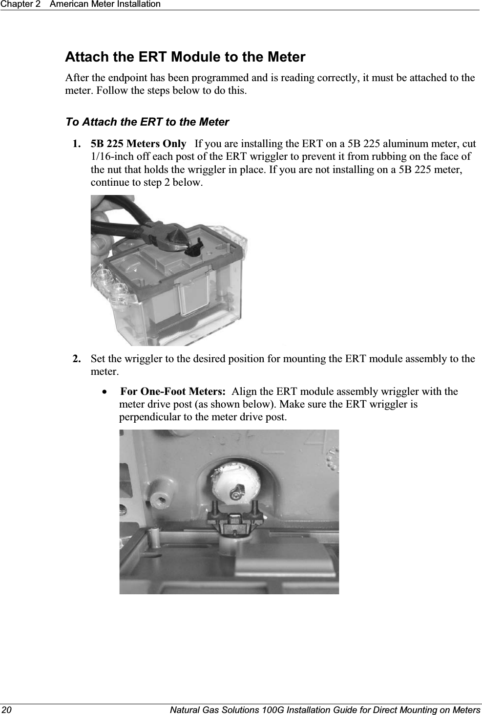
Itron, Inc. Utility meter transceiver 100G Installation Guide draft 102808
Itron >
Contents
- 1. Users Manual p1
- 2. Users Manual p2
- 3. Users Manual p3
- 4. Users Manual p4
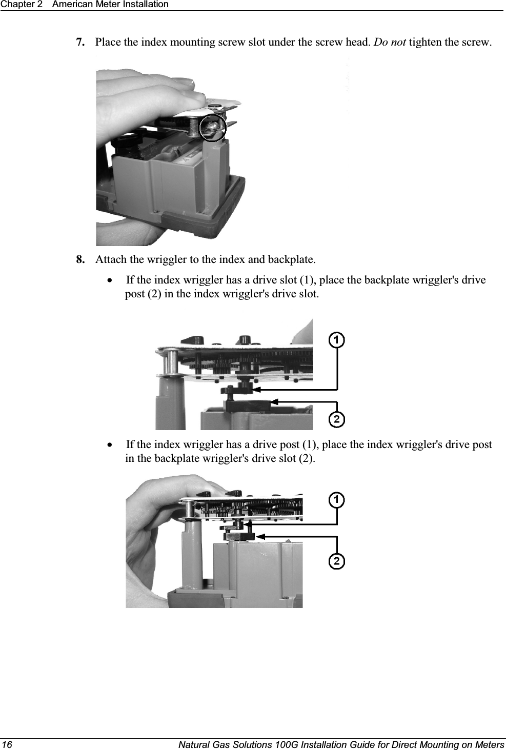
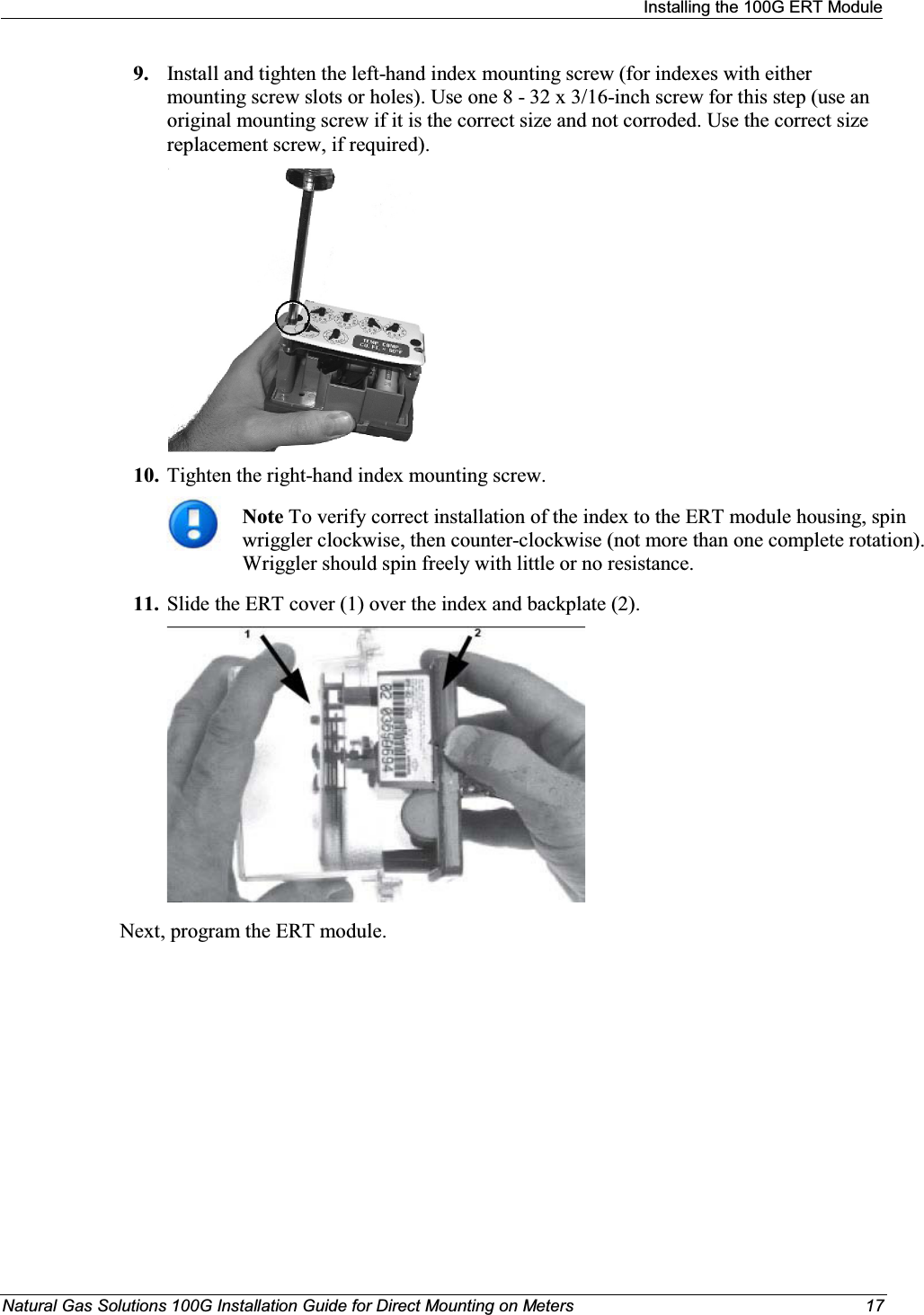
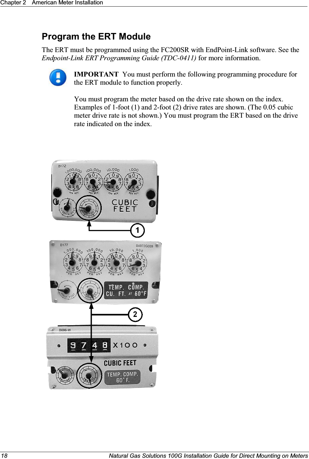
Users Manual p1
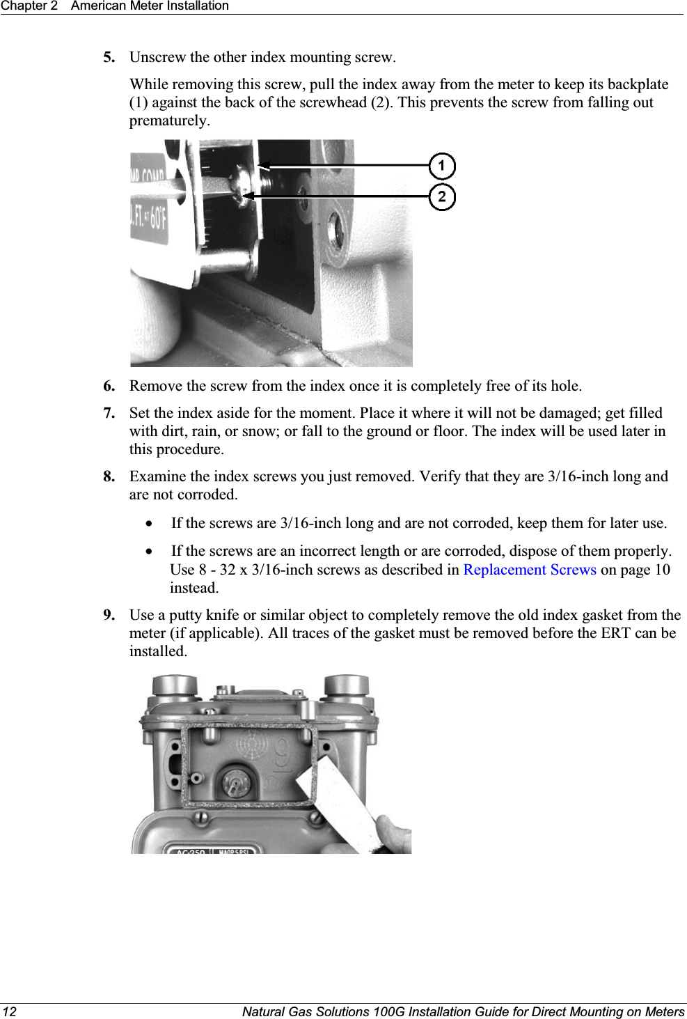
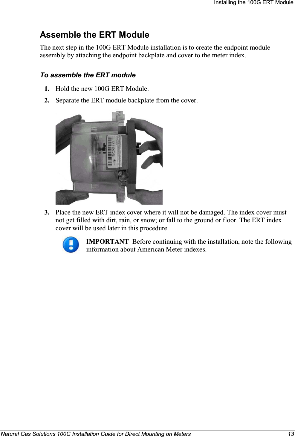
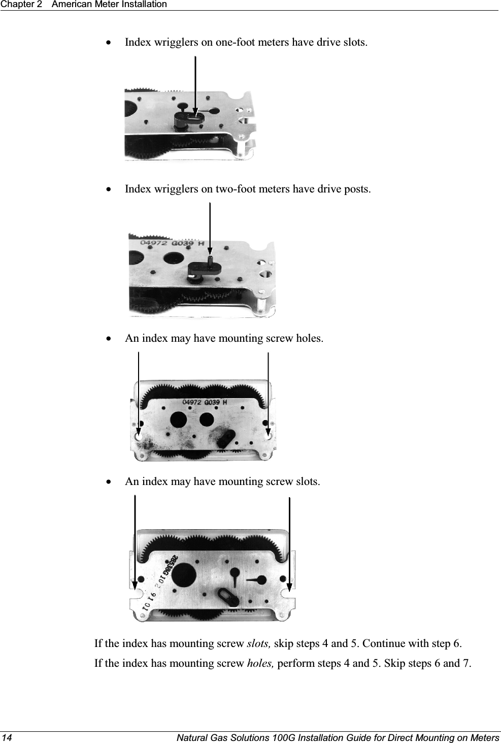
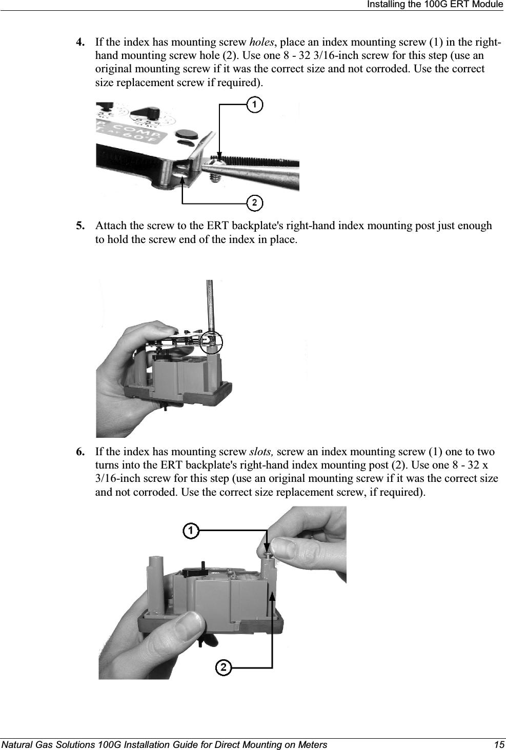
![IRU'LUHFW0RXQWLQJRQ0HWHUV3DUWQXPEHU38%5HYLVLRQ%(573DUW1XPEHUV(5*(5*(5*(5*(5*(5*(5*(5*(5*(5*(5*,WURQ,QF$OOULJKWVUHVHUYHG,WURQLVDUHJLVWHUHGWUDGHPDUNRI,WURQ,QF$OORWKHUSURGXFWQDPHVDQGORJRVLQWKLVGRFXPHQWDWLRQDUHXVHGIRULGHQWLILFDWLRQSXUSRVHVRQO\DQGPD\EHWUDGHPDUNVRUUHJLVWHUHGWUDGHPDUNVRIWKHLUUHVSHFWLYHFRPSDQLHV,I\RXKDYHFRPPHQWVRUVXJJHVWLRQVRQKRZZHPD\LPSURYHWKLVGRFXPHQWDWLRQVHQGWKHPWR7HFKQLFDO&RPPXQLFDWLRQV0DQDJHU#LWURQFRP,I\RXKDYHTXHVWLRQVRUFRPPHQWVDERXWWKHVRIWZDUHRUKDUGZDUHSURGXFWFRQWDFW,WURQ7HFKQLFDO6XSSRUWx,QWHUQHWZZZLWURQFRPx(PDLOVXSSRUW#LWURQFRPx3KRQH863DWHQW1XPEHUV&DQDGLDQ3DWHQW1XPEHUV7KLVGHYLFHFRPSOLHVZLWK3DUWRIWKH)&&5XOHV2SHUDWLRQRIWKLVGHYLFHLVVXEMHFWWRWKHIROORZLQJWZRFRQGLWLRQVx7KLVGHYLFHPD\QRWFDXVHKDUPIXOLQWHUIHUHQFHx7KLVGHYLFHPXVWDFFHSWDQ\LQWHUIHUHQFHWKDWPD\FDXVHXQGHVLUDEOHRSHUDWLRQ7KLVGHYLFHPXVWEHSHUPDQHQWO\PRXQWHGVXFKWKDWLWUHWDLQVDGLVWDQFHRIFHQWLPHWHUVLQFKHVIURPDOOSHUVRQVLQRUGHUWRFRPSO\ZLWK)&&5)H[SRVXUHOHYHOV7KLVHTXLSPHQWKDVEHHQWHVWHGDQGIRXQGWRFRPSO\ZLWKWKHOLPLWVSXUVXDQWWR3DUWRIWKH)&&5XOHV7KHVHOLPLWVDUHGHVLJQHGWRSURYLGHUHDVRQDEOHSURWHFWLRQDJDLQVWKDUPIXOLQWHUIHUHQFHLQDUHVLGHQWLDOLQVWDOODWLRQ2SHUDWLRQLVVXEMHFWWRWKHIROORZLQJFRQGLWLRQVx7KLVGHYLFHPD\QRWFDXVHLQWHUIHUHQFHx7KLVGHYLFHPXVWDFFHSWDQ\LQWHUIHUHQFHWKDWPD\FDXVHXQGHVLUHGRSHUDWLRQRIWKHGHYLFH&RPSOLHVZLWK,&5667KH)HGHUDO$YLDWLRQ$GPLQLVWUDWLRQSURKLELWVRSHUDWLQJWUDQVPLWWHUVDQGUHFHLYHUVRQDOOFRPPHUFLDODLUFUDIW:KHQSRZHUHGWKH*(570RGXOHLVFRQVLGHUHGDQRSHUDWLQJWUDQVPLWWHUDQGUHFHLYHUDQGFDQQRWEHVKLSSHGE\DLU$OOSURGXFWUHWXUQVPXVWEHVKLSSHGE\JURXQGWUDQVSRUWDWLRQ7RHQVXUHV\VWHPSHUIRUPDQFHWKLVGHYLFHDQGDQWHQQDVKDOOQRWEHFKDQJHGRUPRGLILHGZLWKRXWWKHH[SUHVVHGDSSURYDORI,WURQ$Q\XQDXWKRUL]HGPRGLILFDWLRQZLOOYRLGWKHXVHU¶VDXWKRULW\WRRSHUDWHWKHHTXLSPHQWWarning Only authorized Itron personnel should attempt repairs on Itron equipment. Attempts to do so by others might void any maintenance contract with your company. WarningxFollow these procedures to avoid injury to yourself or others.xThe lithium battery may cause a fire or chemical burn if it is not disposed of properly.xDo not recharge, disassemble, heat, or incinerate the lithium battery.xKeep the lithium battery away from children.](https://usermanual.wiki/Itron/100GDLA.Users-Manual-p1/User-Guide-1042557-Page-2.png)