Itron 100GDLA utility meter transceiver User Manual 100G Installation Guide draft 102808
Itron, Inc. utility meter transceiver 100G Installation Guide draft 102808
Itron >
Contents
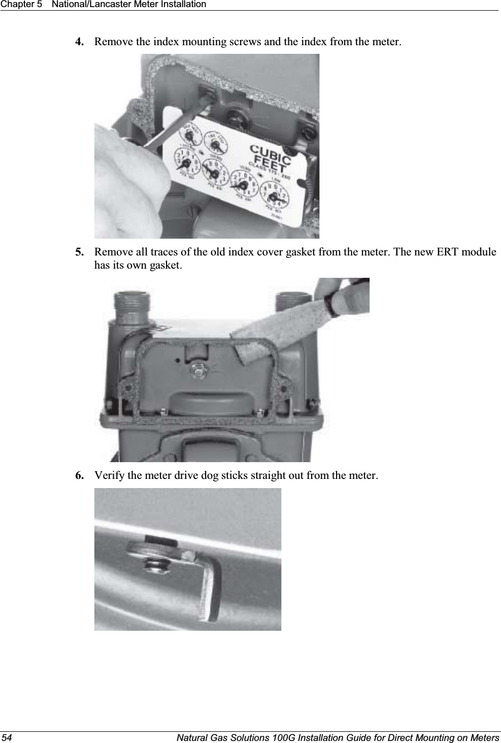
- 1. Users Manual p1
- 2. Users Manual p2
- 3. Users Manual p3
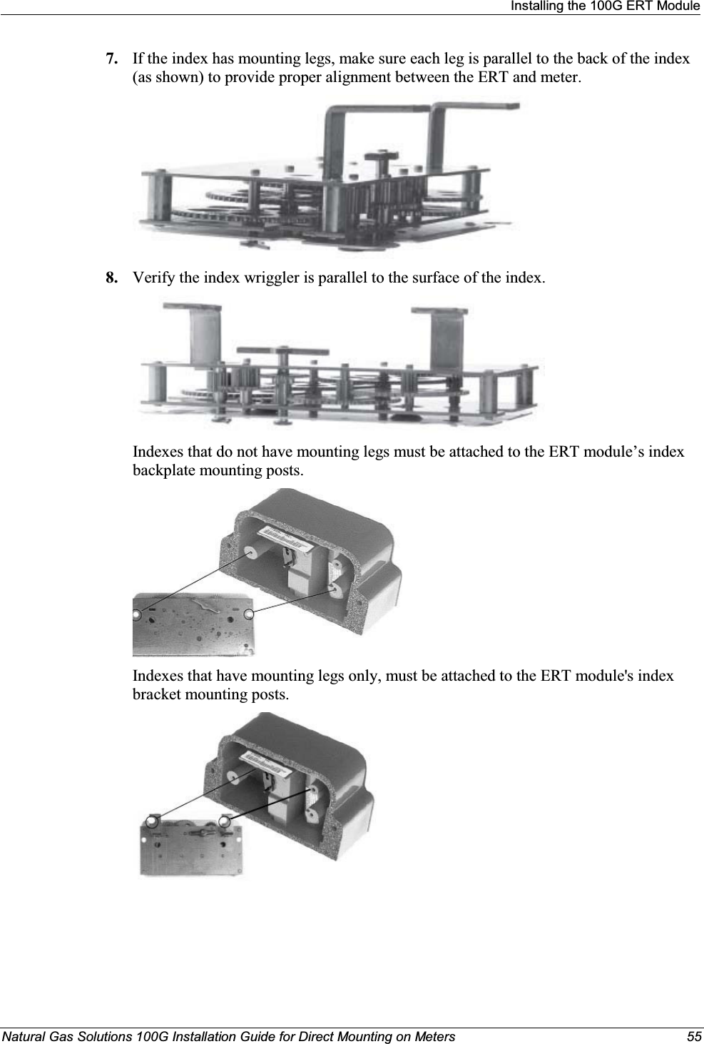
- 4. Users Manual p4
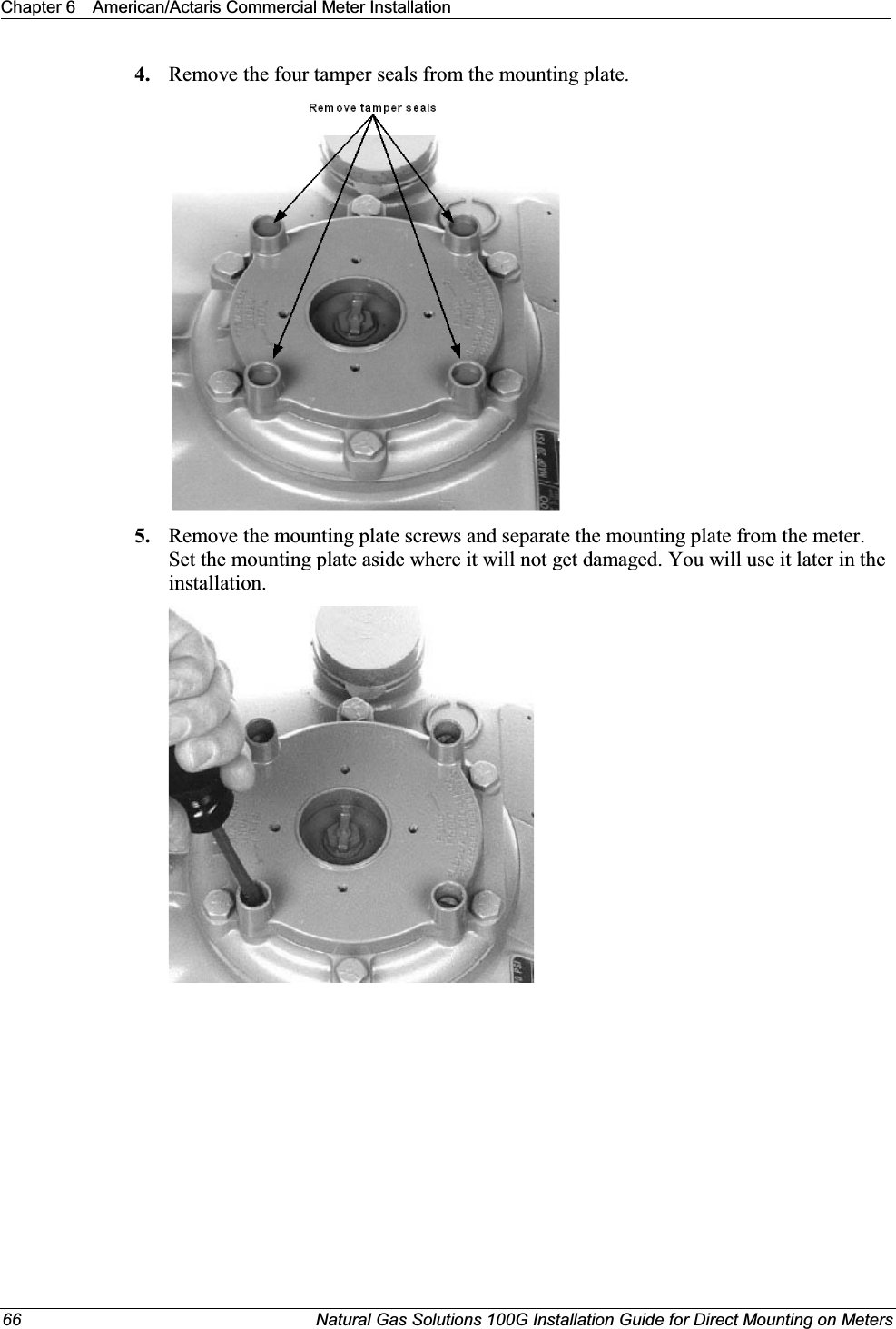
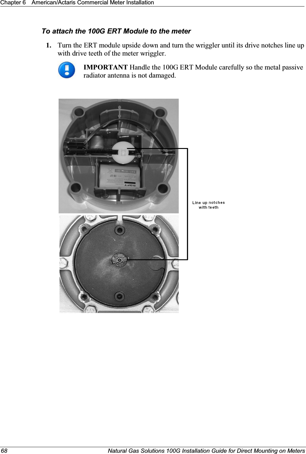
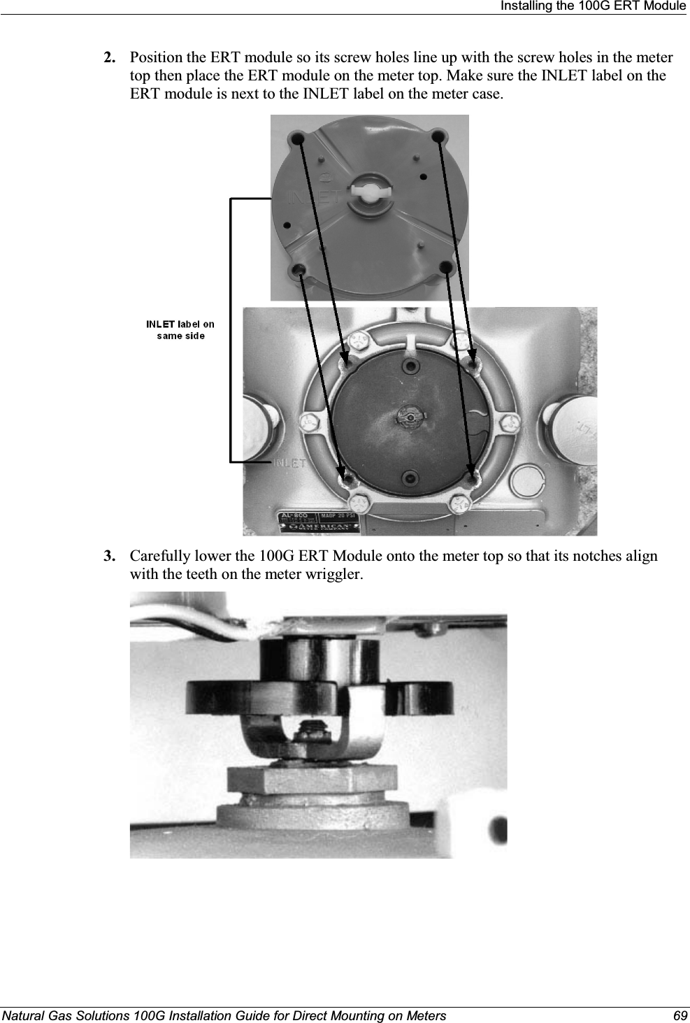
Users Manual p3