Itron 100GDLAS AMR transceiver device for utility meters User Manual
Itron Inc AMR transceiver device for utility meters Users Manual
Itron >
Contents
- 1. Users Manual 1
- 2. Users Manual 2
- 3. Users Manual
Users Manual

Natural Gas Solutions
100G Series Gas ERT Module Installation Guide,
Direct Mount
TDC-0823-014

Identification
100G Series ERT Module Installation Guide, Direct Mount
6 July 2016 TDC-0823-014
100G, 100G DL, 100G DLN, 100G DLS, 100G DLT
ERT module part numbers: 100G: ERG-5000-001, ERG-5000-002, ERG-5000-003, ERG-5000-004, ERG-5000-005, ERG-5000-006, ERG-5000-007, ERG-5000-008
100G Datalogging: ERG-5002-001, ERG-5002-002, ERG-5002-003, ERG-5002-004, ERG-5002-005, ERG-5002-006, ERG-5002-007, ERG-5002-008
100G Datalogging FN: ERG-5003-001, ERG-5003-002, ERG-5003-003, ERG-5003-004, ERG-5003-005, ERG-5003-006, ERG-5003-007, ERG-5003-008, ERG-5003-009
100G DLS: ERG-5006-001, ERG-5006-002, ERG-5006-003, ERG-5006-004, ERG-5006-005, ERG-5006-006, ERG-5006-007, ERG-5006-008, ERG-5006-009
100G DLT: ERG-5007-001, ERG-5007-002, ERG-5007-003, ERG-5007-004, ERG-5007-005, ERG-5007-006, ERG-5007-007, ERG-5007-008, ERG-5007-009
Copyright
© 2010 - 2016 Itron, Inc. All rights reserved.
Confidentiality Notice
The information contained herein is proprietary and confidential and is provided subject to the condition that (i) it is held in confidence except to the extent required otherwise by law and (ii) it is
used only for the purposes described herein. Any third party given access to this information is similarly bound in writing.
Trademark Notice
Itron is a registered trademark of Itron, Inc.
All other product names and logos in this documentation are used for identification purposes only and may be trademarks or registered trademarks of their respective companies.
Applicable Patents
U.S. Patent Numbers: 4,614,945; 4,753,169; 4,768,903; 4,799,059; 4,867,700
Canadian Patent Numbers: 1,254,949; 1,267,936; 1,282,118
Compliance Statement
This device complies with Part 15 of the FCC Rules. These limits are designed to provide reasonable protection against harmful interference in a residential installation. Operation is subject to
the following two conditions:
• This device may not cause harmful interference.
• This device must accept any interference that may cause undesirable operation.
This device must be permanently mounted such that it retains a distance of 20 centimeters (7.9 inches) from all persons in order to comply with FCC RF exposure levels.
This equipment has been tested and found to comply with the limits for a Class B digital device, pursuant to Part 15 of the FCC Rules. These limits are designed to provide reasonable
protection against harmful interference in a residential installation. This equipment generates, uses, and can radiate radio frequency energy and, if not installed and used in accordance with the
instructions, may cause harmful interference to radio communications. However, there is no guarantee that interference will not occur in a particular installation.
If this equipment does cause harmful interference to radio or television reception, which can be determined by turning the equipment off and on, the user is encouraged to try to correct the
interference by one or more of the following measures:
• Reorient or relocate the receiving antenna.
• Increase the separation between the equipment and receiver.
• Connect the equipment into an outlet on a circuit different from that to which the receiver is connected.
• Consult the dealer or an experienced radio or TV technician for help.
Compliance Statement
This equipment complies with policies RSS-210 and RSS-GEN of the RSS-GEN of the Innovation,
Science and Economic Development Canada (ISED) rules. Operation is subject to the following
two conditions:
(1) this device may not cause interference, and
(2) this device must accept any interference, including interference that may cause undesired
operation of the device.
Déclaration de conformité
Le présent appareil est conforme aux CNR d'Industrie Canada applicables aux appareils radio exempts de
licence. L'exploitation est autorisée aux deux conditions suivantes:
(1) l'appareil ne doit pas produire de brouillage, et
(2) l'utilisateur de l'appareil doit accepter tout brouillage radioélectrique subi, même si le brouillage est
susceptible d'en compromettre le fonctionnement.
Transportation Classification
The Federal Aviation Administration prohibits operating transmitters and receivers on all commercial aircraft. When powered, any 100G series gas ERT is considered an operating transmitter
and receiver and cannot be shipped by air. All product returns must be shipped by ground transportation.
Modifications and Repairs
To ensure system performance, this device and antenna shall not be changed or modified without the expressed approval of Itron. Any unauthorized modification will void the user's authority to
operate the equipment.
Meter Installation/Removal
In the event of malfunction, all repairs should be performed by Itron. It is the responsibility of users requiring service to report the need for service to Itron.
Warning Follow these procedures to avoid injury to yourself or others:
• The lithium battery may cause a fire or chemical burn if it is not disposed of properly.
• Do not recharge, disassemble, heat above 100º Celsius (212º Fahrenheit), crush, expose to water, or
incinerate the lithium battery.
• Keep the lithium battery away from children.
• Fire, explosion, and severe burn hazard.
Warning Only authorized and qualified personnel should attempt to install or service Itron equipment. Attempts to do so
by others might void any maintenance contract with your company. Unauthorized service personnel might also be subject
to shock hazard on some Itron equipment if removal of protective covers is attempted.
Warning To prevent ignition of flammable or combustible atmospheres, disconnect power before servicing.
Warning Substitution of components may impair intrinsic safety.
Warning Electrostatic Ignition Hazard Ensure area is not hazardous when installing, servicing, cleaning or touching the
ERT module.
Warning Clean only with a damp cloth.
TDC-0823-014 100G Series Gas ERT Module Installation Guide, Direct Mount ii
Proprietary and Confidential

Warning ERT modules contain sensitive electronic components which can be damaged if the module is dropped from
heights greater than 36 inches. Product warranty coverage is contingent on not exceeding this drop height limitation.
Suggestions
If you have comments or suggestions on how we may improve this documentation, send them to TechnicalCommunicationsManager@itron.com
If you have questions or comments about the software or hardware product, contact Itron Technical Support:
The information included in this guide is current as of the date of publication. Information within this guide including software versions and product names are subject to change without notice.
Contact
• Internet: www.itron.com
• E-mail: support@itron.com
• Phone: 1 877 487 6602
TDC-0823-014 100G Series Gas ERT Module Installation Guide, Direct Mount iii
Proprietary and Confidential

TDC-0823-014 100G Series Gas ERT Module Installation Guide, Direct Mount iv
Proprietary and Confidential

Before You Begin ........................................................................................................ vii
Document Conventions ..................................................................................................................... vii
Document Purpose ............................................................................................................................ vii
About the 100G Gas ERT Module ................................................................................. 1
Transmission Modes ........................................................................................................................... 1
100G DLS ERT Module and Itron Security Manager .......................................................................... 2
Enabling 100G DLS ERT Module Security ............................................................................... 2
100G Series Gas ERT Module Specifications .................................................................................... 3
Related Documents ............................................................................................................................. 3
100G Gas ERT Module Meter Compatibility List ................................................................................ 4
Installation Prerequisites ................................................................................................................... 14
Installation Overview ............................................................................................................... 16
Elster American Meter Installation ............................................................................. 17
Removing the Meter Index ................................................................................................................ 17
Assembling the Gas ERT Module and Index .................................................................................... 18
Programming the 100G ERT Module Assembly ............................................................................... 20
Attaching the 100G ERT Module Assembly to the Meter ................................................................. 22
Sensus Meter Installation ........................................................................................... 24
Removing the Meter Index ................................................................................................................ 24
Assembling the Gas ERT Module and Index .................................................................................... 25
Programming the 100G Gas ERT Module Assembly ....................................................................... 27
Attaching the 100G Gas ERT Module Assembly to the Sensus Meter ............................................. 29
Itron Meter Installation ................................................................................................ 31
Removing the Meter Index ................................................................................................................ 31
Assembling the Gas ERT Module and Index .................................................................................... 32
Programming the Itron ERT Module Assembly ................................................................................. 34
Attaching the ERT Module Assembly to the Itron Meter ................................................................... 35
Attaching the ERT Module Assembly to Sprague Flat-faced Meters ................................................ 39
Securing Brass Meter Tags to Flat-faced Meters.............................................................................. 40
Attaching the ERT Module Assembly to a Sprague 175RM Meters ................................................. 42
Removing the Meter Index ...................................................................................................... 42
Assembling the Gas ERT Module and Index .......................................................................... 43
Programming the 100G ERT Module Assembly ..................................................................... 45
Installing the 100G Gas ERT Module Assembly on the Sprague 175RM Meter .................... 46
National (Lancaster) Meter Installation ...................................................................... 49
Removing the Meter Index ................................................................................................................ 49
Contents
TDC-0823-014 100G Series Gas ERT Module Installation Guide, Direct Mount v
Proprietary and Confidential

Contents
Assembling the Gas ERT Module and Index .................................................................................... 50
Programming the 100G Gas ERT Module Assembly ....................................................................... 53
Installing the 100G Gas ERT Module Assembly on the Meter .......................................................... 54
Elster American and Itron Commercial Meter Installation ....................................... 58
Removing the Index or Index Assembly from the Meter ................................................................... 58
Programming the 100G Datalogging FN Commercial Gas ERT ....................................................... 60
Attaching the Commercial 100G Gas ERT Module Assembly on the Commercial Meter ................ 62
Attaching the Commercial 100G Gas ERT Module to an Itron Commercial Meter ........................... 65
Programming the Commercial Gas ERT Module Assembly ............................................................. 69
Attaching the Commercial 100G Gas ERT Module Assembly on the Commercial Meter ................ 71
Sensus Commercial Meter Installation ...................................................................... 75
Removing the Index or Index Assembly from the Meter ................................................................... 75
Programming the Commercial Gas ERT Module Assembly ............................................................. 76
Installing the Commercial ERT Module Assembly to the Meter ........................................................ 78
Mounting a 100G DLS Gas ERT Module on a Rockwell 750 meter with an Aluminum BOX Direct
Reading (VDR) .................................................................................................................................. 81
Installing the Commercial ERT Module Assembly to the Meter ........................................................ 82
GE Oil & Gas Dresser Commercial Rotary Meter Installation .................................. 85
Installation Prerequisites ................................................................................................................... 85
Installation Examples ........................................................................................................................ 86
Programming the 100G Gas ERT Module Assembly ....................................................................... 87
B3, LMMA, and S3A CTR/TC GE Dresser Series Register Settings and Direct Drive Programming
Information......................................................................................................................................... 88
B3, LMMA and S3A CTR/TC Meter Drive Rates: Residential Direct Drive Programming* .... 89
Installing the Residential ERT Module Assembly to the GE Dresser Rotary Meter .......................... 90
Installing the Commercial Gas ERT Module Assembly on a GE Dresser Rotary Meter with an
Instrument Drive ................................................................................................................................ 91
Programming the Commercial Gas ERT Module .............................................................................. 91
B3, LMMA, and S3A CD/TD GE Dresser Meter Drive Rates ............................................................ 93
Completed Installation Examples ............................................................................................ 96
Romet Commercial Rotary Meter Installation ........................................................... 97
Installation Example .......................................................................................................................... 97
Programming the 100G Gas ERT Module Assembly ....................................................................... 97
Installing the Residential ERT Module Assembly to the Romet ........................................................ 99
Index ........................................................................................................................... 100
TDC-0823-014 100G Series Gas ERT Module Installation Guide, Direct Mount vi
Proprietary and Confidential

Document Conventions
The following documentation conventions are used in this installation guide:
Caution A Caution warns the installer that failure to follow the information in the note could
result in loss of data. Be sure to carefully read a Caution note and follow the advice or
instructions.
Warning A Warning alerts the installer about potential physical harm to the installer or
hardware. It is critical that you pay strict attention to Warning notes, read the information
carefully, and follow the advice or instructions.
Document Purpose
This installation guide provides step-by-step instructions for installing the 100G series gas ERT module on a
wide variety of meters. Mechanical installation procedures are identical for all 100G series gas ERT modules
based on form or meter type. Compatible meters are listed in the 100G Gas ERT Module Meter Compatibility
List.
B
efore You Begin
Tip A Tip provides the installer with extra hints or suggestions to make a task easier to perform
or a concept easier to understand.
Note A Note supplies generic information to the installer. The installer can ignore the
information and continue a task without suffering any adverse consequences.
TDC-0823-014 100G Series Gas ERT Module Installation Guide, Direct Mount vii
Proprietary and Confidential

Before You Begin
TDC-0823-014 100G Series Gas ERT Module Installation Guide, Direct Mount viii
Proprietary and Confidential

Itron 100G series gas ERT modules are radio-frequency (RF) devices designed to transmit meter data to an
RF meter reading device within transmission distance of the ERT module. The 100G gas ERT was designed
with a higher output power than earlier Itron gas ERT modules to achieve an increased RF transmission
distance. The 100G series gas ERT modules have greater output power to meet Itron mobile and fixed
network requirements. The first generation 100G gas ERT module offered high transmit power capability
which increased operational efficiency and reduced infrastructure costs. The 100G Datalogging gas ERT
module was enhanced to offer higher transmit power with data logging capability (time-stamped hourly
interval data) for both mobile and fixed network applications. Itron's 100G Datalogging Fixed Network
(DLN) gas ERT module added improved network performance through a higher transmit power,
accomplished using increased antenna efficiency and more robust optimized messaging structures. Itron's
100G series gas ERT module brings increased efficiency in SCM+ messaging and adds enhanced network
security. SCM+ messages expand the data fields within our standard consumption message to offer added
value. The enhancement of secure communications provides greater protection for bubble-up and two-way
messaging to prevent unauthorized users from gaining access to the system.
The 100G DLT Datalogging gas ERT module (100G DLT) is a hybrid in the Itron line of 100 Series radio
frequency (RF) gas meter modules. The 100G DLT combines the circuit board hardware of the 100G DLS
module with the SCM messaging used in the 100G DLN module. This allows utilities currently using the
SCM messaging in the 100G DLN can upgrade to the 100G DLT without the upgrades required for
programming, enhanced security, or meter reading. The 100G DLT does not offer the optional ISM enhanced
security capability or extended tamper information available in the 100G DLS.
Transmission Modes
The 100G series gas ERT module can be set to transmit in Fixed Network, Mobile and Handheld, or Hard to
Read Mobile and Handheld Mode.
• Fixed Network Mode. The 100G transmits a high-powered network interval message (NIM) RF
message every five minutes. Output power in this mode is 500 milliwatts or +27 dBm. Interspersed in the
high power NIM, the 100G DLS transmits a medium power RF message at 10 milliwatts or +10 dBm
every 60 seconds; expected battery life is 20 years.
• Mobile High Power Mode. The 100G transmits a high-powered RF message every 60 seconds. Output
power in this mode is 250 milliwatts or +24dbm; expected battery life is 20 years.
• Mobile and Handheld Mode. The 100G transmits a medium-powered RF message every 15 seconds.
Output power in this mode is 10 milliwatts or +10dBm; expected battery life is 20 years.
• (Optional) Hard to Read Mobile and Handheld Mode. The 100G transmits a high-powered RF
message every 30 seconds. Output power in this mode is 250 milliwatts or +24dBm; expected battery life
decreases to 15 years in this mode. The Hard to Read Mobile and Handheld Mode should only be used for
exceptionally hard-to-read applications (such as meters installed on roof tops or in sub-basements).
CHAPTER 1
A
bout the 100G Gas ERT Module
TDC-0823-014 100G Series Gas ERT Module Installation Guide, Direct Mount 1
Proprietary and Confidential

About the 100G Gas ERT Module
• Itron Cellular Solutions (ICS) Mode. The 100G DLS module is compatible with the Itron Cellular
Solution and can be programmed for optimum operation with FDM Endpoint Tools Enhanced. In ICS
mode, the 100G DLS transmits a high-powered network interval message (NIM) RF message every five
minutes. Output power in this mode is 500 milliwatts or +27 dBm. Interspersed in the high power NIM,
the 100G transmits a medium power RF message at 10 milliwatts or +10 dBm every 60 seconds; expected
battery life is 20 years.
Note ICS mode is for fixed network application only. ICS is optimized to work with the ICS
communications module in Itron’s electric meter. The 100G DLS must be in a full security mode to work
with ICS. This is not part of the ICS mode, but is a system level requirement.
An FCC license is not required to read 100G series gas ERT modules.
100G DLS ERT Module and Itron Security Manager
The 100G DLS ERT module is a component of Itron's ChoiceConnect system. ChoiceConnect system
enhanced security, provided by Itron Security Manager (ISM), applies to the RF communications between the
handheld computer, Mobile Collector, or Fixed Network system and the ERT module. ISM is available in the
100G DLS module only.
There are two fundamental security processes used in the ChoiceConnect system to ensure system
communication confidentiality and validity.
• Authentication. Authentication is the process of confirming that an artifact is genuine or valid.
Authentication in the 100G DLS is the process of verifying a request is from a valid source and in its
original form.
• Encryption. Encryption is the process of transforming information to make it unreadable to anyone who
does not have a valid security key. There are two types of encryption, symmetric and asymmetric.
Symmetric encryption uses a shared key to decrypt or encrypt information. Asymmetric encryption uses a
private key to encrypt and a public key to decrypt.
As a component of the Itron ChoiceConnect solution, the 100G DLS supports the security model found in the
ChoiceConnect solution for both reading and programming. If the 100G DLS modules are shipped without
ChoiceConnect enhanced security enabled (ready to secure), the utility can—at a later date—configure the
ERT modules for ISM enhanced security.
Note Enabling or working with Itron ISM enhanced security requires FDM Endpoint Tools Enhanced.
Enabling 100G DLS ERT Module Security
When 100G DLS ERT modules ship from an Itron factory, each module contains utility factory keys. The
presence of these utility factory keys does not enable the enhanced security; the installer enables the enhanced
100G DLS security at the time the ERT module is deployed or at a later time using an Itron programming
device, Field Deployment Manager Endpoint Tools Enhanced, and programming commands. Initial key
exchange commands are secured using the utility factory keys. For more information about programming the
100G DLS ERT module for security, see the FDM Endpoint Tools Mobile Application Guide (TDC-0934).
TDC-0823-014 100G Series Gas ERT Module Installation Guide, Direct Mount 2
Proprietary and Confidential

About the 100G Gas ERT Module
100G Series Gas ERT Module Specifications
Functional Specifications
Description
Power Source
100G
100G Datalogging
100G Datalogging FN
100G DLS Datalogging
100G DLT Datalogging
Two "A" cell lithium batteries
One "A" cell lithium battery
Tamper Detection
Tilt and cut cable
FCC Compliance
Part 15 certified
Industry Canada Compliance
RSS-210 certified
Intrinsically Safe per
UL Class I, Division 1, Groups C and D
Product Identification
Numeric and bar coded ERT type and serial number
Construction Materials
Gray polycarbonate housing and back plate with encapsulated electronics
Operational Specifications
Description
Operating Temperatures
-40° to 158° F (-40° to +70° C)
Operating Humidity
5 to 95 percent relative humidity
Program Frequency
908 MHz
Transmit Frequency
Frequency Hopping Spread spectrum 903 to 926.85 MHz in the ISM band
Data Integrity
Verified in every data message
NIM Message
FM modulation; all other messages are AM modulated
Related Documents
Document Title
Document Part Number
100G Series Gas ERT Module Installation Guide, Direct Mount TDC-0823-XXX
100 Series Modules and CENTRON Bridge Meter Tamper Reference Guide TDC-1028-XXX
100 Series Gas and Telemetry Module Technology Guide TDC-0825-XXX
Gas and Telemetry Module Meter Compatibility List PUB-0117-002
Gas and Telemetry Module Ordering Guide
PUB-0117-001
100G DLS Gas ERT Module Specification Sheet Publication 101274SP-XX
100G DLN Gas ERT Module Specification Sheet Publication 100941SP-XX
100G DLT Gas ERT Module Specification Sheet Publication 101365SP-XX
Field Deployment Manager Endpoint Tools Mobile Application Guide TDC-0934-XXX
Field Deployment Manager Field Representative's Guide TDC-0936-XXX
Note The last three digits of the user and installation guides represent the document's revision level. The
revision level is subject to change without notice.
TDC-0823-014 100G Series Gas ERT Module Installation Guide, Direct Mount 3
Proprietary and Confidential

About the 100G Gas ERT Module
100G Gas ERT Module Meter Compatibility List
The following table lists meter types compatible with the 100G series gas ERT module. Due to continuous
research and product improvements and enhancements, Itron reserves the right to change product or system
specifications without notice.
Elster American (Canadian)
Meter Model
Meter Notes
100G Module Type
Itron Part Number
Gas Module Notes
W75AL Aluminum case 100G
100G Datalogging
100G Datalogging FN
100G DLS Datalogging
100G DLT Datalogging
ERG-5000-001
ERG-5002-001
ERG-5003-001
ERG-5006-001
ERG-5007-001
AC-175 Aluminum case 100G
100G Datalogging
100G Datalogging FN
100G DLS Datalogging
100G DLT Datalogging
ERG-5000-001
ERG-5002-001
ERG-5003-001
ERG-5006-001
ERG-5007-001
AL-175 Aluminum case 100G
100G Datalogging
100G Datalogging FN
100G DLS Datalogging
100G DLT Datalogging
ERG-5000-001
ERG-5002-001
ERG-5003-001
ERG-5006-001
ERG-5007-001
ALC-175 Aluminum case 100G
100G Datalogging
100G Datalogging FN
100G DLS Datalogging
100G DLT Datalogging
ERG-5000-001
ERG-5002-001
ERG-5003-001
ERG-5006-001
ERG-5007-001
AT-175 Aluminum case 100G
100G Datalogging
100G Datalogging FN
100G DLS Datalogging
100G DLT Datalogging
ERG-5000-001
ERG-5002-001
ERG-5003-001
ERG-5006-001
ERG-5007-001
AT-210 Aluminum case 100G
100G Datalogging
100G Datalogging FN
100G DLS Datalogging
100G DLT Datalogging
ERG-5000-001
ERG-5002-001
ERG-5003-001
ERG-5006-001
ERG-5007-001
AL-225 Aluminum case, Canada
only 100G
100G Datalogging
100G Datalogging FN
100G DLS Datalogging
100G DLT Datalogging
ERG-5000-001
ERG-5002-001
ERG-5003-001
ERG-5006-001
ERG-5007-001
5B-225 Aluminum case 100G
100G Datalogging
100G Datalogging FN
100G DLS Datalogging
100G DLT Datalogging
ERG-5000-001
ERG-5002-001
ERG-5003-001
ERG-5006-001
ERG-5007-001
Must cut 1/16" off the
end of the module
wriggler drive post
which will make the
module incompatible
with other 2-ft. drive
meters.
AC-250 Aluminum case 100G
100G Datalogging
100G Datalogging FN
100G DLS Datalogging
100G DLT Datalogging
ERG-5000-001
ERG-5002-001
ERG-5003-001
ERG-5006-001
ERG-5007-001
TDC-0823-014 100G Series Gas ERT Module Installation Guide, Direct Mount 4
Proprietary and Confidential

About the 100G Gas ERT Module
Elster American (Canadian)
Meter Model
Meter Notes
100G Module Type
Itron Part Number
Gas Module Notes
AL-250 Aluminum case 100G
100G Datalogging
100G Datalogging FN
100G DLS Datalogging
100G DLT Datalogging
ERG-5000-001
ERG-5002-001
ERG-5003-001
ERG-5006-001
ERG-5007-001
AM-250 Aluminum case 100G
100G Datalogging
100G Datalogging FN
100G DLS Datalogging
100G DLT Datalogging
ERG-5000-001
ERG-5002-001
ERG-5003-001
ERG-5006-001
ERG-5007-001
AR-250 Aluminum case 100G
100G Datalogging
100G Datalogging FN
100G DLS Datalogging
100G DLT Datalogging
ERG-5000-001
ERG-5002-001
ERG-5003-001
ERG-5006-001
ERG-5007-001
AT-250 Aluminum case 100G
100G Datalogging
100G Datalogging FN
100G DLS Datalogging
100G DLT Datalogging
ERG-5000-001
ERG-5002-001
ERG-5003-001
ERG-5006-001
ERG-5007-001
AL-310 Aluminum case 100G
100G Datalogging
100G Datalogging FN
100G DLS Datalogging
100G DLT Datalogging
ERG-5000-001
ERG-5002-001
ERG-5003-001
ERG-5006-001
ERG-5007-001
AL-350 Aluminum case 100G
100G Datalogging
100G Datalogging FN
100G DLS Datalogging
100G DLT Datalogging
ERG-5000-001
ERG-5002-001
ERG-5003-001
ERG-5006-001
ERG-5007-001
AL-425 Aluminum case 100G
100G Datalogging
100G Datalogging FN
100G DLS Datalogging
100G DLT Datalogging
ERG-5000-001
ERG-5002-001
ERG-5003-001
ERG-5006-001
ERG-5007-001
AC-630 Aluminum case 100G
100G Datalogging
100G Datalogging FN
100G DLS Datalogging
100G DLT Datalogging
ERG-5000-001
ERG-5002-001
ERG-5003-001
ERG-5006-001
ERG-5007-001
AC-800 Aluminum case 100G
100G Datalogging
100G Datalogging FN
100G DLS Datalogging
100G DLT Datalogging
ERG-5000-001
ERG-5002-001
ERG-5003-001
ERG-5006-001
ERG-5007-001
AL800 Top mount index 100G
100G Datalogging
100G Datalogging FN
100G DLS Datalogging
100G DLT Datalogging
ERG-5000-007
ERG-5002-007
ERG-5003-007
ERG-5006-007
ERG-5007-007
AL1000 Top mount index 100G
100G Datalogging
100G Datalogging FN
100G DLS Datalogging
100G DLT Datalogging
ERG-5000-001
ERG-5002-001
ERG-5003-001
ERG-5006-001
ERG-5007-001
TDC-0823-014 100G Series Gas ERT Module Installation Guide, Direct Mount 5
Proprietary and Confidential

About the 100G Gas ERT Module
Elster American (Canadian)
Meter Model
Meter Notes
100G Module Type
Itron Part Number
Gas Module Notes
AL1400 Top mount index 100G
100G Datalogging
100G Datalogging FN
100G DLS Datalogging
100G DLT Datalogging
ERG-5000-007
ERG-5002-007
ERG-5003-007
ERG-5006-007
ERG-5007-007
AL2300 Top mount index 100G
100G Datalogging
100G Datalogging FN
100G DLS Datalogging
100G DLT Datalogging
ERG-5000-007
ERG-5002-007
ERG-5003-007
ERG-5006-007
ERG-5007-007
AL3000 Top mount index 100G
100G Datalogging
100G Datalogging FN
100G DLS Datalogging
100G DLT Datalogging
ERG-5000-007
ERG-5002-007
ERG-5003-007
ERG-5006-007
ERG-5007-007
AL5000 Top mount index 100G
100G Datalogging
100G Datalogging FN
100G DLS Datalogging
100G DLT Datalogging
ERG-5000-007
ERG-5002-007
ERG-5003-007
ERG-5006-007
ERG-5007-007
35B Iron case 100G
100G Datalogging
100G Datalogging FN
100G DLS Datalogging
100G DLT Datalogging
ERG-5000-007
ERG-5002-007
ERG-5003-007
ERG-5006-007
ERG-5007-007
60B Iron case 100G
100G Datalogging
100G Datalogging FN
100G DLS Datalogging
100G DLT Datalogging
ERG-5000-007
ERG-5002-007
ERG-5003-007
ERG-5006-007
ERG-5007-007
80B Iron case, must have front-
reading index 100G
100G Datalogging
100G Datalogging FN
100G DLS Datalogging
100G DLT Datalogging
ERG-5000-007
ERG-5002-007
ERG-5003-007
ERG-5006-007
ERG-5007-007
250B Iron case 100G
100G Datalogging
100G Datalogging FN
100G DLS Datalogging
100G DLT Datalogging
ERG-5000-007
ERG-5002-007
ERG-5003-007
ERG-5006-007
ERG-5007-007
500B Iron case 100G
100G Datalogging
100G Datalogging FN
100G DLS Datalogging
100G DLT Datalogging
ERG-5000-007
ERG-5002-007
ERG-5003-007
ERG-5006-007
ERG-5007-007
Rotary RPM Series
(No pulser, no
instrument)
Use Elster American kit
numbers 93179K002, 003,
004, or 005 to modify the
meter with an adapter to
attach a residential gas
module. Purchase adapter
from Elster American.
100G
100G Datalogging
100G Datalogging FN
100G DLS Datalogging
100G DLT Datalogging
ERG-5000-001
ERG-5002-001
ERG-5003-001
ERG-5006-001
ERG-5007-001
TDC-0823-014 100G Series Gas ERT Module Installation Guide, Direct Mount 6
Proprietary and Confidential

About the 100G Gas ERT Module
Elster American (Canadian)
Meter Model
Meter Notes
100G Module Type
Itron Part Number
Gas Module Notes
Rotary RPM Series Instrument platform with
mechanical drive. 100G
100G Datalogging
100G Datalogging FN
100G DLS Datalogging
100G DLT Datalogging
ERG-5000-007
ERG-5002-007
ERG-5003-007
ERG-5006-007
ERG-5007-007
GE Oil & Gas/Dresser Meters
Meter Model
Meter Notes
100G Module Type
Itron Part Number
Gas Module Notes
Series B3
8C—56M CTR
8C—16M TC
(No pulser,
No instrument drive)
To attach an Elster
American residential ERT
module, install GE Dresser’s
Elster American AMR
adapter kit, P/N 059599-000.
Purchase AMR adapter from
GE Dresser.
100G
100G Datalogging
100G Datalogging FN
100G DLS Datalogging
100G DLT Datalogging
ERG-5000-001
ERG-5002-001
ERG-5003-001
ERG-5006-001
ERG-5007-001
Series A
(LMMA)
1.5M—5M
CTR (No pulser, No
instrument drive)
To attach an Elster
American residential ERT
module, install GE Dresser’s
Elster American AMR
adapter kit, P/N 058530-610.
Purchase AMR adapter from
GE Dresser.
100G
100G Datalogging
100G Datalogging FN
100G DLS Datalogging
100G DLT Datalogging
ERG-5000-001
ERG-5002-001
ERG-5003-001
ERG-5006-001
ERG-5007-001
Series A
(LMMA)
7M—16M
CTR (No pulser, No
instrument drive)
To attach an Elster
American residential 100G
DLN, 100G DLS or 2.4GZ
gas module, install GE
Dresser’s Elster American
AMR adapter kit, P/N
058531-610. Purchase AMR
adapter from GE Dresser.
100G
100G Datalogging
100G Datalogging FN
100G DLS Datalogging
100G DLT Datalogging
ERG-5000-001
ERG-5002-001
ERG-5003-001
ERG-5006-001
ERG-5007-001
Series A
(LMMA)
1.5M—5M
TC (No pulser, No
instrument drive)
To attach an Elster
American residential ERT
module, install Dresser's
Elster American AMR
adapter kit, P/N 058224-641.
Purchase AMR adapter from
Dresser.
100G
100G Datalogging
100G Datalogging FN
100G DLS Datalogging
100G DLT Datalogging
ERG-5000-001
ERG-5002-001
ERG-5003-001
ERG-5006-001
ERG-5007-001
Series Z
5C/8C15 To attach an Elster
American residential 100G
DLN, 100G DLS or 2.4GZ
gas module, install GE
Dresser’s Elster American
AMR adapter kit, P/N
059847-000. Purchase AMR
adapter from GE Dresser.
100G
100G Datalogging
100G Datalogging FN
100G DLS Datalogging
100G DLT Datalogging
ERG-5000-001
ERG-5002-001
ERG-5003-001
ERG-5006-001
ERG-5007-001
Instrument drive
B3: CTR
TC, 8C—11M
LMMA: CTR
TC: 1.5M—11M
Instrument platform with
mechanical drive. 100G
100G Datalogging
100G Datalogging FN
100G DLS Datalogging
100G DLT Datalogging
100G
100G Datalogging
100G Datalogging FN
100G DLS Datalogging
100G DLT Datalogging
ERG-5000-007
ERG-5002-007
ERG-5003-007
ERG-5006-007
ERG-5007-007
ERG-5000-008
ERG-5002-008
ERG-5003-008
ERG-5006-008
ERG-5007-008
TDC-0823-014 100G Series Gas ERT Module Installation Guide, Direct Mount 7
Proprietary and Confidential

About the 100G Gas ERT Module
Itron (Actaris, Schlumberger, Sprague)
Meter Model Meter Notes 100G Module Type Itron Part Number Gas Module Notes
175 2-hole index cover
3-hole index cover
100G
100G Datalogging
100G Datalogging FN
100G DLS Datalogging
100G DLT Datalogging
ERG-5000-005
ERG-5002-005
ERG-5003-005
ERG-5006-005
ERG-5007-005
175 Combination 3-hole index cover
integrated regulator
2-hole index cover
100G
100G Datalogging
100G Datalogging FN
100G DLS Datalogging
100G DLT Datalogging
ERG-5000-005
ERG-5002-005
ERG-5003-005
ERG-5006-005
ERG-5007-005
175RM Flat-face meter
Regulator on back of meter 100G Datalogging FN
100G DLS Datalogging
100G DLT Datalogging
ERG-5003-009
ERG-5006-009
ERG-5007-009
175WC 3-hole index cover 100G
100G Datalogging
100G Datalogging FN
100G DLS Datalogging
100G DLT Datalogging
ERG-5000-005
ERG-5002-005
ERG-5003-005
ERG-5006-005
ERG-5007-005
210 Slant-face meter 100G
100G Datalogging
100G Datalogging FN
100G DLS Datalogging
100G DLT Datalogging
ERG-5000-005
ERG-5002-005
ERG-5003-005
ERG-5006-005
ERG-5007-005
240 Slant-face meter 100G
100G Datalogging
100G Datalogging FN
100G DLS Datalogging
100G DLT Datalogging
ERG-5000-005
ERG-5002-005
ERG-5003-005
ERG-5006-005
ERG-5007-005
240 Flat-face meter
1-hole index cover 100G
100G Datalogging
100G Datalogging FN
100G DLS Datalogging
100G DLT Datalogging
ERG-5000-005
ERG-5002-005
ERG-5003-005
ERG-5006-005
ERG-5007-005
All modules require
Itron 1A Adapter Kit,
Itron P/N CFG-0015-
001.
240 2-hole index cover 100G
100G Datalogging
100G Datalogging FN
100G DLS Datalogging
100G DLT Datalogging
ERG-5000-005
ERG-5002-005
ERG-5003-005
ERG-5006-005
ERG-5007-005
240 Combination Integrated regulator 100G
100G Datalogging
100G Datalogging FN
100G DLS Datalogging
100G DLT Datalogging
ERG-5000-005
ERG-5002-005
ERG-5003-005
ERG-5006-005
ERG-5007-005
250 Slant-face 100G
100G Datalogging
100G Datalogging FN
100G DLS Datalogging
100G DLT Datalogging
ERG-5000-005
ERG-5002-005
ERG-5003-005
ERG-5006-005
ERG-5007-005
I-250 Slant-face 100G Datalogging FN
100G DLS Datalogging
100G DLT Datalogging
ERG-5003-005
ERG-5006-005
TDC-0823-014 100G Series Gas ERT Module Installation Guide, Direct Mount 8
Proprietary and Confidential

About the 100G Gas ERT Module
Itron (Actaris, Schlumberger, Sprague)
Meter Model Meter Notes 100G Module Type Itron Part Number Gas Module Notes
250WC Integrated regulator 100G
100G Datalogging
100G Datalogging FN
100G DLS Datalogging
100G DLT Datalogging
ERG-5000-005
ERG-5002-005
ERG-5003-005
ERG-5006-005
ERG-5007-005
METRIS 250 Slant-face 100G
100G Datalogging
100G Datalogging FN
100G DLS Datalogging
100G DLT Datalogging
ERG-5000-005
ERG-5002-005
ERG-5003-005
ERG-5006-005
ERG-5007-005
A longer mounting
screw may be
required when
retrofitting to some
vintage METRIS
meters. Longer
mounting screw is
Itron P/N 010626.
METRIS RM Slant-face meter, back inlet
and outlet 100G
100G Datalogging
100G Datalogging FN
100G DLS Datalogging
100G DLT Datalogging
ERG-5000-005
ERG-5002-005
ERG-5003-005
ERG-5006-005
ERG-5007-005
A longer mounting
screw may be
required when
retrofitting to some
vintage METRIS
meters. Longer
mounting screw is
Itron P/N 010626.
METRIS MB Slant-face meter, back inlet
and outlet without regulator 100G
100G Datalogging
100G Datalogging FN
100G DLS Datalogging
100G DLT Datalogging
ERG-5000-005
ERG-5002-005
ERG-5003-005
ERG-5006-005
ERG-5007-005
A longer mounting
screw may be
required when
retrofitting to some
vintage METRIS
meters. Longer
mounting screw is
Itron P/N 010626.
1A Flat-face meter includes 3-
dial, 2 cf indexes. 100G
100G Datalogging
100G Datalogging FN
100G DLS Datalogging
100G DLT Datalogging
ERG-5000-005
ERG-5002-005
ERG-5003-005
ERG-5006-005
ERG-5007-005
ERG-5007-005
Installation requires
Itron 1A Adapter Kit,
P/N CFG-0015-001.
305 Combination Integrated regulator 100G
100G Datalogging
100G Datalogging FN
100G DLS Datalogging
100G DLT Datalogging
ERG-5000-005
ERG-5002-005
ERG-5003-005
ERG-5006-005
ERG-5007-005
400 Slant-face meter 100G
100G Datalogging
100G Datalogging FN
100G DLS Datalogging
100G DLT Datalogging
ERG-5000-005
ERG-5002-005
ERG-5003-005
ERG-5006-005
ERG-5007-005
400A Slant-face meter 100G
100G Datalogging
100G Datalogging FN
100G DLS Datalogging
100G DLT Datalogging
ERG-5000-005
ERG-5002-005
ERG-5003-005
ERG-5006-005
ERG-5007-005
675A Top-mount index 100G
100G Datalogging
100G Datalogging FN
100G DLS Datalogging
100G DLT Datalogging
ERG-5000-007
ERG-5002-007
ERG-5003-007
ERG-5006-007
ERG-5007-007
Requires Itron
(Actaris) adapter P/N
8005901-001.
Purchase from Itron.
TDC-0823-014 100G Series Gas ERT Module Installation Guide, Direct Mount 9
Proprietary and Confidential

About the 100G Gas ERT Module
Itron (Actaris, Schlumberger, Sprague)
Meter Model Meter Notes 100G Module Type Itron Part Number Gas Module Notes
800A Top-mount index 100G
100G Datalogging
100G Datalogging FN
100G DLS Datalogging
100G DLT Datalogging
ERG-5000-007
ERG-5002-007
ERG-5003-007
ERG-5006-007
ERG-5007-007
Requires Itron
(Actaris) adapter P/N
8005901-001.
Purchase from Itron.
1000A Top-mount index 100G
100G Datalogging
100G Datalogging FN
100G DLS Datalogging
100G DLT Datalogging
ERG-5000-007
ERG-5002-007
ERG-5003-007
ERG-5006-007
ERG-5007-007
Requires Itron
(Actaris) adapter P/N
8005901-001.
Purchase from Itron.
National (Lancaster)
Meter Model
Meter Notes
100G Module Type
Itron Part Number
Gas Module Notes
175 National meter indexes with
bow-tie shaped wrigglers
cannot be used.
100G
100G Datalogging
100G Datalogging FN
100G DLS Datalogging
100G DLT Datalogging
ERG-5000-006
ERG-5002-006
ERG-5003-006
ERG-5006-006
ERG-5007-006
Actaris/Schlumberger/
Sprague direct read
(odometer) indexes
cannot be used.
U175
UL175 National meter indexes with
bow-tie shaped wrigglers
cannot be used.
100G
100G Datalogging
100G Datalogging FN
100G DLS Datalogging
100G DLT Datalogging
ERG-5000-006
ERG-5002-006
ERG-5003-006
ERG-5006-006
ERG-5007-006
Actaris/Schlumberger/
Sprague direct read
(odometer) indexes
cannot be used.
250 National meter indexes with
bow-tie shaped wrigglers
cannot be used.
100G
100G Datalogging
100G Datalogging FN
100G DLS Datalogging
100G DLT Datalogging
ERG-5000-006
ERG-5002-006
ERG-5003-006
ERG-5006-006
ERG-5007-006
Actaris/Schlumberger/
Sprague direct read
(odometer) indexes
cannot be used.
Romet
Meter Model Meter Notes 100G Module Type Itron Part Number Gas Module Notes
RM series No pulser,
no instrument drive Must purchase adapter kit
from Romet 100G
100G Datalogging
100G Datalogging FN
100G DLS Datalogging
100G DLT Datalogging
ERG-5000-001
ERG-5002-001
ERG-5003-001
ERG-5006-001
ERG-5007-001
RM series. Instrument
drive Instrument platform with
mechanical drive 100G
100G Datalogging
100G Datalogging FN
100G DLS Datalogging
100G DLT Datalogging
ERG-5000-007
ERG-5002-007
ERG-5003-007
ERG-5006-007
ERG-5007-007
Sensus (Invensys/Equimeter/Rockwell/EMCO)
Meter Model
Meter Notes
100G Module Type
Iron Part Number
Gas Module Notes
RT-100 18-tooth 100G
100G Datalogging
100G Datalogging FN
100G DLS Datalogging
100G DLT Datalogging
ERG-5000-004
ERG-5002-004
ERG-5003-004
ERG-5006-004
ERG-5007-004
S-110 11-tooth 100G
100G Datalogging
100G Datalogging FN
100G DLS Datalogging
100G DLT Datalogging
ERG-5000-002
ERG-5002-002
ERG-5003-002
ERG-5006-002
ERG-5007-002
TDC-0823-014 100G Series Gas ERT Module Installation Guide, Direct Mount 10
Proprietary and Confidential

About the 100G Gas ERT Module
Sensus (Invensys/Equimeter/Rockwell/EMCO)
Meter Model
Meter Notes
100G Module Type
Iron Part Number
Gas Module Notes
T-110 11-tooth 100G
100G Datalogging
100G Datalogging FN
100G DLS Datalogging
100G DLT Datalogging
ERG-5000-002
ERG-5002-002
ERG-5003-002
ERG-5006-002
ERG-5007-002
S-120 11-tooth 100G
100G Datalogging
100G Datalogging FN
100G DLS Datalogging
100G DLT Datalogging
ERG-5000-002
ERG-5002-002
ERG-5003-002
ERG-5006-002
ERG-5007-002
T-120 11-tooth 100G
100G Datalogging
100G Datalogging FN
100G DLS Datalogging
100G DLT Datalogging
ERG-5000-002
ERG-5002-002
ERG-5003-002
ERG-5006-002
ERG-5007-002
R-175 11-tooth 100G
100G Datalogging
100G Datalogging FN
100G DLS Datalogging
100G DLT Datalogging
ERG-5000-002
ERG-5002-002
ERG-5003-002
ERG-5006-002
ERG-5007-002
S-175 18-tooth 100G
100G Datalogging
100G Datalogging FN
100G DLS Datalogging
100G DLT Datalogging
ERG-5000-004
ERG-5002-004
ERG-5003-004
ERG-5006-004
ERG-5007-004
S-190 18-tooth 100G
100G Datalogging
100G Datalogging FN
100G DLS Datalogging
100G DLT Datalogging
ERG-5000-004
ERG-5002-004
ERG-5003-004
ERG-5006-004
ERG-5007-004
R-200 11-tooth 100G
100G Datalogging
100G Datalogging FN
100G DLS Datalogging
100G DLT Datalogging
ERG-5000-002
ERG-5002-002
ERG-5003-002
ERG-5006-002
ERG-5007-002
RT-200 11-tooth 100G
100G Datalogging
100G Datalogging FN
100G DLS Datalogging
100G DLT Datalogging
ERG-5000-002
ERG-5002-002
ERG-5003-002
ERG-5006-002
ERG-5007-002
S-200 11-tooth 100G
100G Datalogging
100G Datalogging FN
100G DLS Datalogging
100G DLT Datalogging
ERG-5000-002
ERG-5002-002
ERG-5003-002
ERG-5006-002
ERG-5007-002
RC-225 11-tooth (Canadian only) 100G
100G Datalogging
100G Datalogging FN
100G DLS Datalogging
100G DLT Datalogging
ERG-5000-002
ERG-5002-002
ERG-5003-002
ERG-5006-002
ERG-5007-002
RT-225 11-tooth 100G
100G Datalogging
100G Datalogging FN
100G DLS Datalogging
100G DLT Datalogging
ERG-5000-002
ERG-5002-002
ERG-5003-002
ERG-5006-002
ERG-5007-002
TDC-0823-014 100G Series Gas ERT Module Installation Guide, Direct Mount 11
Proprietary and Confidential

About the 100G Gas ERT Module
Sensus (Invensys/Equimeter/Rockwell/EMCO)
Meter Model
Meter Notes
100G Module Type
Iron Part Number
Gas Module Notes
RC-230 11-tooth 100G
100G Datalogging
100G Datalogging FN
100G DLS Datalogging
100G DLT Datalogging
ERG-5000-002
ERG-5002-002
ERG-5003-002
ERG-5006-002
ERG-5007-002
RCM-230
(RC-230 Metric) 16-tooth 100G
100G Datalogging
100G Datalogging FN
100G DLS Datalogging
100G DLT Datalogging
ERG-5000-003
ERG-5002-003
ERG-5003-003
ERG-5006-003
ERG-5007-003
RT-230 11-tooth 100G
100G Datalogging
100G Datalogging FN
100G DLS Datalogging
100G DLT Datalogging
ERG-5000-002
ERG-5002-002
ERG-5003-002
ERG-5006-002
ERG-5007-002
250 11-tooth 100G
100G Datalogging
100G Datalogging FN
100G DLS Datalogging
100G DLT Datalogging
ERG-5000-002
ERG-5002-002
ERG-5003-002
ERG-5006-002
ERG-5007-002
Cubix250 11-tooth 100G
100G Datalogging
100G Datalogging FN
100G DLS Datalogging
100G DLT Datalogging
ERG-5000-002
ERG-5002-002
ERG-5003-002
ERG-5006-002
ERG-5007-002
MR-7 (Cubix250
Metric) 11-tooth 100G
100G Datalogging
100G Datalogging FN
100G DLS Datalogging
100G DLT Datalogging
ERG-5000-002
ERG-5002-002
ERG-5003-002
ERG-5006-002
ERG-5007-002
R-275 11-tooth 100G
100G Datalogging
100G Datalogging FN
100G DLS Datalogging
100G DLT Datalogging
ERG-5000-002
ERG-5002-002
ERG-5003-002
ERG-5006-002
ERG-5007-002
24- and 30-tooth
gears are not
compatible.
MR-8
(R-275 Metric) 16-tooth 100G
100G Datalogging
100G Datalogging FN
100G DLS Datalogging
100G DLT Datalogging
ERG-5000-003
ERG-5002-003
ERG-5003-003
ERG-5006-003
ERG-5007-003
24- and 30-tooth
gears are not
compatible.
RT-275 11-tooth 100G
100G Datalogging
100G Datalogging FN
100G DLS Datalogging
100G DLT Datalogging
ERG-5000-002
ERG-5002-002
ERG-5003-002
ERG-5006-002
ERG-5007-002
S-275 11-tooth (side connections) 100G
100G Datalogging
100G Datalogging FN
100G DLS Datalogging
100G DLT Datalogging
ERG-5000-002
ERG-5002-002
ERG-5003-002
ERG-5006-002
ERG-5007-002
MR-5
(S-275 Metric) 16-tooth 100G
100G Datalogging
100G Datalogging FN
100G DLS Datalogging
100G DLT Datalogging
ERG-5000-003
ERG-5002-003
ERG-5003-003
ERG-5006-003
ERG-5007-003
24- and 30-tooth
gears are not
compatible.
TDC-0823-014 100G Series Gas ERT Module Installation Guide, Direct Mount 12
Proprietary and Confidential

About the 100G Gas ERT Module
Sensus (Invensys/Equimeter/Rockwell/EMCO)
Meter Model
Meter Notes
100G Module Type
Iron Part Number
Gas Module Notes
MR-9
(R-315 Metric) 16-tooth 100G
100G Datalogging
100G Datalogging FN
100G DLS Datalogging
100G DLT Datalogging
ERG-5000-003
ERG-5002-003
ERG-5003-003
ERG-5006-003
ERG-5007-003
24- and 30-tooth
gears are not
compatible.
310 11-tooth 100G
100G Datalogging
100G Datalogging FN
100G DLS Datalogging
100G DLT Datalogging
ERG-5000-002
ERG-5002-002
ERG-5003-002
ERG-5006-002
ERG-5007-002
R-315 11-tooth 100G
100G Datalogging
100G Datalogging FN
100G DLS Datalogging
100G DLT Datalogging
ERG-5000-002
ERG-5002-002
ERG-5003-002
ERG-5006-002
ERG-5007-002
24- and 30-tooth
gears are not
compatible.
MR-9
(R-315 Metric) 16-tooth 100G
100G Datalogging
100G Datalogging FN
100G DLS Datalogging
100G DLT Datalogging
ERG-5000-003
ERG-5002-003
ERG-5003-003
ERG-5006-003
ERG-5007-003
24- and 30-tooth
gears are not
compatible.
RT-360 18-tooth 100G
100G Datalogging
100G Datalogging FN
100G DLS Datalogging
100G DLT Datalogging
ERG-5000-004
ERG-5002-004
ERG-5003-004
ERG-5006-004
ERG-5007-004
415 18-tooth. Older meters may
have gas module-to-meter
mounting-hole variations that
can make them incompatible.
100G
100G Datalogging
100G Datalogging FN
100G DLS Datalogging
100G DLT Datalogging
ERG-5000-004
ERG-5002-004
ERG-5003-004
ERG-5006-004
ERG-5007-004
24- and 30-tooth
gears are not
compatible.
MR-12
(415 Metric) 16-tooth 100G
100G Datalogging
100G Datalogging FN
100G DLS Datalogging
100G DLT Datalogging
ERG-5000-003
ERG-5002-003
ERG-5003-003
ERG-5006-003
ERG-5007-003
24- and 30-tooth
gears are not
compatible.
750 Vertical index only 100G
100G Datalogging
100G Datalogging FN
100G DLS Datalogging
100G DLT Datalogging
ERG-5000-008
ERG-5002-008
ERG-5003-008
ERG-5006-008
ERG-5007-008
1000 Vertical index only 100G
100G Datalogging
100G Datalogging FN
100G DLS Datalogging
100G DLT Datalogging
ERG-5000-008
ERG-5002-008
ERG-5003-008
ERG-5006-008
ERG-5007-008
1600 Vertical index only 100G
100G Datalogging
100G Datalogging FN
100G DLS Datalogging
100G DLT Datalogging
ERG-5000-008
ERG-5002-008
ERG-5003-008
ERG-5006-008
ERG-5007-008
3000 Vertical index only 100G
100G Datalogging
100G Datalogging FN
100G DLS Datalogging
100G DLT Datalogging
ERG-5000-008
ERG-5002-008
ERG-5003-008
ERG-5006-008
ERG-5007-008
TDC-0823-014 100G Series Gas ERT Module Installation Guide, Direct Mount 13
Proprietary and Confidential

About the 100G Gas ERT Module
Sensus (Invensys/Equimeter/Rockwell/EMCO)
Meter Model
Meter Notes
100G Module Type
Iron Part Number
Gas Module Notes
5000 Vertical index only 100G
100G Datalogging
100G Datalogging FN
100G DLS Datalogging
100G DLT Datalogging
ERG-5000-008
ERG-5002-008
ERG-5003-008
ERG-5006-008
ERG-5007-008
10000 Vertical index only 100G
100G Datalogging
100G Datalogging FN
100G DLS Datalogging
100G DLT Datalogging
ERG-5000-008
ERG-5002-008
ERG-5003-008
ERG-5006-008
ERG-5007-008
750, 1000, 1600,
3000, 5000, 10000 Aluminum box direct reading
(VDR) index 100G
100G Datalogging
100G Datalogging FN
100G DLS Datalogging
100G DLT Datalogging
ERG-5000-008
ERG-5002-008
ERG-5003-008
ERG-5006-008
ERG-5007-008
Requires Itron
mounting screws, P/N
SCR-0062-001. Must
purchase separately.
EMCO #2-1/2 100G
100G Datalogging
100G Datalogging FN
100G DLS Datalogging
100G DLT Datalogging
ERG-5000-008
ERG-5002-008
ERG-5003-008
ERG-5006-008
ERG-5007-008
EMCO #3 100G
100G Datalogging
100G Datalogging FN
100G DLS Datalogging
100G DLT Datalogging
ERG-5000-008
ERG-5002-008
ERG-5003-008
ERG-5006-008
ERG-5007-008
EMCO #4 100G
100G Datalogging
100G Datalogging FN
100G DLS Datalogging
100G DLT Datalogging
ERG-5000-008
ERG-5002-008
ERG-5003-008
ERG-5006-008
ERG-5007-008
EMCO #4-1/2 100G
100G Datalogging
100G Datalogging FN
100G DLS Datalogging
100G DLT Datalogging
ERG-5000-008
ERG-5002-008
ERG-5003-008
ERG-5006-008
ERG-5007-008
EMCO #5 100G
100G Datalogging
100G Datalogging FN
100G DLS Datalogging
100G DLT Datalogging
ERG-5000-008
ERG-5002-008
ERG-5003-008
ERG-5006-008
ERG-5007-008
Installation Prerequisites
Prior to installation, verify you have the following items:
• 100G series gas ERT modules designed for your specific brand of residential or commercial gas meters
(ERT modules include new tamper seals).
• A compatible meter (see the 100G Gas ERT Module Meter Compatibility List).
• A compatible index. Itron 100G series gas ERT modules are compatible with standard dial and direct-read
(odometer) indexes. Exceptions are noted on the 100G Gas ERT Module Meter Compatibility List.
TDC-0823-014 100G Series Gas ERT Module Installation Guide, Direct Mount 14
Proprietary and Confidential

About the 100G Gas ERT Module
• Installation tools (provided by installer or customer).
• Small and medium flat-blade or Phillips screwdrivers.
• Side-cutting pliers/wire snips.
• Small putty knife.
• Meter seals, wire seal, and seal press.
• 11/32-inch nut driver or other blunt tool.
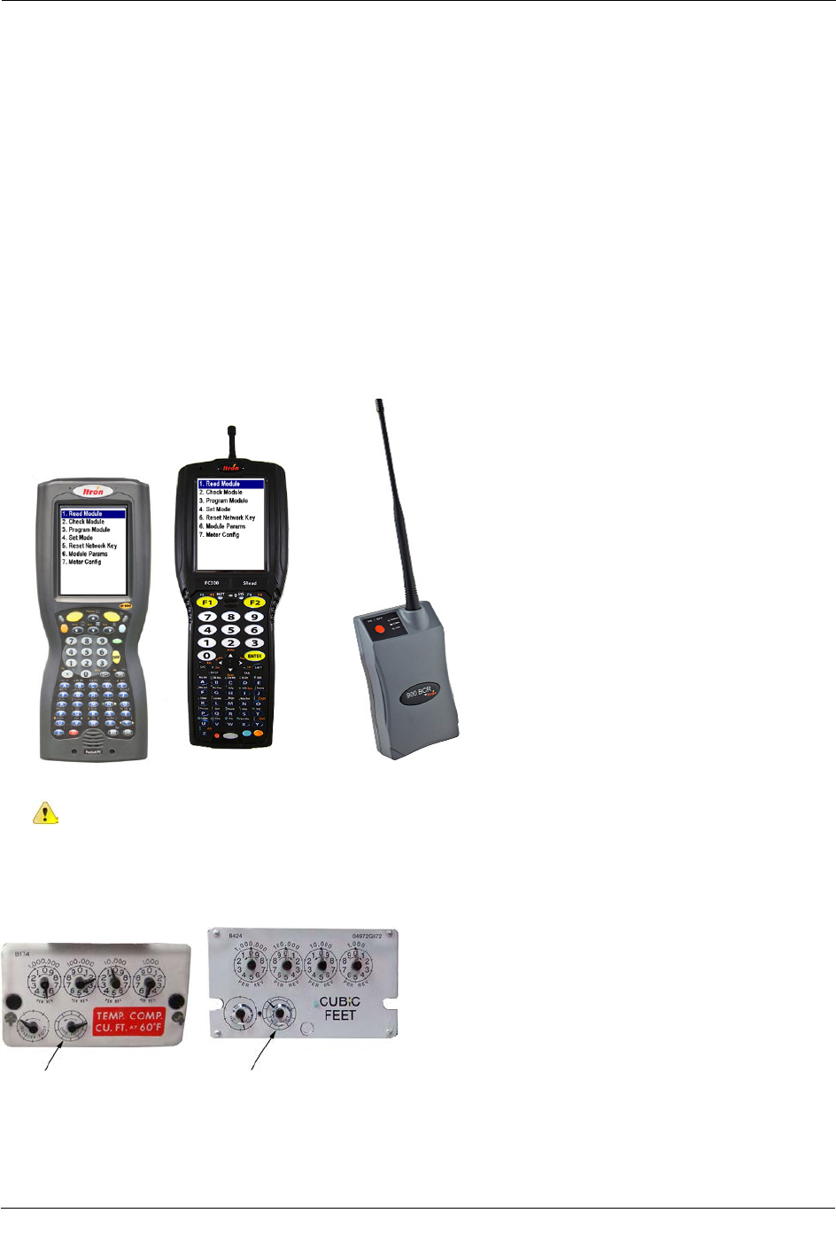
• Itron programming device:
FC200SR handheld computer with Field Deployment Manager (FDM) software
or
FC300 with SRead with Field Deployment Manager (FDM) software
or
900 MHz Belt Clip Radio with Field Deployment Manager (FDM) and a customer-supplied laptop
Note The FDM version required is dependent upon the 100G ERT module model in use.
• Replacement screws:
Replacement Screws
Meter To mount the 100G series
gas ERT module on the
meter:
Itron Part
Number To mount the index on the 100G
series gas ERT module housing: Itron Part
Number
Elster American 1/4 - 20 x 5/8" slotted, Fillister
head 8 - 32 x 3/16" slotted, Fillister head
Sensus/Rockwell 10 - 24 x 5/8" slotted, Fillister
head 6 - 32 x 5/8" slotted, Fillister head
Itron/Sprague
Sprague/Schlumberger 175
RM
10 - 24 x 5/8" slotted, Fillister
head
10 - 24 x 1/2-inch, slotted
Fillister head
SCR-0175-002
10 - 24 x 3/8" Fillister head 010040-002
National/Lancaster 10 - 24 x 3/4" Phillips, flat-
head, stainless steel SCR-0014-004 10 - 24 x 3/8" thread-forming, Phillips
pan-head to mount indexes with legs
6 - 19 x 3/8" thread-forming, Phillips,
Fillister head to mount indexes with
screw holes
SCR-0017-001
SCR-0037-001
Commercial Meter To mount the 100G
commercial ERT on the
meter:
Itron Part
Number To mount the index (and index
assembly, if applicable) on the
100G commercial ERT housing:
Itron Part
Number
Elster American 2A x 3.35" length, slotted
round-head drilled to accept
utility-approved wire seals
SCR-0062-001
12 - 24 x 1/2" slotted, Fillister head
machine screws, drilled to accept utility-
approved wire seals
Sensus 2A x 3.63" length, slotted
round-head drilled to accept
utility-approved wire seals
SCR-0062-002 2A x 2.94" length, slotted round-head SCR-0062-003
Rockwell For Aluminum Box Direct
Reading (VDR) index only SCR-0062-001
TDC-0823-014 100G Series Gas ERT Module Installation Guide, Direct Mount 15
Proprietary and Confidential

About the 100G Gas ERT Module
Installation Overview
Installing the 100G series gas ERT module on a meter involves four tasks:
1. Removing the index cover and index from the meter.
2. Assembling the 100G and index.
3. Programming the 100G assembly.
4. Attaching the 100G to the meter.
Warning ERT modules contain sensitive electronic components which can be damaged if
the module is dropped from heights greater than 36 inches. Product warranty coverage is
contingent on not exceeding this drop height limitation.
TDC-0823-014 100G Series Gas ERT Module Installation Guide, Direct Mount 16
Proprietary and Confidential
This chapter provides the instructions to install the ERT module on an Elster American Meter.
Removing the Meter Index
Begin the module installation by removing the index cover and index from the meter.
To remove the index from the meter
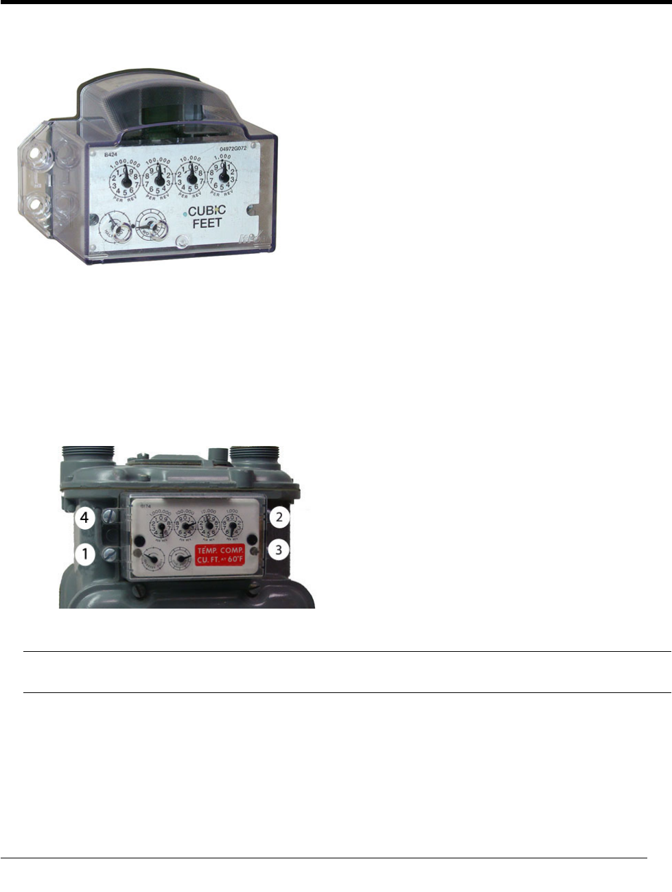
1. Remove the four index cover screws and the index cover from the Elster American meter. Alternate screw
removal following the numbered pattern in the photo.
2. Examine the mounting screws. If they are 5/8-inch long and not corroded, keep them to install the 100G
assembly to the meter. If the screws are not the correct length or if the screws are corroded, discard.
Note You may use the removed index cover as a temporary storage container for screws. Properly
dispose all unused screws, old index covers, gaskets, tamper seals, and other leftover materials.
CHAPTER 2
E
lster American Meter Installation
TDC-0823-014 100G Series Gas ERT Module Installation Guide, Direct Mount 17
Proprietary and Confidential
Elster American Meter Installation
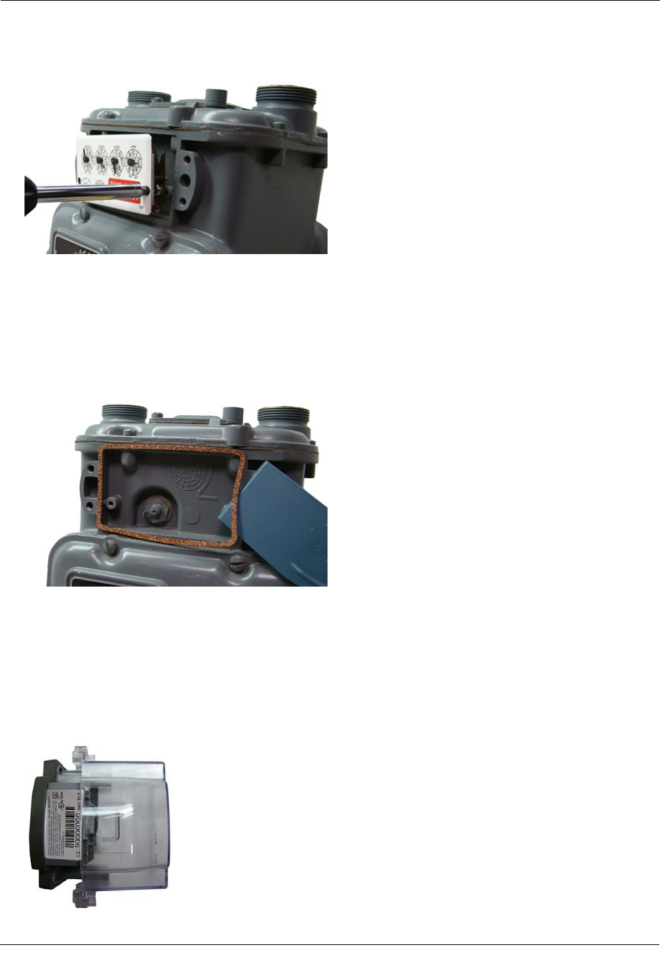
3. Unscrew one index mounting screw completely. Hold one hand under the index to catch the screw. While
you remove the other mounting screw, pull the index away from the meter to keep the index backplate
against the back of the screw. Remove the screw completely after the index is free of the meter.
Set the index aside where it will not be damaged or fill with dirt, rain or snow. You will mount the index
to the ERT module later in this procedure.
4. Verify the index mounting screws are 3/16-inch long and not corroded. If the screws are the correct length
and not corroded, retain for later use. If you discarded the original screws, use the correct replacement
screws (see Installation Prerequisites on page 14).
5. Remove the old gasket, gasket residue and dirt from the meter (if applicable). The meter face must be free
of gasket residue and foreign materials before you install the 100G series gas ERT module.
Assembling the Gas ERT Module and Index
Continue ERT module installation by assembling the ERT module and index.
To assemble the 100G series gas ERT module and index
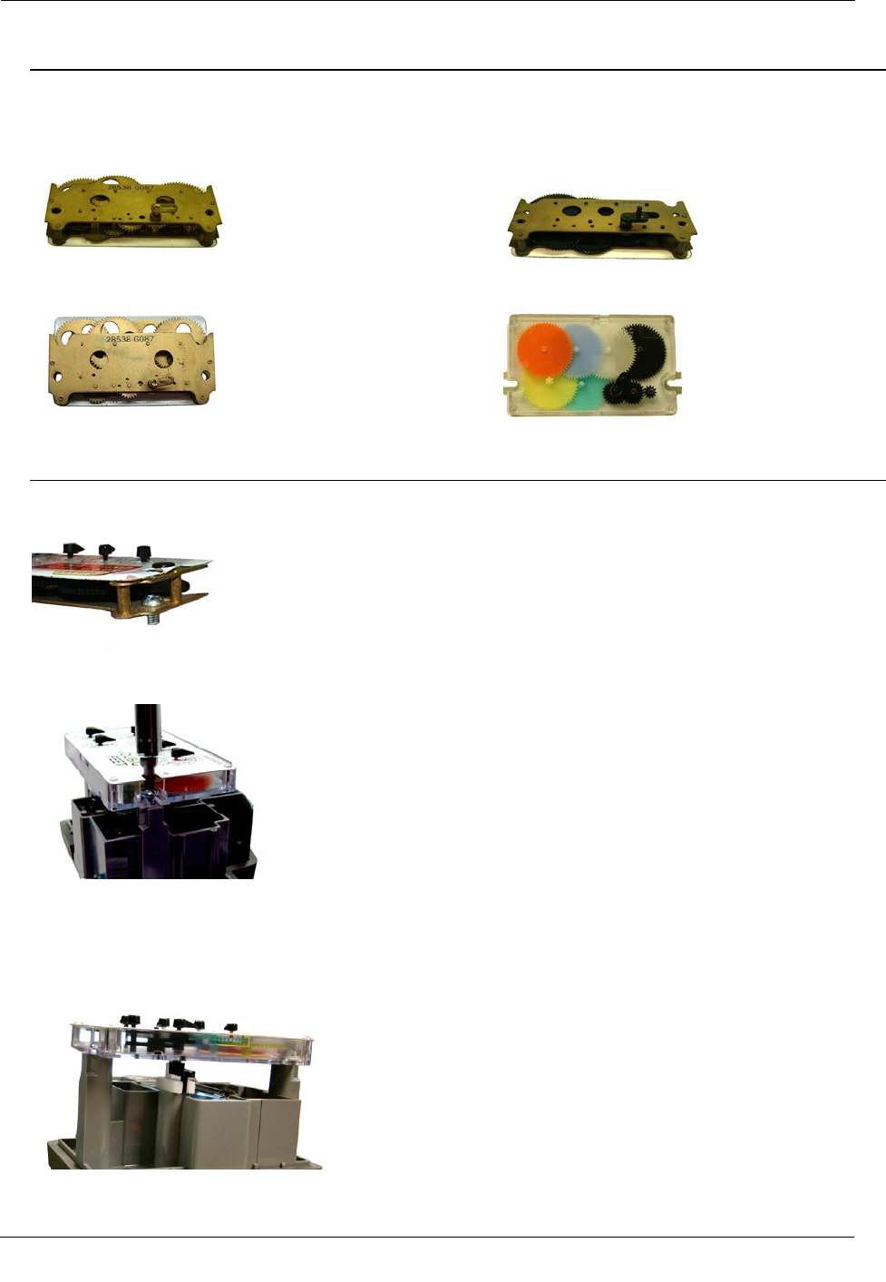
1. Separate the ERT module housing from the cover by pulling the cover straight out from the housing.
TDC-0823-014 100G Series Gas ERT Module Installation Guide, Direct Mount 18
Proprietary and Confidential
Elster American Meter Installation
2. Set the ERT module clear cover aside where it will not be damaged or fill with rain, dirt, or snow. You
will use the cover later in this installation procedure.
Note Elster American Meter indexes are available in different models:
Index wrigglers on one-foot meters with drive slots Index meters on two-foot meters with drive
posts
Index with mounting screw holes Index with mounting slots
If your index has mounting screw slots, skip steps 3 and 4. If your index has mounting screw holes,
perform steps 3 and 4, and skip steps 5 and 6.
3. Using the original index mounting screw or a replacement screw, if necessary, place one 8 - 32 3/16-inch
screw into the index's right-hand mounting screw hole.
4. Attach the screw to the ERT module housing's right-index mounting post just enough to hold the screw
and the right end of the index in place.
5. Screw one 8 - 32 x 3/16-inch screw into the right index mounting post loosely--one or two turns. Do not
tighten the screw.
6. Place the right index mounting screw slot under the screw head. Do not tighten the screw.
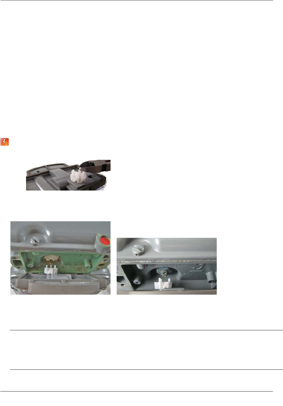
7. Slide the index drive post into the ERT module shaft slot. Verify positive engagement.
TDC-0823-014 100G Series Gas ERT Module Installation Guide, Direct Mount 19
Proprietary and Confidential
Elster American Meter Installation
Caution If the index wriggler has a drive slot, place the ERT shaft drive post into the index drive slot.
Failure to mate the ERT module shaft with the index drive post (or slot) can cause binding and lead to
poor registration or meter failure.
8. Install and tighten the left index mounting screw (for indexes with either mounting screw slots or holes).
Tighten the right index mounting screw. Install and tighten index mounting screws evenly.
9. Slide the ERT module cover over the index and housing. Verify the cover is installed correctly. The ERT
label should be clearly visible and easily read.
Programming the 100G ERT Module Assembly
Program the 100G, 100G DL, 100G DLN, or 100G DLT ERT modules using:
• An FC200SR handheld computer with Field Deployment Manager (FDM) software version 1.1 or higher
or
• A FC300 with SRead handheld computer with Field Deployment Manager (FDM) software version 1.1 or
higher
or
• A 900MHz Belt Clip Radio with Field Deployment Manager (FDM) software version 1.1 or higher and a
customer-supplied laptop. The Belt Clip Radio connects to the user-supplied laptop using a USB cable or
Bluetooth.
TDC-0823-014 100G Series Gas ERT Module Installation Guide, Direct Mount 20
Proprietary and Confidential
Elster American Meter Installation
The 100G DLS ERT modules support enhanced security with the Itron Security Manager. Enabling
command or enhanced security requires additional programming. Program the 100G DLS ERT modules
using:
• An FC200SR handheld computer with Field Deployment Manager (FDM) software version 3.3 or higher
or
• An FC300 with SRead handheld computer with Field Deployment Manager (FDM) software version 3.3
or higher
or
• A 900MHz Belt Clip Radio with Field Deployment Manager (FDM) software version 3.3 or higher and a
customer-supplied laptop. The Belt Clip Radio connects to the user-supplied laptop using a USB cable or
Bluetooth.
To enable enhanced security and for more complete programming information, see the Field Deployment
Manager Endpoint Tools Mobile Application Guide (TDC-0934).
FC200SR FC300 with SRead 900MHz Belt Clip Radio
Caution You must program the 100G ERT module before use.
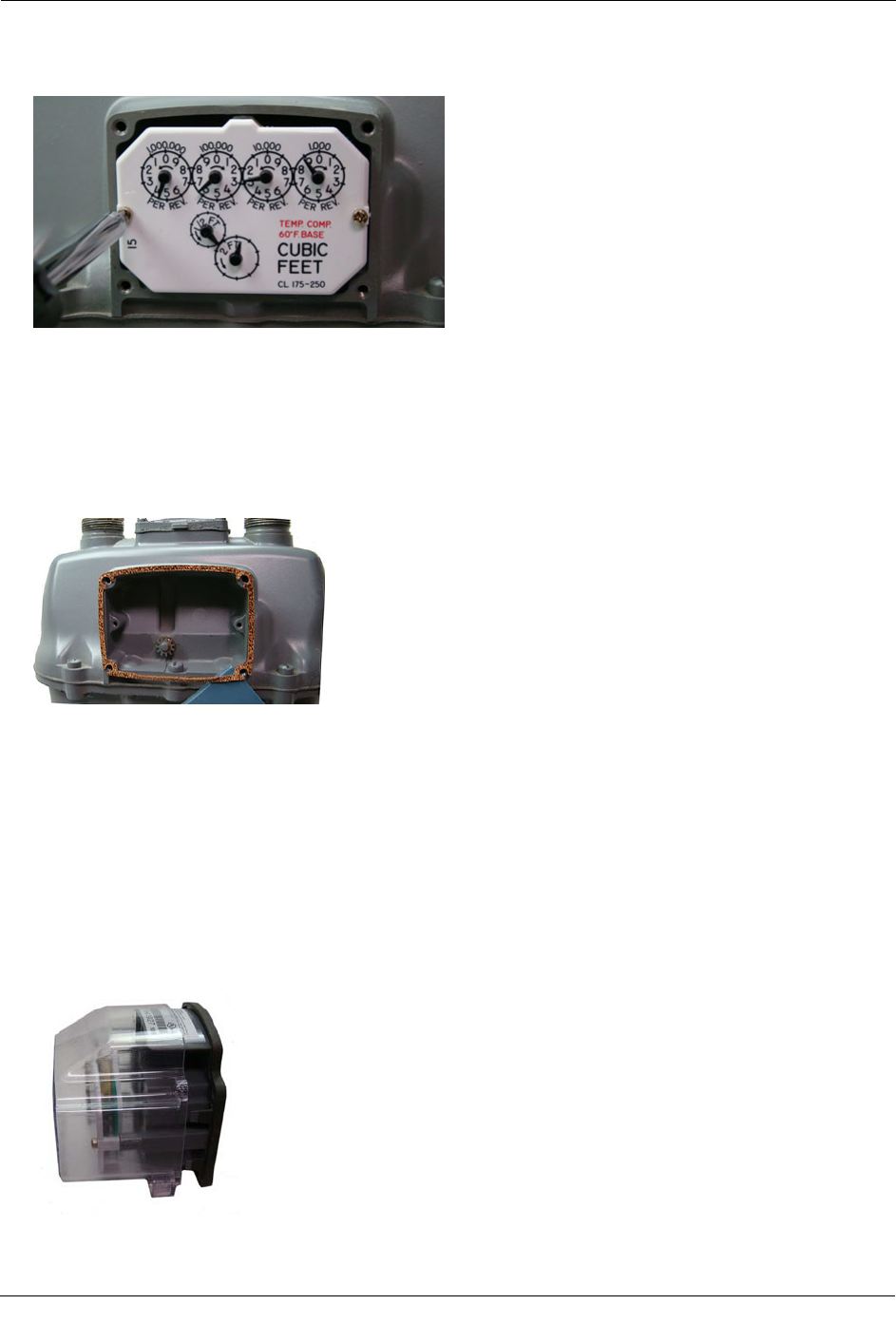
The ERT module is programmed based on the meter's drive rate. Take note of the index drive rate shown on a
lower dial on the index. Elster American meter index drive rates are either 1-cubic foot, 2-cubic feet or 0.05
cubic meters (not shown below).
TDC-0823-014 100G Series Gas ERT Module Installation Guide, Direct Mount 21
Proprietary and Confidential
Elster American Meter Installation
To program the ERT module assembly
1. Program the meter drive rate into the 100G series gas ERT module using the endpoint programming
device.
2. For all programming and Check Endpoint operations, hold the handheld programmer as close to vertical as
possible. For optimal results, keep the handheld programmer within 6 feet of the target ERT module.
3. Verify you have the correct programming mode (Fixed Network Mode, Mobile High Power Mode,
Mobile/Handheld Mode, or Hard to Read Mobile/Handheld Mode) for your application.
4. Programming parameters are based on the configuration file loaded into the ERT module programming
device. During programming, the 100G is set to the nearest 100 cubic feet; the last two digits (tens and
units) are programmed as zeros (0). After programming is complete, the ERT module assembly will read
to the nearest cubic foot.
Attaching the 100G ERT Module Assembly to the Meter
After you program the 100G, attach the ERT module assembly to the Elster American meter.
Warning For 5B-225 aluminum meters only: cut 1/16-inch off each ERT wriggler post to prevent
the wriggler from rubbing on the face of the nut holding the meter drive dog in place. Trimming the
drive post may make the module incompatible with other 2-ft. drive meters.
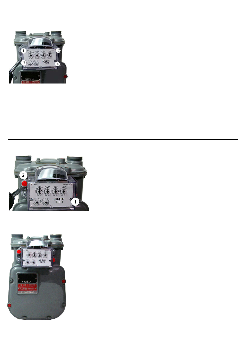
To attach the ERT module to the meter
1. Align the ERT wriggler to connect with the drive post (or slot) of the meter.
• For one-foot meters: Align the ERT assembly wriggler perpendicular to the meter drive post.
• For two-foot meters: Align the ERT assembly wriggler perpendicular to the meter drive slot. The pin
on the ERT wriggler may be installed inside or outside the meter drive slot. For easy assembly, Itron
recommends installing the pin on the 100G wriggler outside the meter drive slot.
Warning Failure to correctly align the meter drive post and ERT module drive slot can cause binding
and lead to poor registration or meter failure. If there is a gap between the ERT module gasket and the
meter, it may be the drive slot of the ERT module assembly's wriggler is not correctly aligned with the
meter drive slot. Remove the 100G assembly and repeat the alignment procedure. You must engage the
ERT module wriggler with the meter drive dog.
TDC-0823-014 100G Series Gas ERT Module Installation Guide, Direct Mount 22
Proprietary and Confidential
Elster American Meter Installation
2. Carefully align the ERT module's four screw holes with the holes on the meter. Attach the assembly using
the original mounting screws if they are the correct size and are not corroded (1/4 - 20 x 5/8-inch screws.)
If you discarded the original screws, use the correct replacement screws (see Installation Prerequisites on
page 14). Tighten the screws in an alternating, diagonal pattern as shown in the photo:
• Insert first screw and tighten 1/4 to 1/2 turn after the screw contacts the meter connection.
• Insert the second screw and tighten 1/4 to 1/2 turn after contact with the meter connection.
• Insert the third screw and tighten 1/4 to 1/2 turn after contact with the meter connection.
• Insert the last screw and tighten 1/4 to 1/2 turn after contact with the meter connection.
3. Return to the first screw and tighten. Continue with the second, third and last screw until all screws are
tight. Use equal screw tension to tighten each screw.
Important Meter manufacturers: torque the mounting screws 15 to 20 inch-pounds.
4. Place new tamper seals over the two screws with tamper seal mounts. Press tamper seals into place using
an 11/32-inch nut driver or similar blunt tool.
5. Complete necessary paperwork and verify all excess materials are removed from the customer premises.
100G series gas ERT module installation on the Elster American meter is complete.
TDC-0823-014 100G Series Gas ERT Module Installation Guide, Direct Mount 23
Proprietary and Confidential
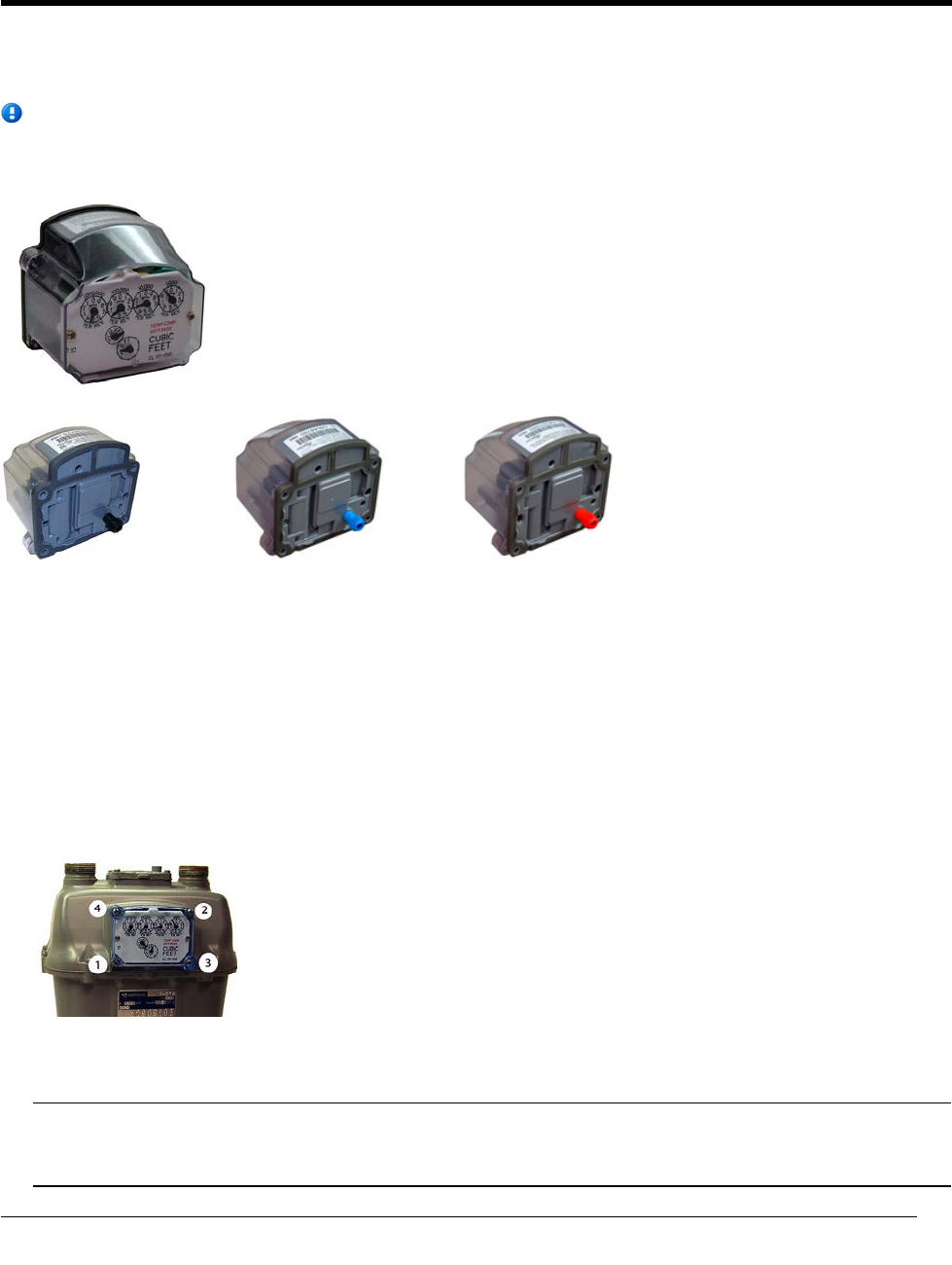
This chapter provides the instructions to install the ERT module on a Sensus meter. These instructions apply
to 11-tooth, 16-tooth, and 18-tooth Sensus 100G ERT modules.
Note Sensus meters are also known as Invensys, Equimeter, or Rockwell. For these instructions, all
meter types are referred to as Sensus meters.
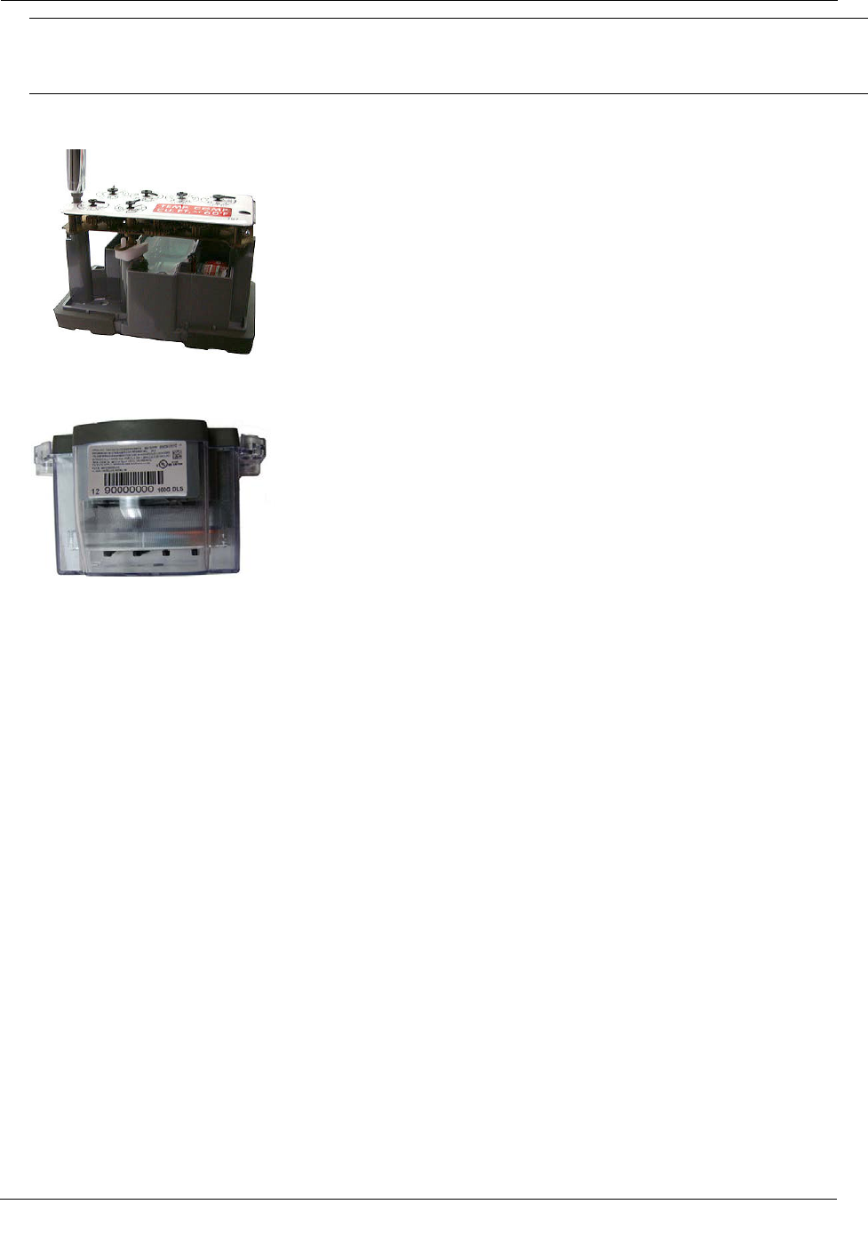
100G series gas ERT module
Sensus 11-tooth
Sensus 16-tooth
Sensus 18-tooth
Removing the Meter Index
Begin the module installation by removing the index cover and index from the meter.
To remove the index from the meter
1. Remove the four index cover screws and the index cover from the Sensus meter. Alternate screw removal
following the numbered pattern as shown in the following photo.
2. Examine the mounting screws. If they are 5/8-inch long and not corroded, keep them to attach the 100G
series gas ERT module assembly. If the screws are not the correct length or if the screws are corroded,
discard them.
Note You may use the removed index cover as a temporary storage container for screws. Properly
dispose all unused screws, old index covers, gaskets, tamper seals, and other leftover materials. Do not
leave materials on the customer premises.
CHAPTER 3
S
ensus Meter Installation
TDC-0823-014 100G Series Gas ERT Module Installation Guide, Direct Mount 24
Proprietary and Confidential
Sensus Meter Installation
3. Remove one index mounting screw completely. Hold one hand under the index to catch the screw. While
removing the other mounting screw, pull the index away from the meter to keep the index backplate
against the back of the screw. Remove the screw completely after the index is free of the meter.
4. Set the index aside where it will not be damaged or fill with dirt, rain, or snow. You will mount the index
in the ERT later in this procedure.
5. Verify the index mounting screws are 5/8-inch long and not corroded. If the screws are the correct length
and not corroded, retain for later use. If you discard the original screws, use the correct replacement
screws (see Installation Prerequisites on page 14.)
6. Remove the old gasket, gasket residue, and dirt from the meter (if applicable). The meter face must be free
of gasket residue or dirt before you install the 100G.
Assembling the Gas ERT Module and Index
Continue ERT module installation by assembling the ERT module and index.
To assemble the ERT module and index
1. Separate the ERT module housing from the clear cover by pulling the cover straight out from the housing.
Set the ERT module cover aside where it will not be damaged or fill with rain, dirt, or snow. You will
replace the cover later in this installation procedure.
TDC-0823-014 100G Series Gas ERT Module Installation Guide, Direct Mount 25
Proprietary and Confidential
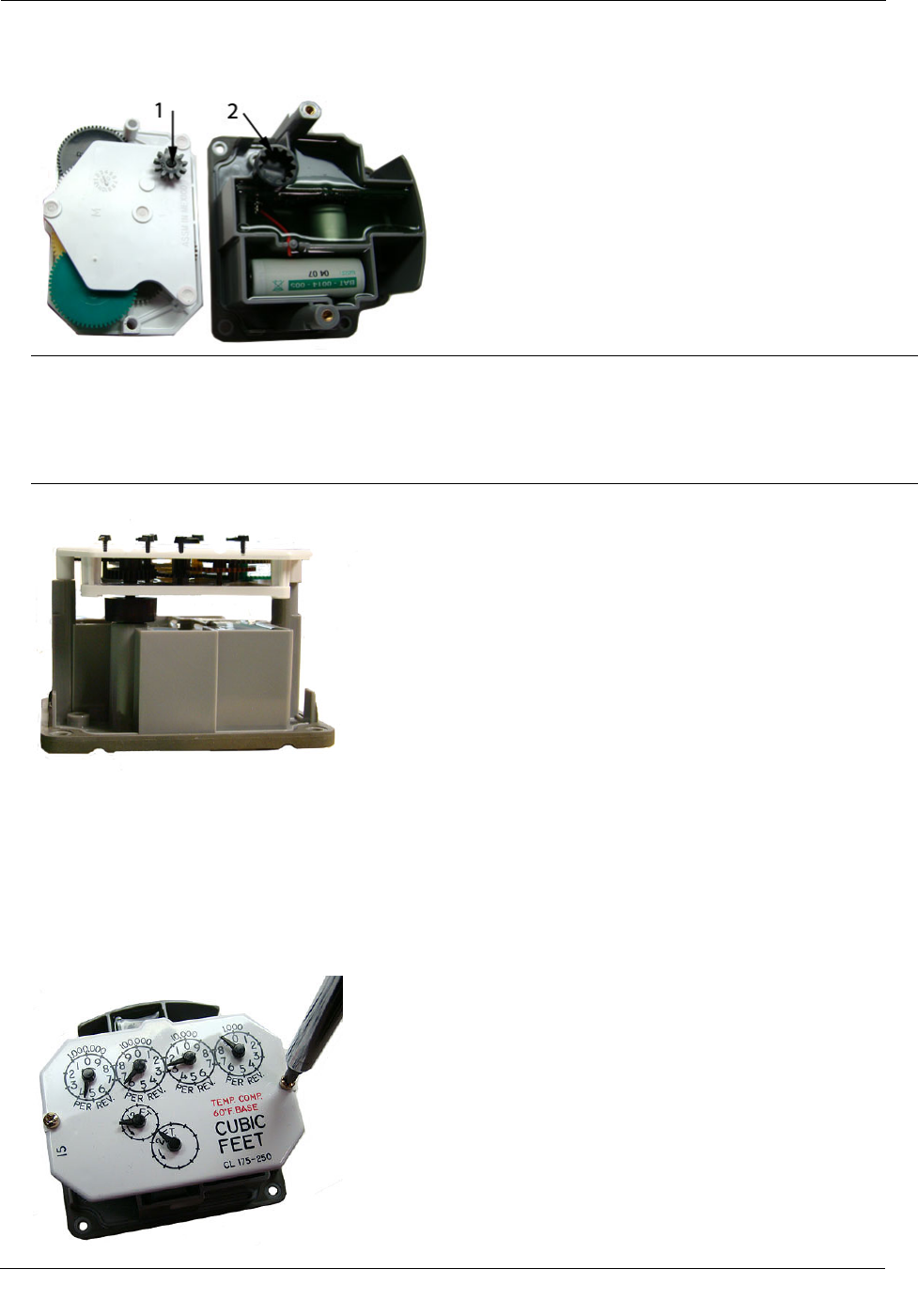
Sensus Meter Installation
2. Place the index drive gear (1) in the shaft gear cup (2) of the ERT. The example shows an 11-tooth drive
gear. Your index may be a 16- or 18-tooth gear. Use the appropriate ERT module for your specific meter.
See the 100G Gas ERT Module Meter Compatibility List for more information.
Warning Indexes have varying drive mechanism styles. Failure to align the 100G DLS shaft with the
index drive post can cause binding and lead to poor registration or meter failure. To verify proper
engagement of the index to the 100G ERT module shaft, spin the wriggler one clockwise rotation, then
one-counterclockwise rotation. Do not spin the shaft more than one complete rotation. The shaft should
spin freely, with little or no resistance.
3. After the index drive gear is aligned and inserted into the shaft gear cup, the mounting holes will line up.
4. Using the original index mounting screw or a replacement screw (if necessary), place one 6 - 32 x 5/8-inch
screw into the index right mounting screw hole.
5. Attach the screw to the ERT housing right-index mounting post just enough to hold the screw and the
right end of the index in place.
6. Install and tighten the left index mounting screw.
7. Tighten the right index mounting screw completely. Install and tighten both index mounting screws
evenly.
TDC-0823-014 100G Series Gas ERT Module Installation Guide, Direct Mount 26
Proprietary and Confidential
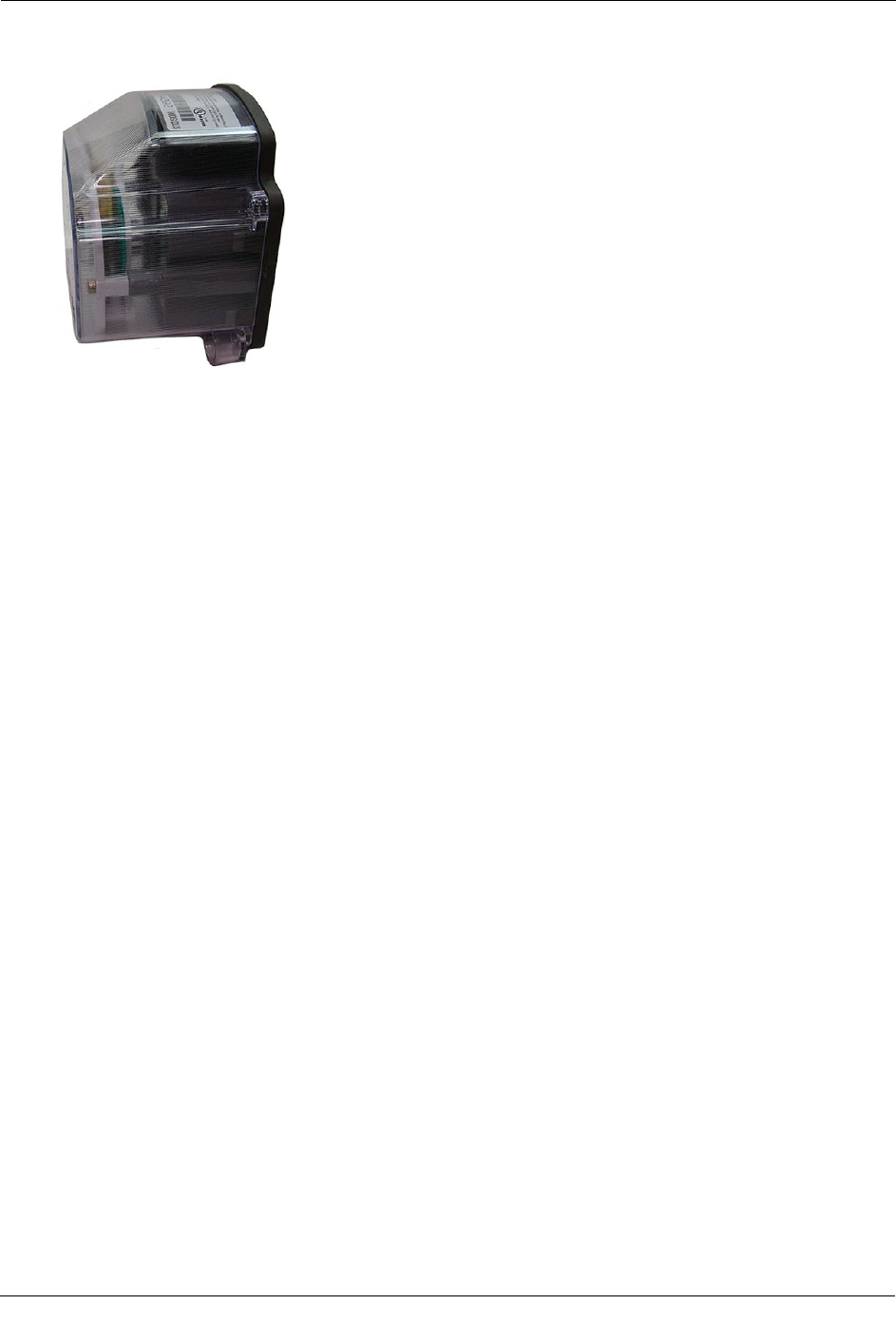
Sensus Meter Installation
8. Slide the ERT cover over the index and housing. Verify the cover is installed correctly. The ERT label
should be clearly visible and easily read.
Programming the 100G Gas ERT Module Assembly
Program the 100G, 100G DL, 100G DLN, or 100G DLT ERT modules using:
• An FC200SR handheld computer with Field Deployment Manager (FDM) software version 1.1 or higher
or
• A FC300 with SRead handheld computer with Field Deployment Manager (FDM) software version 1.1 or
higher
or
• A 900MHz Belt Clip Radio with Field Deployment Manager (FDM) software version 1.1 or higher and a
customer-supplied laptop. The Belt Clip Radio connects to the user-supplied laptop using a USB cable or
Bluetooth.
The 100G DLS ERT modules support enhanced security with the Itron Security Manager. Enabling
command or enhanced security requires additional programming. Program the 100G DLS ERT modules
using:
• An FC200SR handheld computer with Field Deployment Manager (FDM) software version 3.3 or higher
or
• An FC300 with SRead handheld computer with Field Deployment Manager (FDM) software version 3.3
or higher
or
• A 900MHz Belt Clip Radio with Field Deployment Manager (FDM) software version 3.3 or higher and a
customer-supplied laptop. The Belt Clip Radio connects to the user-supplied laptop using a USB cable or
Bluetooth.See the Field Deployment Manager Endpoint Tools Mobile Application Guide (TDC-0934) for
more complete programming information.
TDC-0823-014 100G Series Gas ERT Module Installation Guide, Direct Mount 27
Proprietary and Confidential
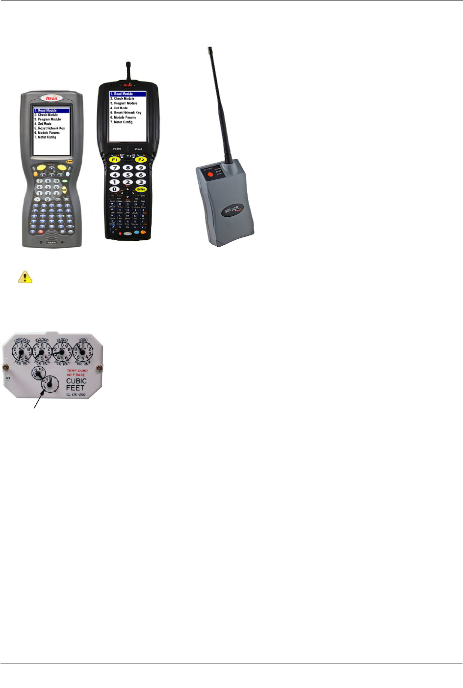
Sensus Meter Installation
To enable enhanced security and for more complete programming information, see the Field Deployment
Manager Endpoint Tools Mobile Application Guide (TDC-0934).
FC200SR FC300 with SRead 900MHz Belt Clip Radio
Caution You must program the 100G ERT module before use.
The ERT is programmed based on the meter's drive rate. Take note of the index drive rate shown on a lower
dial on the index. Sensus meter index drive rates are typically 2-cubic feet.
To program the ERT module assembly
1. Program the meter drive rate into the 100G series gas ERT module using the endpoint programming
device.
2. For all programming and Check Endpoint operations, hold the handheld programmer as close to vertical as
possible. For optimal results, keep the handheld programmer within 6 feet of the target ERT module.
3. Verify you have the correct programming mode (Fixed Network Mode, Mobile High Power Mode,
Mobile/Handheld Mode, or Hard to Read Mobile/Handheld Mode) for your application.
4. Programming parameters are based on the configuration file loaded into the ERT module programming
device. During programming, the 100G is set to the nearest 100 cubic feet; the last two digits (tens and
units) are programmed as zeros (0). After programming is complete, the ERT module assembly will read
to the nearest cubic foot.
TDC-0823-014 100G Series Gas ERT Module Installation Guide, Direct Mount 28
Proprietary and Confidential
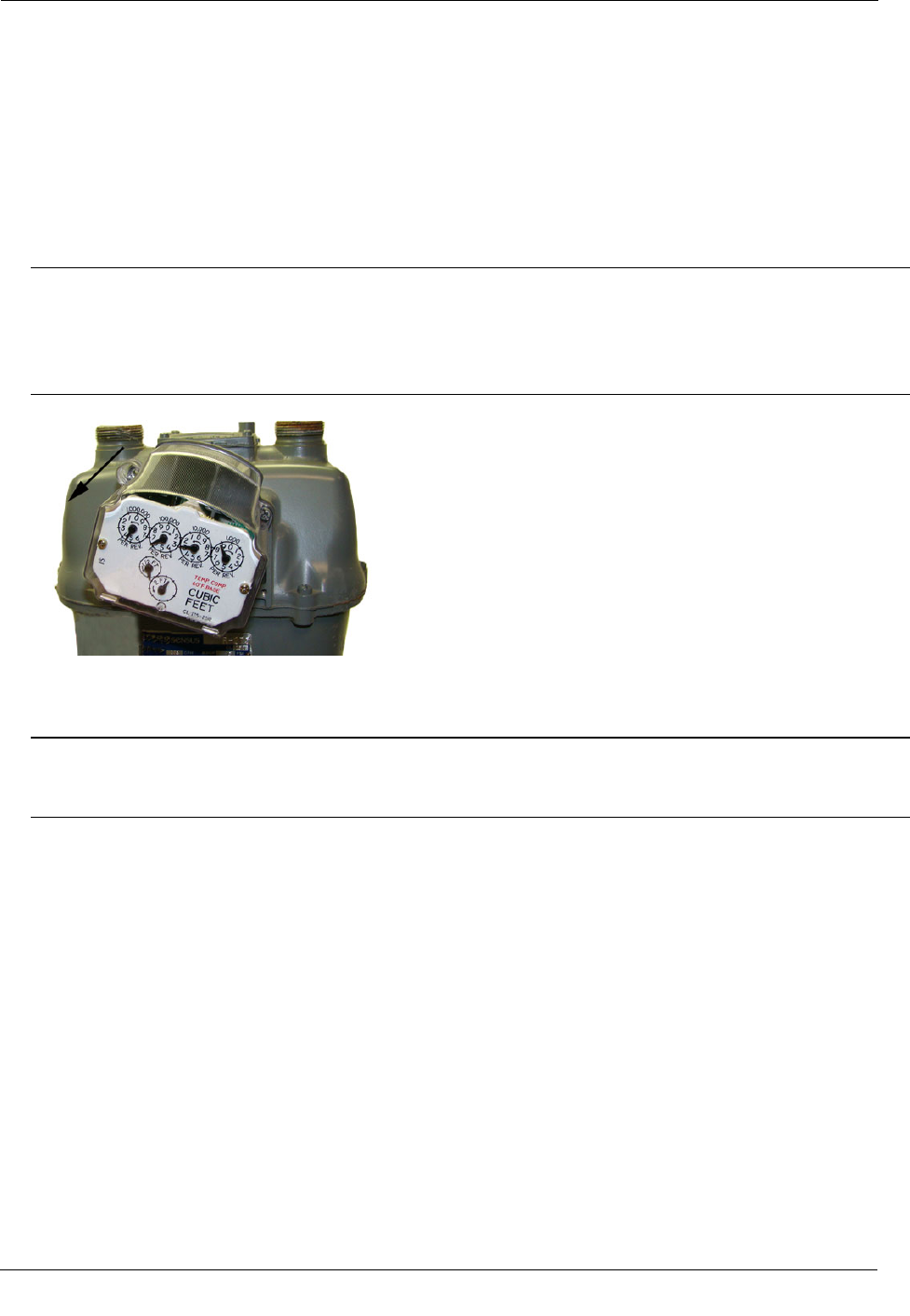
Sensus Meter Installation
Attaching the 100G Gas ERT Module Assembly to the Sensus
Meter
After 100G series gas ERT module programming is complete, attach the ERT module assembly to the Sensus
meter.
To attach the ERT module assembly to the meter
1. Place the ERT assembly against the front of the meter at angle.
Warning Failure to correctly align the meter drive gears and ERT module drive gears can cause binding
and lead to poor registration or meter failure. If there is a gap between the ERT module gasket and the
meter, it may be the drive gears of the ERT module assembly's wriggler are not correctly aligned with the
meter drive gears. Remove the 100G assembly and repeat the alignment procedure. You must engage
ERT module wriggler with the meter drive gears.
2. Install and tighten the ERT-to-meter mounting screws in an alternating pattern. Use the original mounting
screws if they were the correct size and not corroded. If you discarded the original screws, use the correct
replacement screws (see Installation Prerequisites on page 14).
Caution As the ERT module assembly is secured into its final position on the meter, shifting may occur
due to existing tolerances within the mounting screw holes. To ensure full ERT wriggler gear to meter
gear engagement, push the ERT module to the right while tightening the screws in the following pattern.
• Align the top right mounting screw hole on the meter with the top right screw hole on the ERT
module.
• Insert the top right cover mounting screw and tighten the screw enough to hold the ERT module
assembly in place. Do not completely tighten the screw.
• Rotate the ERT module assembly counterclockwise until the remaining three ERT screw holes line up
with the holes in the meter.
TDC-0823-014 100G Series Gas ERT Module Installation Guide, Direct Mount 29
Proprietary and Confidential
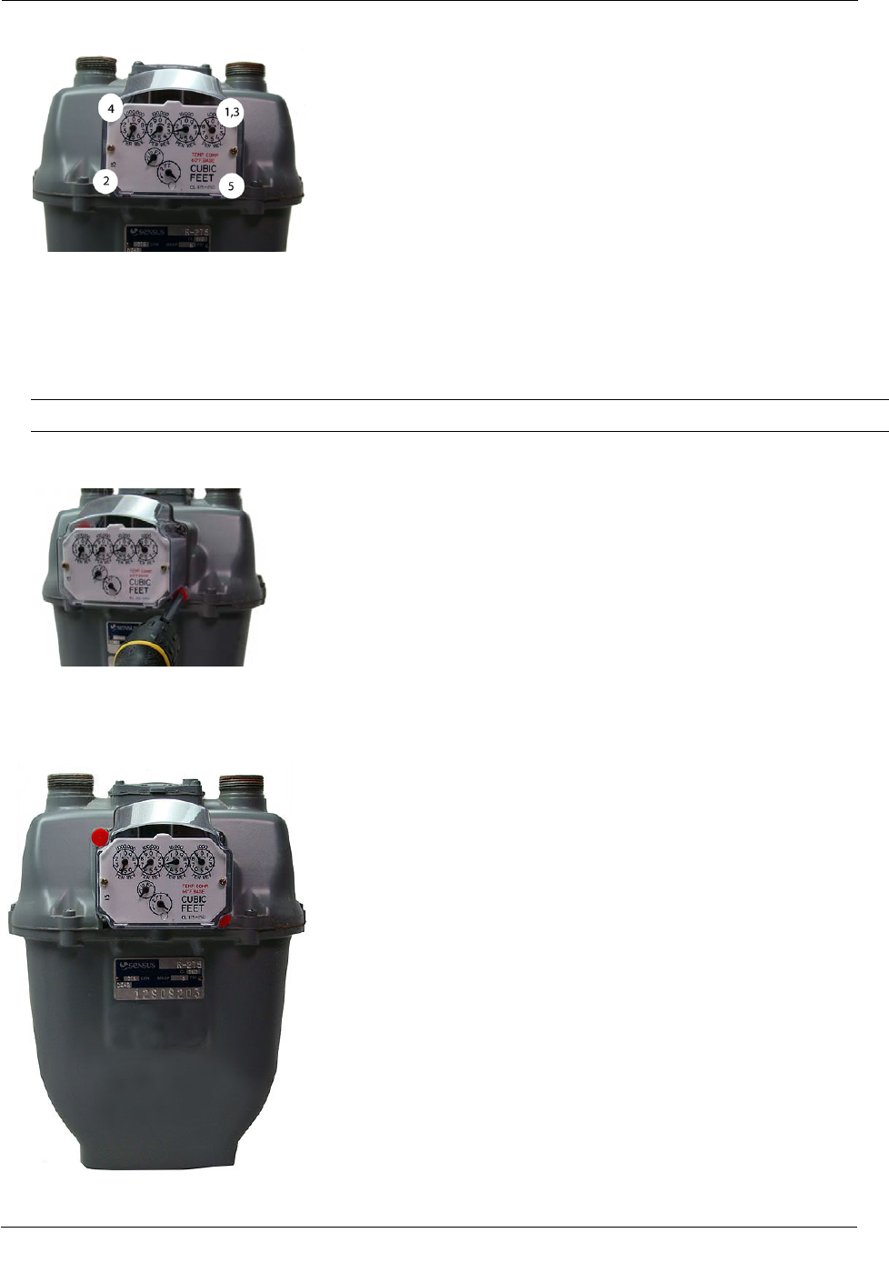
Sensus Meter Installation
3. Install the remaining three mounting screws and tighten in the pattern shown in the following illustration.
2. Insert lower left mounting screw (2) and tighten to snug position.
3. Tighten upper right mounting screw (1,3) to snug position.
4. Insert upper left mounting screw (4) and tighten to snug position.
5. Insert lower right mounting screw (5) and tighten to snug position.
Tighten each mounting screw evenly.
Important Meter manufacturers: torque the mounting screws 15 to 20 inch-pounds.
4. Place a new tamper seal over the two screws with tamper seal cups. Press the new tamper seals into place
using an 11/32-inch nut driver (or similar blunt tool).
5. Complete any necessary paperwork and properly dispose excess installation materials and scrap from the
customer premises.
100G series gas ERT module installation on the Sensus meter is complete.
TDC-0823-014 100G Series Gas ERT Module Installation Guide, Direct Mount 30
Proprietary and Confidential
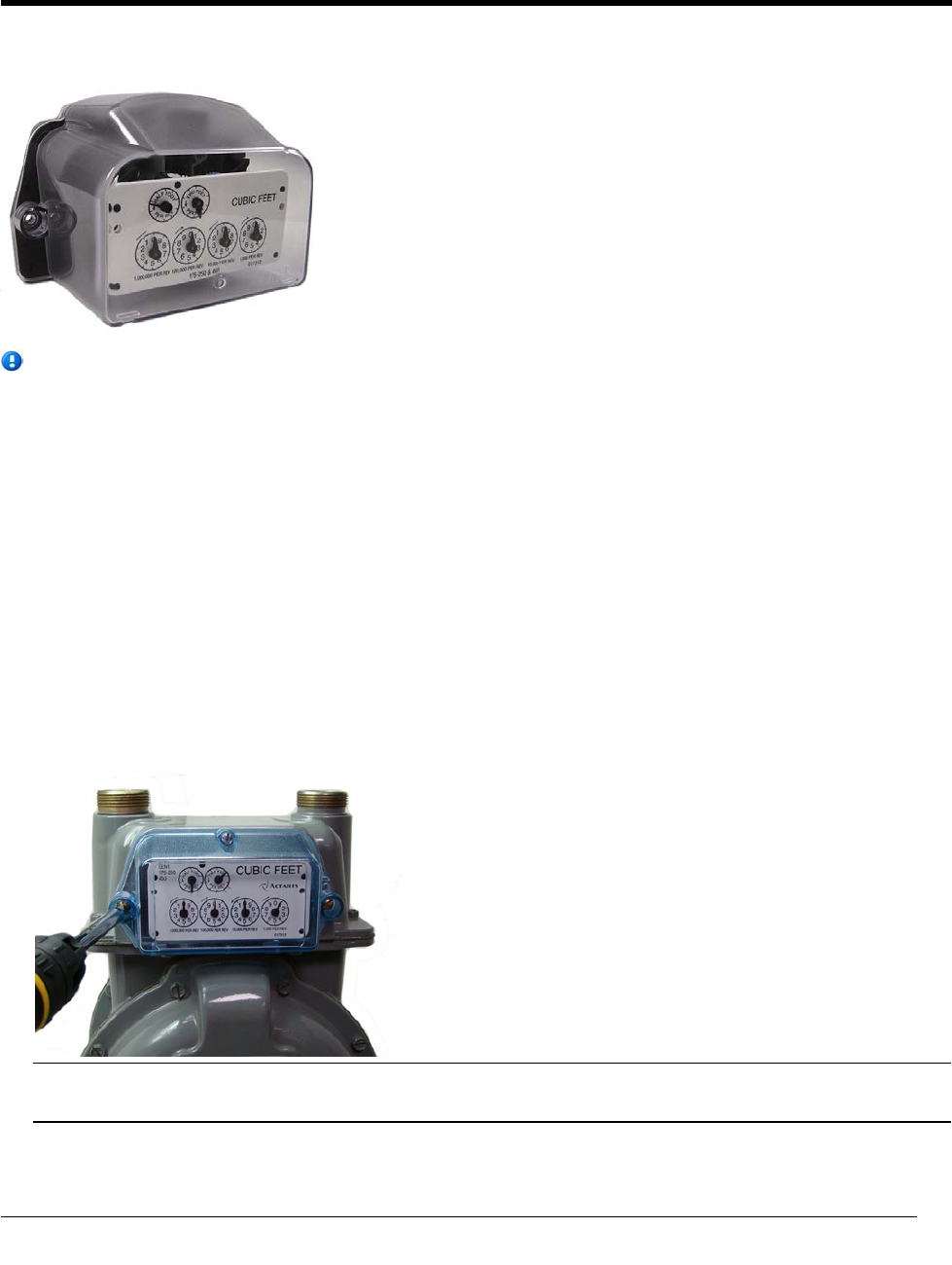
This chapter provides the instructions to install the ERT module on an Itron meter.
Note Itron meters are also known as Actaris, Schlumberger, or Sprague meters. For these
instructions, all meters will be referred to as Itron meters.
Removing the Meter Index
Begin the module installation by removing the index cover and index from the meter.
To remove the index from the meter
1. Remove the index cover screws and the index cover from the Itron meter. Examine the mounting screws.
If they are 5/8-inch long and not corroded, keep them to re-attach the 100G assembly. If the screws are not
the correct length or if the screws are corroded, discard them.
Note Use the removed index cover as a temporary storage container for the screws. Properly dispose all
unused screws, old index covers, gaskets, tamper seals, and other leftover materials.
CHAPTER 4
I
tron Meter Installation
TDC-0823-014 100G Series Gas ERT Module Installation Guide, Direct Mount 31
Proprietary and Confidential
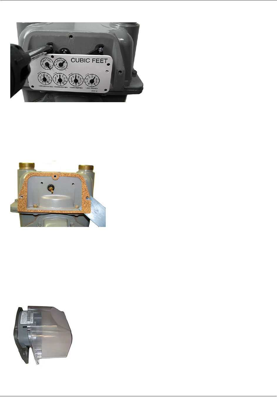
Itron Meter Installation
2. Loosen the index mounting screws 1/2 to one turn. Slide the index to the left and off the mounting screws.
Remove the index from the meter.
3. Set the index aside where it will not be damaged or fill with dirt, rain, or snow. You will mount the index
to the ERT module later in this procedure.
4. Verify the index mounting screws are 1/4-inch long and not corroded. If the screws are the correct length
and not corroded, retain for later use. If you discard the original screws, use the correct replacement
screws (see Installation Prerequisites on page 14).
5. Remove the old gasket, gasket residue, and dirt from the meter (if applicable). The meter face must be free
of gasket residue or dirt before you install the 100G.
Assembling the Gas ERT Module and Index
Continue ERT module installation by assembling the ERT module and index.
To assemble the ERT module and index
1. Separate the 100G housing from the cover by pulling the cover straight out from the housing. Set the ERT
cover aside where it will not be damaged or fill with rain, dirt or snow. You will use the cover later in this
installation procedure.
TDC-0823-014 100G Series Gas ERT Module Installation Guide, Direct Mount 32
Proprietary and Confidential
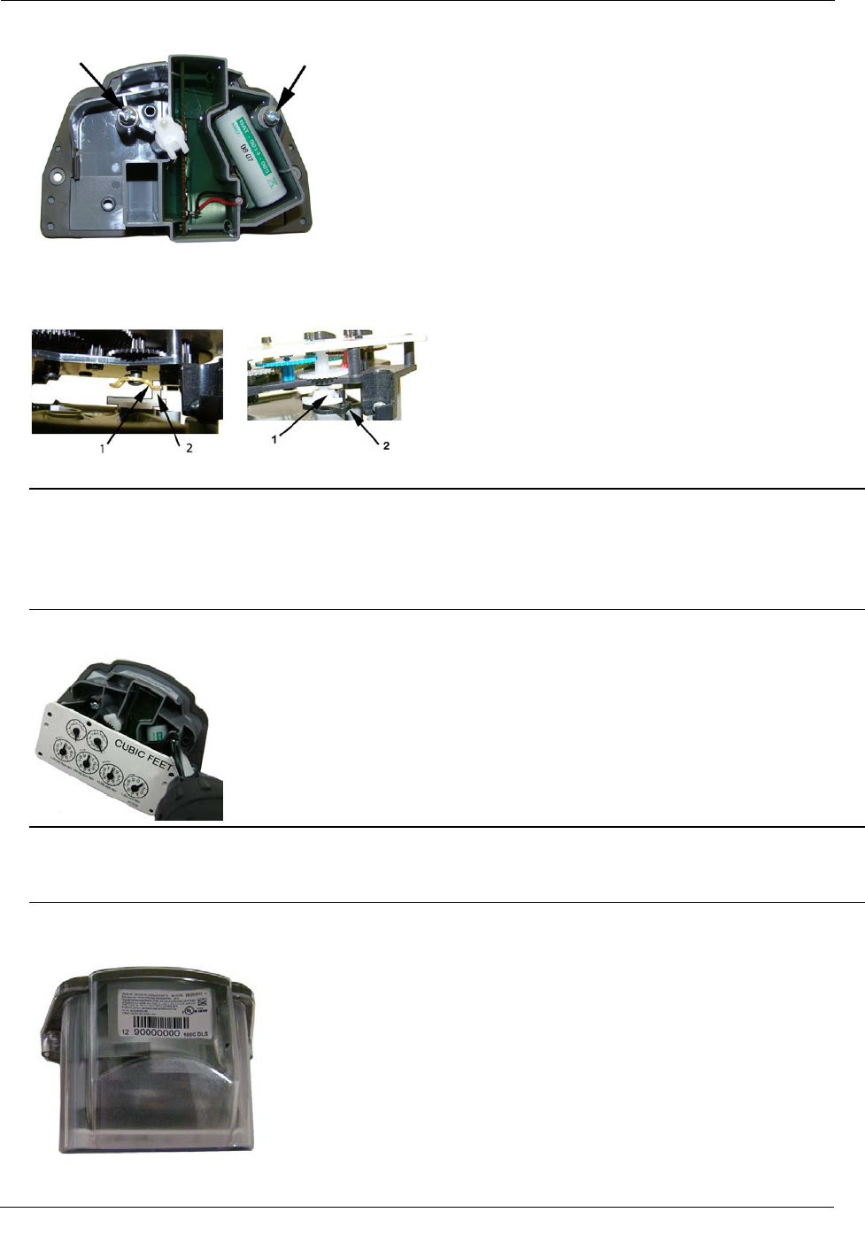
Itron Meter Installation
2. Insert the 10 - 24 x 1/4-inch screws into the index mounting posts two turns. Do not tighten the screws.
3. Align the index wriggler (1) with the drive post of the ERT shaft (2). Carefully slide the index onto the
mounting screws.
4. Verify the 100G shaft drive post makes positive engagement with the index wriggler.
Warning Indexes have varying drive mechanism styles. Failure to align the ERT shaft with the index
drive post can cause binding and lead to poor registration or meter failure. To verify proper engagement of
the index to the ERT shaft, spin the wriggler one clockwise rotation, then one-counterclockwise rotation.
Do not spin the wriggler more than one complete rotation. The wriggler should spin freely, with little or
no resistance.
5. Hold the index in place and tighten the index mounting screws.
Warning Verify the index is correctly positioned all the way to the right on the index mounting screws
before you tighten the index mounting screws. Failure to properly mount the index on the index mounting
screws may cause binding and meter failure.
6. Slide the ERT module cover over the index and housing. Verify the cover is installed correctly. The ERT
module label should be clearly visible and easily read.
TDC-0823-014 100G Series Gas ERT Module Installation Guide, Direct Mount 33
Proprietary and Confidential
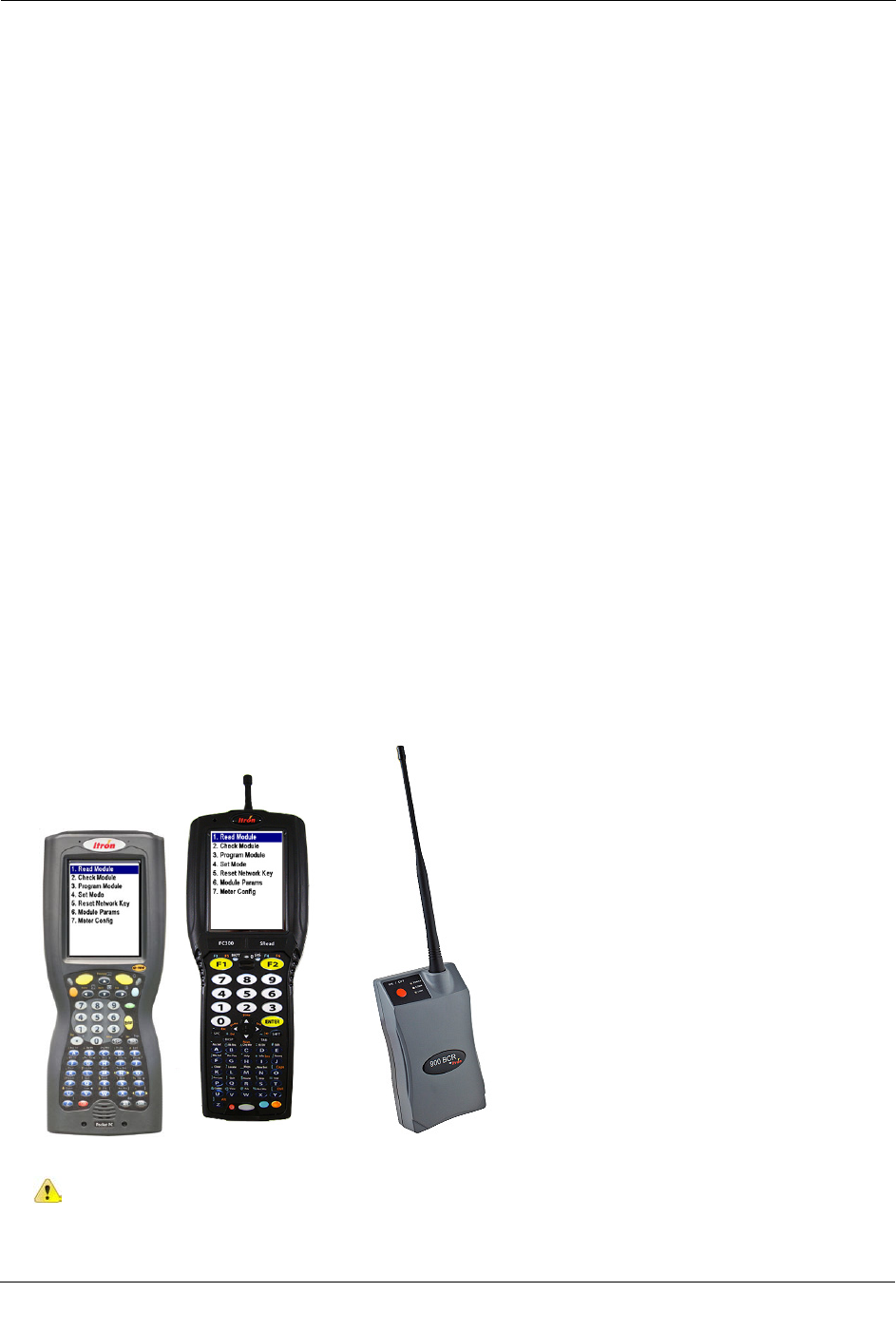
Itron Meter Installation
Programming the Itron ERT Module Assembly
Program the 100G, 100G DL, 100G DLN, or 100G DLT ERT modules using:
• An FC200SR handheld computer with Field Deployment Manager (FDM) software version 1.1 or higher
or
• A FC300 with SRead handheld computer with Field Deployment Manager (FDM) software version 1.1 or
higher
or
• A 900MHz Belt Clip Radio with Field Deployment Manager (FDM) software version 1.1 or higher and a
customer-supplied laptop. The Belt Clip Radio connects to the user-supplied laptop using a USB cable or
Bluetooth.
The 100G DLS ERT modules support enhanced security with the Itron Security Manager. Enabling
command or enhanced security requires additional programming. Program the 100G DLS ERT modules
using:
• An FC200SR handheld computer with Field Deployment Manager (FDM) software version 3.3 or higher
or
• An FC300 with SRead handheld computer with Field Deployment Manager (FDM) software version 3.3
or higher
or
• A 900MHz Belt Clip Radio with Field Deployment Manager (FDM) software version 3.3 or higher and a
customer-supplied laptop. The Belt Clip Radio connects to the user-supplied laptop using a USB cable or
Bluetooth.
To enable enhanced security and for more complete programming information, see the Field Deployment
Manager Endpoint Tools Mobile Application Guide (TDC-0934).
FC200SR FC300 with SRead 900MHz Belt Clip Radio
Caution You must program the ERT module before use.
TDC-0823-014 100G Series Gas ERT Module Installation Guide, Direct Mount 34
Proprietary and Confidential
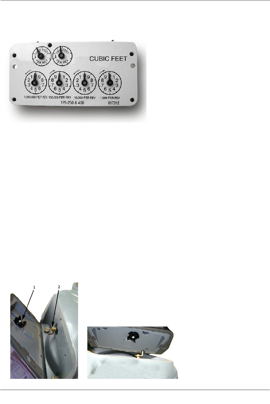
Itron Meter Installation
The ERT module is programmed based on the meter's drive rate. Take note of the index drive rate shown on
the drive dial on the index. The ERT is programmed based on the drive rate. Itron meter index drive rates are
typically 2-cubic feet.
To program the ERT module assembly
1. Program the meter drive rate into the 100G series gas ERT module using the endpoint programming
device.
2. For all programming and Check Endpoint operations, hold the handheld programmer as close to vertical as
possible. For optimal results, keep the handheld programmer within 6 feet of the target ERT module.
3. Verify you have the correct programming mode (Fixed Network Mode, Mobile High Power Mode,
Mobile/Handheld Mode, or Hard to Read Mobile/Handheld Mode) for your application.
4. Programming parameters are based on the configuration file loaded into the ERT module programming
device. During programming, the 100G is set to the nearest 100 cubic feet; the last two digits (tens and
units) are programmed as zeros (0). After programming is complete, the ERT module assembly will read
to the nearest cubic foot.
Attaching the ERT Module Assembly to the Itron Meter
After you program the ERT module, attach it to the Itron meter.
To attach the ERT module to the meter
1. Align the ERT so one of its four drive fins (1) lines up with the meter drive dog (2).
TDC-0823-014 100G Series Gas ERT Module Installation Guide, Direct Mount 35
Proprietary and Confidential
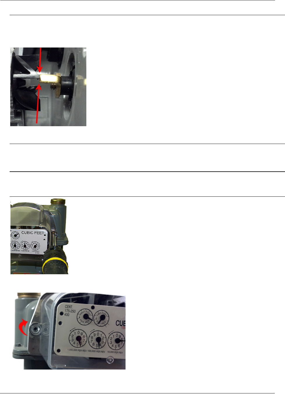
Itron Meter Installation
Warning Failure to correctly align the meter drive post and ERT module wriggler can cause binding and
lead to poor registration or meter failure. If there is a gap between the ERT module gasket and the meter,
it may be the wriggler of the ERT module is dead-headed against the meter drive dog as shown in the
following illustration.
Remove the 100G ERT module assembly and repeat the alignment procedure. You must engage the meter
drive post with the ERT module wriggler.
2. Place the 100G on the meter.
3. Insert the right module mounting screw and tighten the screw until the gasket is against the meter. Do not
completely tighten the mounting screw.
Note Use the original mounting screws to mount the 100G if they were the correct size and not corroded.
If you discarded the original screws, use the correct replacement screws (see Installation Prerequisites on
page 14.)
4. Slightly raise the left side of the ERT module (the module will rotate on the right screw) until the left ERT
module mounting hole is approximately 1/4-inch above the left meter mounting hole.
TDC-0823-014 100G Series Gas ERT Module Installation Guide, Direct Mount 36
Proprietary and Confidential
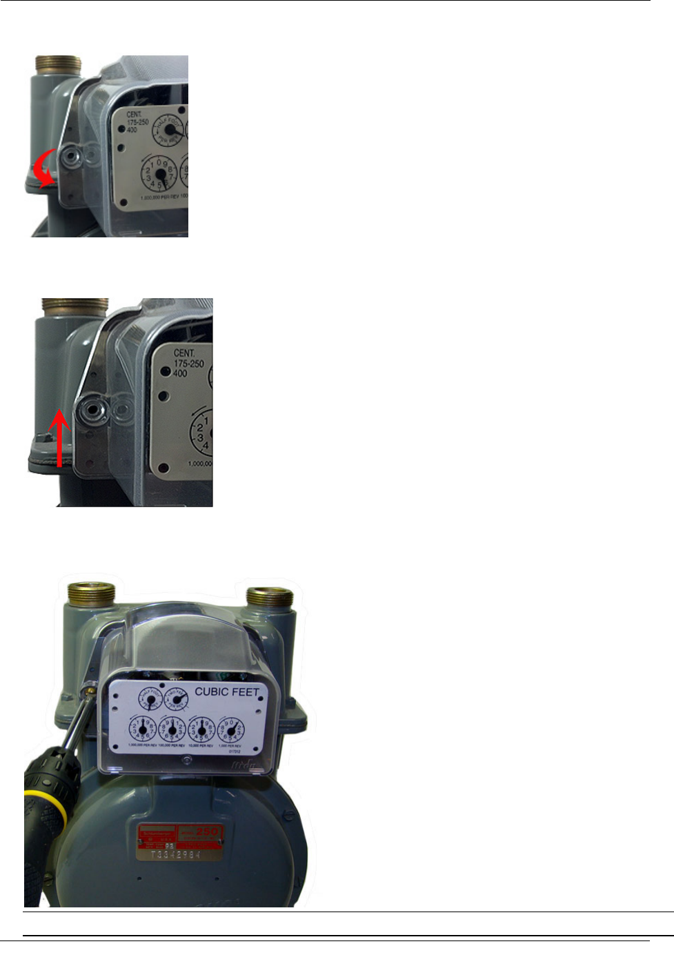
Itron Meter Installation
5. Rotate the ERT module down until the module mounting hole is approximately 1/4-inch below the meter
hole.
6. Rotate the ERT module up to align the left mounting holes. Raising and lowering the ERT module on the
meter drive post facilitates the proper positioning and engagement of ERT module wriggler with the meter
drive post.
7. Insert the left mounting screw and tighten a few turns.
8. Tighten the right and left ERT-to-meter mounting screws in an alternating pattern. Tighten each mounting
screw evenly.
Important Meter manufacturers: torque the mounting screws 15 to 20 inch-pounds.
TDC-0823-014 100G Series Gas ERT Module Installation Guide, Direct Mount 37
Proprietary and Confidential
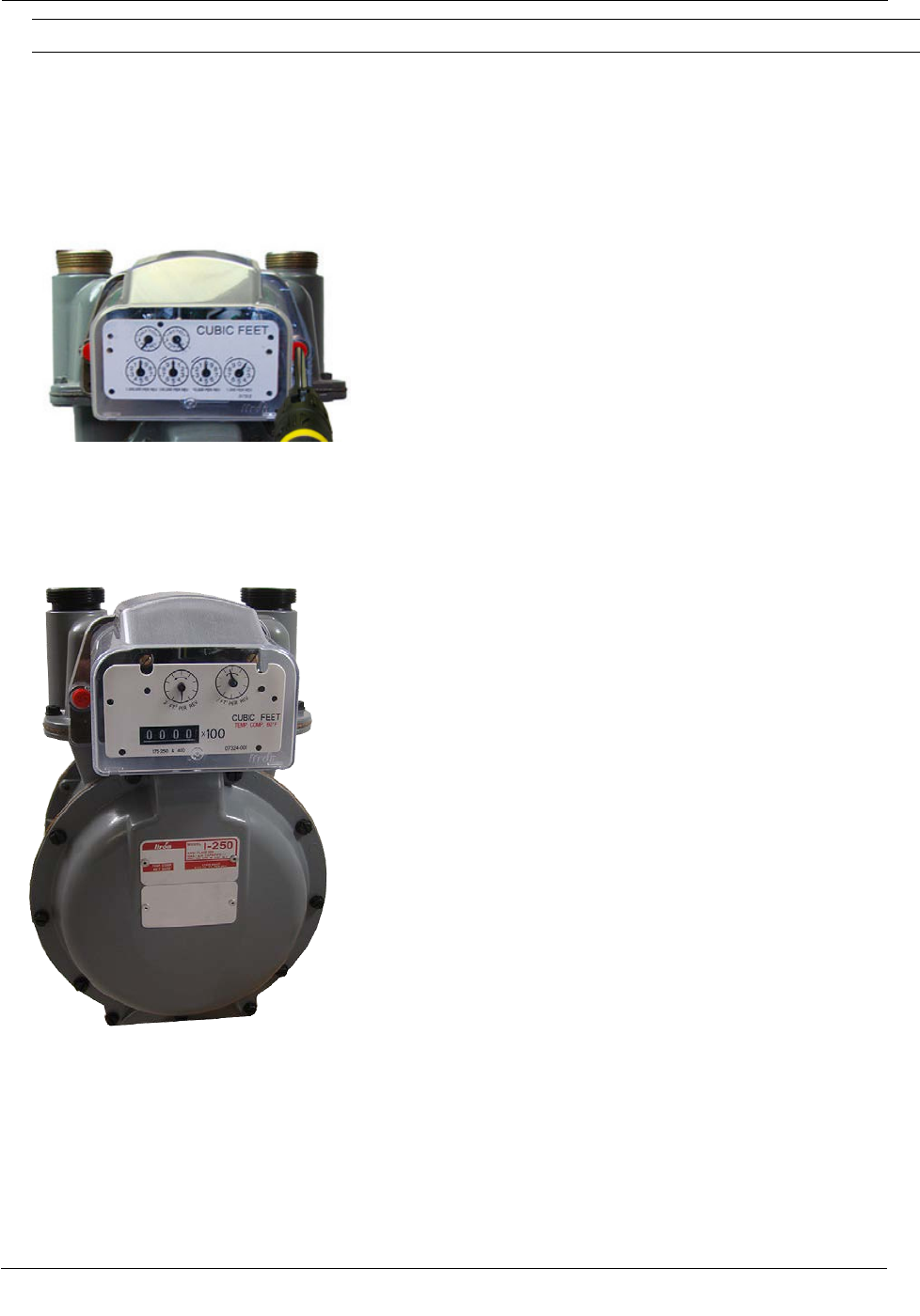
Itron Meter Installation
Tip The following conditions ensure proper engagement of the ERT module to the meter:
• The ERT module fits flush against the meter body--there are no gaps between the ERT gasket and the
meter body.
• The ERT module mounting holes align with the index cover mounting holes on the meter body.
• The meter test dial moves in relation to gas flowing through the meter.
9. Place a new tamper seal in the tamper seal cups surrounding the two mounting screws. Press the new
tamper seals into place using an 11/32-inch nut driver or similar blunt tool.
10. Complete any necessary paperwork and properly dispose excess installation materials and scrap from the
customer premises.
100G ERT module installation on the Itron meter is complete.
TDC-0823-014 100G Series Gas ERT Module Installation Guide, Direct Mount 38
Proprietary and Confidential
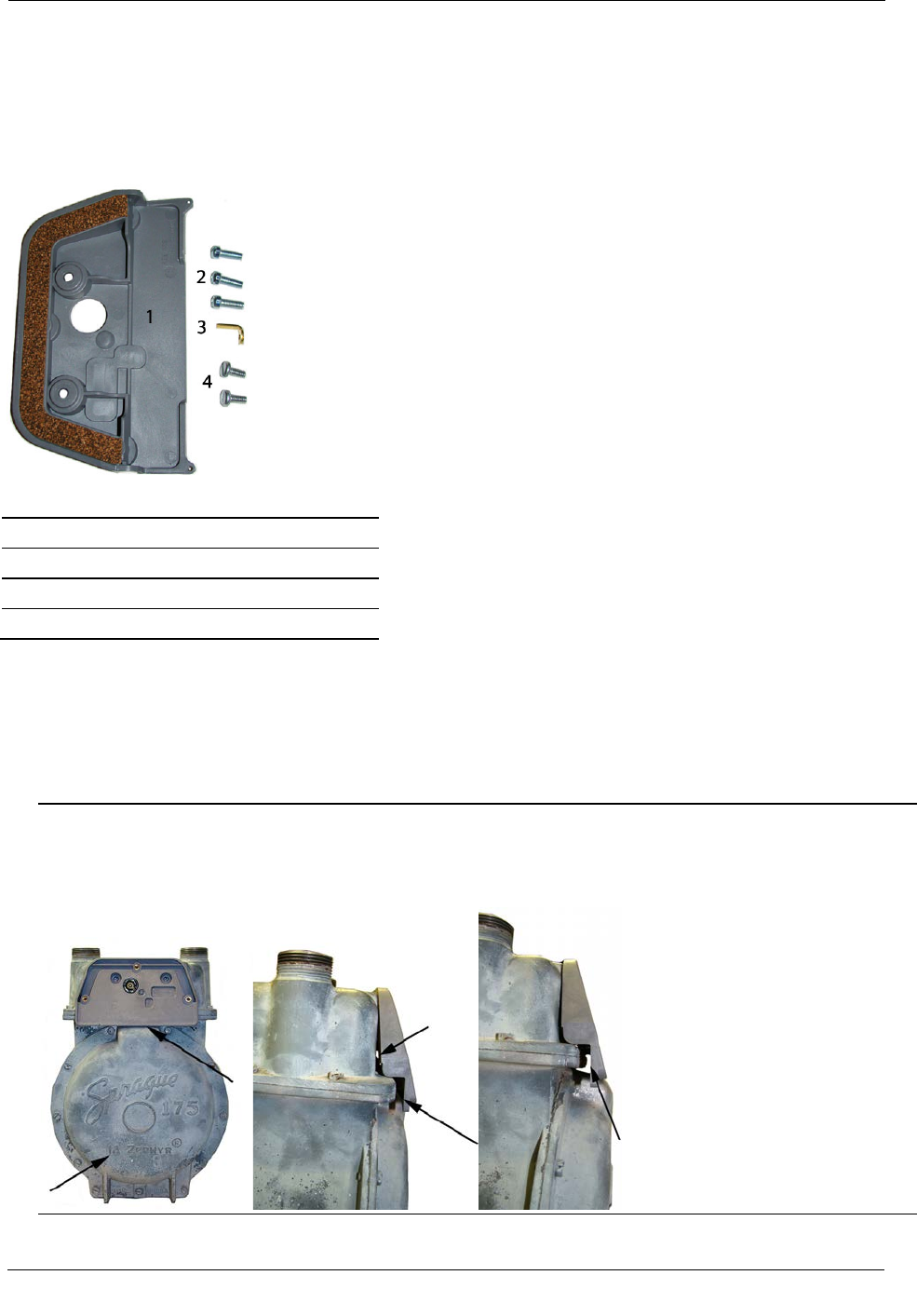
Itron Meter Installation
Attaching the ERT Module Assembly to Sprague Flat-faced
Meters
100G ERT module installation on a flat-faced Sprague meter requires the Itron Adapter Plate Kit (CFG-0015-
001).
Itron Adapter Plate Kit (CFG-0015-001)
1 Adapter Shim Plate
2 Index Cover Mounting Screws
3 Drive Dog
4 Adapter Plate Mounting Screws
To attach the ERT module assembly to the flat-faced Sprague meter
1. Verify the kit includes the materials listed in the Itron Adapter Plate Kit table.
Warning The adapter plate must fit flush against the meter face. Some older Sprague meters are not
compatible with the adapter plate. The following examples illustrate the potential obstruction (problem)
areas between the adapter plate and meter. Failure to mount the adapter plate flush on the front of a meter
could result in a binding condition and lead to poor registration or meter failure.
TDC-0823-014 100G Series Gas ERT Module Installation Guide, Direct Mount 39
Proprietary and Confidential
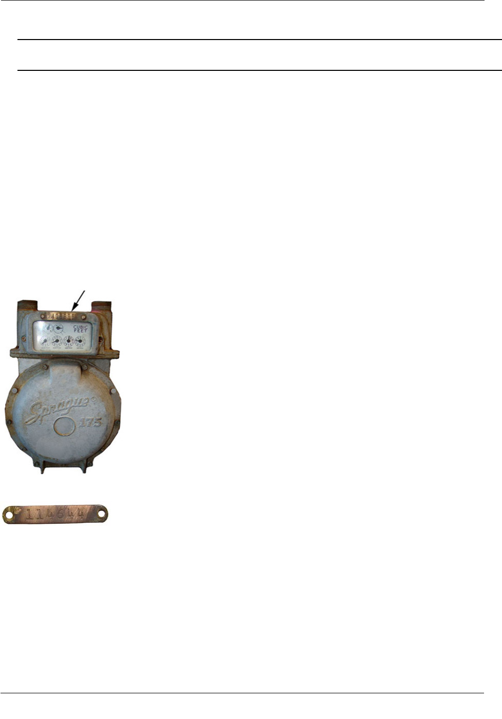
Itron Meter Installation
2. Remove the drive dog from the flat-faced Sprague meter. Replace it with the extended drive dog included
in the kit. Hand-tighten to snug.
Warning A gasket surrounds the meter drive dog shaft. A gas leak could result if the gasket is damaged.
Do not use a tool to install or tighten the new drive dog. Hand-tighten only.
• Attach the adapter plate to the meter with the gasket against the meter face. Secure the plate to the
meter with the two adapter plate mounting screws. Tighten the screws in an alternating pattern.
• Insert the right adapter plate screw and tighten the screw enough to hold it in place.
• Install the left mounting screw and tighten to a snug fit.
• Finish by tightening the right mounting screw to a snug fit.
Tighten each screw evenly.
Note The 100G must be assembled and programmed following the instructions in To assemble the ERT
module and index on page 32 and Programming the ERT Module Assembly on page 20 prior to installation on
the meter.
Securing Brass Meter Tags to Flat-faced Meters
Some older Sprague meters have metal index covers with brass meter tags attached (by screws or rivets) to
metal index covers.
Typically, brass meter tags have mounting (screw/rivet) holes on each end of the tag.
Mount brass meter tags using one of three Itron-approved methods.
To secure brass meter tags to flat-faced meters
Method 1 and 2
1. Carefully remove the brass meter tag from the meter index cover. Try not to damage the meter tag
mounting holes.
TDC-0823-014 100G Series Gas ERT Module Installation Guide, Direct Mount 40
Proprietary and Confidential
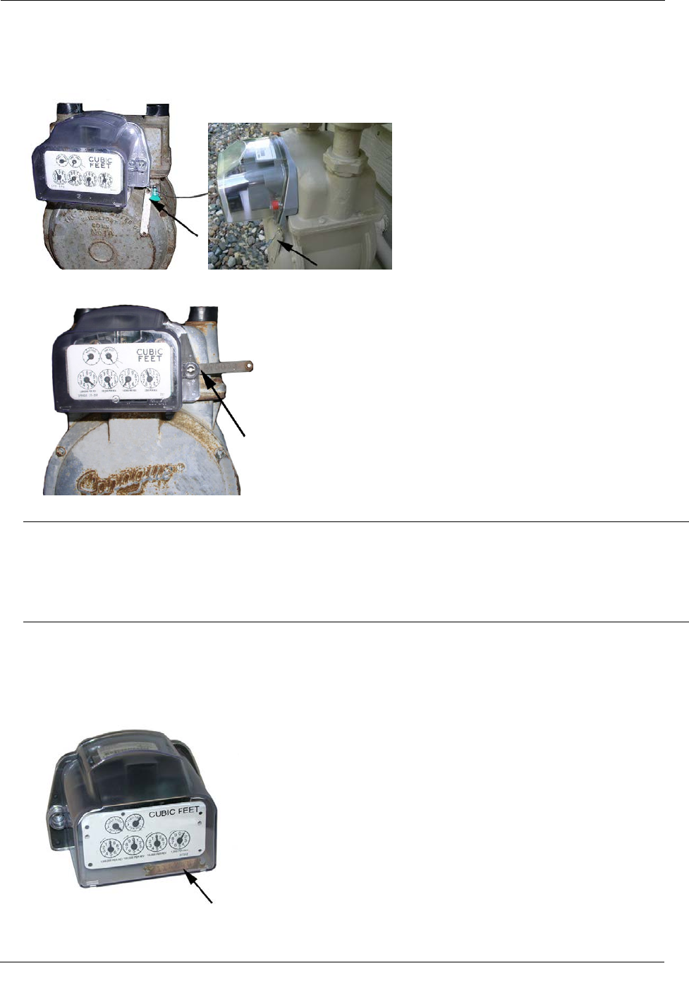
Itron Meter Installation
2. Attach the 100G assembly to the meter. The Sprague adapter plate has tag mounting holes in the lower left
and right corners. Secure the meter tag to one of the holes with a utility-approved and provided security
seal.
Method 1: Attach the meter tag to the adapter plate tag mounting hole
Method 2: Attach the meter tag to the 100G mounting hole
Note If the brass meter tag will be secured to the meter utilizing the ERT-to-meter mounting hole, it must
be attached during the 100G series gas ERT module installation procedure described in Step 1 of
Attaching the ERT Module Assembly on the Meter on page 35.
Caution A protruding brass meter tag can present a safety concern particularly if the tag is damaged with
sharp edges protruding from the meter.
Method 3
1. Remove the 100G index cover.
2. Place the meter tag inside the ERT assembly for optimal meter tag security. (See To assemble the ERT
module and index on page 32.)
Method 3: Place the brass meter tag inside the ERT module assembly
TDC-0823-014 100G Series Gas ERT Module Installation Guide, Direct Mount 41
Proprietary and Confidential
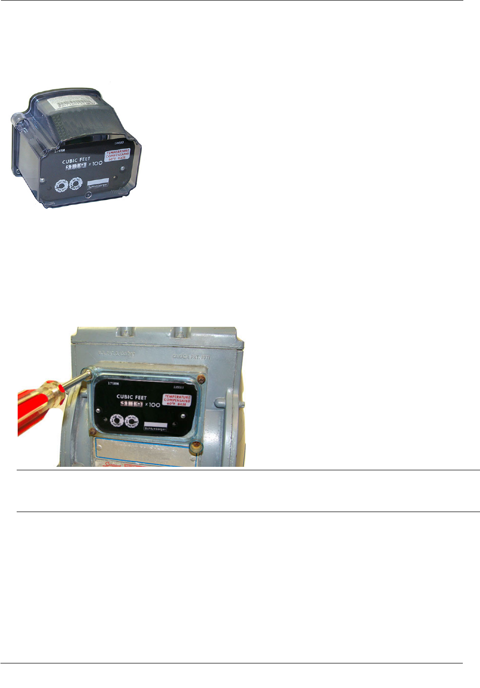
Itron Meter Installation
Attaching the ERT Module Assembly to a Sprague 175RM
Meters
This section provides the information to attach the 100G to a Sprague 175RM meter.
Removing the Meter Index
Begin the module installation by removing the index cover and index from the meter.
To remove the index from the meter
1. Remove the index cover mounting screws and the index cover from the Sprague 175RM meter. Discard
the index cover and index cover mounting screws.
Note The removed index cover may be used as a temporary refuse container for screws. Properly dispose
the index cover and all unused screws, gaskets, tamper seals, and other leftover materials. Do not leave
materials on customer premises.
2. Loosen the index mounting screws 1/2 to one turn. Slide the index up and off the mounting screws and
remove it from the meter. Set the index aside where it will not be damaged or fill with dirt, rain or snow.
You will mount the index in the module later in this procedure. Remove the index mounting screws from
the meter. Verify the index mounting screws are 1/4-inch long and not corroded. If the screws are the
correct length and not corroded, retain for later use. If the original screws are discarded, use the correct
replacement screws (see Installation Prerequisites on page 14).
TDC-0823-014 100G Series Gas ERT Module Installation Guide, Direct Mount 42
Proprietary and Confidential
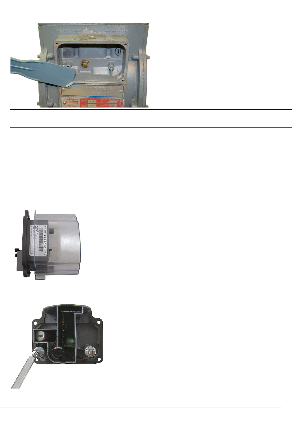
Itron Meter Installation
3. Remove the old gasket, gasket residue, and dirt from the meter (if applicable). The meter face must be free
of gasket residue or dirt before you install the 100G.
Note Properly dispose all unused screws, old index covers, gaskets, tamper seals, and other leftover
materials. Do not leave materials on customer premises.
Assembling the Gas ERT Module and Index
Continue ERT module installation by assembling the ERT module and index.
To assemble the 100G series gas ERT module and index
1. Separate the ERT module housing from the cover by pulling the cover straight out from the housing. Set
the module cover aside where it will not be damaged or fill with rain, dirt or snow. The cover is used later
in this installation procedure.
2. Screw the index mounting screws into the index mounting posts loosely (one to two turns). Do not tighten
the screws.
TDC-0823-014 100G Series Gas ERT Module Installation Guide, Direct Mount 43
Proprietary and Confidential
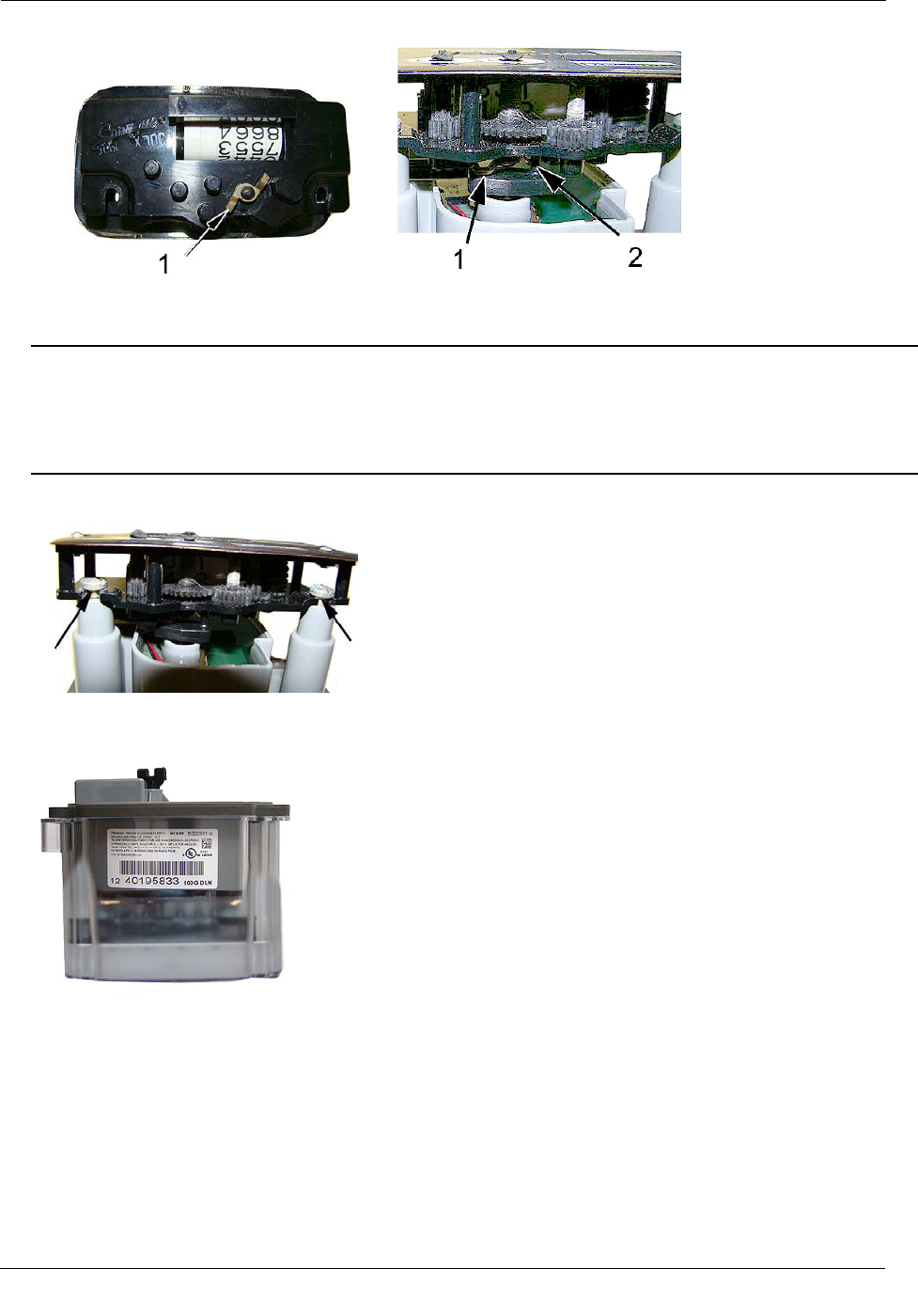
Itron Meter Installation
3. Align the index wriggler (1) with the ERT module drive post (shaft, 2).
4. Carefully slide the index onto the mounting screws. Verify the 100G housing drive post makes positive
engagement with the index wriggler.
Caution Indexes have varying drive mechanism styles. Failure to align the ERT shaft with the index
drive post can cause binding and lead to poor registration or meter failure. To verify proper engagement of
the index to the ERT shaft, spin the wriggler one clockwise rotation, then one-counterclockwise rotation.
Do not spin the wriggler more than one complete rotation. The wriggler should spin freely, with little or
no resistance.
5. Hold the index in place and tighten the index mounting screws.
6. Slide the ERT module cover over the index and housing. Verify the cover is installed correctly. The label
should be clearly visible and easily read.
TDC-0823-014 100G Series Gas ERT Module Installation Guide, Direct Mount 44
Proprietary and Confidential
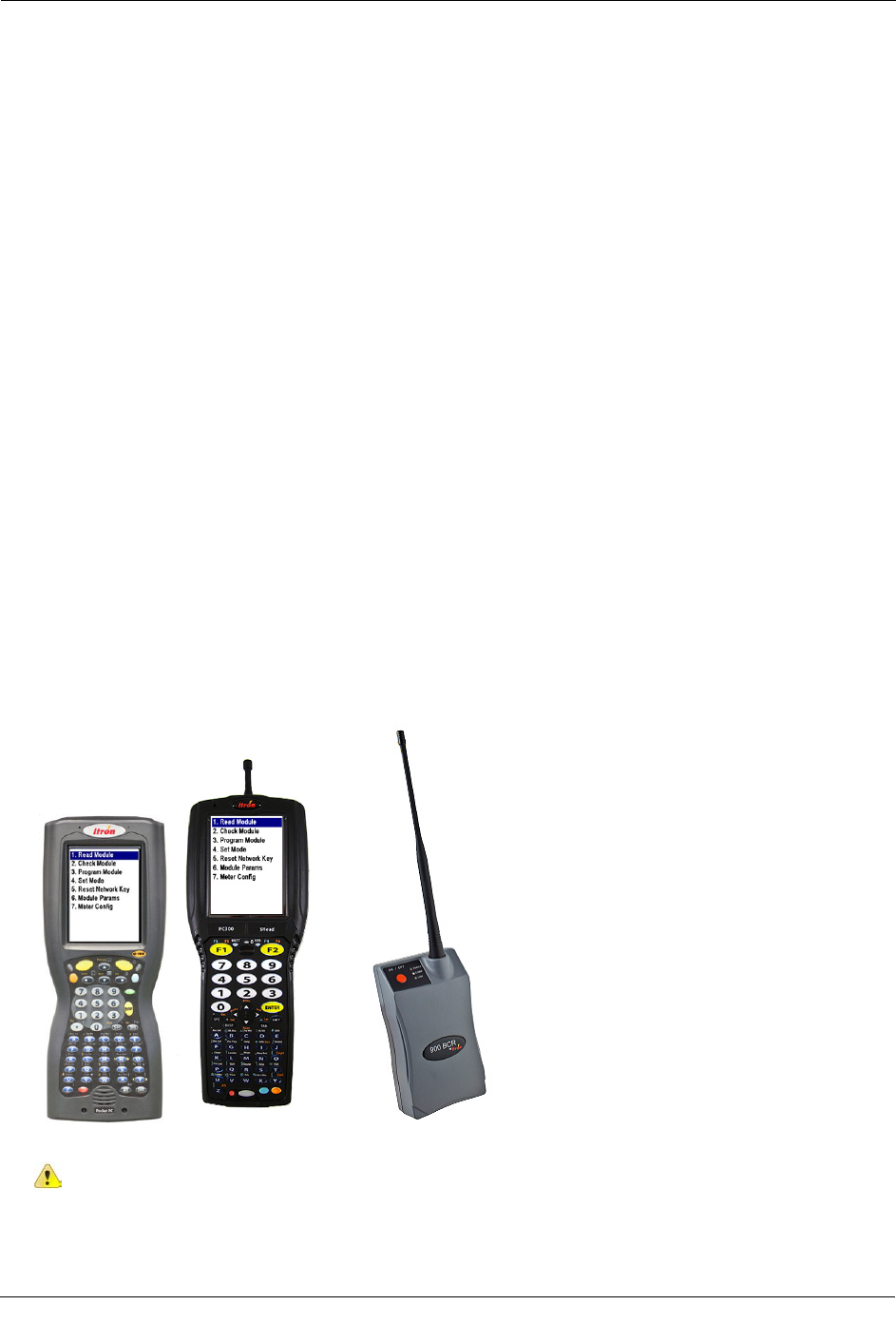
Itron Meter Installation
Programming the 100G ERT Module Assembly
Program the 100G, 100G DL, 100G DLN, or 100G DLT ERT modules using:
• An FC200SR handheld computer with Field Deployment Manager (FDM) software version 1.1 or higher
or
• A FC300 with SRead handheld computer with Field Deployment Manager (FDM) software version 1.1 or
higher
or
• A 900MHz Belt Clip Radio with Field Deployment Manager (FDM) software version 1.1 or higher and a
customer-supplied laptop. The Belt Clip Radio connects to the user-supplied laptop using a USB cable or
Bluetooth.
The 100G DLS ERT modules support enhanced security with the Itron Security Manager. Enabling
command or enhanced security requires additional programming. Program the 100G DLS ERT modules
using:
• An FC200SR handheld computer with Field Deployment Manager (FDM) software version 3.3 or higher
or
• An FC300 with SRead handheld computer with Field Deployment Manager (FDM) software version 3.3
or higher
or
• A 900MHz Belt Clip Radio with Field Deployment Manager (FDM) software version 3.3 or higher and a
customer-supplied laptop. The Belt Clip Radio connects to the user-supplied laptop using a USB cable or
Bluetooth.
To enable enhanced security and for more complete programming information, see the Field Deployment
Manager Endpoint Tools Mobile Application Guide (TDC-0934).
FC200SR FC300 with SRead 900MHz Belt Clip Radio
Caution You must program the 100G ERT module before use.
TDC-0823-014 100G Series Gas ERT Module Installation Guide, Direct Mount 45
Proprietary and Confidential
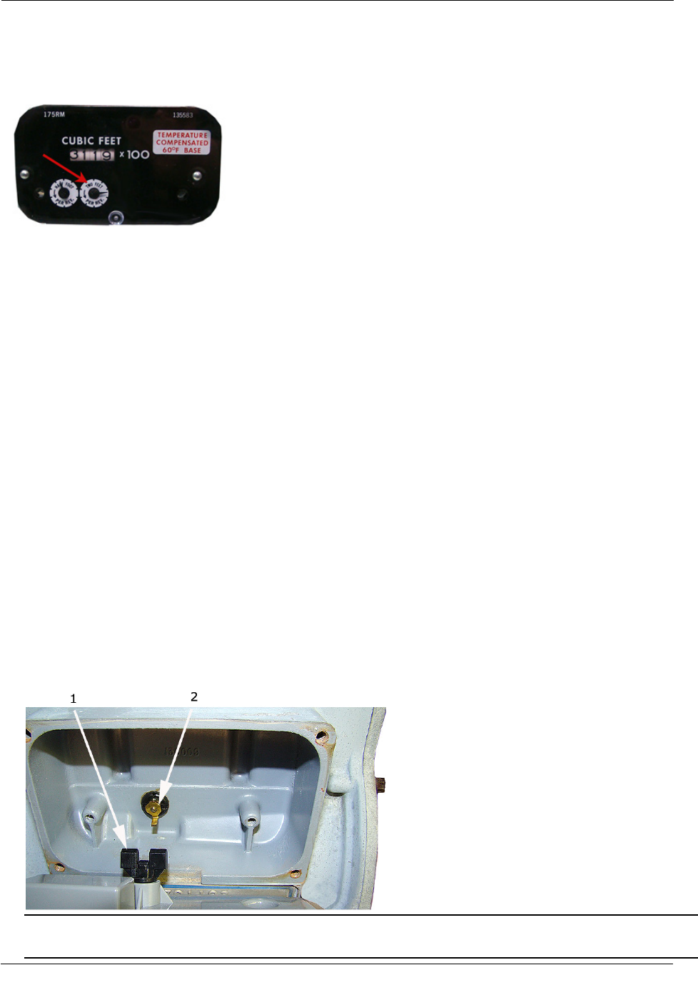
Itron Meter Installation
The ERT module is programmed based on the meter's drive rate. Take note of the index drive rate shown on
the drive dial on the index. The ERT module is programmed based on the drive rate. Sprague meter index
drive rates are typically 2-cubic feet.
To program the ERT module assembly
1. Program the meter drive rate into the 100G series gas ERT module using the endpoint programming
device.
2. For all programming and Check Endpoint operations, hold the handheld programmer as close to vertical as
possible. For optimal results, keep the handheld programmer within 6 feet of the target ERT module.
3. Verify you have the correct programming mode (Fixed Network Mode, Mobile High Power Mode,
Mobile/Handheld Mode, or Hard to Read Mobile/Handheld Mode) for your application.
4. Programming parameters are based on the configuration file loaded into the ERT module programming
device. During programming, the 100G is set to the nearest 100 cubic feet; the last two digits (tens and
units) are programmed as zeros (0). After programming is complete, the ERT module assembly will read
to the nearest cubic foot.
Installing the 100G Gas ERT Module Assembly on the Sprague 175RM
Meter
After you program the 100G, install the ERT assembly on the Sprague 175RM meter.
To install the ERT module on the 175RM meter
1. Align the module wriggler (1) with the meter's drive dog (2).
Warning Failure to properly align the ERT wriggler with the meter drive post can cause binding and lead
to poor registration or meter failure.
TDC-0823-014 100G Series Gas ERT Module Installation Guide, Direct Mount 46
Proprietary and Confidential
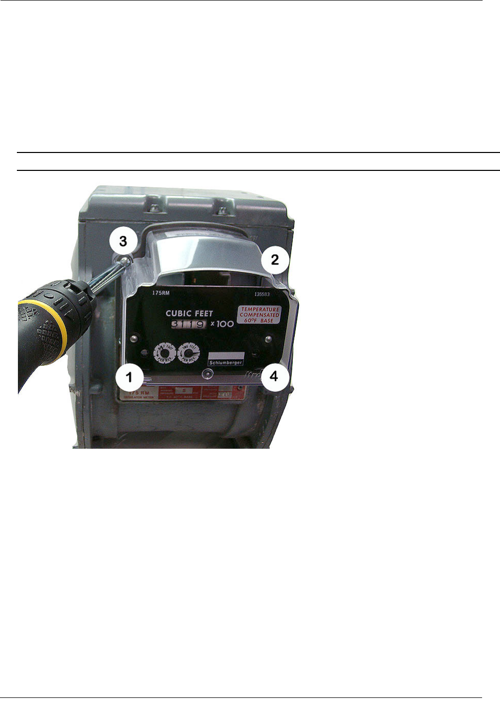
Itron Meter Installation
2. Use the replacement mounting screws shipped with the 100G. Install module-to-meter mounting screws in
an alternating pattern.
• Insert the right module mounting screw and tighten the screw enough to hold it in place. Do not
completely tighten the screw.
• Install the lower left module mounting screw and tighten two turns.
• Insert the lower right mounting screw and tighten two turns.
• Insert the upper left mounting screw and tighten to snug.
• Tighten the mounting screws in an alternating diagonal fashion as shown in the photo below.
Tighten each mounting screw evenly.
Important Meter manufacturers: torque the mounting screws 15 to 20 inch-pounds.
TDC-0823-014 100G Series Gas ERT Module Installation Guide, Direct Mount 47
Proprietary and Confidential
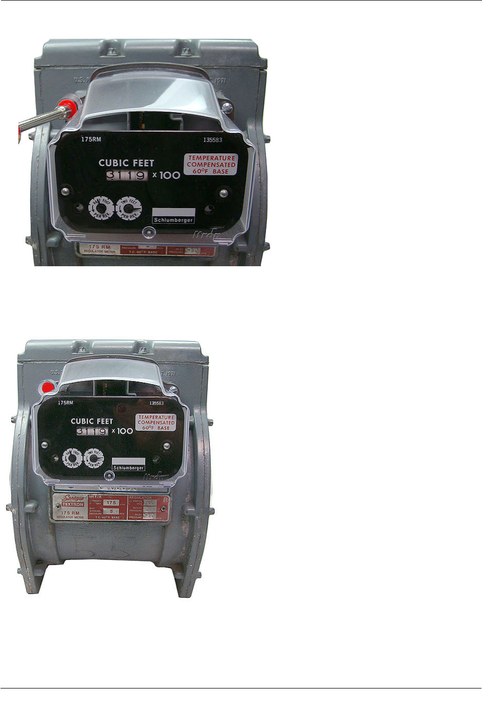
Itron Meter Installation
3. Place a new tamper seal over the two screws in the tamper seal cups. Press the new tamper seals into place
using an 11/32-inch nut driver or similar blunt tool.
4. Complete any necessary paperwork and properly dispose excess installation materials and scrap from the
customer premises.
100G installation on the Sprague 175RM meter is complete.
TDC-0823-014 100G Series Gas ERT Module Installation Guide, Direct Mount 48
Proprietary and Confidential