Itron 100GDLR AMR transceiver device for utility meters. User Manual 100G Datalogging Installation Guide Direct Mount
Itron, Inc. AMR transceiver device for utility meters. 100G Datalogging Installation Guide Direct Mount
Itron >
Contents
- 1. Users Manual Section 1
- 2. Users Manual Section 2
- 3. Users Manual Section 3
Users Manual Section 2
100G Datalogging Installation Guide - Direct Mount 21
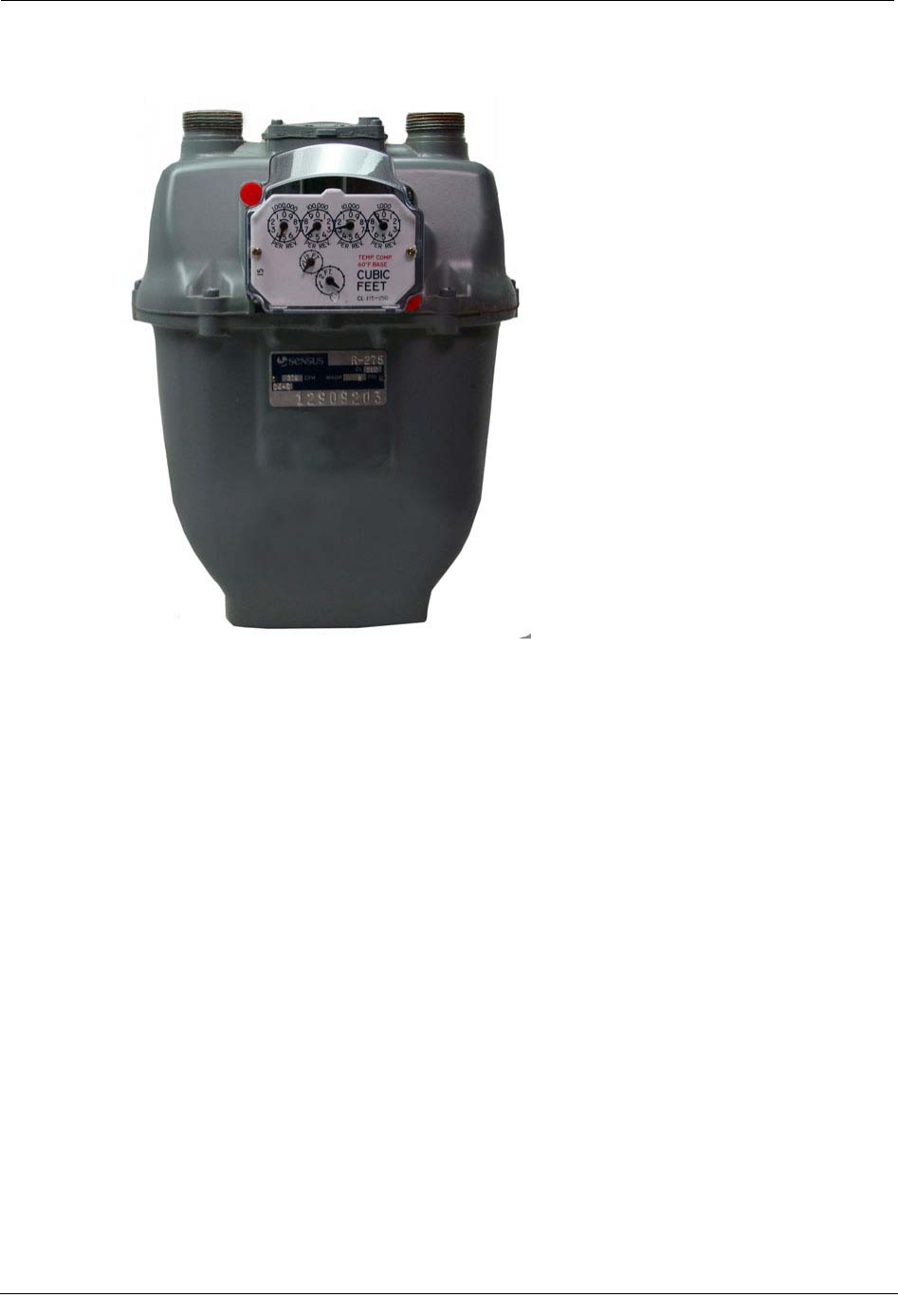
This chapter provides instructions to install the 100G Datalogging Gas Endpoint on a
Sensus/Rockwell Meter. These instructions apply to 11-tooth, 16-tooth, and 18-tooth Sensus
100G Datalogging Gas Endpoints.
Note Sensus meters are also known as Invensys, Equimeter, and Rockwell. For
these instructions, all meter types are referred to as Sensus meters.
100G Datalogging Gas Endpoint Sensus 11-tooth
Sensus 16-tooth
Sensus 18-tooth
C
HAPTER
3
Sensus/Rockwell Meter Installation
Chapter 3 Sensus/Rockwell Meter Installation
22 100G Datalogging Installation Guide - Direct Mount
To Remove the Index from the Meter
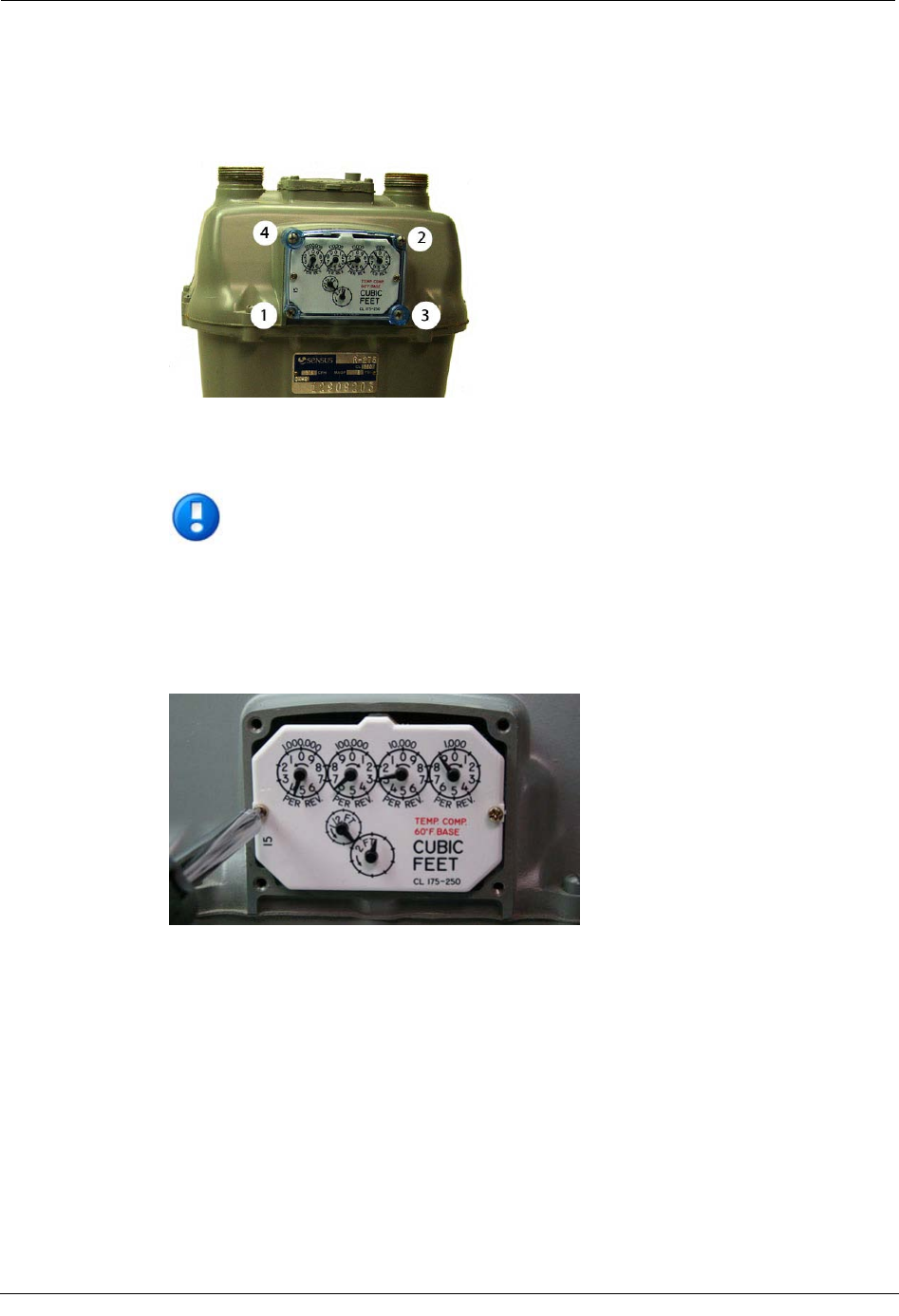
1. Remove the four index cover screws and the index cover from the Sensus meter.
Alternate screw removal following the numbered pattern as shown in the photo.
2. Examine the mounting screws. If they are 5/8" long and not corroded, keep them to
attach the 100G Datalogging Gas Endpoint assembly. If the screws are not the correct
length or if the screws are corroded, discard.
Note You may use the removed index cover as a temporary storage container for
screws. Properly dispose all unused screws, old index covers, gaskets, tamper
seals, and other leftover materials. Do not leave materials on customer premises.
3. Unscrew one index mounting screw completely. Hold one hand under the index to
catch the screw. While removing the other mounting screw, pull the index away from
the meter to keep the index backplate against the back of the screw. Remove the screw
completely after the index is free of the meter.
Set the index aside where it will not be damaged or fill with dirt, rain or snow. The
index will be mounted in the endpoint later in this procedure. Verify the index
mounting screws are 5/8" long and not corroded. If the screws are the correct length
and not corroded, retain for later use. If the original screws are discarded, use the
correct replacement screws (see Installation Prerequisites on page 8.)
Attaching the 100G Datalogging Gas Endpoint Assembly to the Elster American Meter
100G Datalogging Installation Guide - Direct Mount 23
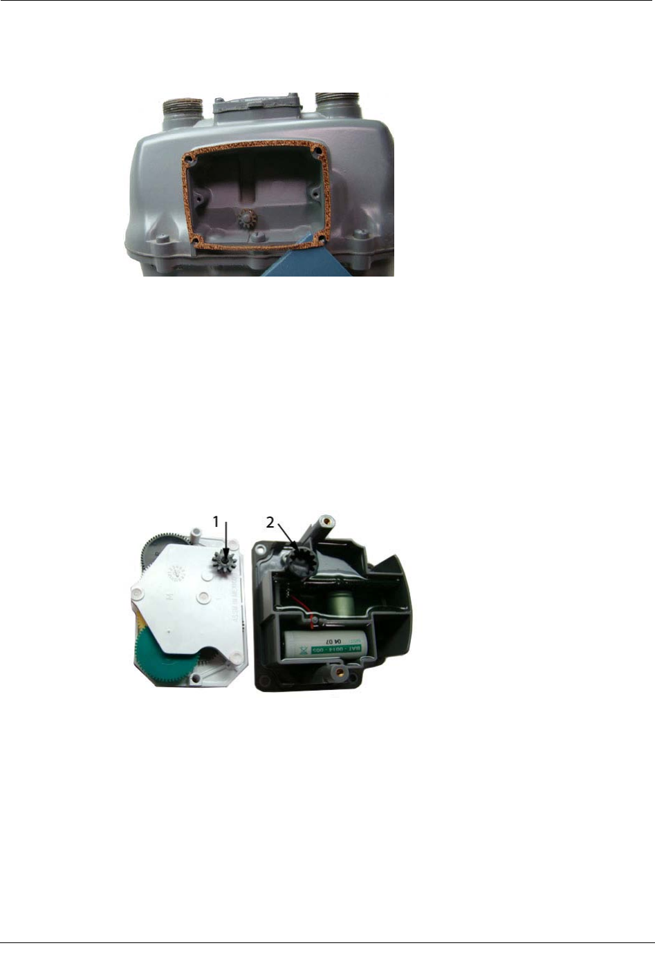
4. Remove the old gasket, gasket residue, and dirt from the meter (if applicable). The
meter face must be free of gasket residue or dirt before you install the 100G
Datalogging Gas Endpoint.
To Assemble the 100G Datalogging Gas Endpoint and Index
1. Separate the 100G Datalogging Gas Endpoint housing from the cover by pulling the
cover straight out from the housing. Set the endpoint cover aside where it will not be
damaged or fill with rain, dirt or snow. The cover will be used later in this installation
procedure.
2. Place the index drive gear (1) in the housing wriggler gear cup (2) of the endpoint.
The example shows an 11-tooth drive gear. Your index may be a 16- or 18-tooth gear.
Use the appropriate 100G Datalogging Gas Endpoint for your specific meter. See the
Meter Compatibility List on page 2 for more information.
Chapter 3 Sensus/Rockwell Meter Installation
24 100G Datalogging Installation Guide - Direct Mount
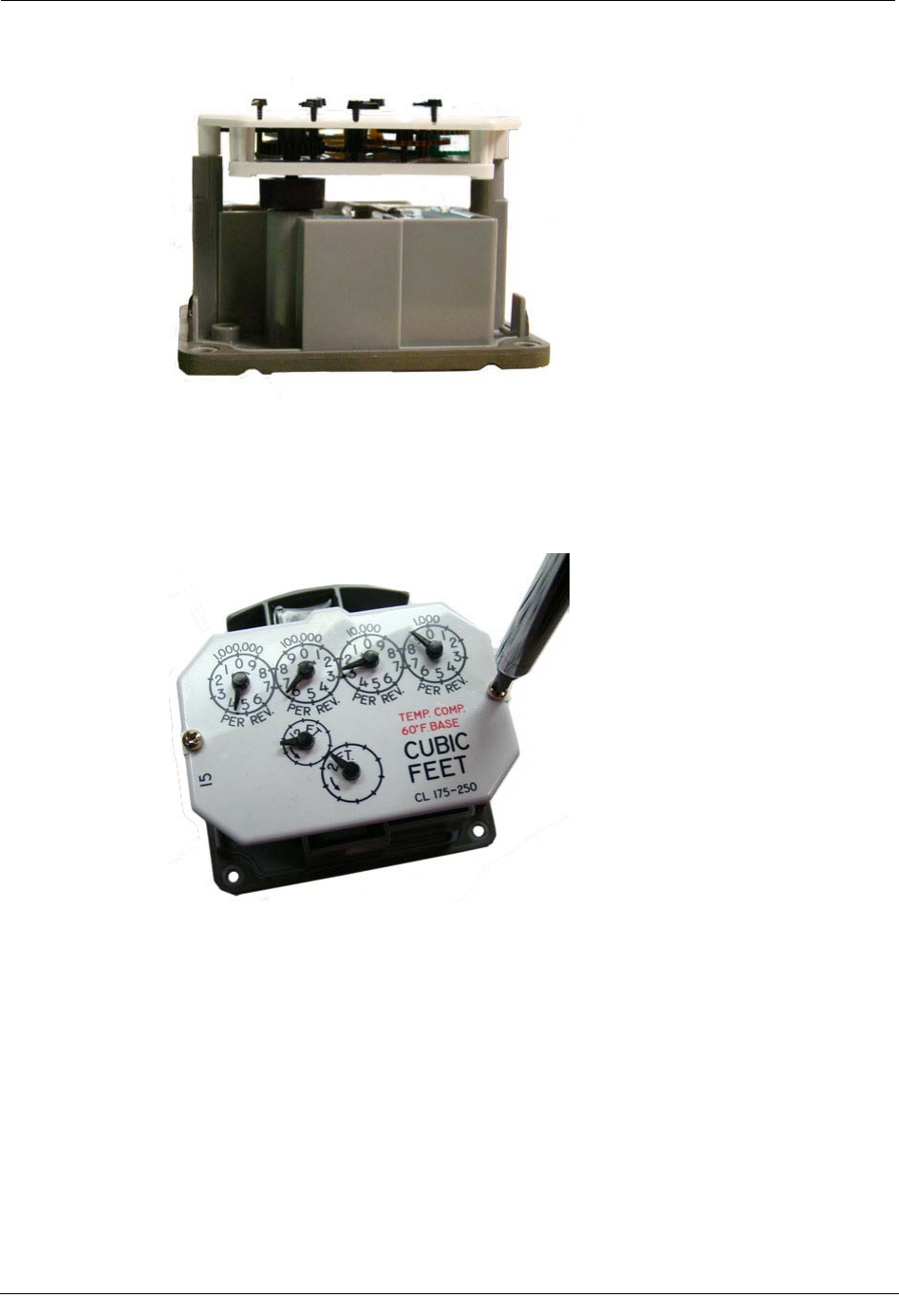
3. After the drive gear is aligned with the wriggler gear, the mounting holes will line up.
4. Using the original index mounting screw or a replacement screw (if necessary), place
one 6 - 32 5/8" screw into the index's right mounting screw hole. Attach the screw to
the endpoint housing's right-index mounting post just enough to hold the screw and
the right end of the index in place. Install and tighten the left index mounting screw.
Tighten the right index mounting screw completely.
Programming the 100G Datalogging Gas Endpoint Assembly
100G Datalogging Installation Guide - Direct Mount 25
5. Slide the endpoint cover over the index and housing. Verify the cover is installed
correctly. The endpoint label should be clearly visible and easily read.
Programming the 100G Datalogging Gas Endpoint Assembly
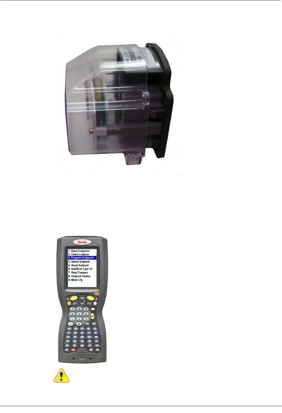
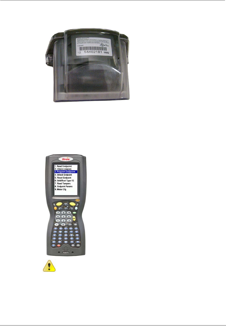
The 100G Datalogging Gas Endpoint must be programmed with the FC200SR
handheld computer loaded with EndPoint-Link® or Point-Link Pro® software version
5.3 or later. See the Endpoint-Link v5.3 (or later) Endpoint Programming Guide
(TDC-0744) for more complete programming information.
Caution The 100G Datalogging Gas Endpoint must be programmed before use.
Follow the steps in this section to properly program the endpoint.
Chapter 3 Sensus/Rockwell Meter Installation
26 100G Datalogging Installation Guide - Direct Mount
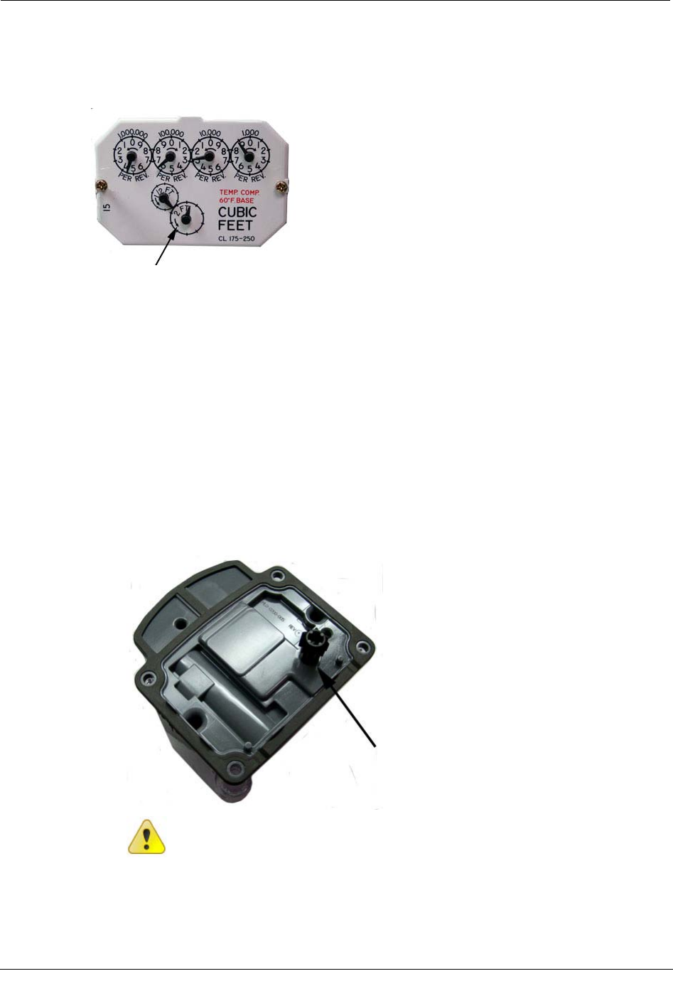
Take note of the index drive rate shown on a lower left dial on the index. The endpoint is
programmed based on the drive rate. Sensus meter index drive rates are typically 2-cubic
feet.
To Program the 100G Datalogging Gas Endpoint
1. Program the index drive rate into the 100G Datalogging Gas Endpoint using the
FC200SR. For all programming and "Check Endpoint" operations, hold the FC200SR
as close to vertical as possible. For best success, keep the FC200SR within 6 feet of
the target endpoint. Verify you have the correct programming mode (Fixed Network
Mode, Mobile/Handheld Mode, or Hard to Read Mobile/Handheld Mode) for your
application. Programming parameters are based on the mode defined by your system
administrator.
During programming, the 100G Datalogging Gas Endpoint is set to the nearest 100
cubic feet; the last two digits (tens and units) are programmed as zeros (0). After
programming is complete, the endpoint assembly will read to the nearest cubic foot.
2. Slowly turn the endpoint's drive wriggler two turns in the direction shown on the
index drive rate. This verifies the endpoint is counting properly after assembly.
Caution Do not turn the drive wriggler faster than one turn per second.
Attaching the 100G Datalogging Gas Endpoint Assembly to the Sensus Meter
100G Datalogging Installation Guide - Direct Mount 27
3. Read the 100G Datalogging Gas Endpoint using the FC200SR.
• If the read result is higher than the number programmed in Step 1, the 100G
Datalogging Gas Endpoint is counting correctly.
• If the read result is not higher than the number programmed in Step 1, replace
the 100G Datalogging Gas Endpoint.
Attaching the 100G Datalogging Gas Endpoint Assembly to
the Sensus Meter
After 100G Datalogging Gas Endpoint programming is complete, attach the endpoint
assembly to the Sensus meter.
To Attach the 100G Datalogging Gas Endpoint
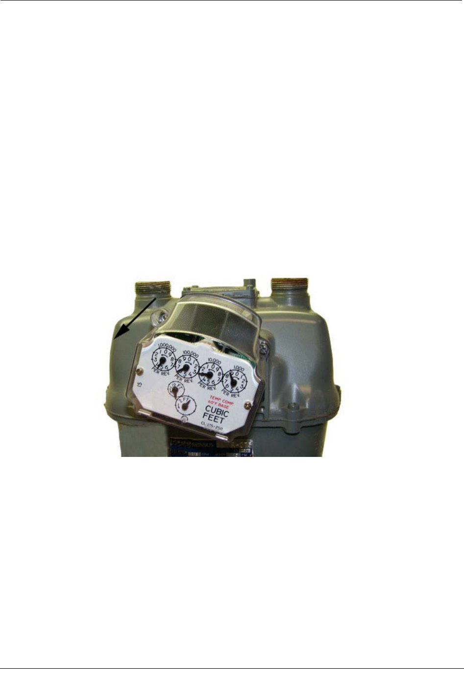
1. Gently place the ERT module assembly against the front of the meter at angle.
Endpoint-to-meter mounting screws are installed and tightened in an alternating
fashion. Align the top right mounting screw-hole on the meter with the top right
screw-hole on the endpoint. Insert the top-right cover mounting screw and tighten the
screw enough to hold it in place. Do not completely tighten. Rotate the Endpoint
assembly counterclockwise until the remaining three endpoint screw holes line up
with the holes in the meter. Use the original mounting screws if they were the correct
size and not corroded. If the original screws were discarded, use the correct
replacement screws (see Installation Prerequisites on page 8.)
Chapter 3 Sensus/Rockwell Meter Installation
28 100G Datalogging Installation Guide - Direct Mount
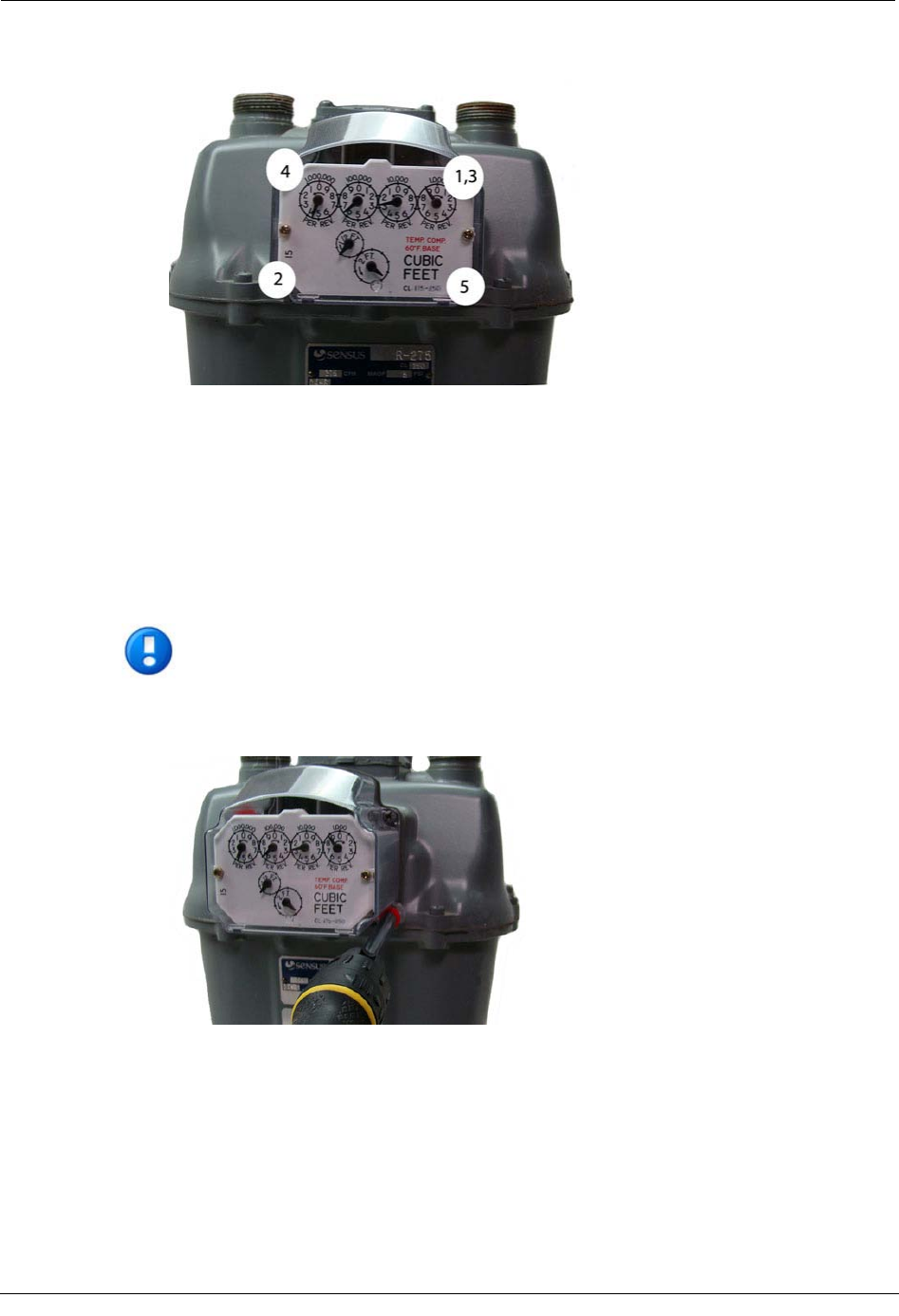
Install the remaining three mounting screws and tighten in the pattern shown.
• Insert lower left mounting screw and tighten to snug position.
• Tighten upper right mounting screw to snug position.
• Insert upper left mounting screw and tighten to snug position.
• Insert lower right mounting screw and tighten to snug position.
Each mounting screw should be tightened evenly.
Important Meter manufacturers should torque the mounting screws 15 to 20
inch-pounds.
2. Place a new tamper seal over the two screws with tamper seal cups. Press the new
tamper seals into place using the 11/32-inch nut driver (or similar blunt tool).
3. Complete any necessary paperwork and properly dispose excess installation materials
and scrap from the customer premises.
Attaching the 100G Datalogging Gas Endpoint Assembly to the Sensus Meter
100G Datalogging Installation Guide - Direct Mount 29
100G Datalogging Gas Endpoint installation on the Sensus Meter is complete.

Chapter 3 Sensus/Rockwell Meter Installation
30 100G Datalogging Installation Guide - Direct Mount
100G Datalogging Installation Guide - Direct Mount 31
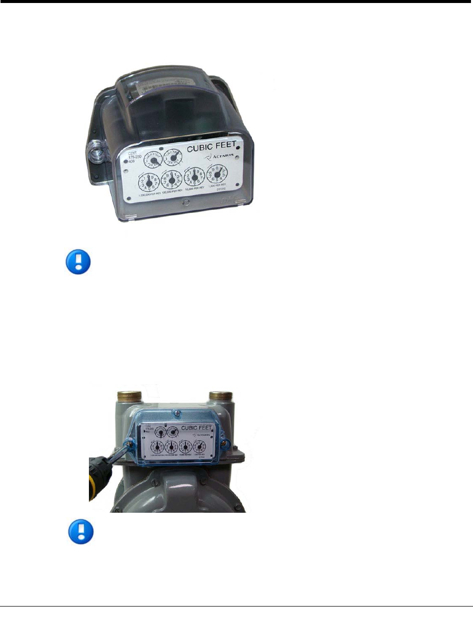
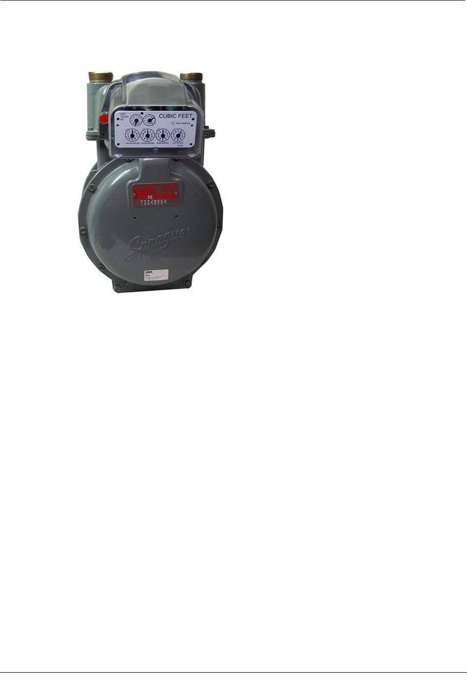
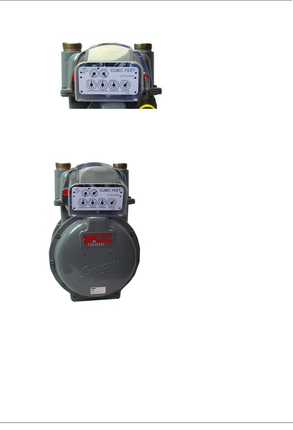
This chapter provides instructions to install the 100G Datalogging Gas Endpoint on an
Itron/Actaris Meter.
Note Itron/Actaris meters are also known as Sprague and Schlumberger meters.
For these instructions, all meters will be referred to as Itron/Actaris meters.
To remove the index from the meter
1. Remove the index cover screws and the index cover from the Itron/Actaris meter.
Examine the mounting screws. If they are 5/8" long and not corroded, keep them to re-
attach the 100G Datalogging Gas Endpoint assembly. If the screws are not the correct
length or if the screws are corroded, discard.
Note Use the removed index cover as a temporary storage container for
screws. Properly dispose all unused screws, old index covers, gaskets, tamper
seals, and other leftover materials. Do not leave materials on customer premises.
C
HAPTER
4
Itron/Actaris Meter Installation
Chapter 4 Itron/Actaris Meter Installation
32 100G Datalogging Installation Guide - Direct Mount
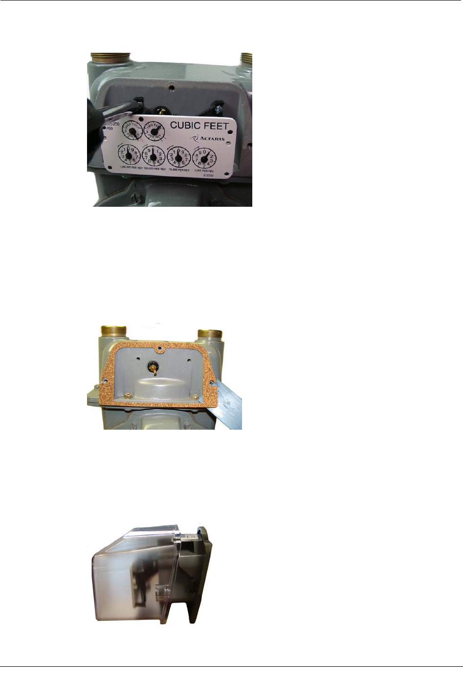
2. Loosen the index mounting screws 1/2 to one turn. Slide the index to the left and off
the mounting screws and remove from the meter.
Set the index aside where it will not be damaged or fill with dirt, rain or snow. The
index will be mounted in the endpoint later in this procedure. Verify the index
mounting screws are 1/4" long and not corroded. If the screws are the correct length
and not corroded, retain for later use. If the original screws are discarded, use the
correct replacement screws (see Installation Prerequisites on page 8.)
3. Remove the old gasket, gasket residue, and dirt from the meter (if applicable). The
meter face must be free of gasket residue or dirt before you install the 100G
Datalogging Gas Endpoint.
To assemble the 100G Datalogging Gas Endpoint and index
1. Separate the 100G Datalogging Gas Endpoint housing from the cover by pulling the
cover straight out from the housing. Set the endpoint cover aside where it will not be
damaged or fill with rain, dirt or snow. The cover will be used later in this installation
procedure.
Attaching the 100G Datalogging Gas Endpoint Assembly to the Sensus Meter
100G Datalogging Installation Guide - Direct Mount 33
2. Screw the 10 - 24 x 1/4" screws into the index mounting posts two turns. Do not
tighten the screws.
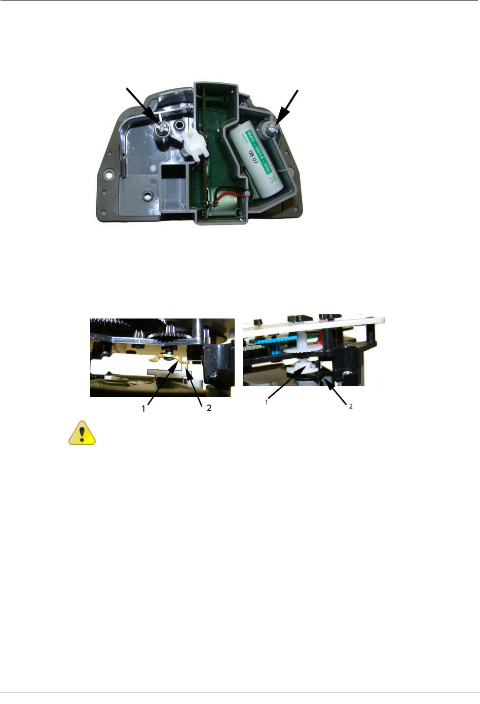
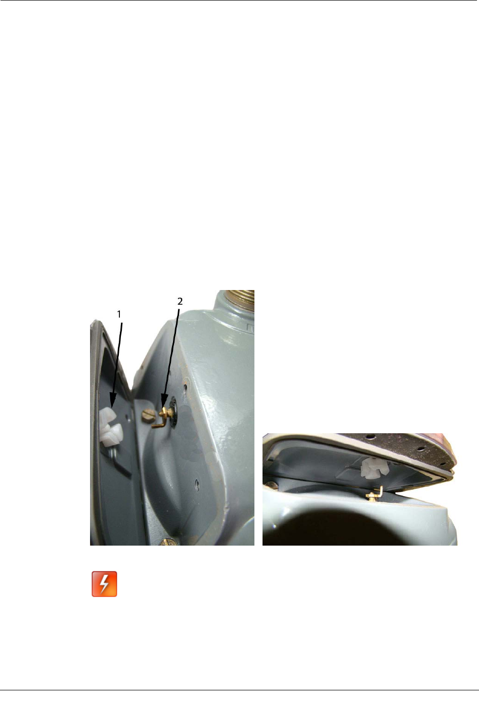
3. Align the index wriggler (1) with the endpoint drive post (2). Carefully slide the index
onto the mounting screws. Verify the 100G Datalogging Gas Endpoint's housing drive
post makes positive engagement with the index wriggler. Hold the index in place and
tighten the index mounting screws.
Caution Indexes have varying drive mechanism styles. The diagrams show a bar-
type (left) and "Scottish Yoke" type (right). Failure to align the endpoint wriggler
with the index drive post can cause binding and lead to poor registration or meter
failure. To verify proper engagement of the index to the endpoint housing, spin the
wriggler one clockwise rotation, then one-counterclockwise rotation. Do not spin
more than one complete rotation. The wriggler should spin freely, with little or no
resistance.
Chapter 4 Itron/Actaris Meter Installation
34 100G Datalogging Installation Guide - Direct Mount
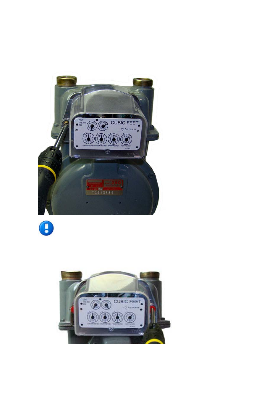
4. Slide the endpoint cover over the index and housing. Verify the cover is installed
correctly. The endpoint label should be clearly visible and easily read.
Programming the 100G Datalogging Gas Endpoint Assembly
The 100G Datalogging Gas Endpoint must be programmed with the FC200SR
handheld computer loaded with EndPoint-Link® or Point-Link Pro® software version
5.3 or later. See the Endpoint-Link v5.3 (or later) Endpoint Programming Guide
(TDC-0744) for more complete programming information.
Caution The 100G Datalogging Gas Endpoint must be programmed before use.
Follow the steps in this section to properly program the endpoint.
Programming the 100G Datalogging Gas Endpoint Assembly
100G Datalogging Installation Guide - Direct Mount 35
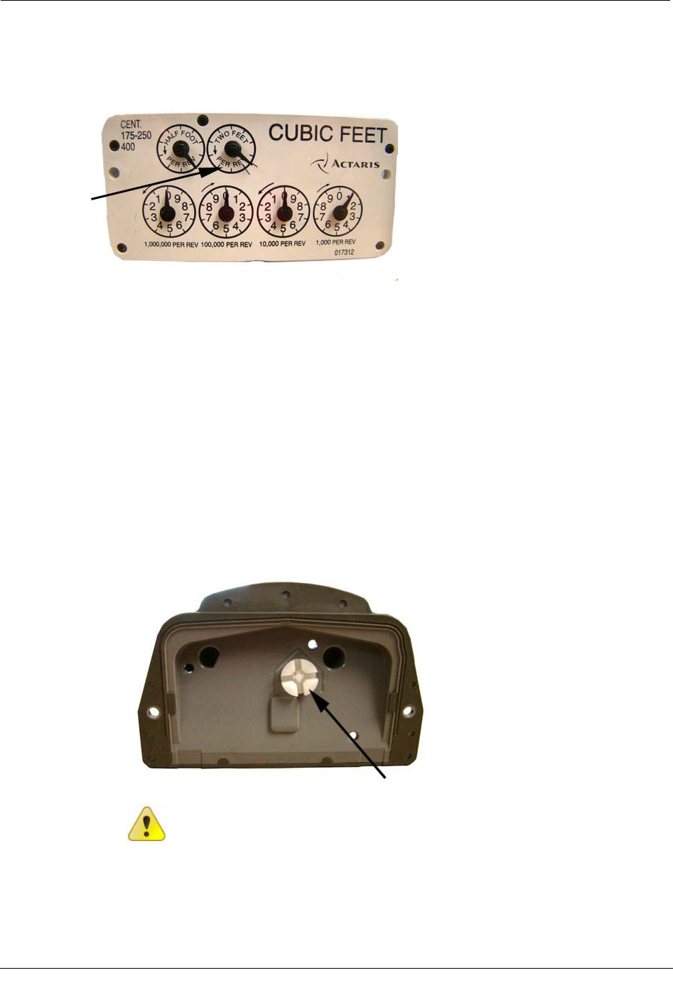
Take note of the index drive rate shown on the drive dial on the index. The endpoint is
programmed based on the drive rate. Itron/Actaris meter index drive rates are typically 2-
cubic feet.
To program the 100G Datalogging Gas Endpoint
1. Program the index drive rate into the 100G Datalogging Gas Endpoint using the
FC200SR. For all programming and "Check Endpoint" operations, hold the FC200SR
as close to vertical as possible. For best success, keep the FC200SR within 6 feet of
the target endpoint. Verify you have the correct programming mode (Fixed Network
Mode, Mobile/Handheld Mode, or Hard to Read Mobile/Handheld Mode) for your
application. Programming parameters are based on the mode defined by your system
administrator.
During programming, the 100G Datalogging Gas Endpoint is set to the nearest 100
cubic feet; the last two digits (tens and units) are programmed as zeros (0). After
programming is complete, the endpoint assembly will read to the nearest cubic foot.
2. Slowly turn the endpoint's drive wriggler two turns in the direction shown on the
index drive rate. This verifies the endpoint is counting properly after assembly.
Caution Do not turn the drive wriggler faster than one turn per second.
Chapter 4 Itron/Actaris Meter Installation
36 100G Datalogging Installation Guide - Direct Mount
3. Read the 100G Datalogging Gas Endpoint using the FC200SR.
• If the read result is higher than the number programmed in Step 1, the 100G
Datalogging Gas Endpoint is counting correctly.
• If the read result is not higher than the number programmed in Step 1, replace
the 100G Datalogging Gas Endpoint.
Attaching the 100G Datalogging Gas Endpoint Assembly to
the Itron/Actaris Meter
After the 100G Datalogging Gas Endpoint has been programmed, attach it to the
Itron/Actaris meter.
To attach the 100G Datalogging Gas Endpoint
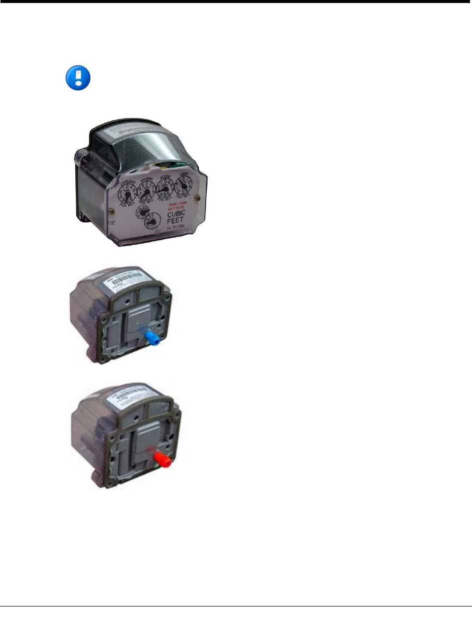
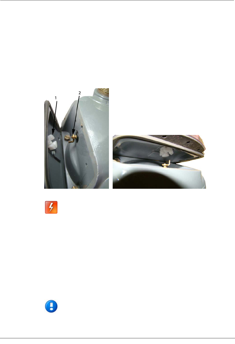
1. Align the white wriggler (1) so one of its four drive slots lines up with the meter's
drive dog (2).
2. Carefully place the 100G Datalogging Gas Endpoint on the meter.
Warning Failure to correctly align the meter drive post and endpoint drive slot
can cause binding and lead to poor registration or meter failure. If there is a gap
between the endpoint gasket and the meter, it may be the drive slot of the
endpoint assembly's wriggler is not correctly aligned with the meter drive slot.
Remove the 100G Datalogging Gas Endpoint assembly and repeat the
alignment procedure. You must establish proper engagement of the meter drive
dog within the endpoint wriggler slot.
Attaching the 100G Datalogging Gas Endpoi
nt Assembly to the Itron/Actaris Meter
100G Datalogging Installation Guide - Direct Mount 37
3. Endpoint to meter mounting screws must be installed in an alternating fashion. Use
the original mounting screws if they were the correct size and not corroded. If the
original screws were discarded, use the correct replacement screws (see Installation
Prerequisites on page 8.) Insert the right index cover mounting screw and tighten the
screw enough to hold it in place. Do not completely tighten. Install the left index
cover mounting screw and tighten to a snug fit. Finish by tightening the right
mounting screw to a snug fit. Each mounting screw must be tightened evenly.
Important Meter manufacturers should torque the mounting screws 15 to 20
inch-pounds.
1. Place a new tamper seal over the two screws in the tamper seal cups. Press the new
tamper seals into place using the 11/32-inch nut driver (or similar blunt tool).
2. Complete any necessary paperwork and properly dispose excess installation materials
and scrap from the customer premises.
Chapter 4 Itron/Actaris Meter Installation
38 100G Datalogging Installation Guide - Direct Mount
100G Datalogging Gas Endpoint installation on the Itron/Actaris Meter is complete.
Attaching the 100G Datalogging Gas Endpoint Assembly to the Itron/Actaris Meter
100G Datalogging Installation Guide - Direct Mount 39
Attaching the 100G Datalogging Gas Endpoint Assembly to
Flat-faced Itron/Actaris Meters
100G Datalogging Gas Endpoint installation on a flat-faced Itron/Actaris meter requires the
Itron Adapter Shim Kit (CFG-0015-001).
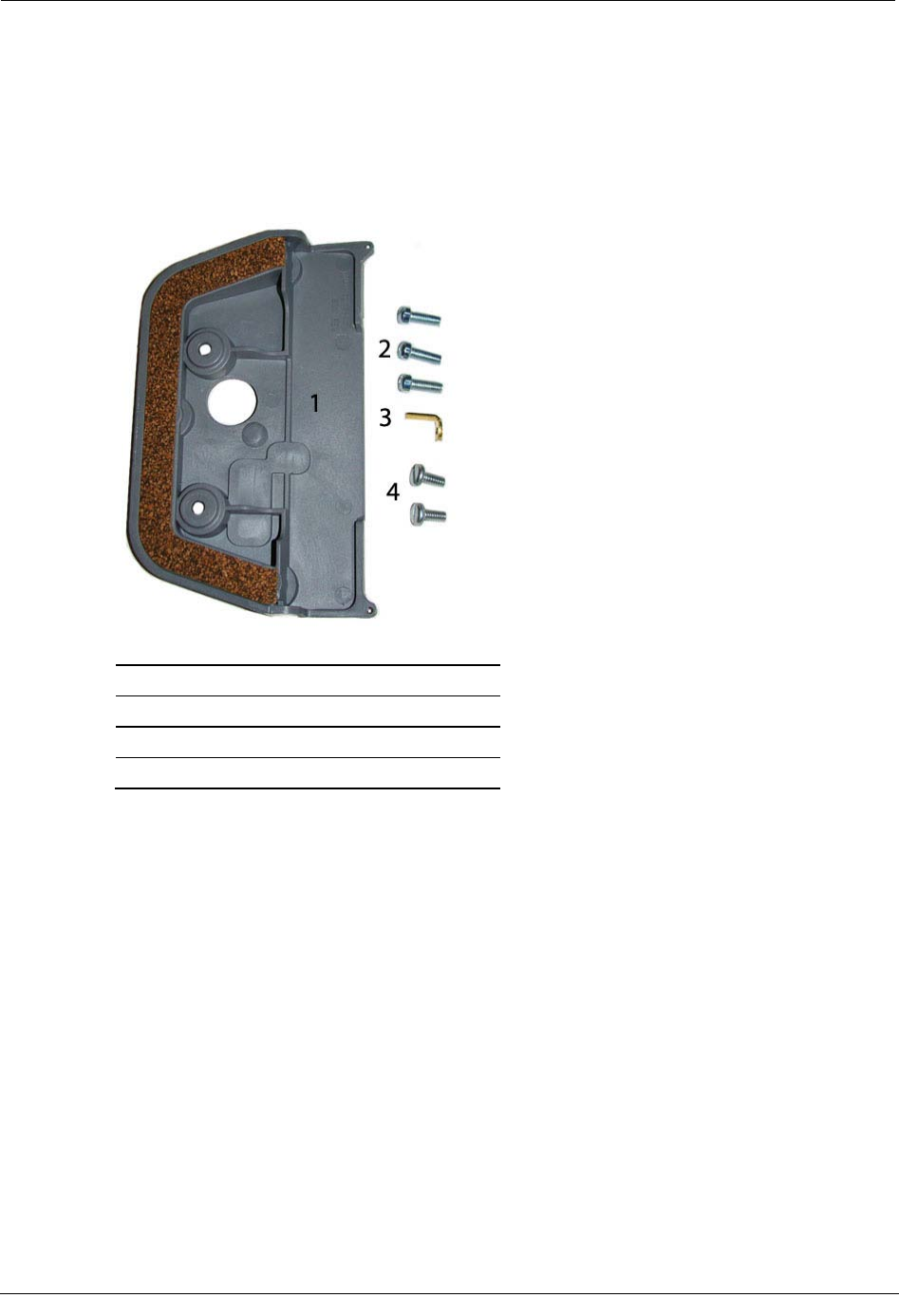
Itron Adapter Shim Kit (CFG-0015-001)
1 Adapter Shim Plate
2 Clear Cover Mounting Screws
3 Drive Dog
4 Adapter Plate Mounting Screws
To Attach the 100G Datalogging Gas Endpoint Assembly
1. Verify the kit includes the materials listed in the Itron Adapter Shim Kit Table.
Chapter 4 Itron/Actaris Meter Installation
40 100G Datalogging Installation Guide - Direct Mount
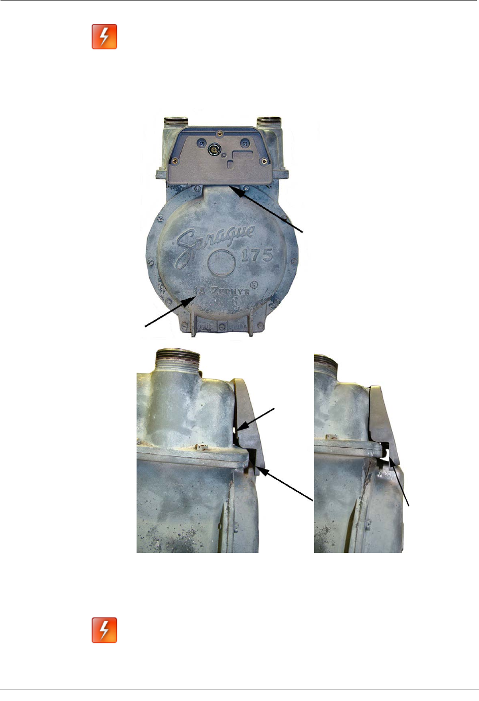
Warning The Adapter Shim Plate must fit flush against the meter face. Some
older Schlumberger/Sprague meters are not compatible with the adapter plate.
The following examples illustrate the potential obstruction (problem) areas
between the adapter plate and meter. Failure to mount adapter plate flush on
the front of a meter could result in a binding condition and lead to poor
registration or meter failure.
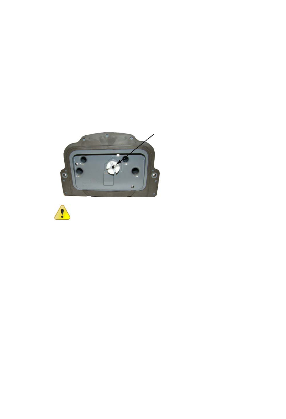
2. Remove the drive dog from the flat-faced Itron/Actaris meter. Replace it with the
extended drive dog included in the kit. Hand-tighten to snug.
Warning The meter drive dog shaft is surrounded by a gasket. A gas leak could
result if the gasket is damaged. Do not use a tool to install or tighten the new drive
dog. Hand-tighten only.
Attaching the 100G Datalogging Gas Endpoint Assembly to the Itron/Actaris Meter
100G Datalogging Installation Guide - Direct Mount 41
3. Attach the Adapter Shim Plate to the meter with the gasket against the meter face.
Secure with the two adapter plate mounting screws in an alternating fashion.
• Insert the right adapter plate screw and tighten the screw enough to hold it in
place.
• Install the left mounting screw and tighten to a snug fit.
• Finish by tightening the right mounting screw to a snug fit.
Each adapter plate screw must be tightened evenly.
Note 100G Datalogging Gas Endpoints must be assembled and programmed
following the instructions in To Assembe the 100G Datalogging Ga
s Endpoint and
Index on page 32 and Programming the 100G Datalogging Gas Endpoint
Assembly on page 34 prior to installation on the meter.
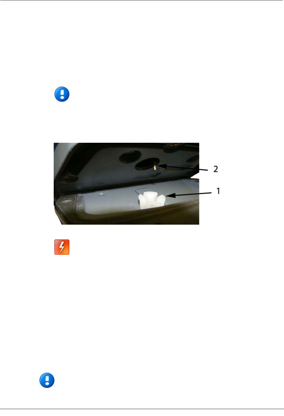
4. Align the white wriggler (1) so one of its four drive slots lines up with the meter's
drive dog (2).
5. Carefully place the 100G Datalogging Gas Endpoint assembly on the meter.
Warning Failure to correctly align the meter drive post and endpoint drive slot
can cause binding and lead to poor registration or meter failure. If there is a gap
between the endpoint gasket and the meter, remove the 100G Datalogging Gas
Endpoint assembly and repeat the alignment procedure. You must engage the
meter drive dog in the endpoint wriggler slot.
6. Secure the endpoint to the meter by installing mounting screws in an alternating
fashion. Use the original index cover mounting screws if they were the correct size
and not corroded. If the original screws were discarded, use the correct replacement
screws (see Installation Prerequisites on page 8.)
• Insert the right index cover mounting screw and tighten the screw enough to
hold it in place. Do not completely tighten.
• Install the left index cover mounting screw and tighten to a snug fit.
• Finish by tightening the right mounting screw to a snug fit.
Each mounting screw must be tightened evenly.
Important Meter manufacturers should torque the mounting screws 15 to 20
inch-pounds.
Chapter 4 Itron/Actaris Meter Installation
42 100G Datalogging Installation Guide - Direct Mount
1. Place a new tamper seal over the two screws with tamper seal cups. Press the new
tamper seals into place using the 11/32-inch nut driver or similar blunt tool.
2. Complete any necessary paperwork and properly dispose excess installation materials
and scrap from the customer premises.
100G Datalogging Gas Endpoint installation on the Itron/Actaris Meter is complete.
Attaching the 100G Datalogging Gas Endpoint Assembly to the Itron/Actaris Meter
100G Datalogging Installation Guide - Direct Mount 43
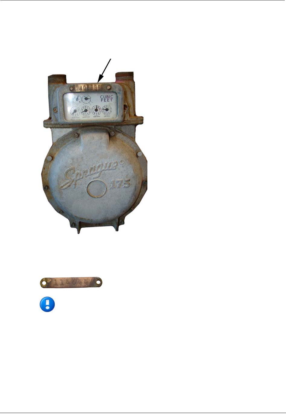
Securing Brass Meter Tags to Flat-faced Meters
Some older Sprague meters have metal index covers with brass meter tags attached (by
screws or rivets) to metal index covers.
Typically, brass meter tags have mounting (screw/rivet) holes on each end of the tag.
Note If the brass meter tag will be secured to the meter utilizing the endpoint-to-
meter mounting hole, it must be attached during the endpoint installation
procedure described in Step 1 of
Attaching the 100G Datalogging Gas Endpoint to
the Itron/Actaris Meter on page 36.
Chapter 4 Itron/Actaris Meter Installation
44 100G Datalogging Installation Guide - Direct Mount
To Secure Brass Meter Tags to Flat-faced Meters
1. After the metal index cover is removed from the meter, carefully remove the brass
meter tag from the meter index cover. Do not damage the meter tag mounting holes.
The Itron Adapter Shim Plate was designed with a tag mounting hole in the lower
right corner. After the 100G Datalogging Gas Endpoint assembly is attached to the
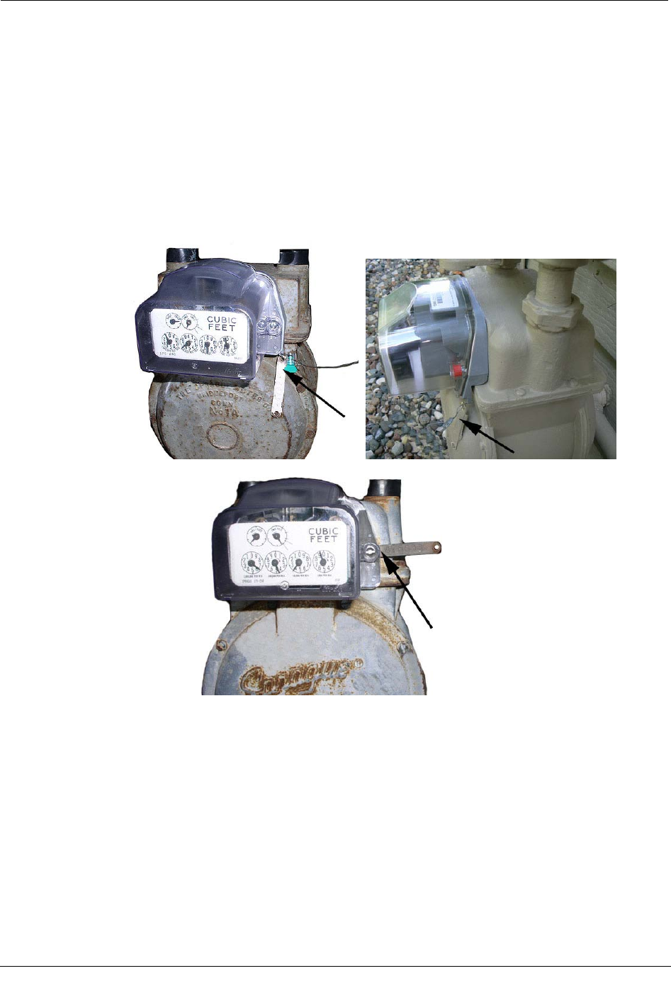
meter, secure the meter tag to the Shim Plate meter tag mounting hole with a utility-
approved wire security seal. Itron acceptable meter tag mounting methods are shown
in the photos.
Attaching the 100G Datalogging Gas Endpoint Assembly to the Itron/Actaris Meter
100G Datalogging Installation Guide - Direct Mount 45
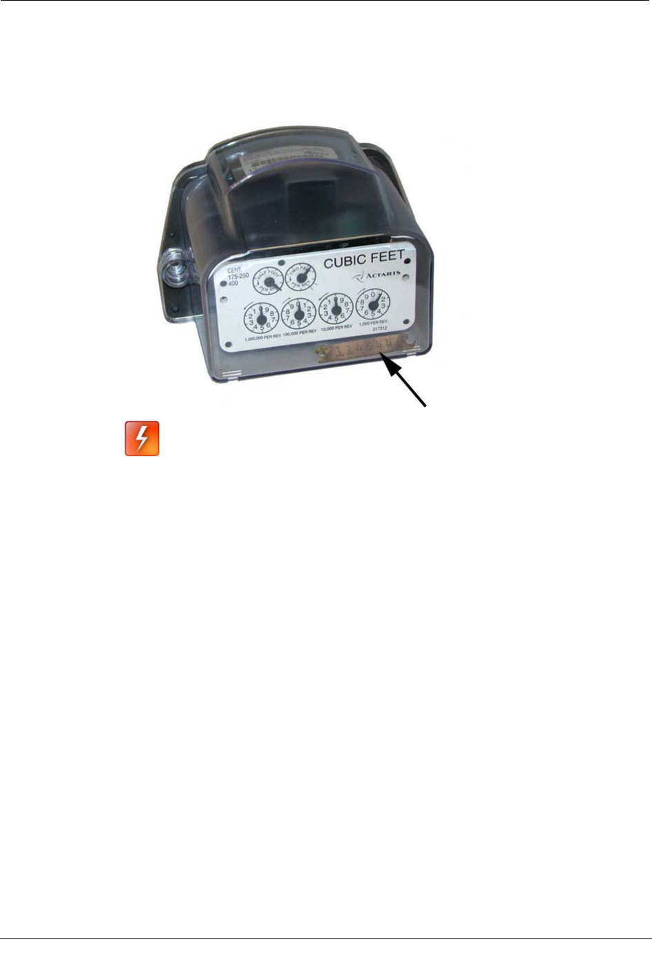
2. If the meter tag mounting holes were damaged during removal so a wire security seal
cannot be used, remove the 100G Datalogging Gas Endpoint index cover and place
the meter tag inside the endpoint assembly to maintain meter security. (See To
Assemble the 100G Datalogging Gas Endpoint on page 32.)
Warning Placing the brass meter tag inside the 100G Datalogging Gas
Endpoint assembly is not the preferred method of securing the tag to the meter.
Use this method only if the brass meter tag mounting holes are damaged and
cannot be used for mounting. This method does not secure the tag inside the
endpoint. The brass meter tag may move out of view if the meter is bumped or
jarred.

Chapter 4 Itron/Actaris Meter Installation
46 100G Datalogging Installation Guide - Direct Mount
100G Datalogging Installation Guide - Direct Mount 47
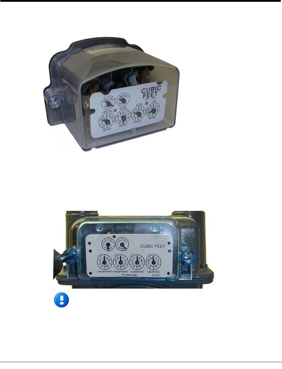
This chapter provides instructions to install the 100G Datalogging Gas Endpoint on 175 -
250 CFH National/Lancaster meters.
To Remove the Index from the Meter
1. Remove any tamper seals from the index cover screws. Remove the index cover
screws and the index cover from the meter. Discard the index cover mounting screws
and index cover. The 100G Datalogging Gas Endpoint includes new, different-size
endpoint mounting screws
Note You may use the removed index cover as a temporary storage container for
screws. Properly dispose all unused screws, old index covers, gaskets, tamper
seals, and other leftover materials. Do not leave materials on customer premises.
C
HAPTER
5
National/Lancaster Meter Installation
Chapter 5 National/Lancaster Meter Installation
48 100G Datalogging Installation Guide - Direct Mount
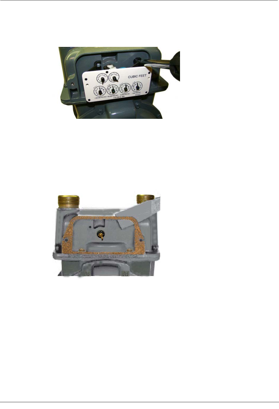
2. Unscrew one index mounting screw completely. Hold one hand under the index to
catch the screw. While removing the other mounting screw, pull the index away from
the meter to keep the index backplate against the back of the screw. Remove the screw
completely after the index is free of the meter.
Set the index aside where it will not be damaged or fill with dirt, rain or snow. The
index will be mounted in the endpoint later in this procedure. Discard the index
mounting screws. The 100G Datalogging Gas Endpoint for National/Lancaster meters
includes new, different-sized index mounting screws (see Installation Prerequisites on
page 8 for screw information).
3. Remove the old gasket, gasket residue, and dirt from the meter (if applicable). The
meter face must be free of gasket residue or dirt before you install the 100G
Datalogging Gas Endpoint assembly.
Attaching the 100
G Datalogging Gas Endpoint Assembly to the Itron/Actaris Meter
100G Datalogging Installation Guide - Direct Mount 49
To Assemble the 100G Datalogging Gas Endpoint and Index
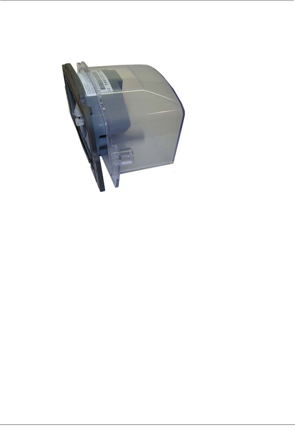
1. Separate the 100G Datalogging Gas Endpoint housing from the cover by pulling the
cover straight out from the housing.
2. Set the endpoint cover aside where it will not be damaged or fill with rain, dirt or
snow. The cover will be used later in this installation procedure.
Chapter 5 National/Lancaster Meter Installation
50 100G Datalogging Installation Guide - Direct Mount
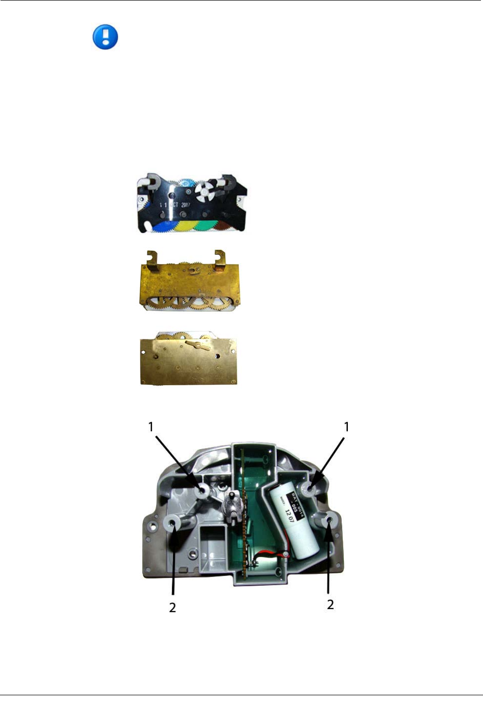
Note National/Lancaster meter indexes are available in different models:
Some National/Lancaster Meter indexes have index legs
to mount the index on the
meter or endpoint. Some indexes have both legs and index mounting holes and
some have just mounting holes. Mounting methods are dependent on the index.
Index types require different mounting screws to attach the index to the 100G
Datalogging Gas Endpoint housing (see Installation Prerequisites on page 8).
Indexes with legs must be mounted to the endpoint housing mounting posts.
Indexes with mounting holes must be attached to the endpoint housing's bracket
mounting posts.
1 Bracket mounting posts (indexes with legs)
2 Housing mounting posts (indexes without legs)
Attaching the 100G Datalogging Gas Endpoint Assembly to the Itron/Actaris Meter
100G Datalogging Installation Guide - Direct Mount 51
If your index has legs with mounting screw slots, skip steps 3 and 4. If your index has
mounting screw holes in the index back plate (no legs), perform steps 3 and 4, and
skip steps 5 and 6.
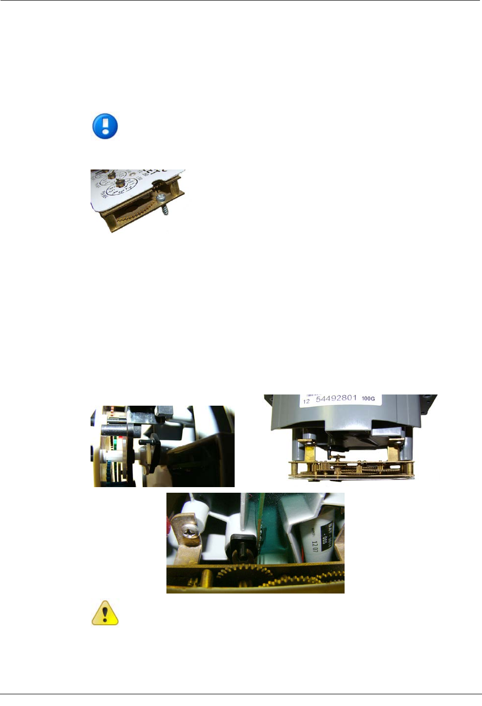
3. For indexes with mounting screw holes in the index back plate (no legs), use
replacement index mounting screws (SCR-0037-001 - see Installation Prerequisites on
page 8). Place one screw into the index's right-hand mounting screw hole.
Note National/Lancaster index mounting screws are thread-forming screws and
may require more torque.
4. Attach the screw to the endpoint housing's right-index mounting post just enough to
hold the screw and the right end of the index in place.
5. For indexes with legs (mounting slots), screw one 6 - 19 x 3/16" screw (SCR-0015-
001 - see Installation Prerequisites on page 8 for screw information) into the right
index mounting post one or two turns. Do not completely tighten the screw.
6. Place the right index mounting screw slot under the screw head. Do not completely
tighten the screw.
7. Carefully slide the index drive post into the endpoint wriggler. Verify positive
engagement of the index wriggler to the endpoint drive dog. (The following photos
show three types of index/wrigglers with positive engagement.)
Caution Verify the index drive slot engages with the 100G Datalogging Gas
Endpoint wriggler. Failure to mate the endpoint wriggler with the index drive post
(or slot) can cause binding and lead to poor registration or meter failure.
Chapter 5 National/Lancaster Meter Installation
52 100G Datalogging Installation Guide - Direct Mount
8. Install and tighten the left index mounting screw (for indexes with either mounting
screw slots or holes). Tighten the right index mounting screw. Each index mounting
screw must be tightened evenly.
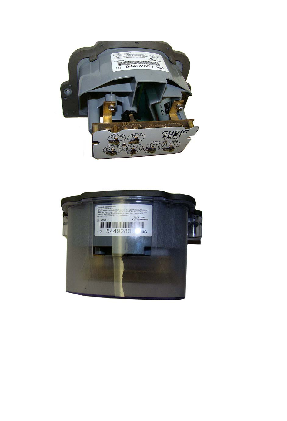
9. Slide the endpoint cover over the index and housing. Verify the cover is installed
correctly. The endpoint label should be clearly visible and easily read.
Programming the 100G Datalogging Gas Endpoint Assembly
100G Datalogging Installation Guide - Direct Mount 53
Programming the 100G Datalogging Gas Endpoint Assembly
The 100G Datalogging Gas Endpoint must be programmed with the FC200SR
handheld computer loaded with EndPoint-Link® or Point-Link Pro® software version
5.3 or later. See the Endpoint-Link v5.3 (or later) Endpoint Programming Guide
(TDC-0744) for more complete programming information.
Caution The 100G Datalogging Gas Endpoint must be programmed before use.
Follow the steps in this section to properly program the endpoint.
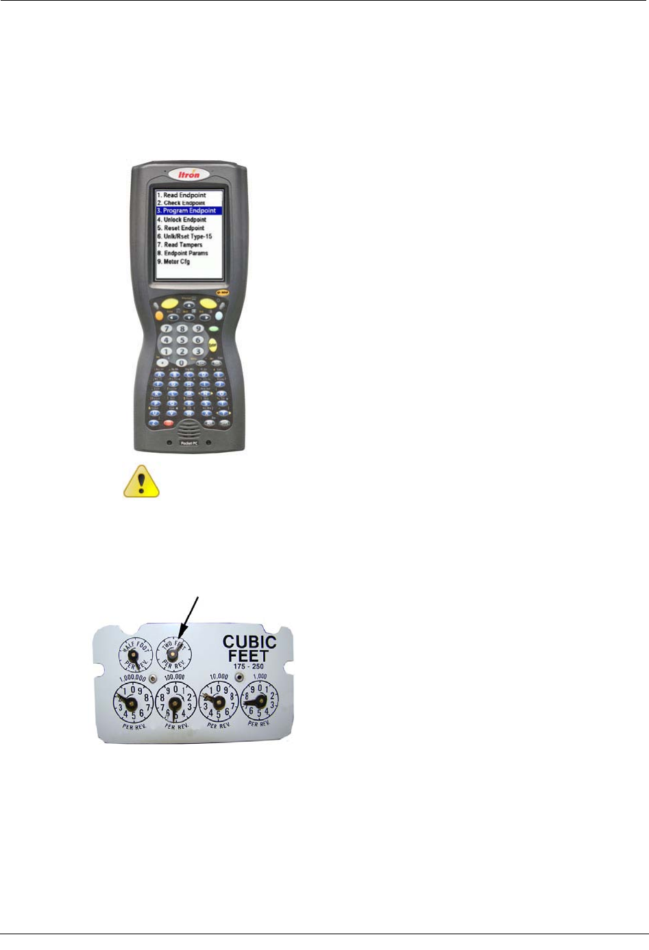
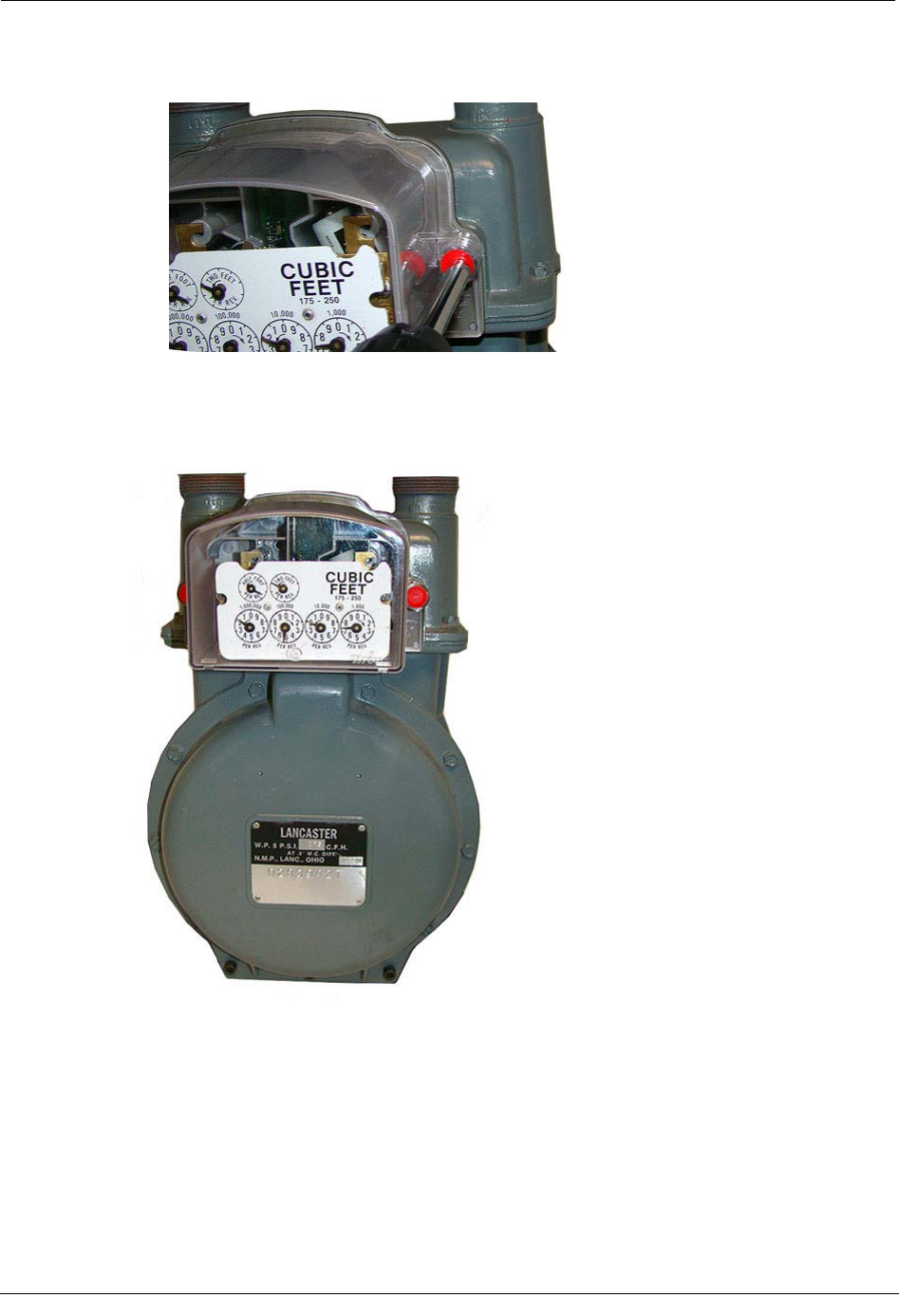
Take note of the index drive rate shown on a top right dial on the index. The endpoint is
programmed based on the drive rate. National/Lancaster meter index drive rates are
typically 2-cubic feet.
Chapter 5 National/Lancaster Meter Installation
54 100G Datalogging Installation Guide - Direct Mount
To Program the 100G Datalogging Gas Endpoint
1. Program the index drive rate into the 100G Datalogging Gas Endpoint using the
FC200SR. For all programming and "Check Endpoint" operations, hold the FC200SR
as close to vertical as possible. For best success, keep the FC200SR within 6 feet of
the target endpoint. Verify you have the correct programming mode (Fixed Network
Mode, Mobile/Handheld Mode, or Hard to Read Mobile/Handheld Mode) for your
application. Programming parameters are based on the mode defined by your system
administrator.
During programming, the 100G Datalogging Gas Endpoint is set to the nearest 100
cubic feet; the last two digits (tens and units) are programmed as zeros (0). After
programming is complete, the endpoint assembly will read to the nearest cubic foot.
2. Slowly turn the endpoint's drive wriggler two turns in the direction shown on the
index drive rate. This verifies the endpoint is counting properly after assembly.
Caution Do not turn the drive wriggler faster than one turn per second.
3. Read the 100G Datalogging Gas Endpoint using the FC200SR.
• If the read result is higher than the number programmed in Step 1, the 100G
Datalogging Gas Endpoint is counting correctly.
• If the read result is not higher than the number programmed in Step 1, replace
the 100G Datalogging Gas Endpoint.
Attaching the 100G Datalogging Gas Endpoint Assembly to the National/Lancaster Meter
100G Datalogging Installation Guide - Direct Mount 55
Attaching the 100G Datalogging Gas Endpoint Assembly to
the National/Lancaster Meter
After the 100G Datalogging Gas Endpoint has been programmed, attach it to the
National/Lancaster meter.
To Attach the 100G Datalogging Gas Endpoint
1. Align the white wriggler (1) so one of its four drive slots lines up with the meter's
drive dog (2).
2. Carefully place the 100G Datalogging Gas Endpoint on the meter.
Warning Failure to correctly align the meter drive post and endpoint drive slot
can cause binding and lead to poor registration or meter failure. If there is a gap
between the endpoint gasket and the meter, it may be the drive slot of the
endpoint assembly's wriggler is not correctly aligned with the meter drive slot.
Remove the 100G Datalogging Gas Endpoint assembly and repeat the
alignment procedure. You must engage endpoint wriggler in the meter drive
dog.
3. Install endpoint to meter mounting screws in an alternating fashion. 100G
Datalogging Gas Endpoints for National/Lancaster meters come with new, different-
size endpoint mounting screws (SCR-0014-004 - see Installation Prerequisites on page
8 for screw information.) Insert the right index cover mounting screw and tighten the
screw enough to hold it in place. Do not completely tighten. Install the left index
cover mounting screw and tighten to a snug fit. Finish by tightening the right
mounting screw to a snug fit. Each endpoint mounting screw must be tightened
evenly.
Important Meter manufacturers should torque the mounting screws 15 to 20
inch-pounds.
Chapter 5 National/Lancaster Meter Installation
56 100G Datalogging Installation Guide - Direct Mount
4. Place new tamper seals over the screws. Press the new tamper seals into place using
the 11/32-inch nut driver or similar blunt tool.
5. Complete any necessary paperwork and properly dispose excess installation materials
and scrap from the customer premises.
100G Datalogging Gas Endpoint installation on the National/Lancaster Meter is complete.