Itron 100GDLRS AMR transceiver device for utility meters User Manual 2
Itron Inc AMR transceiver device for utility meters Users Manual 2
Itron >
Contents
Users Manual 2
Mounting the 100G Series Remote Gas Module
TDC
-0824-006 100G Series Gas ERT Module Installation Guide, Remote Mount 15
Proprietary and Confidential
Mounting the Remote Gas Module on a Wall or Other Flat
Vertical Surface
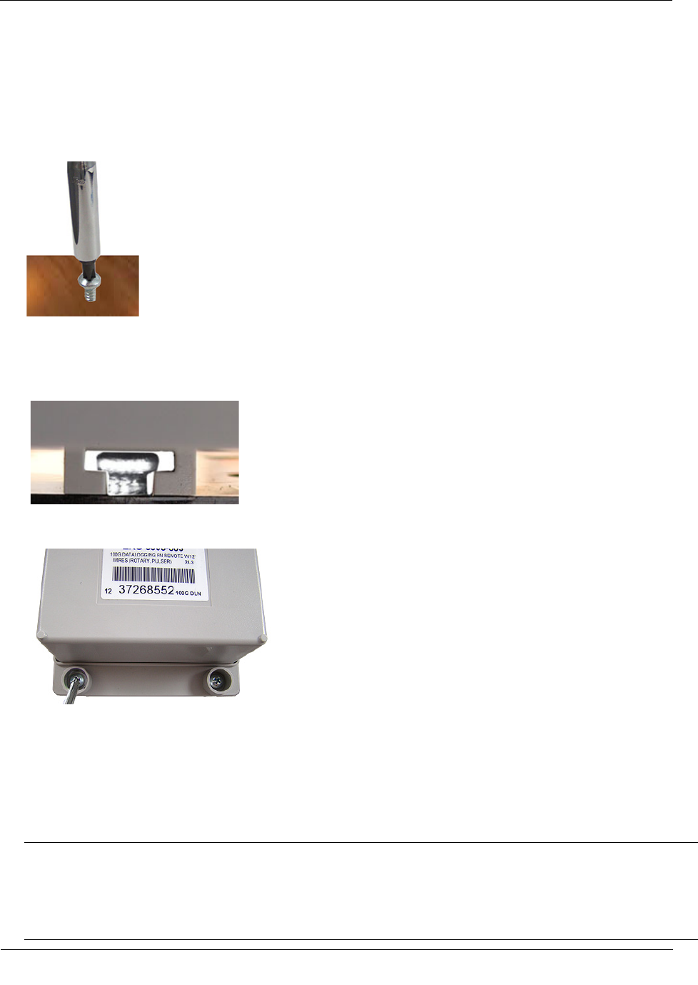
1. Using one of the three 1-1/2-inch mounting screws from the Remote Mount Installation Kit, turn the
mounting screw for the mounting lug (top of module) part way into the mounting surface.
2. Place the 100G series remote gas module mounting lug recess (on the top of the module backplate) just
under the screw head.
3. Slide the module upward until the screw head fits completely inside the mounting lug recess. Several
adjustments may be necessary to properly position the screw for module mounting.
4. Install the bottom two mounting screws. Fasten the screws in an alternating pattern until fully tightened to
secure the module firmly in position.
Note For easier installation, drill three pilot holes in the mounting surface (use the correct size drill bit to
accommodate the module mounting screws [see the drilling template below]). The drilled pilot holes for
the two bottom screws must be on a horizontal line. To mount the module on a sheet metal surface, use
the mounting screws included with the Remote Mounting kit. Use a comparable wood screw to mount the
module on a vertical wood surface.
Mounting the 100G Series Remote Gas Module
TDC
-0824-006 100G Series Gas ERT Module Installation Guide, Remote Mount 16
Proprietary and Confidential
Carefully select a mounting location free from electrical wires. The mounting location must have the
proper clearance to accommodate the 1-1/2-inch module mounting screws so nothing is damaged by the
drill or mounting screws.
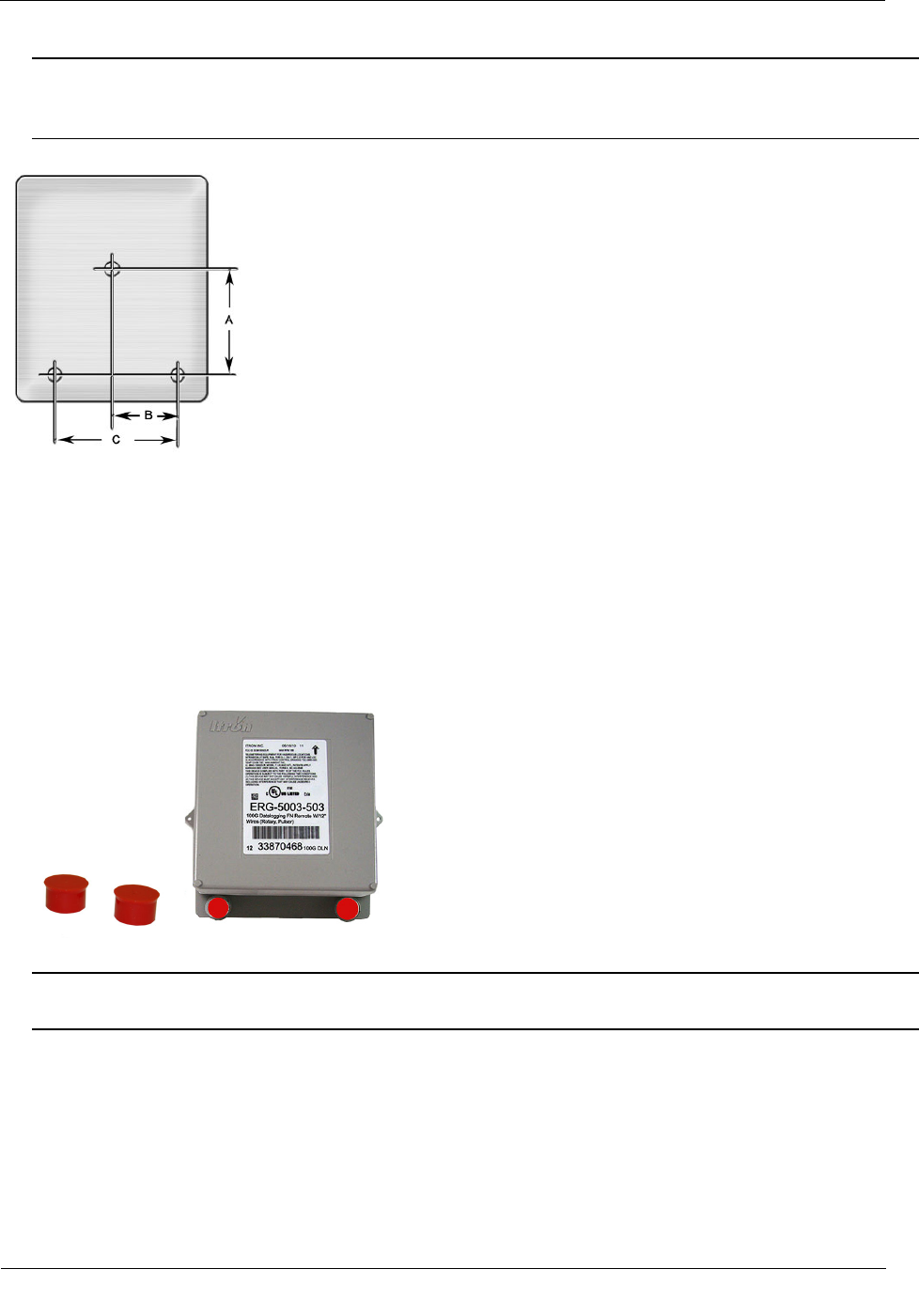
Remote module drilling template
A 3 inches
B 1-11/16 inches
C 3-3/8 inches
To install tamper seals and cable ties
1. Place a new tamper seal (from the Remote Mount Installation Kit) over each ERT module mounting
screw.
2. Firmly push both tamper seals into place with a 1/4-inch nut driver or similar blunt tool.
Note A tamper seal is fully seated when the top of the tamper seal is approximately 1/16-inch below the
top of the screw recess.
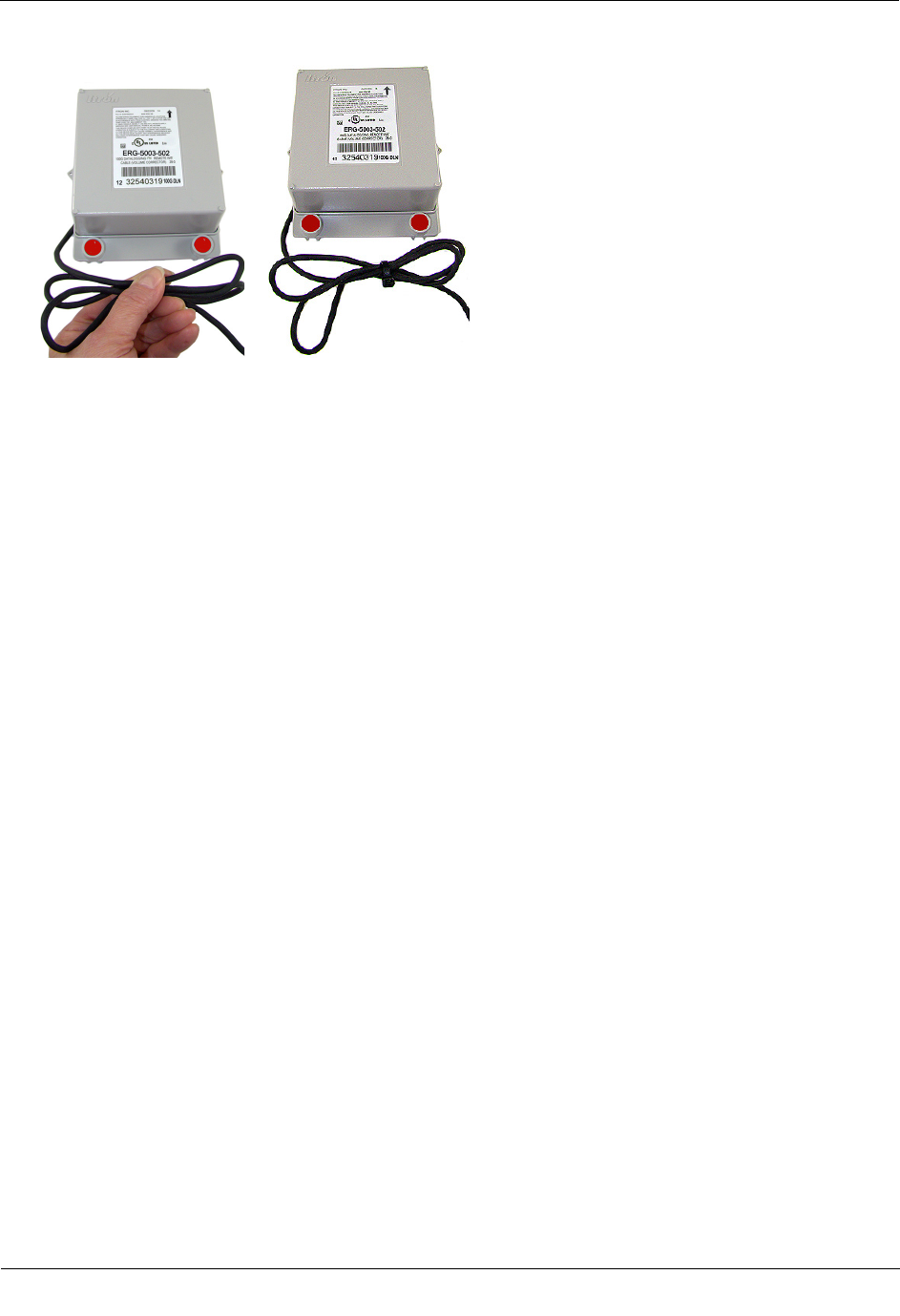
3. To reduce the risk of cable damage, secure the excess module cable with the cable ties from the Remote
Mount Installation Kit. Pull the cable tight. Remove and properly dispose the excess cable tie.
Mounting the 100G Series Remote Gas Module
TDC
-0824-006 100G Series Gas ERT Module Installation Guide, Remote Mount 17
Proprietary and Confidential
100G remote module installation on a vertical flat surface or wall is complete.
TDC
-0824-006 100G Series Gas ERT Module Installation Guide, Remote Mount 18
Proprietary and Confidential
This chapter provides the instructions to install the 100G series remote gas module on rotary gas meters.
Reference the Gas and Telemetry Module Meter Compatibility List (PUB-0117-002 or see the 100G Series
Remote ERT Module Meter Compatibility List on page 3 for rotary meters compatible with the 100G series
remote gas module.
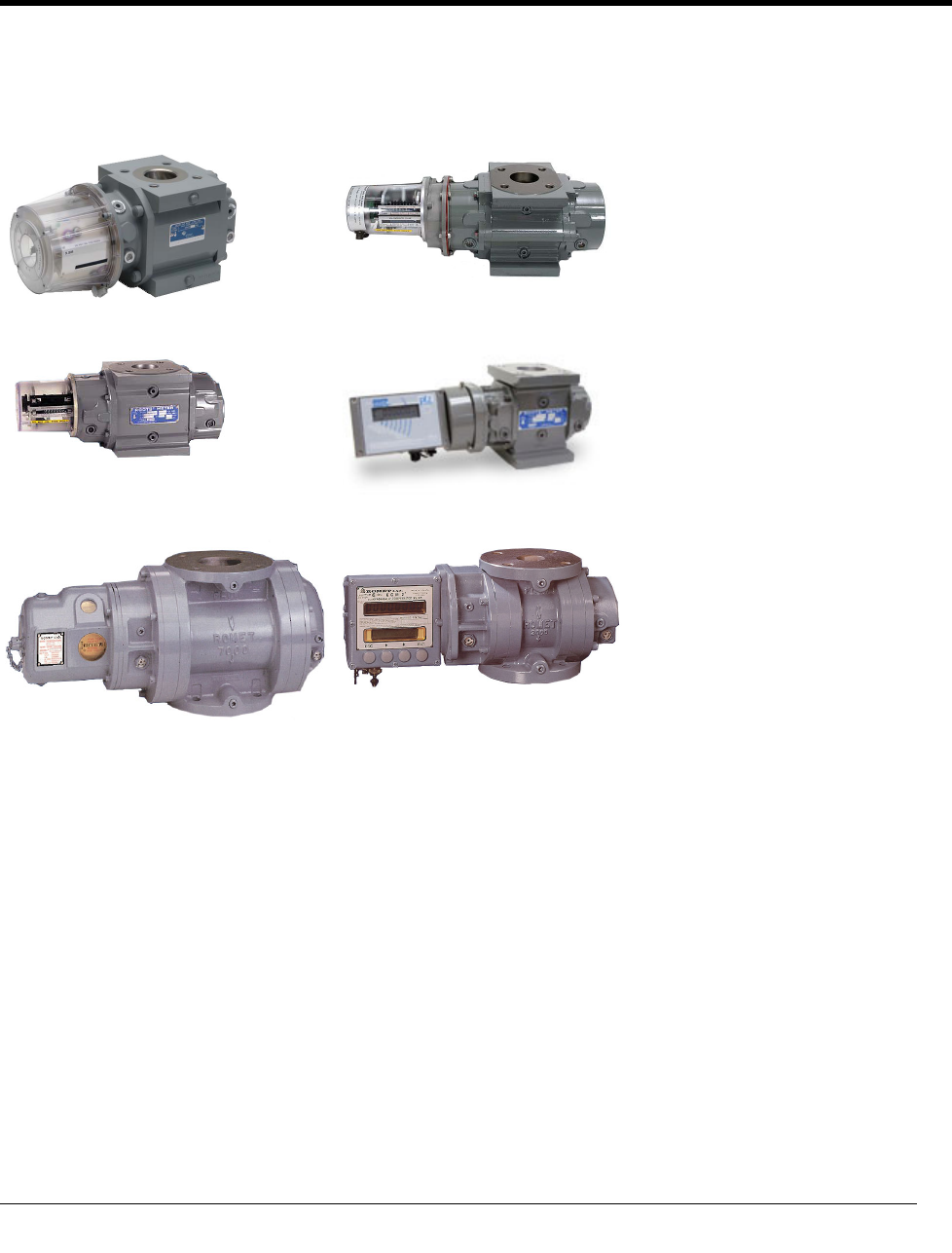
American rotary meter GE Dresser series LMMA rotary meter
GE Dresser series B3 meter GE Dresser IMC\W2 meter
Romet Imperial series RM meter Romet Imperial ECM2 meter
CHAPTER 3
R
otary Meter Installation
Rotary Meter Installation
TDC
-0824-006 100G Series Gas ERT Module Installation Guide, Remote Mount 19
Proprietary and Confidential
Required Installation Materials Available from Itron
The materials in the following table are required to install a remote 100G DLS module.
Itron Part Number
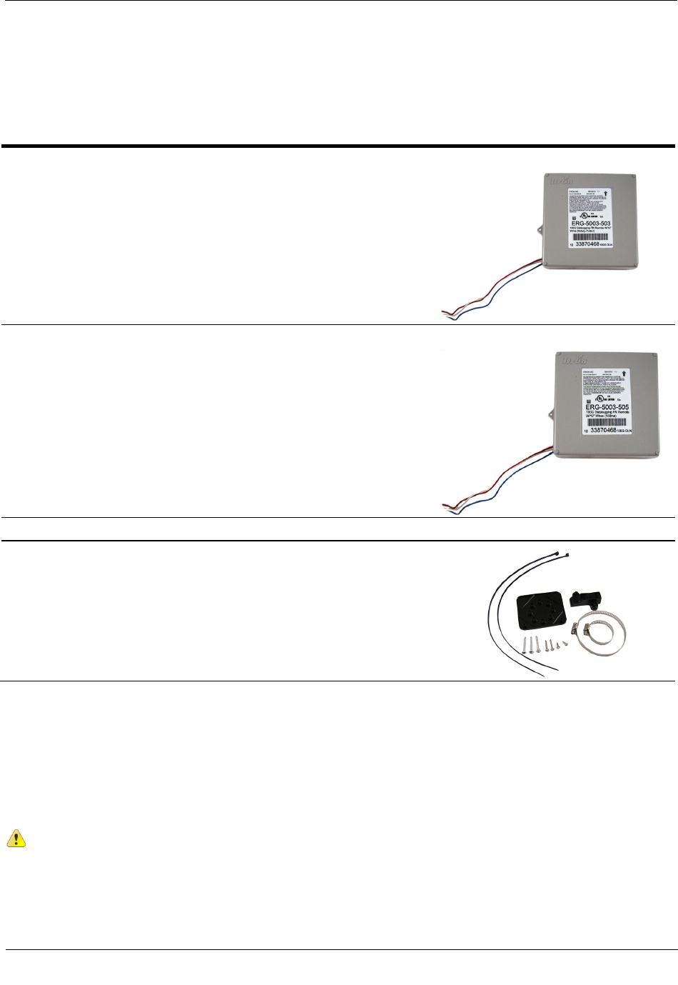
ERG-5003-503
ERG-5006-503
Note this remote ERT module comes standard with 12-inch lead wires and may
be shipped directly to the meter manufacturer for a factory-installed cable
(interface). The interface cable must be purchased directly from the meter
manufacturer.
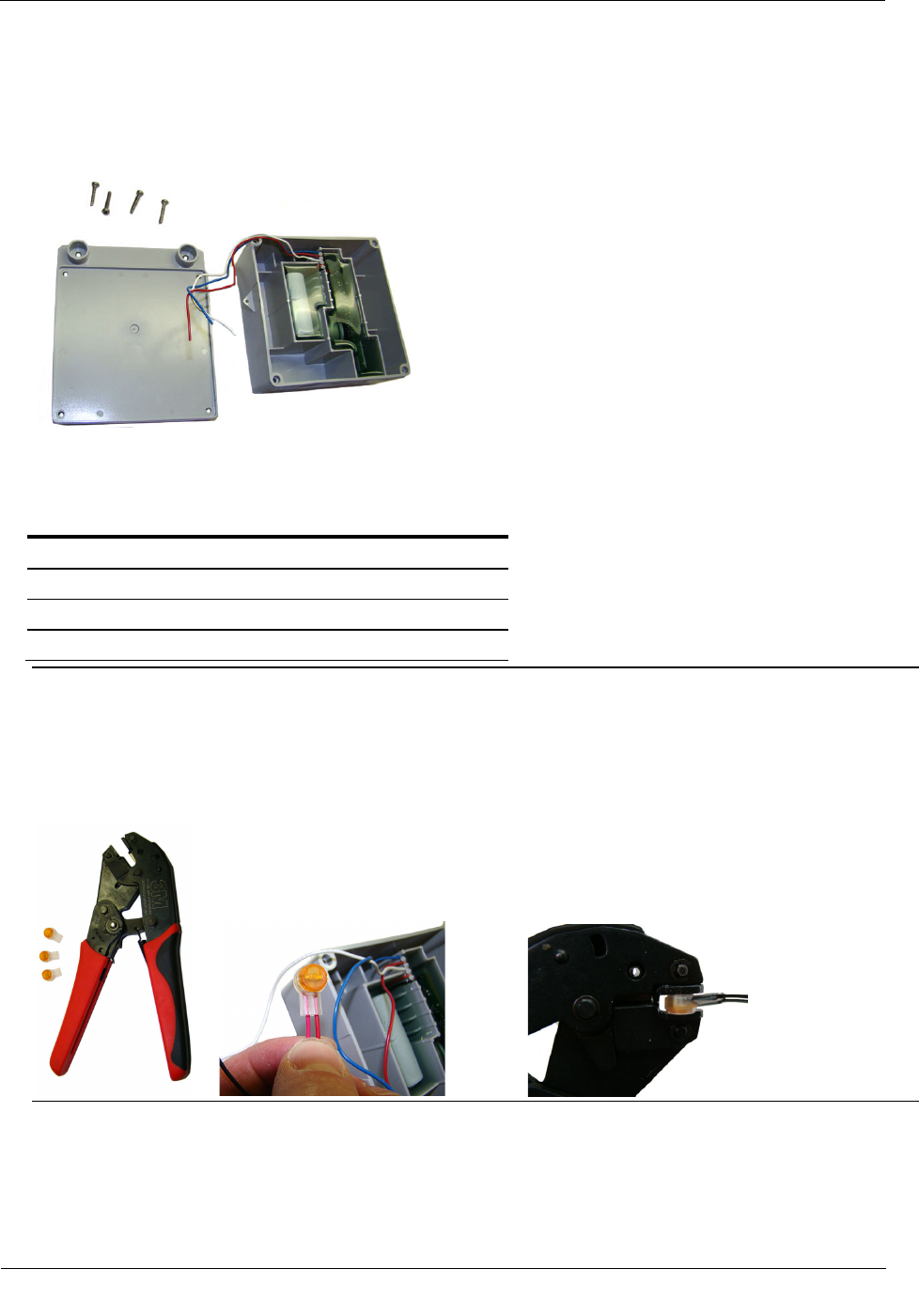
ERG-5003-505
ERG-5006-505
Note this remote ERT module comes standard with 12-inch lead wires and may
be shipped directly to the meter manufacturer for a factory-installed cable
(interface). The interface cable must be purchased directly from the meter
manufacturer.
Important You must purchase the interface cable directly from the meter manufacturer.
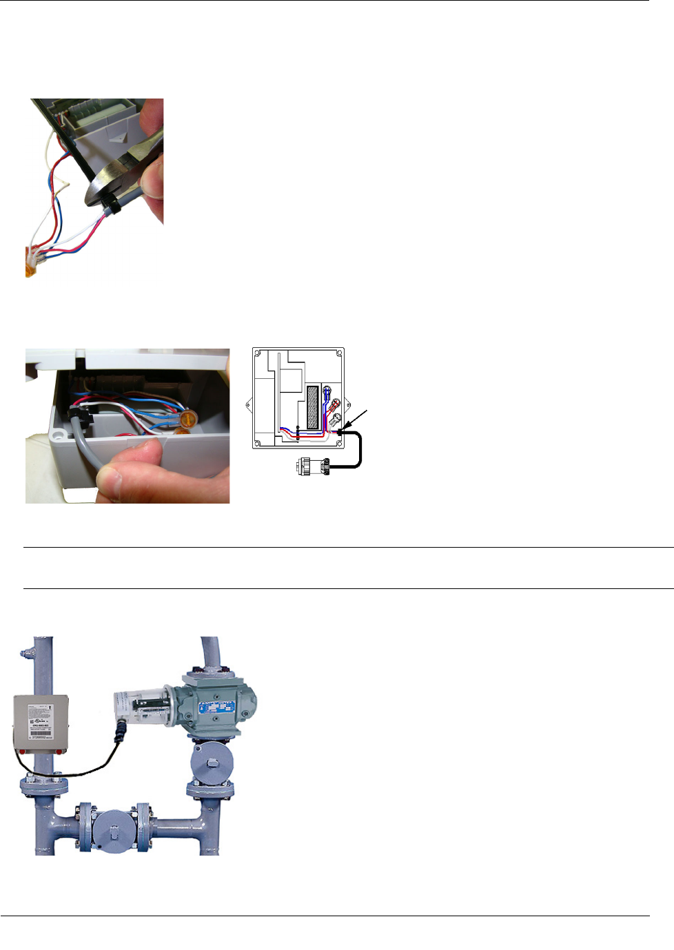
CFG-0005-003
Remote ERT Module Mounting Kit
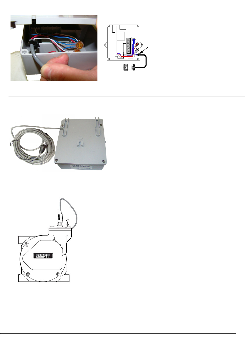
Connecting the 100G Remote Gas ERT Module to the GE
Dresser Rotary Meter Cable
You may ship the Itron 100G series remote gas module directly to GE Dresser for a factory-installed cable. If
you connect the module to the meter using an existing cable purchased from GE Dresser, complete the
following cable installation procedure.
Caution The purchased cable must have a mating connector compatible to the meter
receptacle. GE Dresser cables may be wired in different configurations for specific applications.
If necessary, contact GE Dresser for wiring diagrams for your specific application.
Rotary Meter Installation
TDC
-0824-006 100G Series Gas ERT Module Installation Guide, Remote Mount 20
Proprietary and Confidential
To connect the remote module to the rotary meter cable
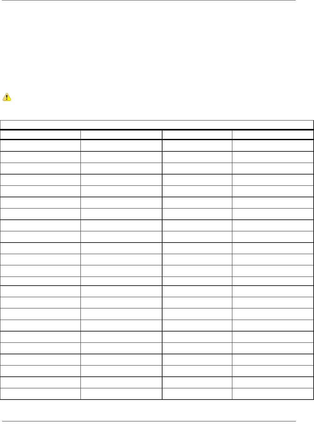
1. Remove the backplate (4 screws) from the remote module and expose the module lead wires. The
backplate and screws will be re-installed on the remote module later in this procedure so store them
(temporarily) in a safe, secure place.
2. Insert the lead wires from the remote module into new 3M gel connectors (Itron part number CON-0023-
001) together with the same colored lead wire from the meter cable (see the wiring table below) and crimp
using a 3M hand-held crimping tool.
Rotary Meter to Remote ERT Module Wire Table
Rotary meter wire Remote ERT module wire
Red Red
White White
Blue Blue
Important Use a crimping tool compatible with gel-connectors. Do not use a standard pliers for crimping
gel-connects. The crimping tool provides an even pressured crimp to make a secure connection. Apply
pressure for three seconds until the gel cap is fully crimped (collapsed) to allow time for the low viscosity
silicone-based gel to flow (3). If the silicone gel flows out of the crimped connector, avoid touching the
gel. Gel flowing from the connector provides environmental protection for the connection.
Note Do not strip lead wire prior to inserting the wire in the gel connector.
Rotary Meter Installation
TDC
-0824-006 100G Series Gas ERT Module Installation Guide, Remote Mount 21
Proprietary and Confidential
3. After completing the wiring connections, install a cable tie to the meter cable just below the exposed
colored lead wires on the cable insulation. Remove the excess cable tie using a hand-held sidecutter pliers.
The cable tie performs as a cable strain relief to mitigate the risk of destructive tension on the lead wires.
4. Tuck the three gel connectors and cable tie inside the module housing, as shown in the following
placement schematic illustration.
5. Install the remote 100G DLS module backplate using the four screws previously removed from the
module and a Torx T-15 screwdriver.
Important Verify the cable tie and gel connectors are inside the module housing and the cable extends
out of the slot in the backplate. Torque the backplate mounting screws to 9 to 12 inch-pounds.
6. Install the remote module on the wall or a pipe using the Remote Mount Kit (Itron part number CFG-
0005-003). For mounting instructions, see Mounting the 100G Series Gas ERT Module.
Rotary Meter Installation
TDC
-0824-006 100G Series Gas ERT Module Installation Guide, Remote Mount 22
Proprietary and Confidential
Programming the Remote ERT Module for GE Dresser Rotary
Meters
To program 100G series remote gas modules for use with GE Dresser rotary meters, use the meter drive rates
from the drive rate table in this section.
B3, LMMA & S3A CTR/TC Meter Drive Rates for Remote ERT Module
Programming
Caution Do not use these meter drive rates to program residential direct-drive or commercial
direct-drive modules. Use the information in the following tables to program 100G series remote
gas modules connected to GE Dresser rotary meters.
B3, LMMA, S3A CTR/TC Meter Drive Rates
B3 CTR Meter Size
B3 CTR Meter Pulse Rate
LMMA CTR Meter Size
LMMA CTR Meter Pulse Rate
8C 10 1.5M 10
11C 10 3M 10
15C 10 5M 10
2M 10 7M 10
3M 10 11M 10
5M 10 16M 100
7M 10 23M 100
11M 10 38M 100
16M 100 56M 100
23M 100 102M 100
38M 100
56M 100
LMMA CTR Meter Size
LMMA CTR Meter Pulse Rate
LMMA TC Meter Size
LMMA TC Meter Pulse Rate
1.5M 10 1.5M 10
3M 10 3M 10
5M 10 5M 10
7M 10 7M 10
11M 10 11M 10
16M 100 16M 100
23M 100
38M 100
56M 100
102M 100
Rotary Meter Installation
TDC
-0824-006 100G Series Gas ERT Module Installation Guide, Remote Mount 23
Proprietary and Confidential
Meters built 1/99 and beyond
Meters built prior to 1/99
B3 TC Meter Size
B3 TC Meter Pulse Rate
B3 TC Meter Size
B3 TC Meter Pulse Rate
8C 10 8C 50
11C 10 11C 50
15C 10 15C 50
2M 10 2M 50
3M 10 3M 50
5M 10 5M 50
7M 10 7M 50
11M 10 11M 50
16M 100 16M 500
S3A CTR Meter Size
S3A CTR Meter Pulse Rate
S3A TC Meter Size
S3A TC Meter Pulse Rate
1.5M 10 1.5M 10
3M 10 3M 10
5M 10 5M 10
7M 10 7M 10
11M 10 11M 10
16M 100 16M 100
Installing the Remote ERT Module to the Elster American Meter
RPM Series Rotary Meter
Some meter manufacturers provide ERT mounting kits and installation procedures for their meters. If 100G
series remote gas module to Elster American RPM meter installation instructions are not available, follow the
installation procedure in this section.
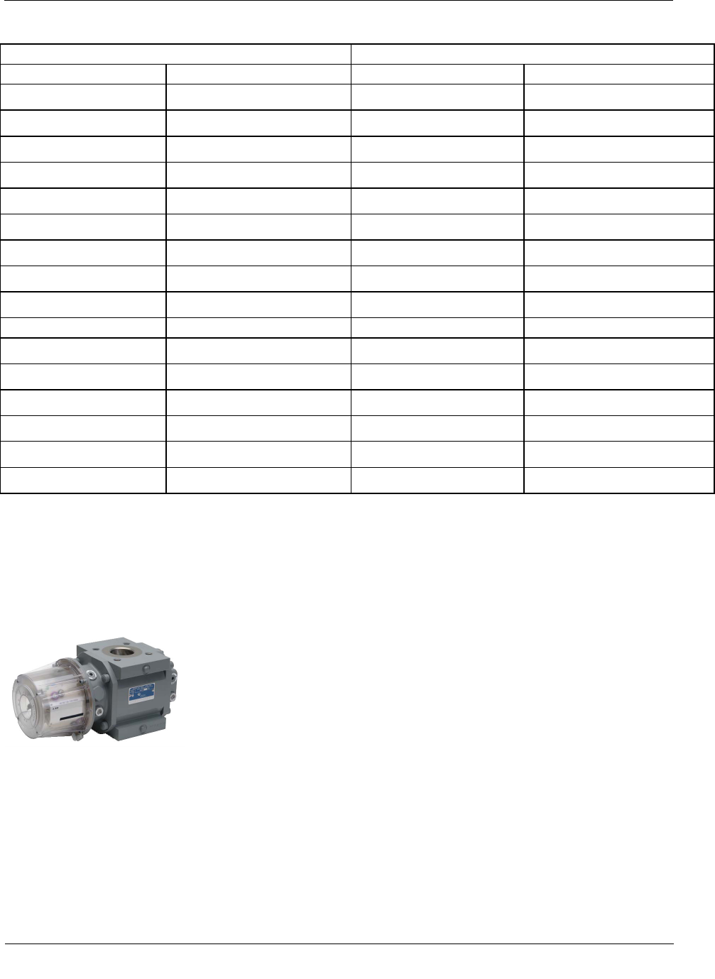
Elster American Meter RPM Series Rotary Meter
Rotary Meter Installation
TDC
-0824-006 100G Series Gas ERT Module Installation Guide, Remote Mount 24
Proprietary and Confidential
To install the 100G series remote gas module on an Elster American RPM series meter
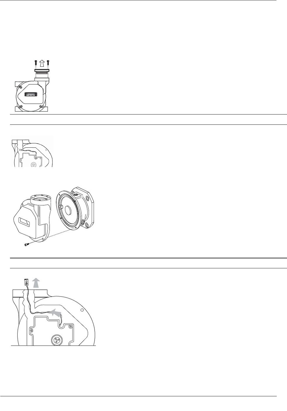
1. Remove the meter's top plate by removing the two 5mm screws and carefully prying up on the plate. The
plate is secured with an O-ring seal. Remove the O-ring from the plate.
Caution If the O-ring is damaged during removal, obtain a replacement from Elster American Meter Co.
2. Look into the meter tower and find the meter switch lead and connector (4-pin).
3. If the lead and connector are not visible or cannot be found, remove the four 5mm mounting screws and
the register cover. The meter switch lead and connector will be visible inside the cover.
4. Feed the lead and connector into the register cover tower.
Note Save any meter tags. You will re-install them later in the installation process.
5. If you removed the register cover, replace the cover using the four (4) 5mm mounting screws.
Rotary Meter Installation
TDC
-0824-006 100G Series Gas ERT Module Installation Guide, Remote Mount 25
Proprietary and Confidential
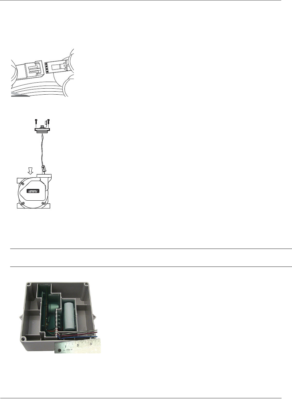
6. Attach the 4-pin male connector on the Elster American Meter adapter plate to the 4-pin female connector
inside the meter's tower. The connectors will slide together and latch.
7. Carefully push the connectors and wires into the meter tower housing.
8. Lubricate the O-ring with O-ring lubricant and install the O-ring on the adapter plate. Insert the adapter
plate into the tower and tighten the two 5 mm screws.
To connect the manufacturer cable to the ERT module
Note Connection to an Elster American Meter requires a cable interface compatible to an Elster
American Meter RPM rotary meter.
1. Trim the ERT module wires to 3.5 inches.
Rotary Meter Installation
TDC
-0824-006 100G Series Gas ERT Module Installation Guide, Remote Mount 26
Proprietary and Confidential
2. Carefully strip the insulation covering from the meter cable (purchased from the meter manufacturer)
approximately 1-1/2-inches from the end.
Caution Do not cut through the individual wire insulation.
3. Separate the black, white, and blue wires for connection to the 100G series remote gas module. Cut off the
unused wires even with the outer covering (insulation).
Caution Do not strip the individual wires.
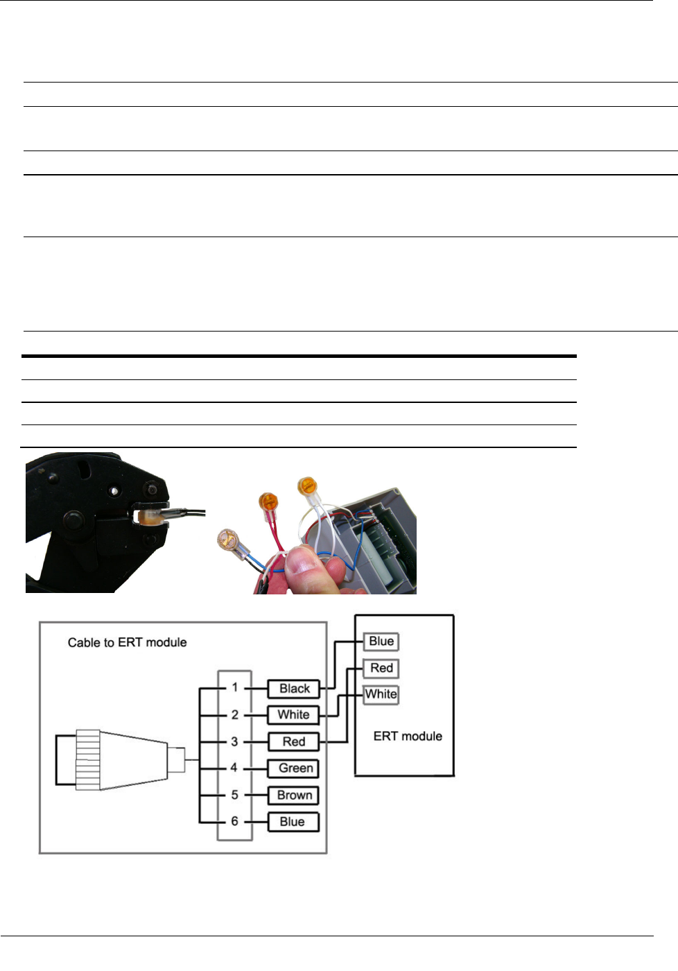
4. Connect the meter cable to the 100G series remote gas module using 3M gel-cap connectors. Follow the
wire connection table and wiring diagrams below. See Installation Prerequisites on page 7 for appropriate
3M crimping tools.
Important Use a crimping tool compatible with gel-connectors. Do not use a standard pliers for crimping
gel-connects. The crimping tool provides an even pressured crimp to make a secure connection. Apply
pressure for three seconds until the gel cap is fully crimped (collapsed) to allow time for the low viscosity
silicone-based gel to flow. If the silicone gel flows out of the crimped connector, avoid touching the gel.
Gel flowing from the connector provides environmental protection for the connection.
American RPM Meter to the 100G series remote gas module Wire Connections
American RPM Meter wire ERT module wire
Red Red
White White
Black Blue
5. Insert the meter cable through the slot on the ERT module backplate. Install a cable tie to the meter cable
wire below the meter cable insulation to provide strain relief.
Rotary Meter Installation
TDC
-0824-006 100G Series Gas ERT Module Installation Guide, Remote Mount 27
Proprietary and Confidential
6. Tuck the connectors and cable tie into the ERT module housing. Place backplate on the assembly and
tighten the four backplate screws using a size T-10 Torx screwdriver.
Important Verify the cable tie and gel connectors are inside the module housing and the cable extends
out of the slot in the backplate. Torque the backplate mounting screws to 9-12 inch-pounds.
To install the 100G series remote gas module cable
1. Insert the plug on the cable connected to the ERT module into the receptacle on the meter adapter plate.
2. Tighten the threaded collar on the plug onto the American Meter interface receptacle. Verify the
connection is hand-tight.

Rotary Meter Installation
TDC
-0824-006 100G Series Gas ERT Module Installation Guide, Remote Mount 28
Proprietary and Confidential
Mounting the 100G Series Remote Gas Module
Select an appropriate mounting location on adjacent piping close to the meter. Using the pipe bracket,
mounting plate and band clamps from the Remote Mount Kit (Itron part number CFG-0005-003), secure the
100G series remote gas module. Use the cable ties from the kit to secure any excess wire to the piping (see
Mounting the 100G DLS Remote Gas ERT Module on a Pipe on page 9).
Connecting the Remote ERT Module to the Romet Electronically
Compensated Meter (ECM2®)
The Romet ECM2® meter has three Form "A" outputs that can be configured at the factory to provide any
combination of the following three outputs:
• Uncorrected volume (UNC VOL)
• Corrected volume (COR VOL)
• Alarm
The pulse weight for the volumetric outputs is configured in SetUp Mode at Menu items > SET UNC OUT
and Menu items > SET COR OUT. Since Setup Mode is fully configurable, the ECM2® module is
universally adaptable to all Romet TC meter bodies. Reference the Romet technical manual for specific details
on the ECM2®.
Rotary Meter Installation
TDC
-0824-006 100G Series Gas ERT Module Installation Guide, Remote Mount 29
Proprietary and Confidential
Wiring the 100G Remote Gas ERT Module to the Romet ECM2®
Meter
Connect the correct interface wirings and set the output pulse spacing to complete remote module installation
with the Romet ECM2® meter. See the ECM2® interface wiring table below to complete wire connections.
Function
(+)UC
(-)UC
(+)CC
(-)CC
(+)ALM
(-)ALM
(+)Aux.CC
(-)Aux.CC
ERT Module wire
White and
Red
White and
Red
White and
Red
White and
Red
Pin location
for Cannon
Connector
Part
Number
34-125-20
C
B
A
B
E
D
34-125-40
A
B
C
D
E
F
34-125-41
A
B
C
D
E
F
34-125-42
E
F
A
B
C
D
34-125-43
A
B
E
F
C
D
34-125-44
A
B
34-125-45
A
B
E
D
C
F
34-125-50
3
1
2
5
6
4
34-125-51
3
1
2
5
6
4
Caution Set the ECM2® output pulse spacing to 750ms for operation with the remote 100G DLS module.
Output spacing represents an off-time between pulses.
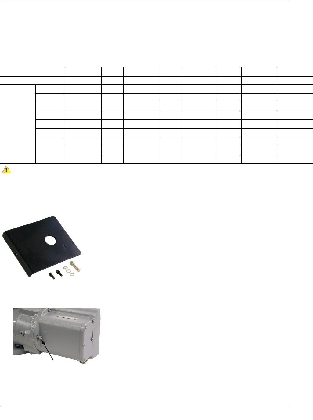
Romet ECM2/100G Remote Gas ERT Module Mounting Option
This mounting procedure requires the Romet ECM2/ERT Mounting Kit (Romet part number 34-444-1-KIT).
To mount the remote module on the Romet ECM2 meter
1. Remove the module screw from the back of the ECM2 meter and discard.
Rotary Meter Installation
TDC
-0824-006 100G Series Gas ERT Module Installation Guide, Remote Mount 30
Proprietary and Confidential
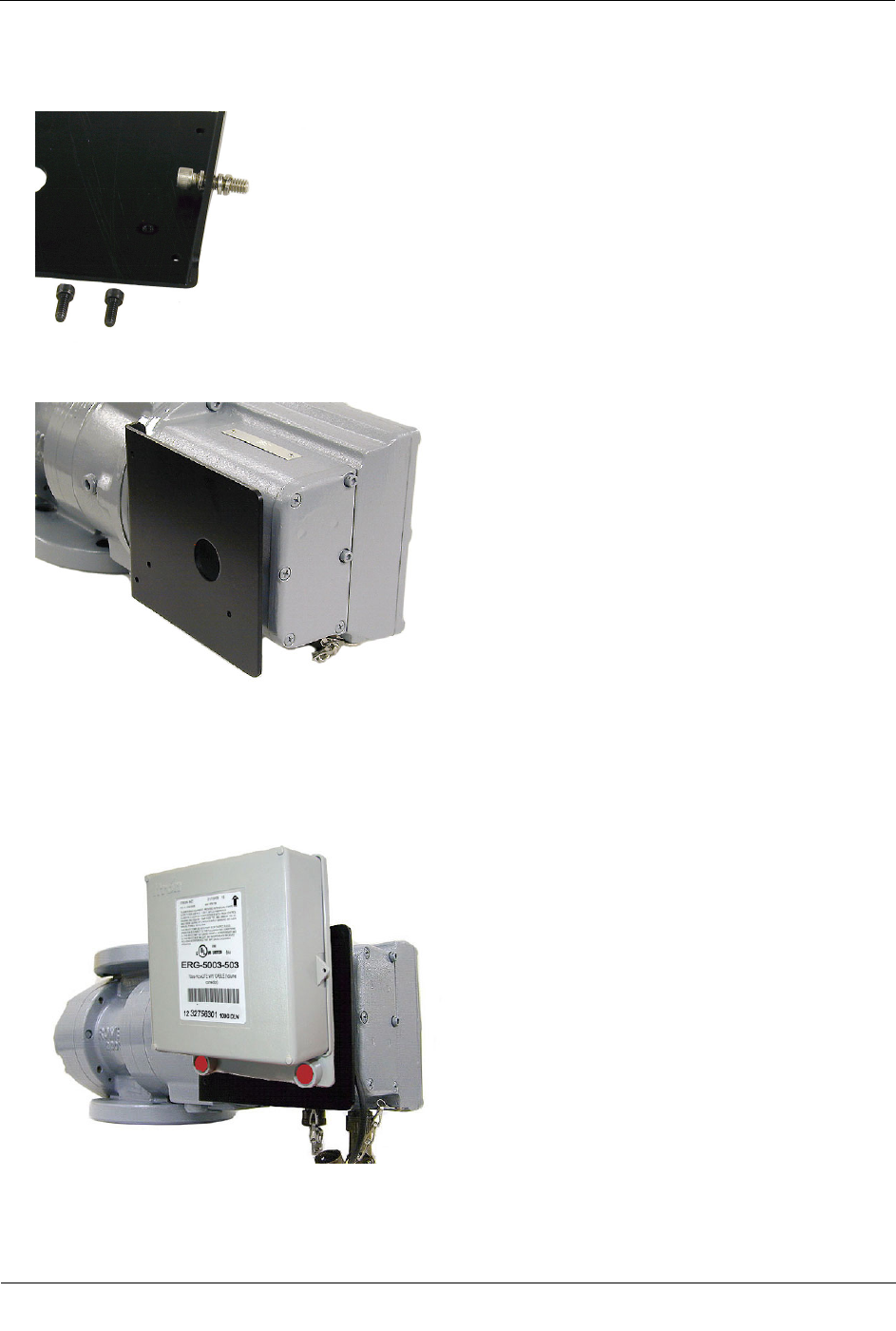
2. Insert the mounting screw fitted with the three lock washers. Two lock washers are used as spacers as
shown.
3. Attach the mounting plate to the meter. Insert the mounting screw where the module screw was removed.
Torque the mounting screw to 5-7 ft. lbs. to secure the plate to the Romet meter.
4. Mount the remote 100G module using the pre-drilled holes on the mounting plate and the module
mounting screws.
5. Place new tamper seals over the two screws. Press tamper seals into place using an 11/32-inch nut driver
or similar blunt tool.
6. Connect the module to the meter using the previously installed cable interface.
Rotary Meter Installation
TDC
-0824-006 100G Series Gas ERT Module Installation Guide, Remote Mount 31
Proprietary and Confidential
Programming the 100G Series Remote Gas Module
Caution You must program the 100G series remote gas module before use.
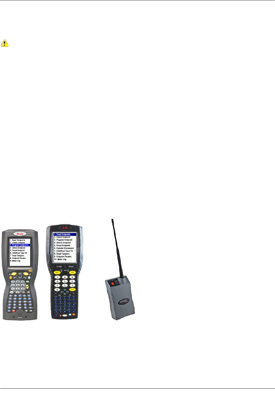
Program the 100G DLN ERT modules using:
• An FC200SR handheld computer with Field Deployment Manager (FDM) software version 1.1 or higher
or
• A FC300 with SRead handheld computer with Field Deployment Manager (FDM) software version 1.1 or
higher or
• A 900MHz Belt Clip Radio with Field Deployment Manager (FDM) software version 1.1 or higher and a
customer-supplied laptop. The Belt Clip Radio connects to the user-supplied laptop using a USB cable or
Bluetooth.
Program the 100G DLS ERT modules using:
• An FC200SR handheld computer with Field Deployment Manager (FDM) software version 3.3 or higher
or
• An FC300 with SRead handheld computer with Field Deployment Manager (FDM) software version 3.3
or higher or
• A 900MHz Belt Clip Radio with Field Deployment Manager (FDM) software version 3.3 or higher and a
customer-supplied laptop. The Belt Clip Radio connects to the user-supplied laptop using a USB cable or
Bluetooth.
See the Field Deployment Manager Endpoint Tools Mobile Application Guide (TDC-0934) for more complete
programming information.
FC200SR FC300 with SRead 900MHz Belt Clip Radio