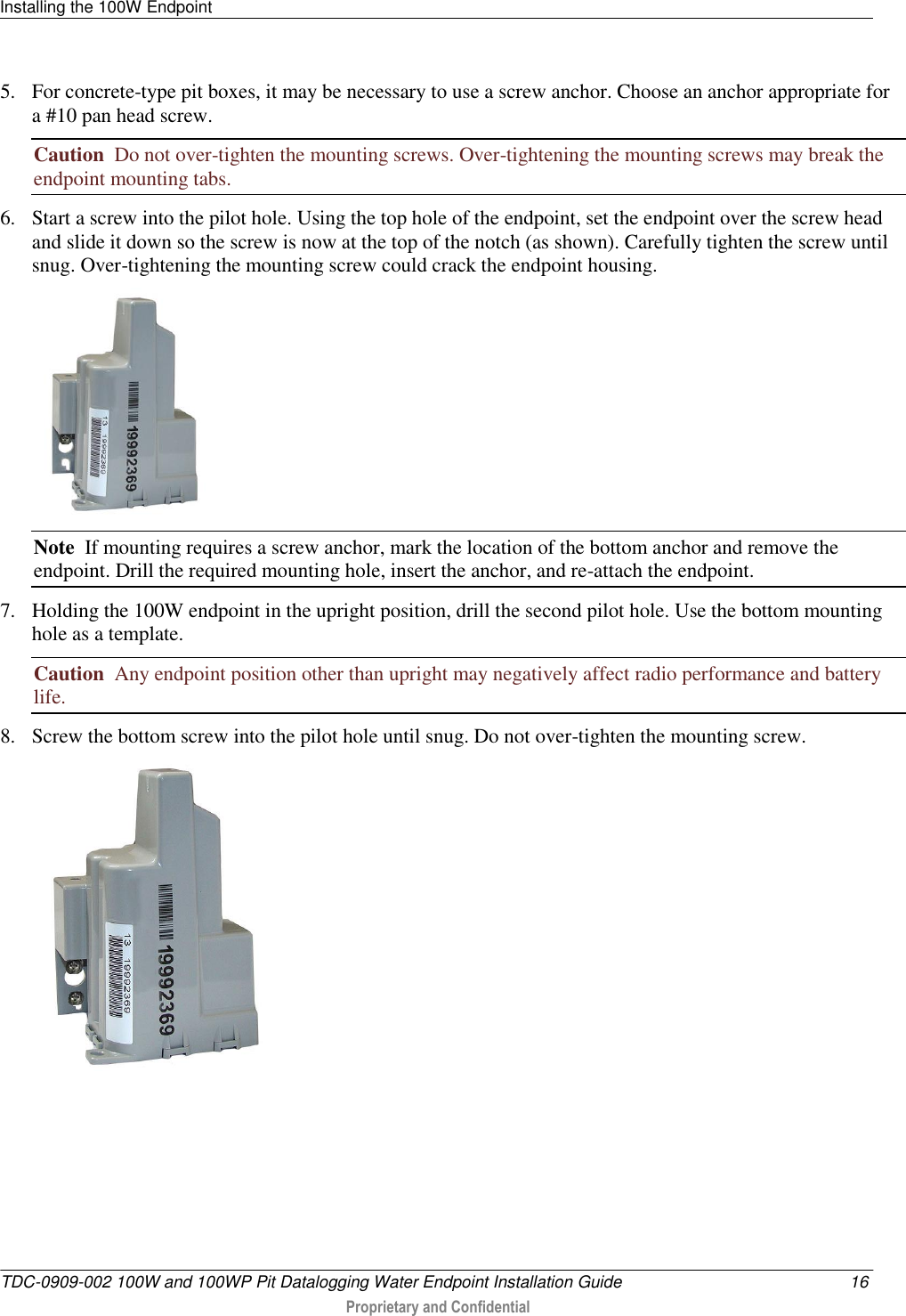
Itron 100WA AMR transceiver device for utility meters User Manual 1
Itron Inc AMR transceiver device for utility meters Users Manual 1
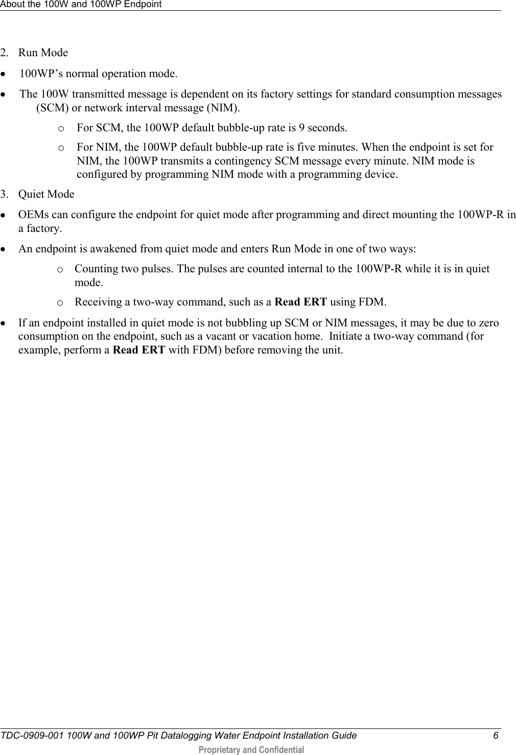
Itron >
Contents
- 1. Users Manual 1
- 2. Users Manual 2
- 3. Users Manual 3
- 4. Users Manual 4
- 5. Users Manual
- 6. Users Manual .1
- 7. Users Manual .2
- 8. Users Manual .1B
- 9. Users Manual .2B
Users Manual 1

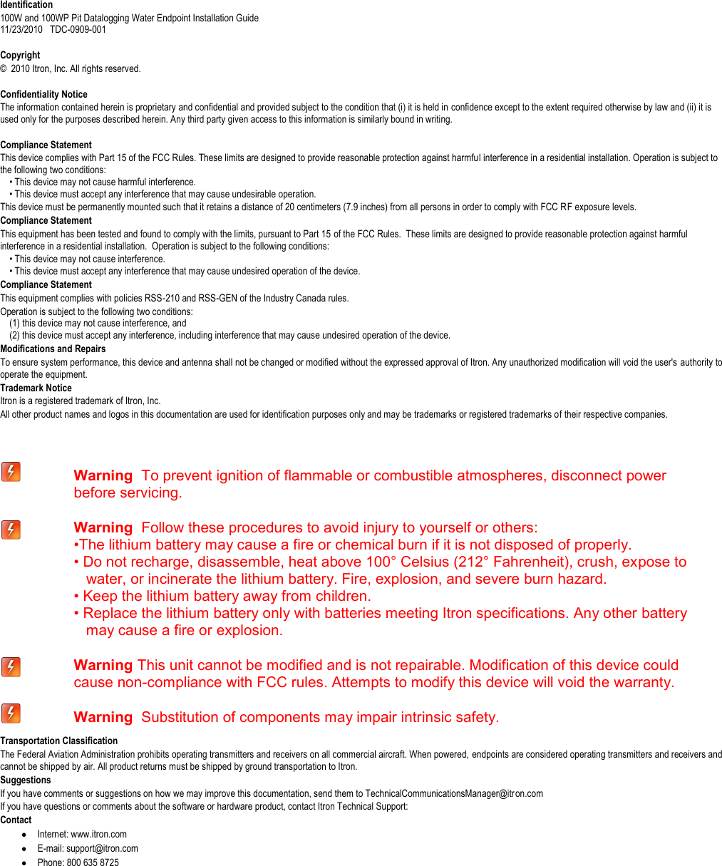
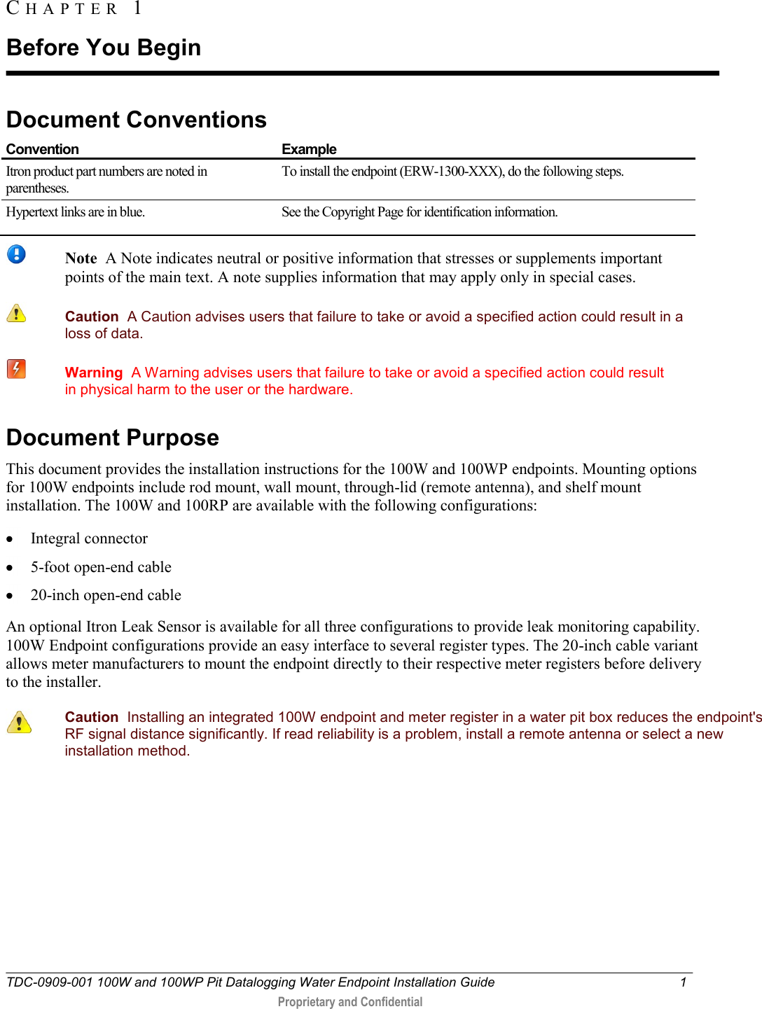
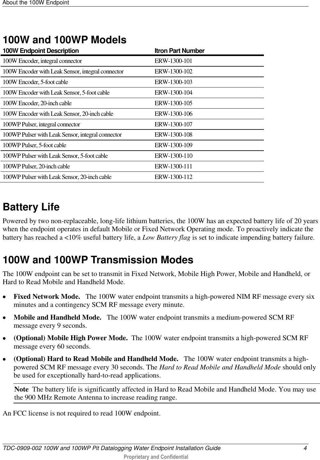
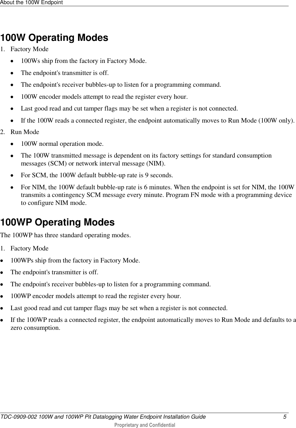
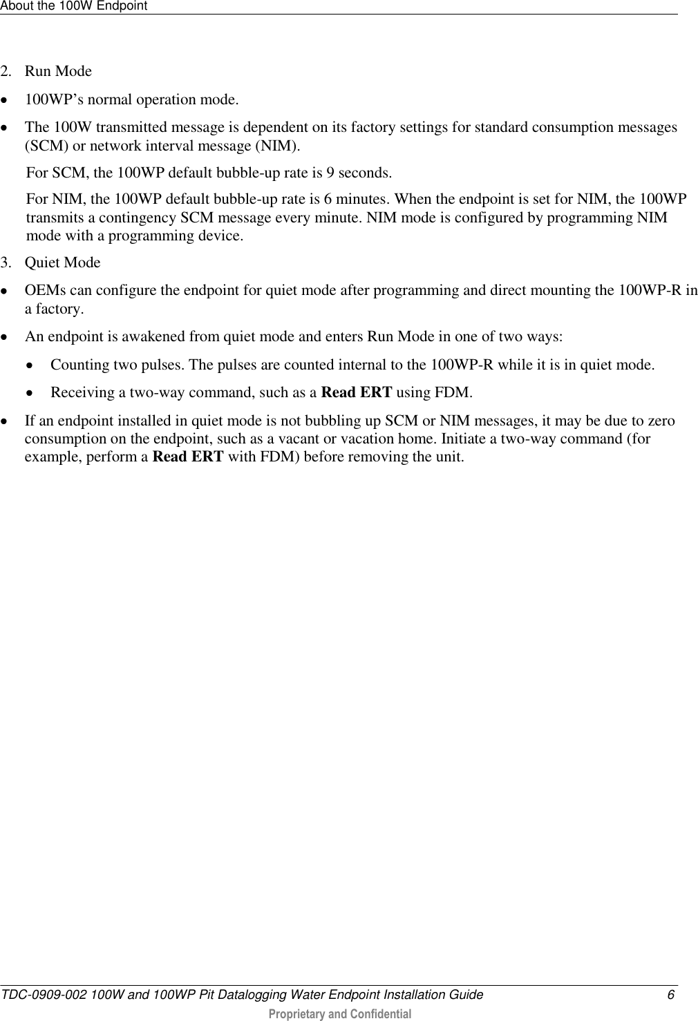
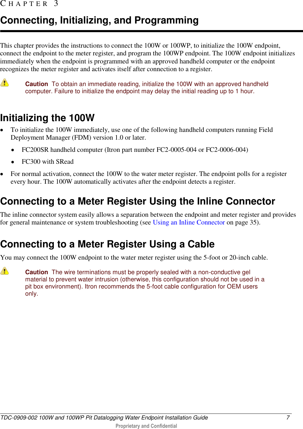
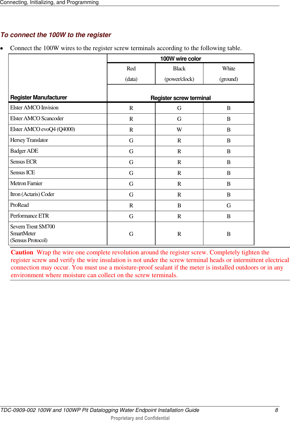
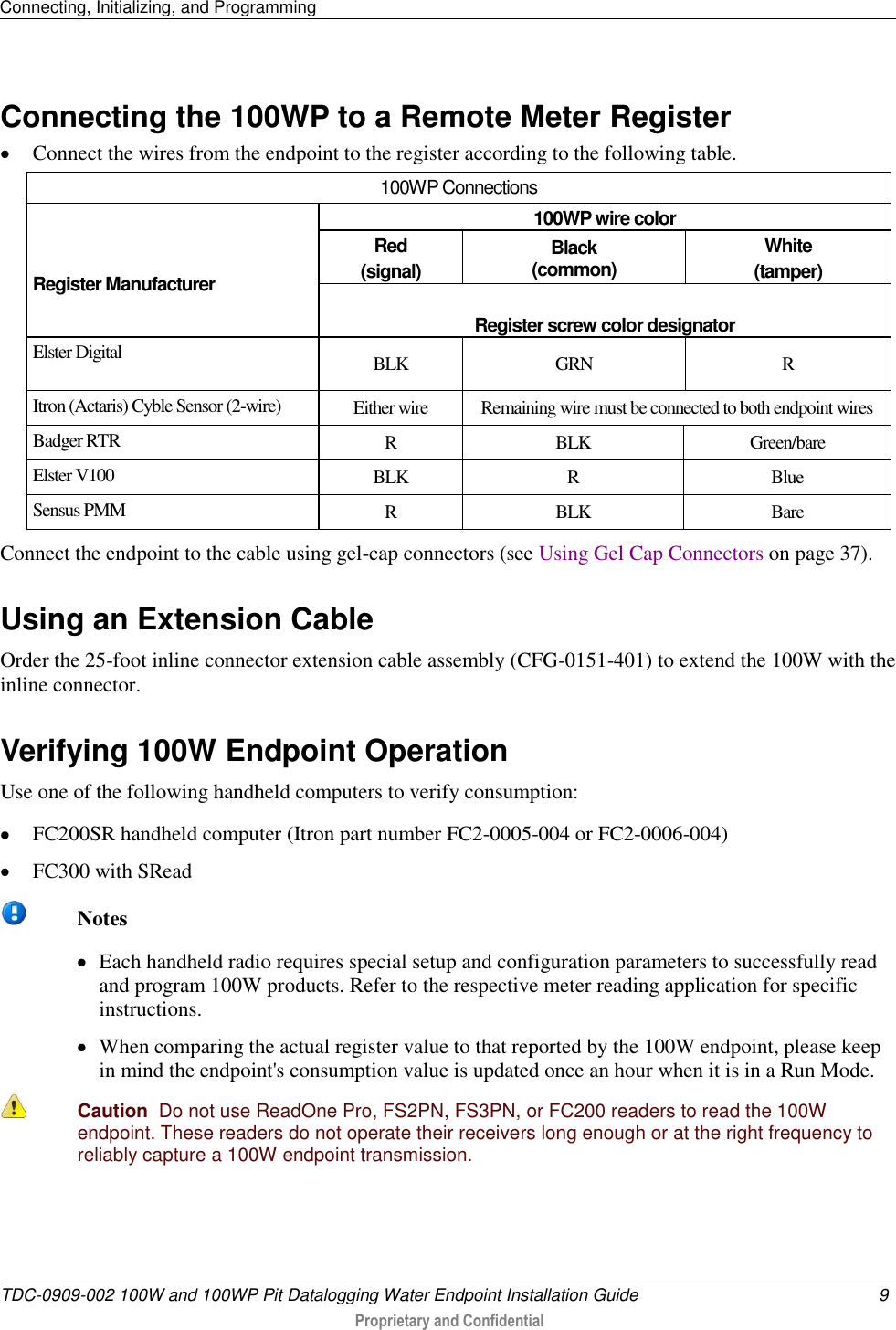
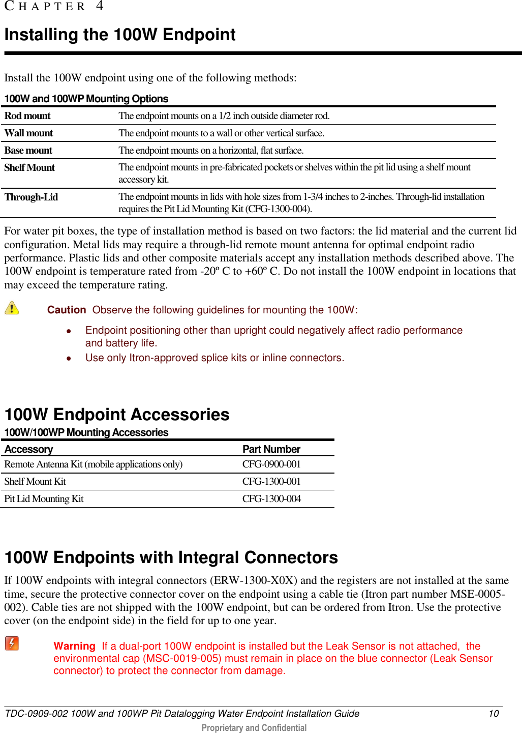
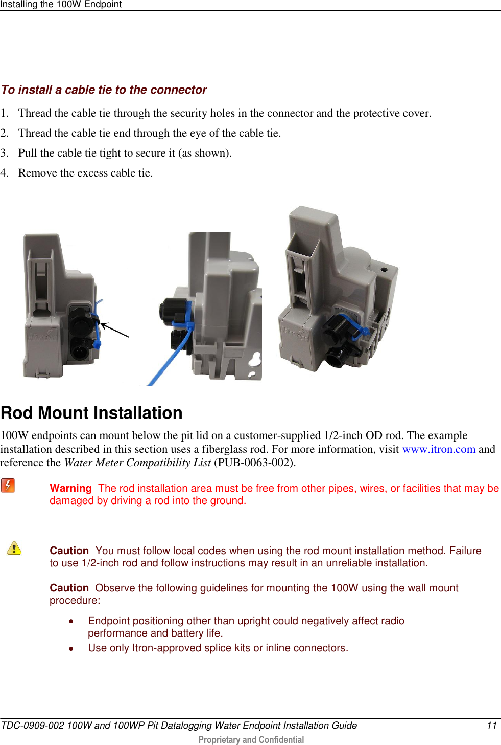
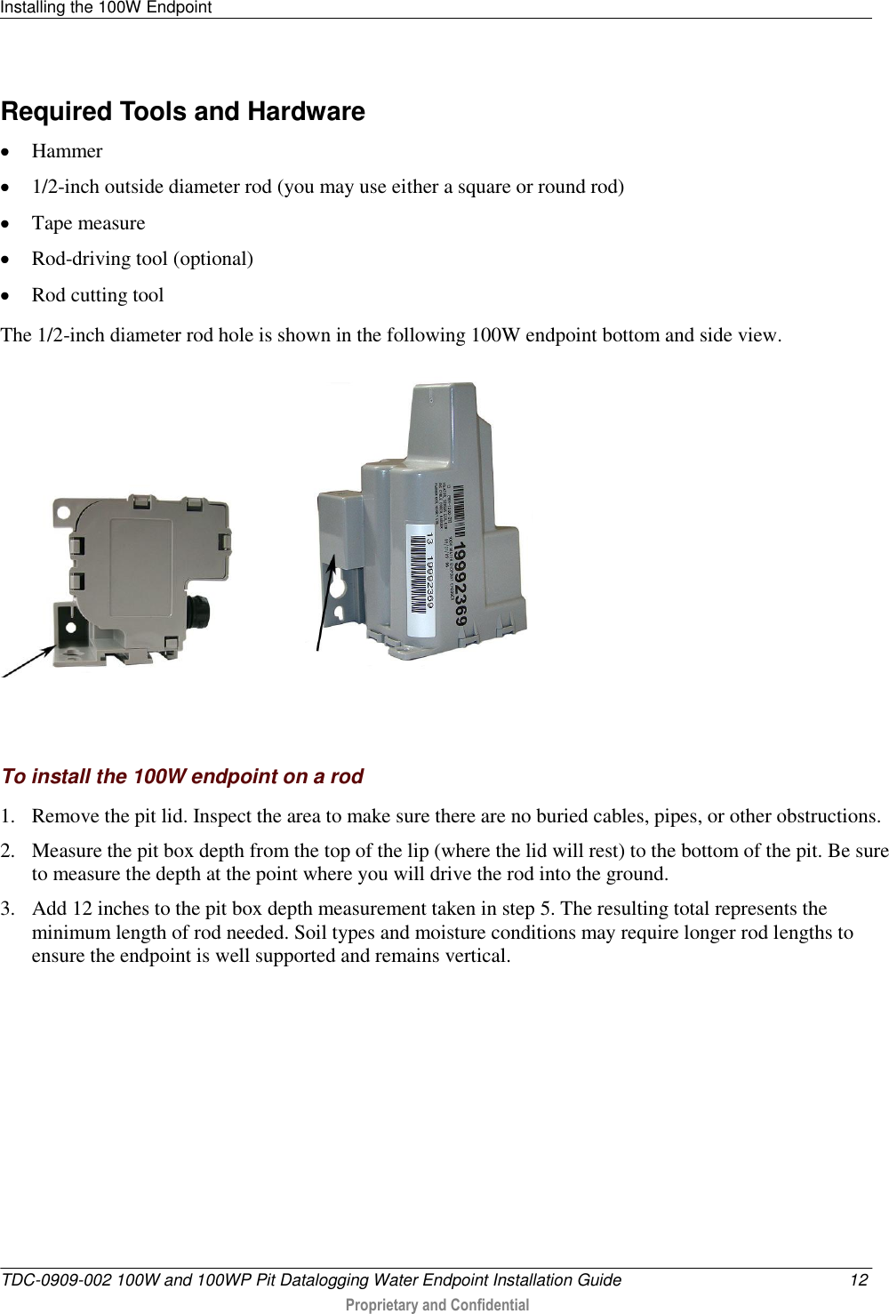
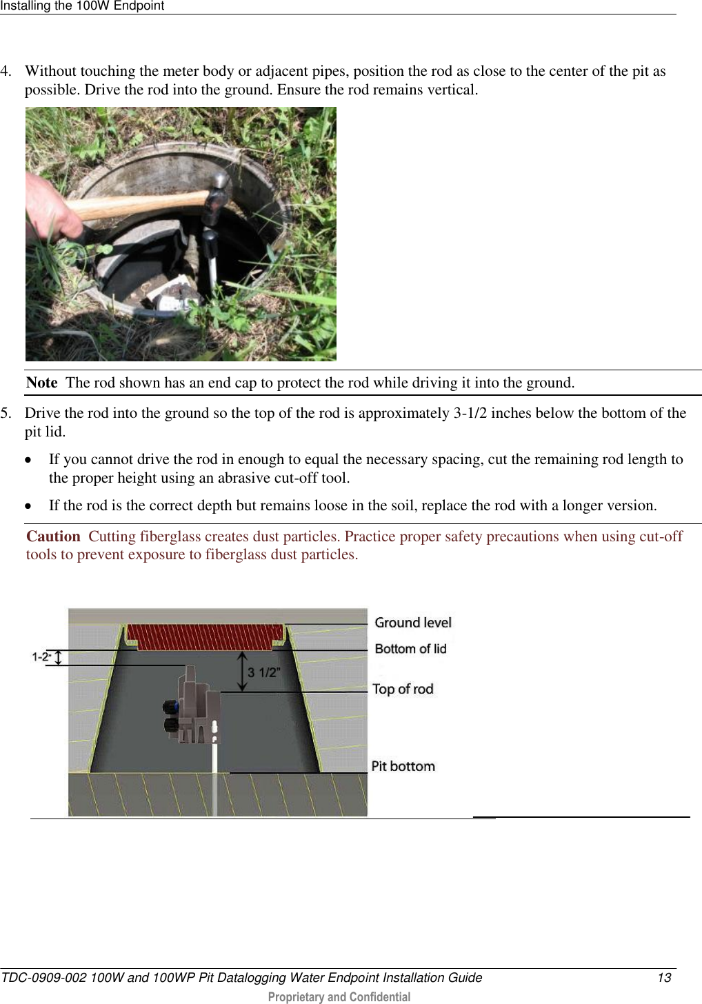
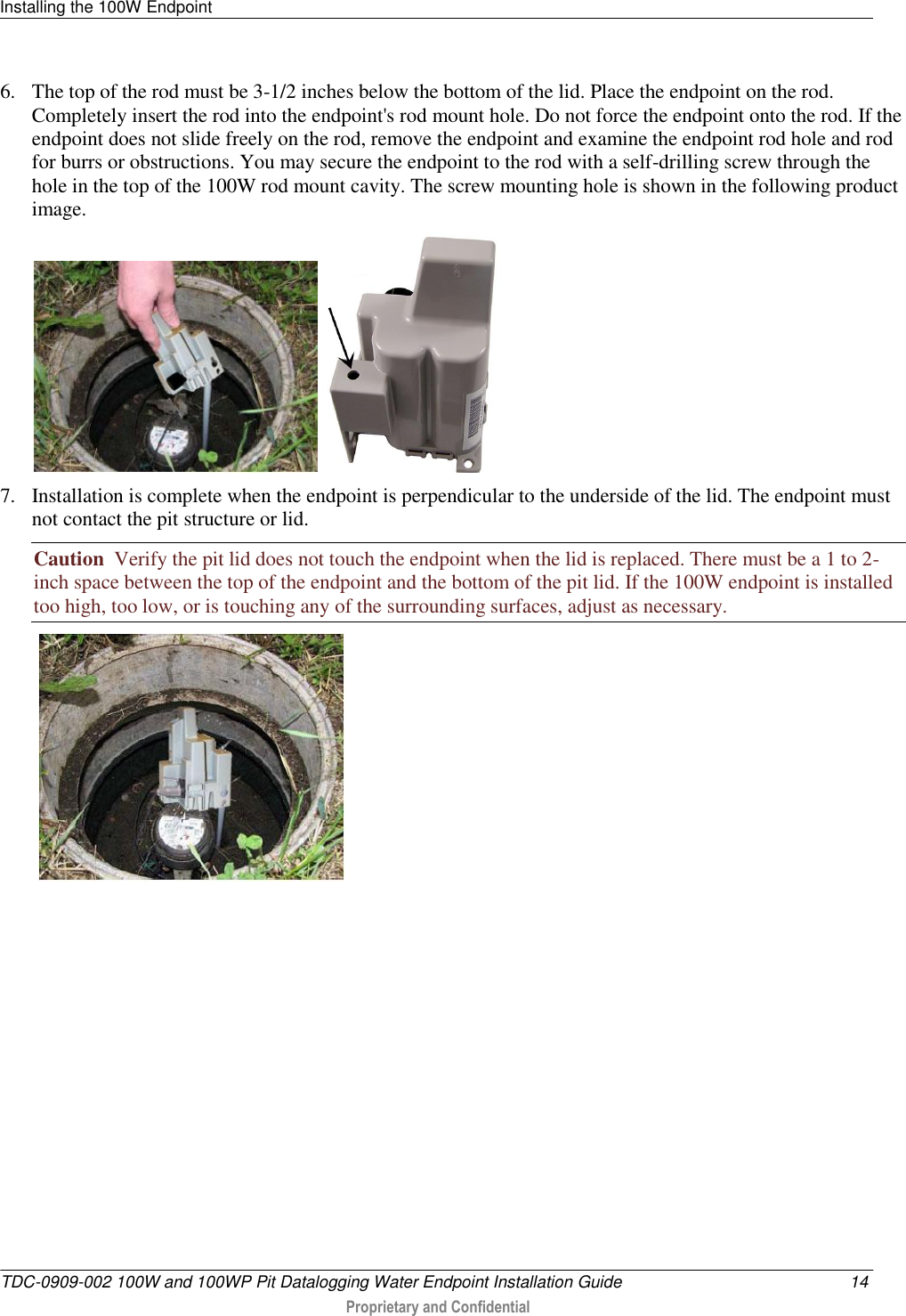
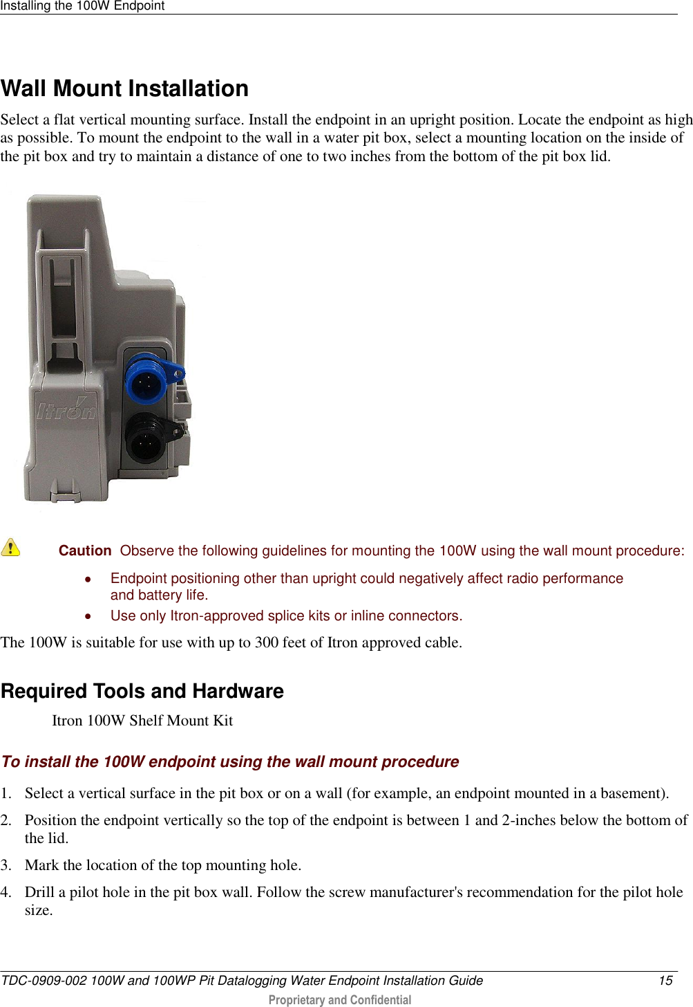
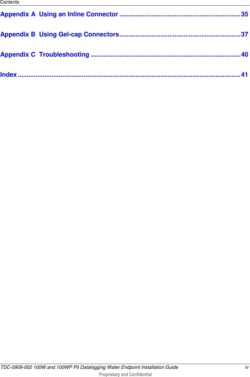
![TDC-0909-001 100W and 100WP Pit Datalogging Water Endpoint Installation Guide 3 Proprietary and Confidential The 100W Endpoints are high-power radio frequency automatic meter reading (AMR) devices that attach to water registers to collect consumption usage and tamper data the endpoint then transmits to a data collection device. The endpoint operates in both bubble-up mode and two-way modes. The 100W Endpoints ship in Factory Mode. The endpoints acquire and transmit meter register data within one hour following register connection. The endpoint transfers meter data immediately if the unit is initialized with a handheld computer during installation (see Initializing the 100W on page 7). Caution Failure to initialize the endpoint may delay the initial reading up to 1 hour. The 100W endpoint will default to a consumption value of 0 if the endpoint is not programmed with Itron's Field Deployment Manager (FDM). The 100W Endpoint supports protocols for a variety of meter manufacturer's registers. Refer to the Water Meter Compatibility List (PUB-0063-002), for the list of supported meters and registers. 100W Endpoints feature the following capabilities: Leak Detection and Reverse Flow Detection. 100W endpoints feature the same robust features as Itron's 60 series water endpoints to provide Leak Detection and Reverse Flow Detection. For more information about Leak Detection and Reverse Flow Detection, see the Itron white paper Detecting Leaks and Reverse Flow with 60 Series Endpoints https://extranet-kc.itron.com/Water%20Endpoints/Detecting%20Leaks%20and%20Reverse%20Flow%20with%2060%20Series%20Endpoints.pdf. Communication Error Indicators. Last Good Read. The cable is cut. Note Last Good Read may be an indicator of a damaged register. Extended Cut Cable. The Last Good Read flag was set in the last 24 hours (Fixed Network [FN] mode) or the last 40 days (Mobile Mode). CH A P T E R 2 About the 100W and 100WP Endpoint](https://usermanual.wiki/Itron/100WA.Users-Manual-1/User-Guide-1380869-Page-7.png)
Users Manual .1

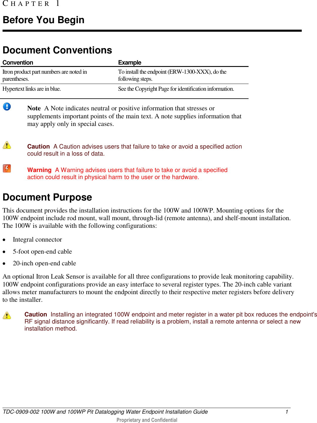
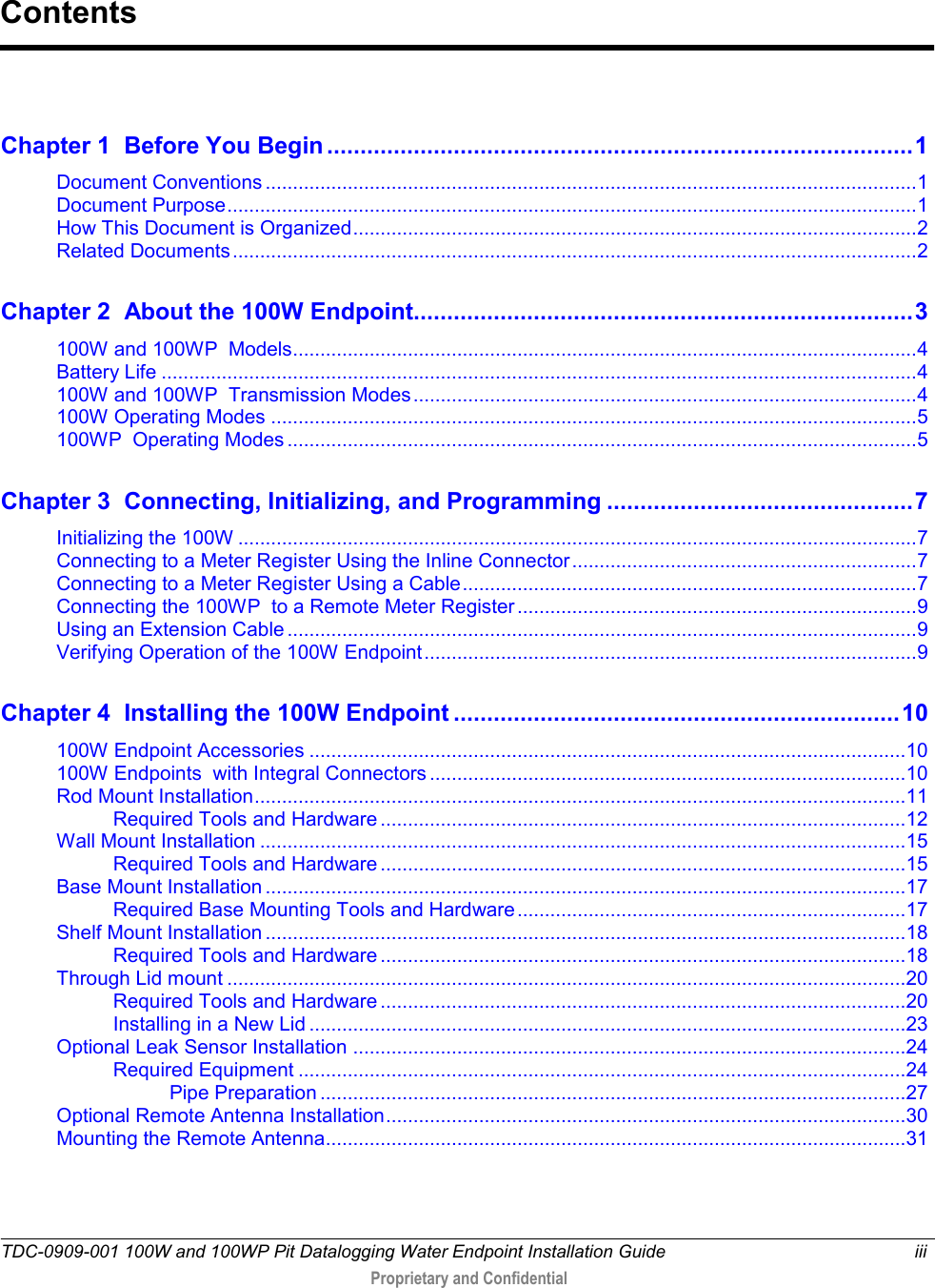
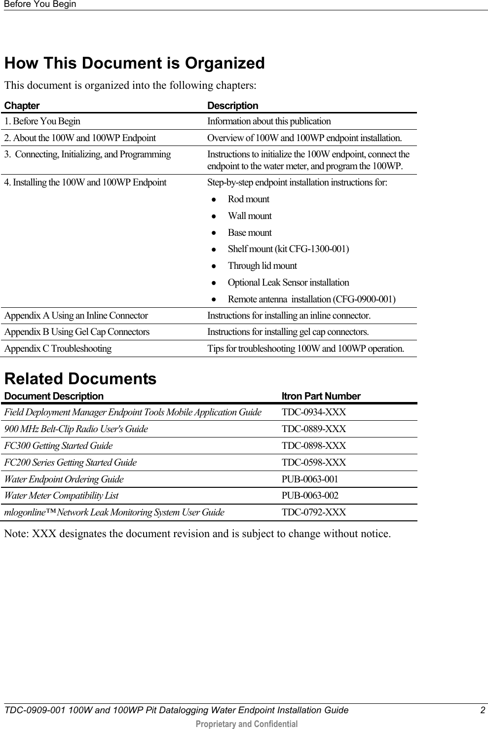
![TDC-0909-002 100W and 100WP Pit Datalogging Water Endpoint Installation Guide 3 Proprietary and Confidential The 100W endpoints are high-power radio frequency automatic meter reading (AMR) devices that attach to water registers to collect consumption usage and tamper data the endpoint then transmits to a data collection device. The endpoint operates in both bubble-up mode and two-way modes. The 100W endpoints ship in Factory Mode. The endpoints acquire and transmit meter register data within one hour following register connection. The endpoint transfers meter data immediately if the unit is initialized with a handheld computer during installation (see Initializing the 100W Endpoint on page 6). Caution Failure to initialize the endpoint may delay the initial reading up to 1 hour. The 100W endpoint will default to a consumption value of 0 if the endpoint is not programmed with Itron's Field Deployment Manager (FDM). The 100W endpoint supports protocols for a variety of meter manufacturer's registers. Refer to the Water Meter Compatibility List (PUB-0063-002), for the list of supported meters and registers. 100W endpoints feature the following capabilities: Leak Detection and Reverse Flow Detection. 100W endpoints feature the same robust features as Itron's 60 series water endpoints to provide Leak Detection and Reverse Flow Detection. For more information about Leak Detection and Reverse Flow Detection, see the Itron white paper Detecting Leaks and Reverse Flow with 60 Series Endpoints see https://extranet-kc.itron.com/Water%20Endpoints/Detecting%20Leaks%20and%20Reverse%20Flow%20with%2060%20Series%20Endpoints.pdf. Communication Error Indicators. Last Good Read. The cable is cut. Note Last Good Read may be an indicator of a damaged register. Extended Cut Cable. The Last Good Read flag was set in the last 24 hours (Fixed Network [FN] mode) or the last 40 days (Mobile Mode). CH A P T E R 2 About the 100W Endpoint](https://usermanual.wiki/Itron/100WA.Users-Manual-1/User-Guide-1436046-Page-7.png)