Itron 100WA AMR transceiver device for utility meters User Manual 2
Itron Inc AMR transceiver device for utility meters Users Manual 2
Itron >
Contents
- 1. Users Manual 1
- 2. Users Manual 2
- 3. Users Manual 3
- 4. Users Manual 4
- 5. Users Manual
- 6. Users Manual .1
- 7. Users Manual .2
- 8. Users Manual .1B
- 9. Users Manual .2B
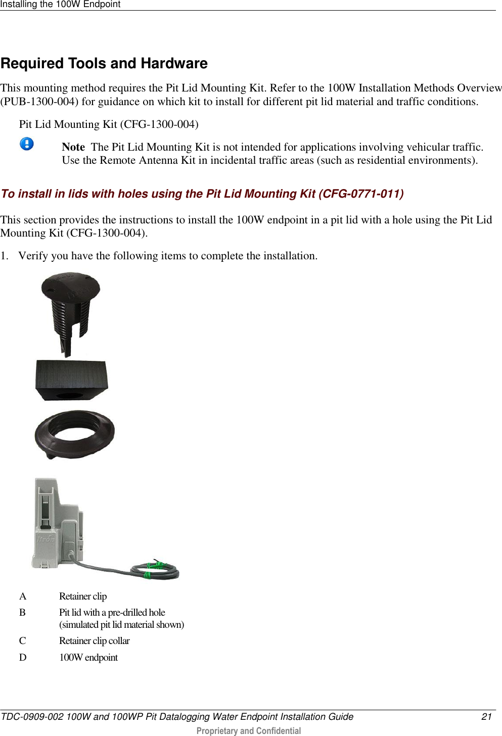
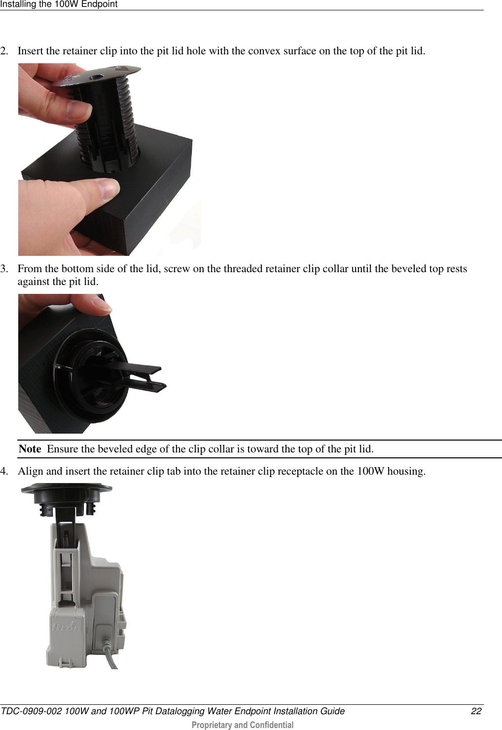
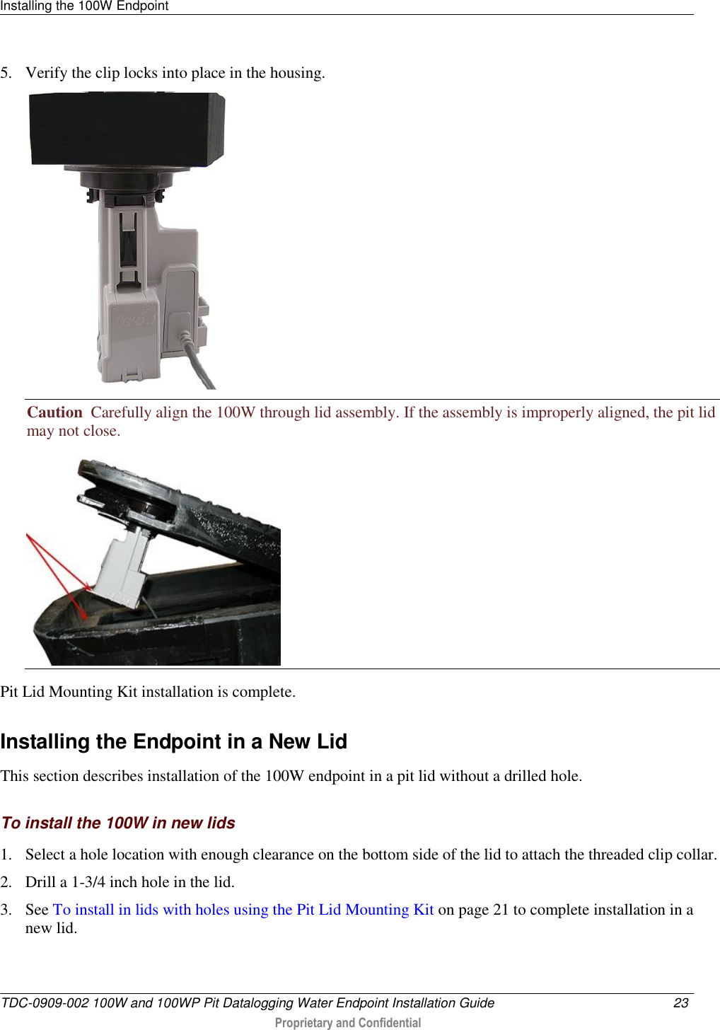
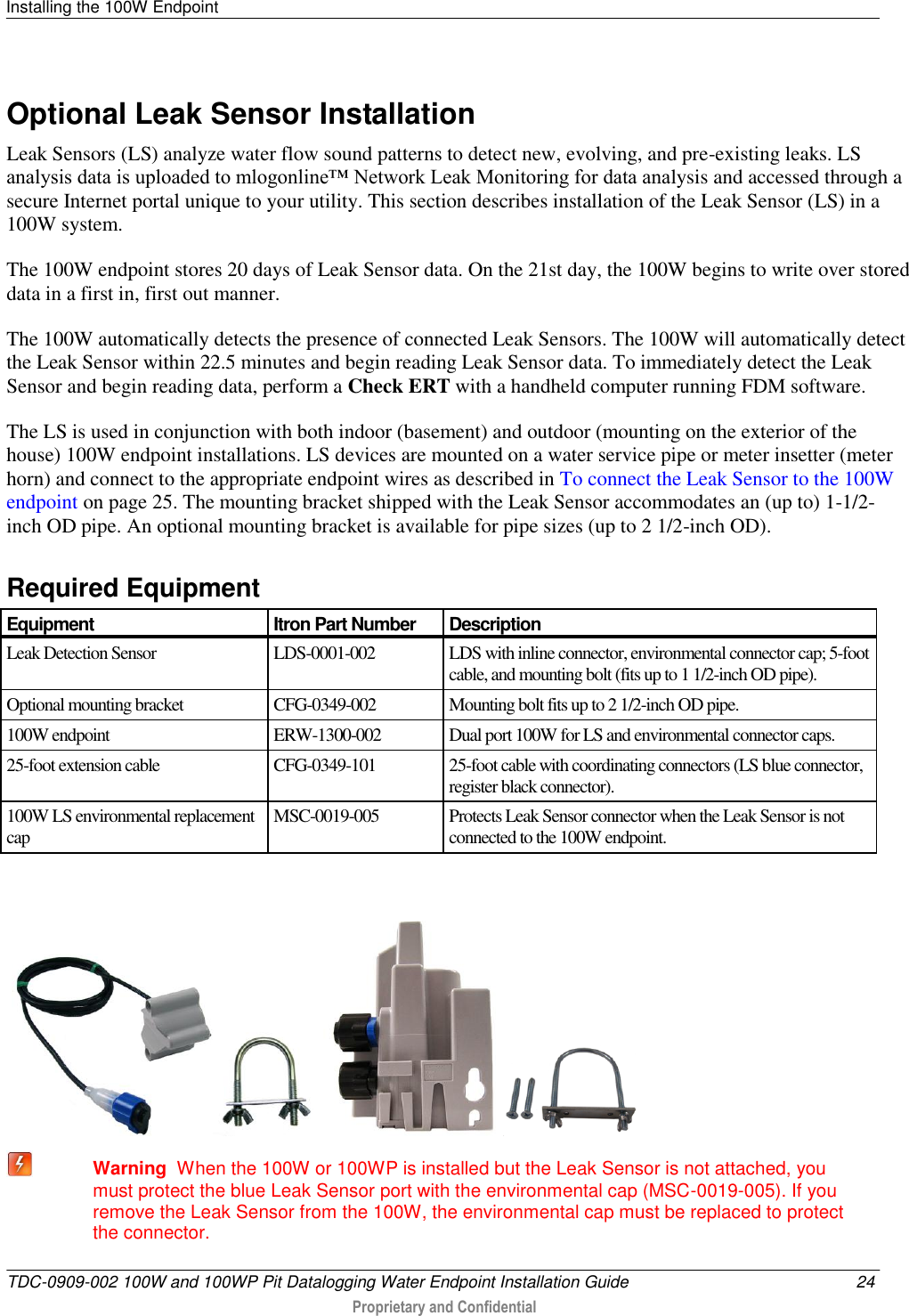
Users Manual 2
Users Manual .2