Itron 100WA AMR transceiver device for utility meters User Manual 2
Itron Inc AMR transceiver device for utility meters Users Manual 2
Itron >
Contents
- 1. Users Manual 1
- 2. Users Manual 2
- 3. Users Manual 3
- 4. Users Manual 4
- 5. Users Manual
- 6. Users Manual .1
- 7. Users Manual .2
- 8. Users Manual .1B
- 9. Users Manual .2B
Users Manual 2

TDC-0909-001 100W and 100WP Pit Datalogging Water Endpoint Installation Guide 10
Proprietary and Confidential
Install the endpoint using one of the following methods:
100W and 100WP Mounting Options
Rod mount
The endpoint mounts on a 1/2 inch outside diameter rod.
Wall mount
The endpoint mounts to a wall or other vertical surface.
Base mount
The endpoint mounts on a horizontal, flat surface.
Shelf mount
The endpoint mounts in pre-fabricated pockets or shelves within the pit lid using a
shelf mount accessory kit.
Through lid
The endpoint mounts in lids with hole sizes from 1 3/4 inches to 2 inches.
Through lid installation requires the Pit Lid Mounting Kit (CFG-1300-004).
For water pit boxes, the type of installation method is based on two factors: the lid material and the current lid
configuration. Metal lids may require a through-lid remote mount antenna for optimal endpoint radio
performance. Plastic lids and other composite materials accept any installation methods described above. The
100W Endpoint is temperature rated from -20º C to +60º C. Do not install the 100W Endpoint in locations that
may exceed the temperature rating.
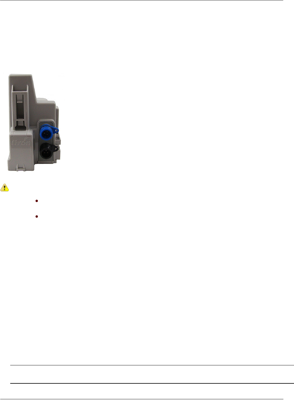
Caution Observe the following guidelines for mounting the 100W:
Endpoint positioning other than upright could negatively affect radio performance and
battery life.
Use only Itron-approved splice kits or inline connectors.
100W and 100WP Endpoint Accessories
100W/100WP Mounting Accessories
Accessory
Part Number
Remote Antenna Kit (Mobile Applications Only)
CFG-0900-001
Shelf Mount Kit
CFG-1300-001
Pit Lid Mounting Kit
CFG-1300-004
100W and 100WP Endpoints with Integral Connectors
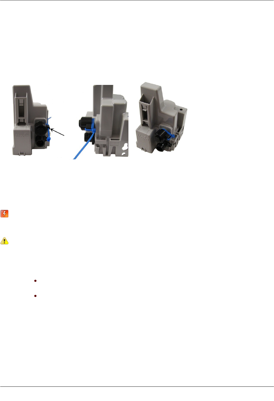
If 100W Endpoints with integral connectors (ERW-1300-X0X) and the registers are not installed at the same
time, secure the protective connector cover on the endpoint using a cable tie (Itron part number MSE-0005-
002). Cable ties are not shipped with the 100W Endpoint, but can be ordered from Itron. Use the protective
cover (on the endpoint side) in the field for up to one year.
Warning If a dual-port 100W Endpoint is installed but the Leak Sensor is not attached, the
environmental cap (MSC-0019-005) must remain in place on the blue connector (Leak Sensor
connector) to protect the connector from damage.
CH A P T E R 4
Installing the 100W and 100WP Endpoint
Installing the 100W and 100WP Endpoint
TDC-0909-001 100W and 100WP Pit Datalogging Water Endpoint Installation Guide 11
Proprietary and Confidential
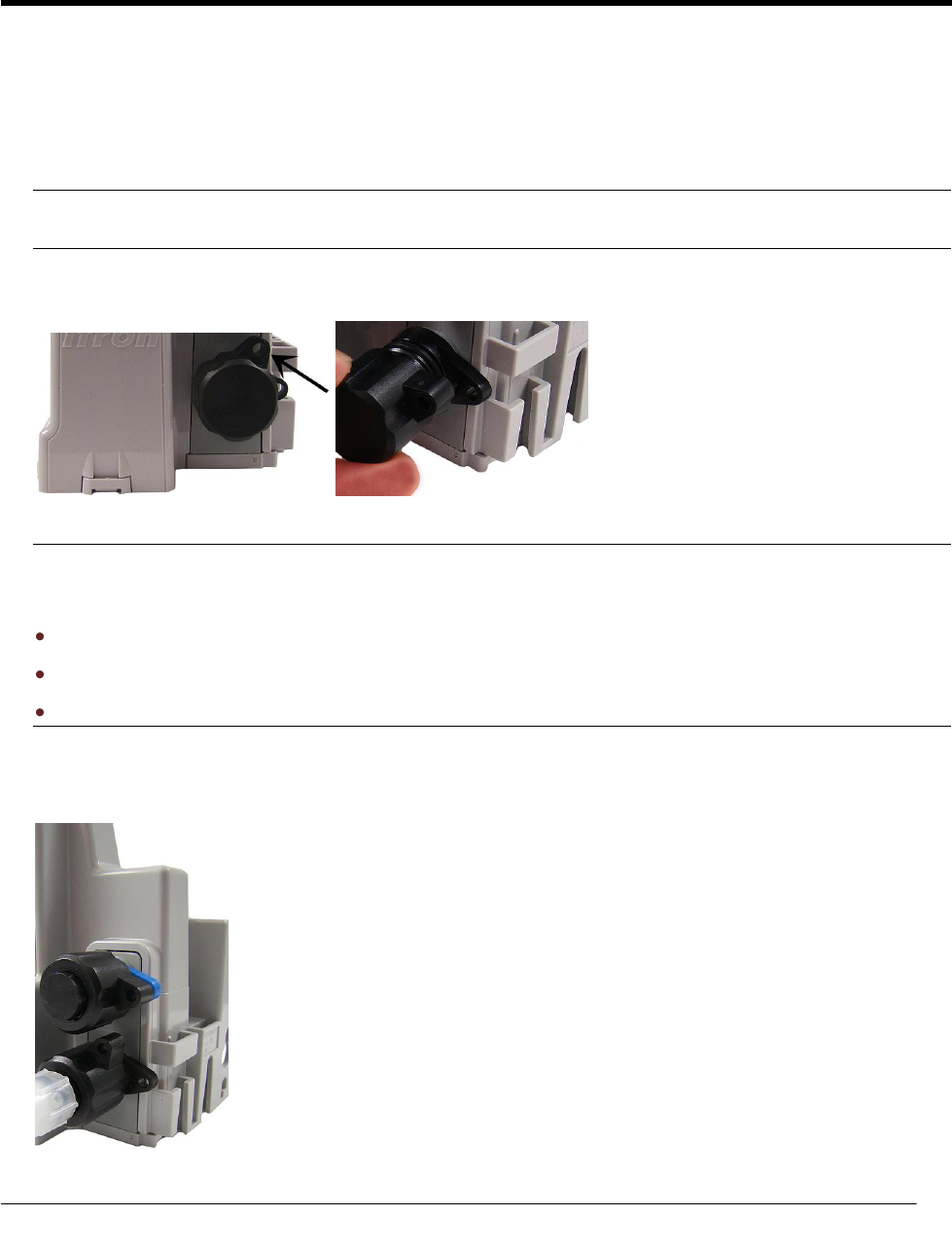
To install a cable tie to the connector
1. Thread the cable tie through the security holes in the connector and protective cover.
2. Thread the cable tie end through the eye of the cable tie.
3. Pull the cable tie tight to secure it (as shown).
4. Remove excess cable tie.
Rod Mount Installation
100W Endpoints can mount below the pit lid on a customer-supplied 1/2-inch OD rod. The example
installation described in this section uses a fiberglass rod. For more information, visit www.itron.com/
Products and Services and reference the Water Products Compatibility List.
Warning The rod installation area must be free from other pipes, wires, or facilities that may be
damaged by driving a rod into the ground.
Caution You must follow local codes when using the rod mount installation method. Failure to
use 1/2-inch rod and follow instructions may result in an unreliable installation.
Caution Observe the following guidelines for mounting the 100W or 100WP using the wall mount
procedure:
Endpoint positioning other than upright could negatively affect radio performance
and battery life.
Use only Itron-approved splice kits or inline connectors.
Installing the 100W and 100WP Endpoint
TDC-0909-001 100W and 100WP Pit Datalogging Water Endpoint Installation Guide 12
Proprietary and Confidential
Required Tools and Hardware
Hammer
1/2-inch outside diameter rod (either a square or round rod may be used)
Tape measure
Rod-driving tool (optional)
Cutting tool to adjust rod length
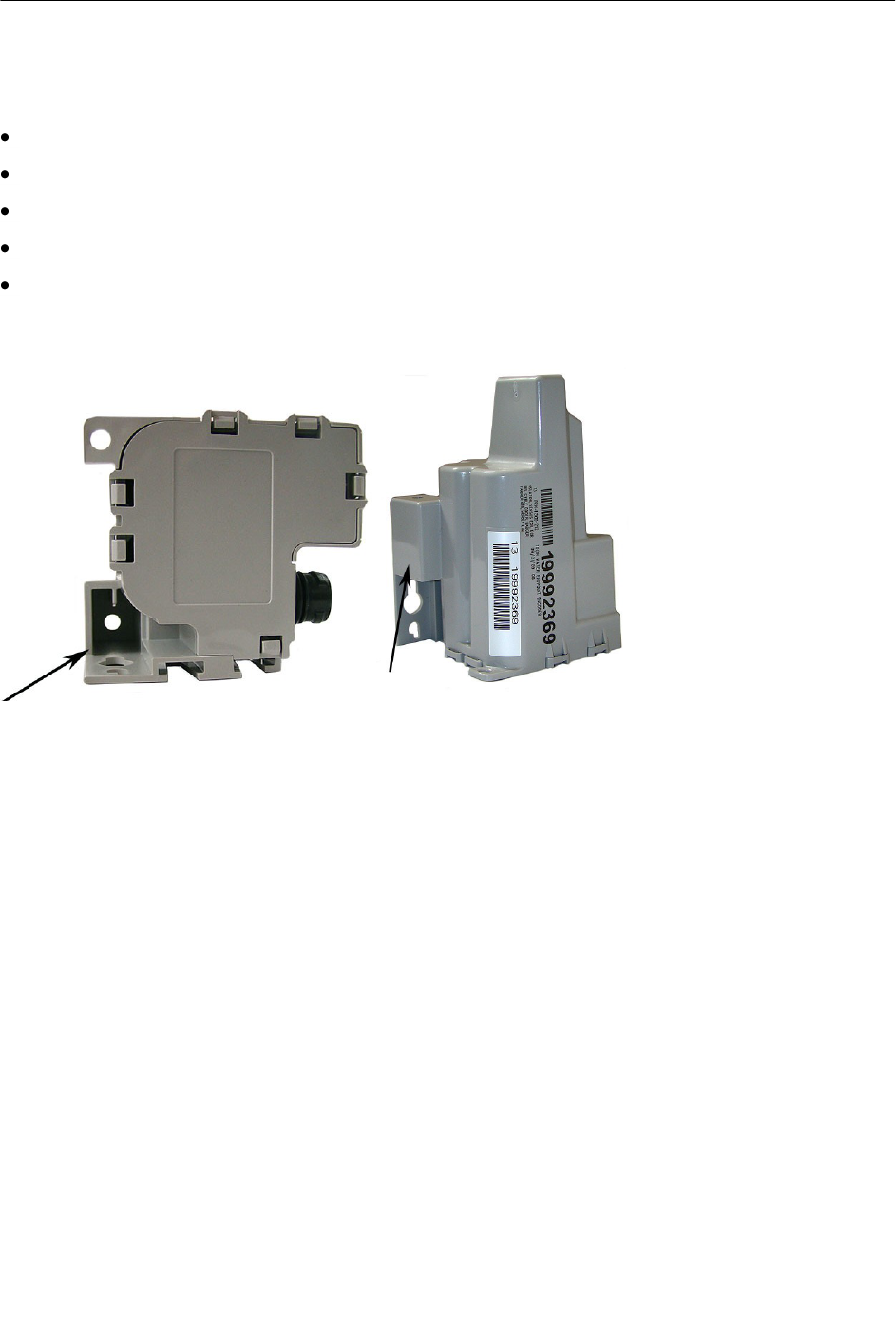
The 1/2-inch diameter rod hole is shown in the following bottom and side view of the 100W Endpoint.
To install the endpoint on a rod
1. Remove the pit lid. Inspect the area to make sure there are no buried cables, pipes, or other obstructions.
2. Measure the depth of the pit box from the top of the lip (where the lid will rest) to the bottom of the pit. Be
sure to measure the depth at the point where you will drive the rod into the ground.
3. Add 12 inches to the pit box depth measurement taken in step 2. The resulting total represents the
minimum length of rod needed. Soil types and moisture conditions may require longer rod lengths to
ensure the endpoint is well supported and remains vertical.
Installing the 100W and 100WP Endpoint
TDC-0909-001 100W and 100WP Pit Datalogging Water Endpoint Installation Guide 13
Proprietary and Confidential
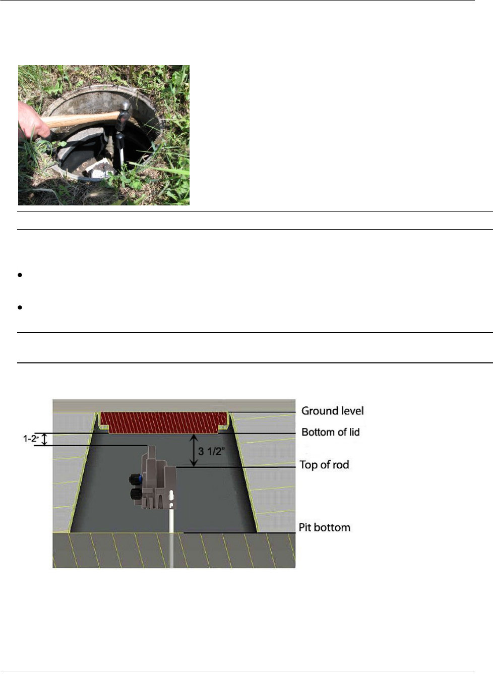
4. Without touching the meter body or adjacent pipes, position the rod as close to the center of the pit as
possible. Drive the rod into the ground. Ensure the rod remains vertical.
Note Rod shown has a protective end cap to protect the rod while driving it into the ground.
5. Drive the rod into the ground so the top of the rod is approximately 3-1/2-inches below the bottom of the
pit lid.
If the rod cannot be driven in enough to equal the necessary spacing, cut the remaining rod length to
the proper height using an abrasive cut off tool.
If the rod is driven to the correct depth but remains loose in the soil, replace the rod with a longer
version.
Caution Cutting fiberglass creates dust particles. Practice proper safety precautions when using cut-off
tools to prevent exposure to fiberglass dust particles.
Installing the 100W and 100WP Endpoint
TDC-0909-001 100W and 100WP Pit Datalogging Water Endpoint Installation Guide 14
Proprietary and Confidential
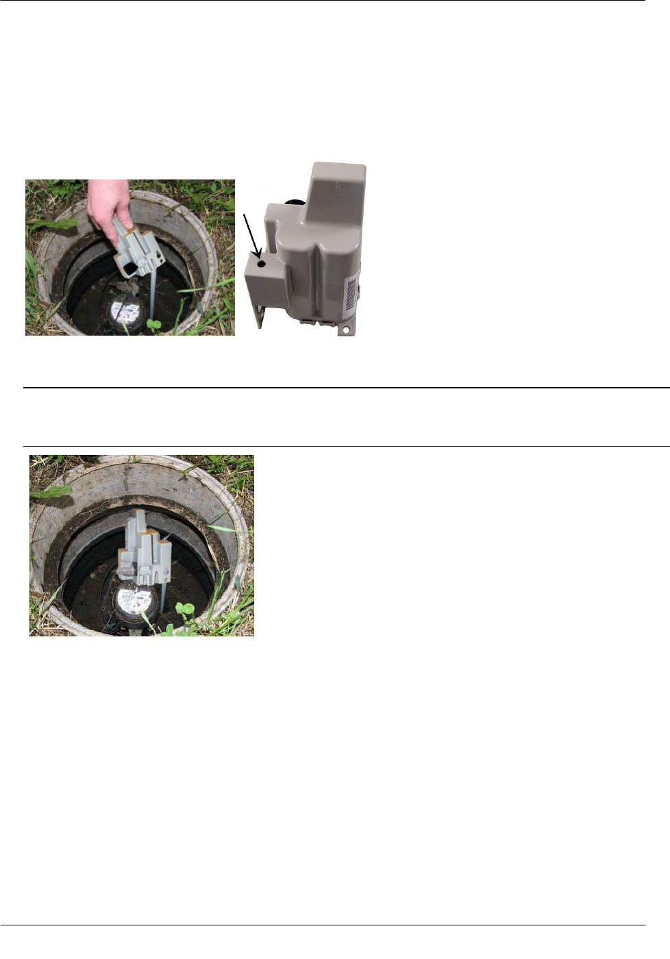
6. The top of the rod should be 3-1/2-inches below the bottom of the lid. Place the endpoint on the rod.
Completely insert the rod into the endpoint's rod mount hole. Do not force the endpoint onto the rod. If the
endpoint does not slide freely on the rod, remove the endpoint and examine the endpoint rod hole and rod
for burrs or obstructions. You may secure the endpoint to the rod with a self-drilling screw through the
hole in the top of the 100W rod mount cavity. The screw mounting hole is shown in the following product
image.
7. Installation is complete when the endpoint is perpendicular to the underside of the lid. The endpoint must
not contact the pit structure or lid.
Caution Verify the pit lid does not come in contact with the endpoint when the lid is replaced. There
must be a 1- to 2-inch space between the top of the endpoint and the bottom of the pit lid. If the endpoint
is installed too high, too low, or is touching any of the surrounding surfaces, adjust as necessary.
Installing the 100W and 100WP Endpoint
TDC-0909-001 100W and 100WP Pit Datalogging Water Endpoint Installation Guide 15
Proprietary and Confidential
Wall Mount Installation
Select a flat vertical mounting surface. Install the endpoint in an upright position; locate the endpoint as high
as possible. To mount the endpoint to the wall in a water pit box, select a mounting location on the inside of
the pit box and try to maintain a distance of one to two inches from the bottom of the pit box lid.
Caution Observe the following guidelines for mounting the 100W using the wall mount procedure:
Endpoint positioning other than upright could negatively affect radio performance and
battery life.
Use only Itron-approved splice kits or inline connectors.
The 100W and 100WP endpoints are suitable for use with up to 300 feet of Itron approved cable.
Required Tools and Hardware
Itron 100W Shelf Mount Kit
To install the endpoint using the wall mount procedure
1. Select a vertical surface in the pit box or on a wall (for example, endpoints mounted in basements).
2. Position the endpoint vertically so the top of the endpoint is between one and two inches below the bottom
of the lid.
3. Mark the location of the top mounting hole.
4. Drill a pilot hole in the pit box wall. Follow the screw manufacturer's recommendation for the size of the
pilot hole.
5. For concrete-type pit boxes, it may be necessary to use a screw anchor. Choose an anchor appropriate for
a #10 pan head screw.
Caution Do not over-tighten the mounting screws. Over-tightening the mounting screws may break the
endpoint mounting tabs.
Installing the 100W and 100WP Endpoint
TDC-0909-001 100W and 100WP Pit Datalogging Water Endpoint Installation Guide 16
Proprietary and Confidential
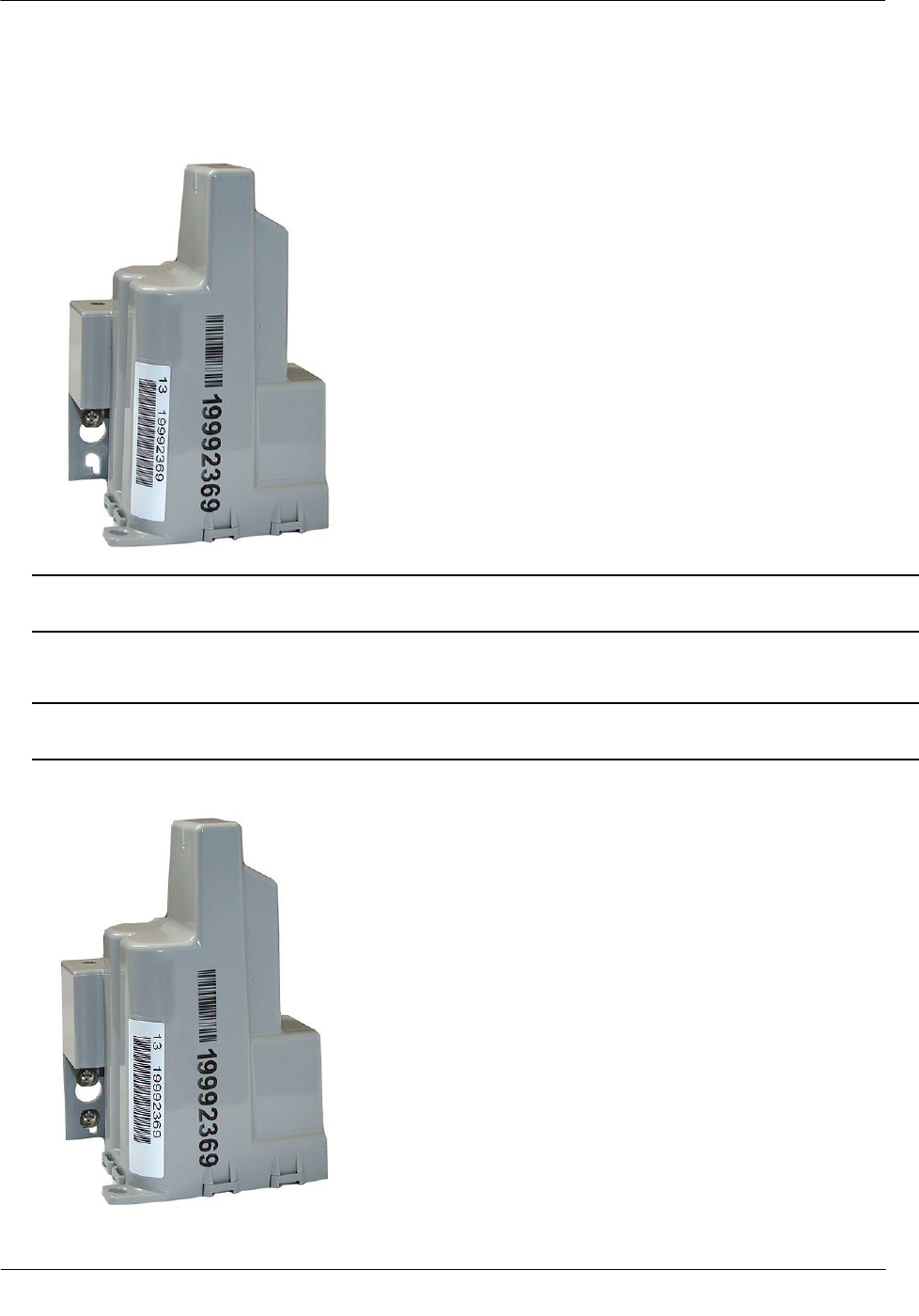
6. Start a screw into the pilot hole. Using the top hole of the endpoint, set the endpoint over the screw head
and slide it down so the screw is now at the top of the notch (as shown). Carefully tighten the screw until
snug. Over-tightening the mounting screw could crack the endpoint housing.
Note If mounting requires a screw anchor, mark the location of the bottom anchor and remove the
endpoint. Drill the required mounting hole, insert the anchor, and reattach the endpoint.
7. Holding the endpoint in the upright position, drill the second pilot hole. Use the bottom mounting hole as
a template.
Caution Any endpoint position other than upright may negatively affect radio performance and battery
life.
8. Screw the bottom screw into the pilot hole until snug. Do not over-tighten the mounting screw.
Installing the 100W and 100WP Endpoint
TDC-0909-001 100W and 100WP Pit Datalogging Water Endpoint Installation Guide 17
Proprietary and Confidential
Base Mount Installation
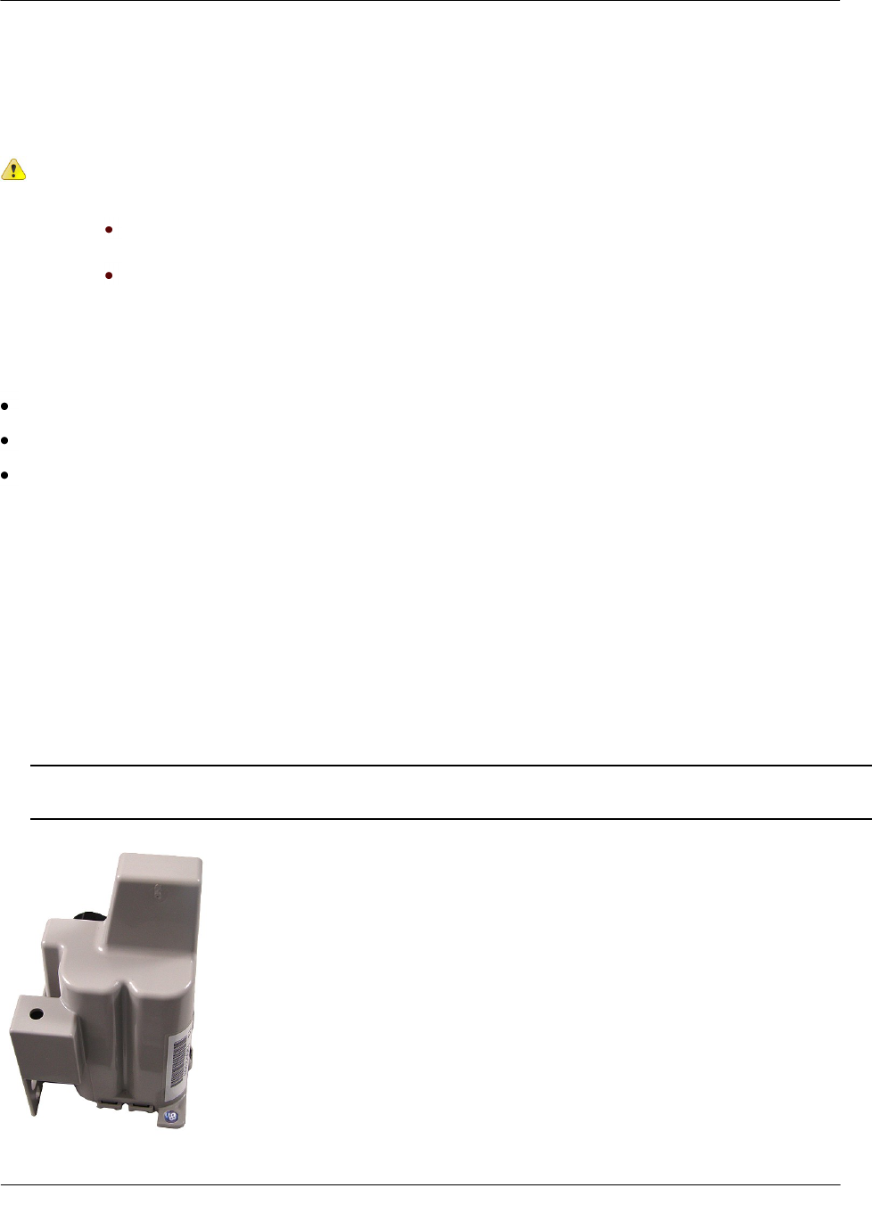
The endpoint may be mounted to a flat surface using the base tab.
Caution Observe the following guidelines for mounting the 100W using the wall mount
procedure:
Endpoint positioning other than upright could negatively affect radio performance
and battery life.
Use only Itron-approved splice kits or inline connectors.
Required Base Mounting Tools and Hardware
Drill and drill bits appropriate for mounting location material.
Common hand tools for the selected fastening method.
Mounting screws: #10 size pan head screws appropriate for the wall or pit box material.
To install the endpoint using the base mount procedure
1. Select a flat surface.
2. Position the endpoint vertically.
3. Mark the location of the mounting hole.
4. Drill a pilot hole in the mounting location material. Follow the screw manufacturer's recommendation for
the size of the pilot hole.
5. Position the 100W and insert a #10 pan head screw in the base mounting tab. Carefully tighten the
mounting screw until the 100W is secure.
Caution Do not over-tighten the mounting screws. Over-tightening the mounting screws may break the
endpoint mounting tabs.
Installing the 100W and 100WP Endpoint
TDC-0909-001 100W and 100WP Pit Datalogging Water Endpoint Installation Guide 18
Proprietary and Confidential
Shelf Mount Installation
This section describes endpoint installation using a shelf mount adapter to mount the endpoint in a pit lid slot.
Caution Observe the following guidelines for mounting the 100W using the wall mount
procedure:
Endpoint positioning other than upright could negatively affect radio
performance and battery life.
Use only Itron-approved splice kits or inline connectors.
The pit lid and slot must have the correct dimensions for the 100W or 100WP endpoint to fit
properly.
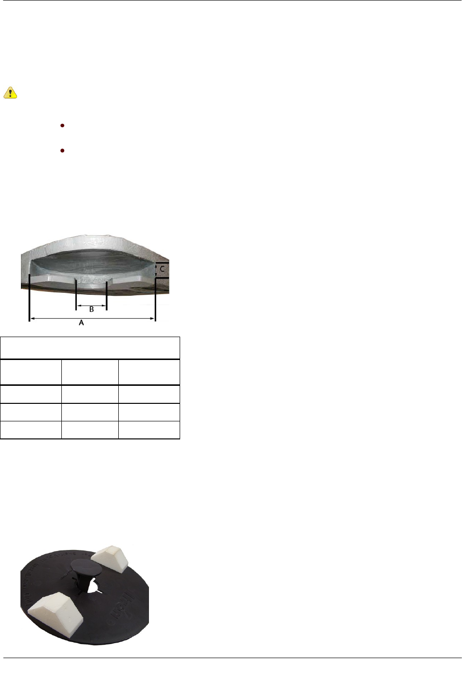
The following illustration and the accompanying table list the pit lid slot dimensions for the shelf mount
installation method.
Pit Lid Slot Dimensions
Dimension
Minimum
(inches)
Maximum
(inches)
A
6 3/4
N/A
B
2
5 3/4
C
3/4
1
Required Tools and Hardware
Itron 100W Shelf Mount Kit
To install using the shelf mount adapter
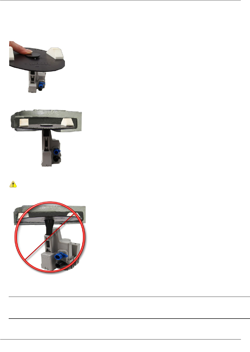
1. With the foam spacers facing up, insert the shelf mount adapter into the opening in the disk.
Installing the 100W and 100WP Endpoint
TDC-0909-001 100W and 100WP Pit Datalogging Water Endpoint Installation Guide 19
Proprietary and Confidential
2. Push the adapter into the opening gently until the adapter snaps into place. Insert the shelf mount adapter
into the 100W Endpoint antenna slot pushing firmly with your thumb until the adapter tab locks into place
in the opening of the 100W antenna slot.
3. Slide the adapter assembly into the pit lid with the foam spacers positioned on each side of the pit lid slot.
Correct position for foam spacers
Caution Do not install the adapter assembly in a manner that provides little or no support
under disk's edge.
Incorrect mounting position for foam spacers
4. The installed position of the endpoint should be vertical and upright when the lid is replaced on the pit.
Caution When placing the pit lid on to the pit box after shelf mount adapter installation, use care to avoid
pinching or damaging the endpoint to meter cable. Any endpoint position other than upright may
negatively affect radio performance and battery life.

Installing the 100W and 100WP Endpoint
TDC-0909-001 100W and 100WP Pit Datalogging Water Endpoint Installation Guide 20
Proprietary and Confidential
Through Lid Mount
This section provides instructions to mount the 100W Endpoint in a pit lid with a drilled, round 1-3/4-inch, 1
7/8-inch, or 2-inch hole.
Caution Some pit lids have a molded, recessed cavity that allows Itron 40W-1, 50W-1, and 50W-2
ERT modules to sit flush with the top surface of the lid. However, the dome of the endpoint retainer
for the 100W and 100WP endpoints has a smaller diameter and does not fill the pit lid cavity. This
can cause the cavity to become a trip hazard. Itron does not recommend using this type of pit lid
with 100W endpoints.
Required Tools and Hardware
This mounting method requires the Pit Lid Mounting Kit. Refer to the 100W Installation Methods Overview
(PUB-1300-004) for guidance on which kit to install for different pit lid material and traffic conditions.
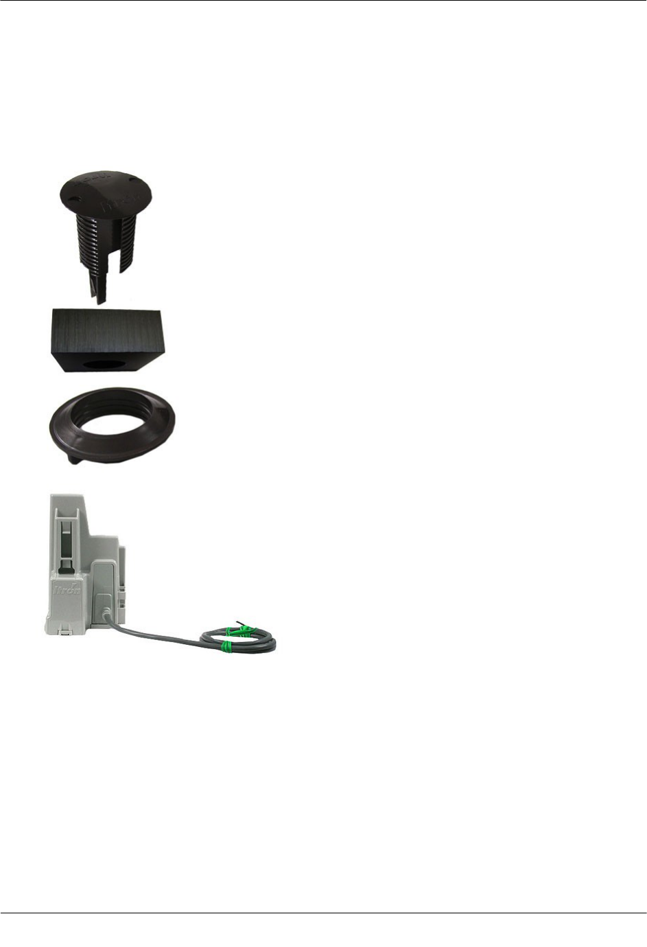
Pit Lid Mounting Kit (CFG-1300-004)
Note The Pit Lid Mounting Kit is not intended for applications involving vehicular traffic. Use the
Remote Antenna Kit in incidental traffic areas (such as residential environments).
Installing the 100W and 100WP Endpoint
TDC-0909-001 100W and 100WP Pit Datalogging Water Endpoint Installation Guide 21
Proprietary and Confidential
To install in lids with holes using the Pit Lid Mounting Kit (CFG-1300-004)
This section provides the instructions to install the 100W Endpoint in a pit lid with a hole using the Pit Lid
Mounting Kit (CFG-1300-004).
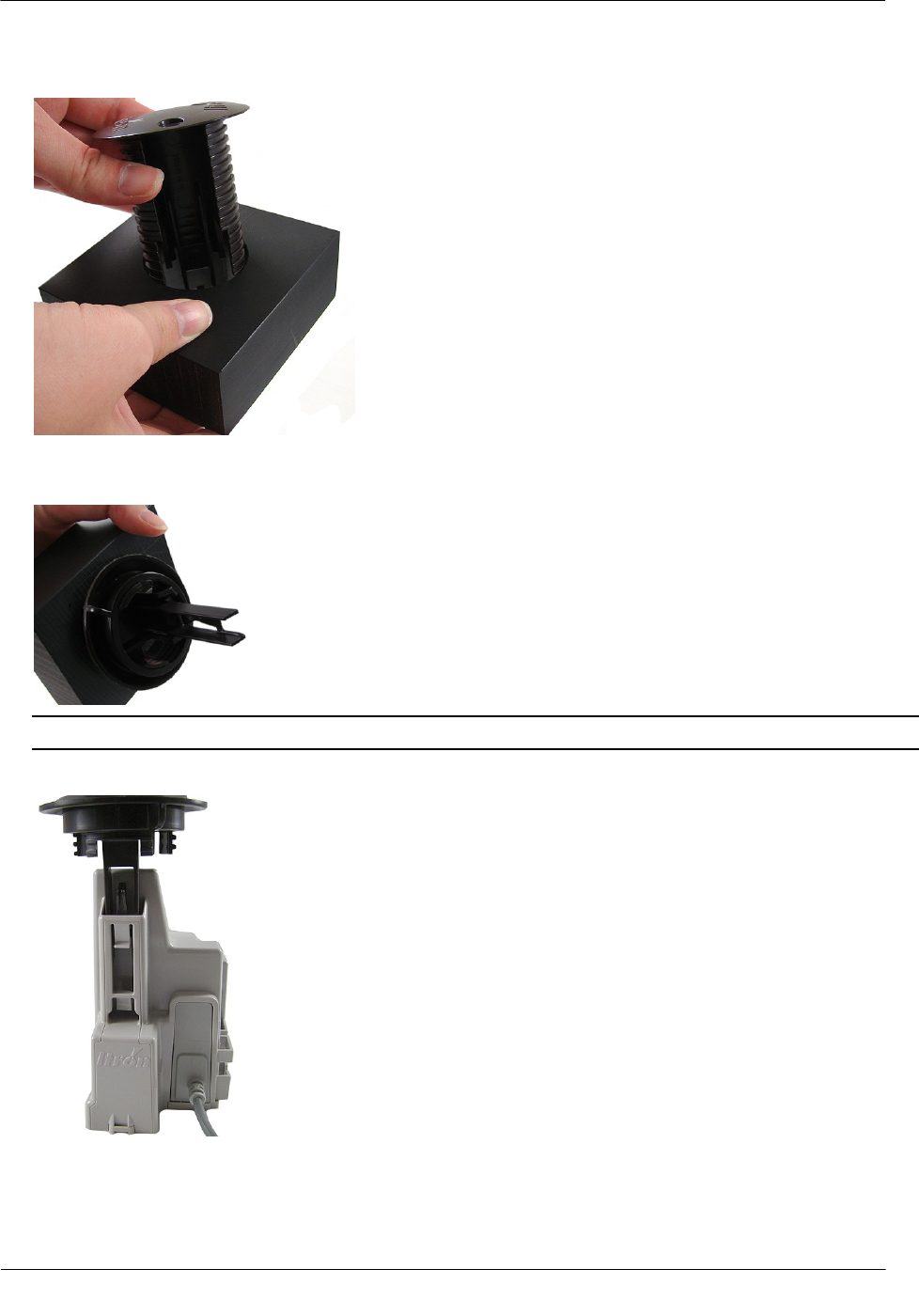
1. Verify you have the following items to complete the installation.
A
Retainer clip
B
Pit lid with a pre-drilled hole
(simulated pit lid material shown)
C
Retainer clip collar
D
100W/100WP endpoint
A
B
C
D
Installing the 100W and 100WP Endpoint
TDC-0909-001 100W and 100WP Pit Datalogging Water Endpoint Installation Guide 22
Proprietary and Confidential
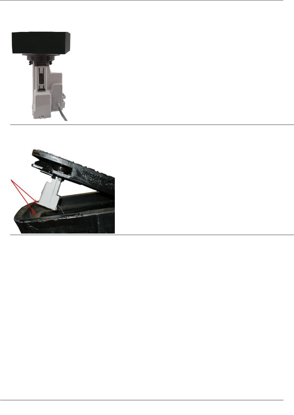
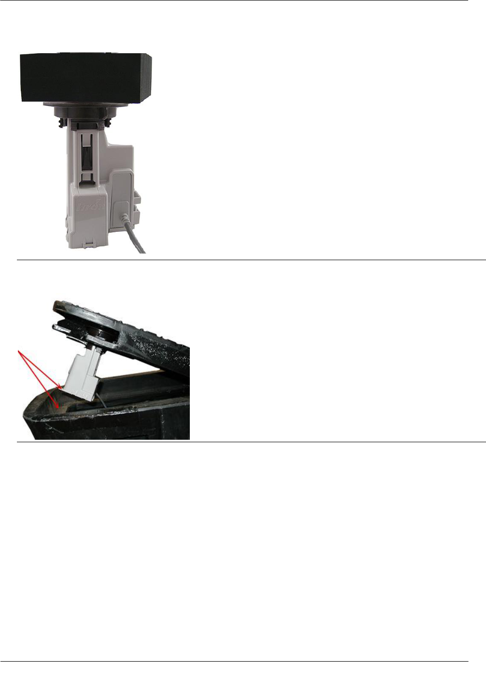
2. Insert the retainer clip into the hole in the pit lid with the convex surface on the top of the pit lid.
3. From the bottom side of the lid, screw on the threaded retainer clip collar until the beveled top rests
against the pit lid.
Note Ensure the beveled edge is toward the top of the lid.
4. Align and insert the retainer clip tab into the retainer clip receptacle on the 100W housing.
Installing the 100W and 100WP Endpoint
TDC-0909-001 100W and 100WP Pit Datalogging Water Endpoint Installation Guide 23
Proprietary and Confidential
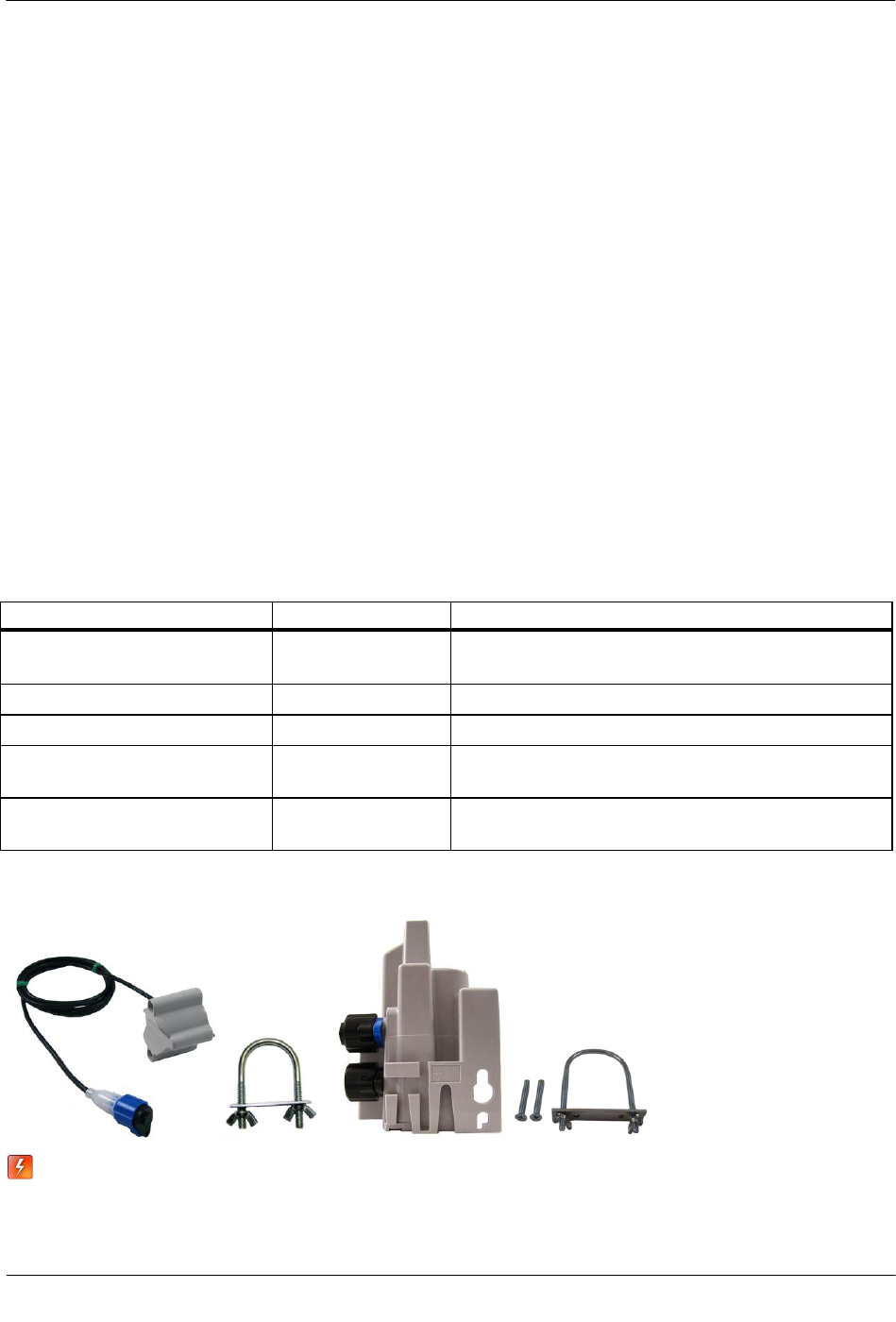
5. Verify the clip locks into place in the housing.
Caution Carefully align the 100W through lid assembly. If the assembly is improperly aligned, the pit lid
may not close.
Pit Lid Mounting Kit installation is complete.
Installing in a New Lid
This section describes installation of the endpoint in a pit lid without a drilled hole.
To install the 100W in new lids
1. Select a hole location with enough clearance on the bottom side of the lid to attach the threaded clip collar.
2. Drill a 1-3/4-inch hole in the lid.
3. See To install in lids with holes using the Pit Lid Mounting Kit to complete installation in a new lid.
Installing the 100W and 100WP Endpoint
TDC-0909-001 100W and 100WP Pit Datalogging Water Endpoint Installation Guide 24
Proprietary and Confidential
Optional Leak Sensor Installation
Leak Sensors (LS) analyze water flow sound patterns to detect new, evolving, and pre-existing leaks. LS
analysis data is uploaded to mlogonline™ Network Leak Monitoring for data analysis accessed through a
secure Internet portal unique to your utility. This section describes installation of the Leak Sensor (LS) in a
100W or 100WP system.
The 100W endpoint stores 20 days of Leak Sensor data. On the 21st day, the 100W begins to write over stored
data in a first in, first out manner.
The 100W automatically detects the presence of connected Leak Sensors. The 100W will automatically detect
the Leak Sensor within 22.5 minutes and begin reading leak sensor data. To immediately detect the Leak
Sensor and begin reading data, perform a Check ERT with a handheld computer running FDM software.
The LS is used in conjunction with both indoor (basement) and outdoor (mounting on the exterior of the
house) endpoint. LS devices mount on a water service pipe or meter insetter (meter horn) and connect to the
appropriate endpoint wires as described in Connecting the Leak Sensor to the endpoint. The mounting bracket
shipped with the Leak Sensor accommodates an (up to) 1-1/2-inch OD pipe. An optional mounting bracket is
available for pipe sizes (up to 2 1/2-inch OD).
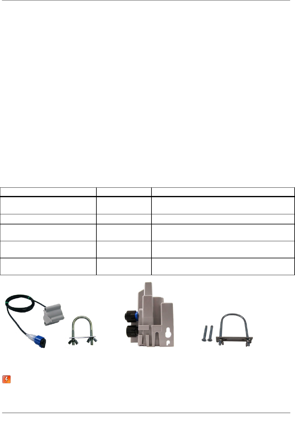
Required Equipment
Equipment
Itron Part Number
Description
Leak Detection Sensor
LDS-0001-002
LDS with inline connector, environmental connector cap; 5-foot
cable, and mounting bolt (fits up to 1 1/2-inch OD pipe).
Optional mounting bracket
CFG-0349-002
Mounting bolt fits up to 2 1/2-inch OD pipe.
100W Endpoint
ERW-1300-002
Dual port 100W or 100WP for LS and environmental connector
caps.
25-foot extension cable
CFG-0349-101
25-foot cable with coordinating connectors (LS blue connector,
register black connector).
100W LS environmental replacement cap
MSC-0019-005
Protects Leak Sensor connector when the Leak Sensor is not
connected to the endpoint.
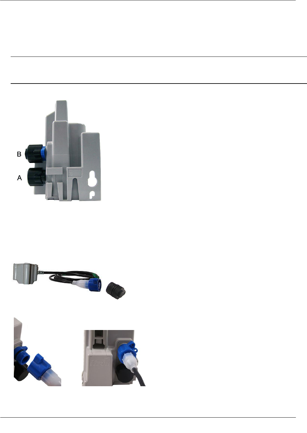
Leak Sensor Standard mounting 100W/100WP endpoint Optional mounting
bracket bracket
Warning When the 100W or 100WP endpoint is installed but the Leak Sensor is not
attached, the blue Leak Sensor port must be protected with the environmental cap (MSC-
0019-005). If the Leak Sensor is removed from the endpoint, the environmental cap must be
replaced to protect the connector.
Installing the 100W and 100WP Endpoint
TDC-0909-001 100W and 100WP Pit Datalogging Water Endpoint Installation Guide 25
Proprietary and Confidential
To connect the Leak Sensor to the endpoint
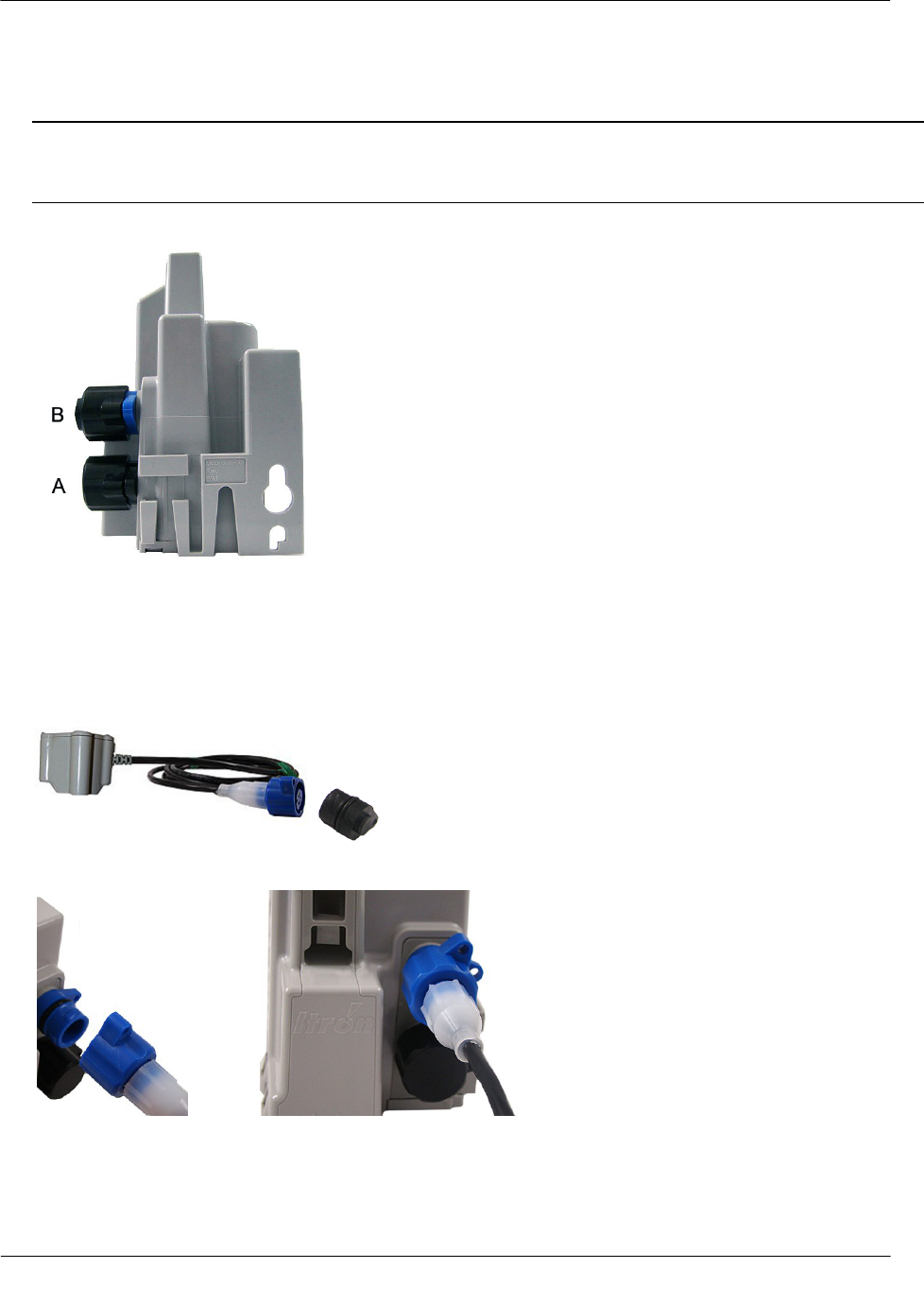
Caution Verify you have the correct 100W or 100WP endpoint. Leak Sensors must mount to Port B (top
port) of the endpoint. Connecting the LS to Port A (bottom port) will cause electrical damage to the LS
and endpoint.
1. Remove the environmental cap from the 100W endpoint blue connector (B).
B. 100W blue connector: Leak Sensor connection
A. 100W black connector: Register connection
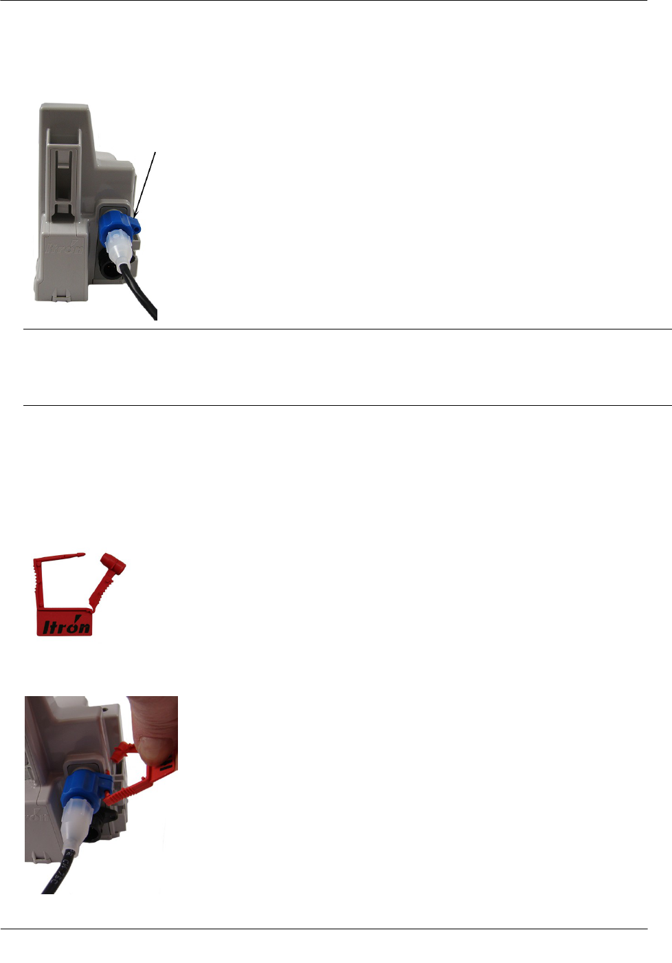
2. Remove the environmental cap from the Leak Sensor connector. Verify the connectors (100W LS
connector and the Leak Sensor connector) are clean and dry.
3. Align the Leak Sensor connector with the endpoint's blue connector and insert.
Installing the 100W and 100WP Endpoint
TDC-0909-001 100W and 100WP Pit Datalogging Water Endpoint Installation Guide 26
Proprietary and Confidential
4. Rotate the connector locking ring until the security holes align.
Caution Do not force the connector ends together. While holding the LS connector, engage the endpoint
connector by rotating the locking ring until both connectors securely connect. Twist only the connector
locking ring, not the body of the connector. Twisting the connector body could damage the connector's
pins.
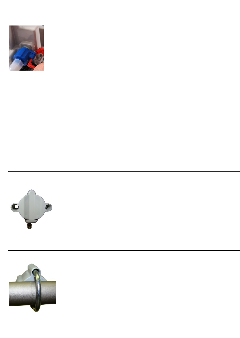
To attach an Itron Security Seal through the connector security hole
Required Materials
Itron Security Seal (MSC-0018-001)
1. Insert the pointed end of the security seal through the inline connector and the 100W connector security
holes.
Installing the 100W and 100WP Endpoint
TDC-0909-001 100W and 100WP Pit Datalogging Water Endpoint Installation Guide 27
Proprietary and Confidential
2. Insert the pointed end of the security seal into the capped end and push until the seal locks.
This completes 100W or 100WP endpoint and Leak Sensor connections.
Pipe Preparation
Clean any dust or dirt from the pipe to facilitate direct contact with the LS surface.
To install the Leak Sensor on a pipe or meter insetter
1. Select a Leak Sensor mounting location within 5 feet of the endpoint. Mount the sensor on the water input
side of the meter.
Caution The Leak Sensor must be mounted on the water input side of the meter. Failure to follow this
mounting requirement could result in errors in the leak detection data. Installation requires Itron mounting
hardware. Repair costs and service charges relating to the use on non-compliant mounting hardware will
be charged to the customer. Contract Itron Support for more information.
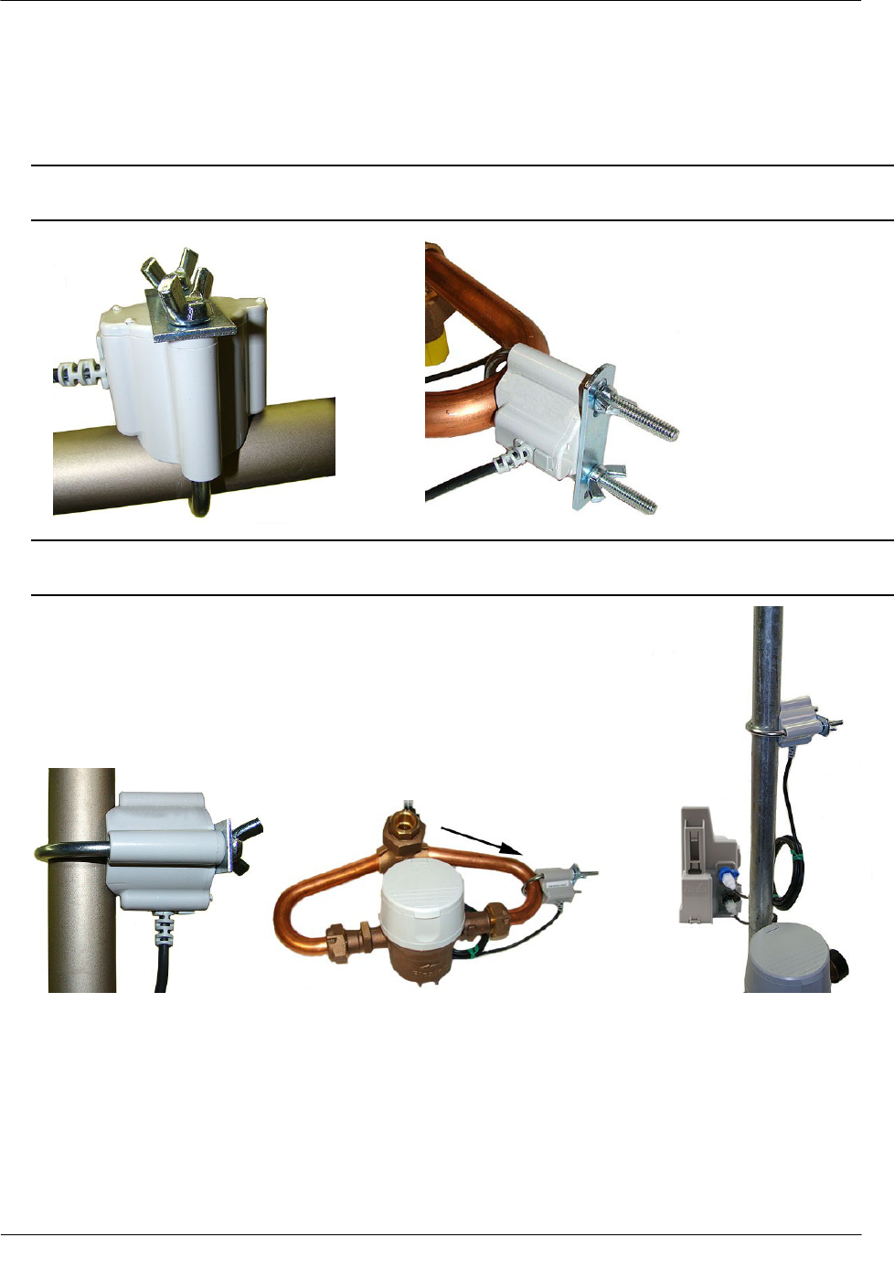
2. Verify the pipe’s mounting surface is free from dirt and debris. Place the curved surface of the LS against
the pipe.
3. Insert the mounting U-bolt over the pipe and into the LS mounting holes.
Caution Do not mount the Leak Sensor on a pipe coupler, joint, or nut.
Installing the 100W and 100WP Endpoint
TDC-0909-001 100W and 100WP Pit Datalogging Water Endpoint Installation Guide 28
Proprietary and Confidential
4. Insert the mounting plate over the U-bolt's threaded screw ends. Attach the two wing nuts over the clamp
screw ends and tighten the wing nuts until snug (to a minimum of 5-inch pounds) to prevent device
rotation on the pipe. After the second wing nut is tightened, check the Leak Sensor to verify the device is
snug. If the sensor moves, tighten the wing nuts until there is no movement.
Caution Do not tighten the Leak Sensor to more than 20 inch-pounds. Over-tightening could damage the
Leak Sensor housing and/or the pipe.
Note Leak Sensor mounting orientation is not critical. Orient the Sensor to best accommodate your
installation. The most important installation practice is to mount the Sensor securely to the pipe.
Installing the 100W and 100WP Endpoint
TDC-0909-001 100W and 100WP Pit Datalogging Water Endpoint Installation Guide 29
Proprietary and Confidential
To install the Leak Sensor on a pipe (up to 2 1/2-inch OD)
1. Select a Leak Sensor mounting location within 5 feet of the 100W endpoint.
Note Leak Sensor mounting orientation is not critical. Orient the Sensor to best accommodate your
installation. The most important installation practice is to fasten the Sensor securely to the pipe.
Caution The Leak Sensor must be mounted on the water input side of the meter. Failure to follow this
mounting requirement could result in errors in the leak detection data. Installation requires Itron mounting
hardware. Repair costs and service charges relating to the use on non-compliant mounting hardware will
be charged to the customer. Contract Itron Support for more information.
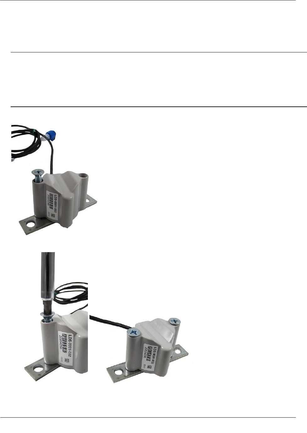
2. Insert the mounting plate screws into the holes on the Leak Sensor's curved surface.
3. Secure the mounting plate to the Leak Sensor.
Installing the 100W and 100WP Endpoint
TDC-0909-001 100W and 100WP Pit Datalogging Water Endpoint Installation Guide 30
Proprietary and Confidential
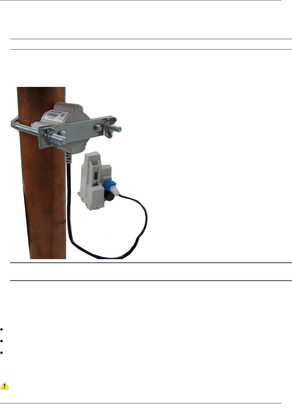
4. Verify the pipe’s mounting surface is free from dirt and debris. Place the curved surface of the LS against
the pipe.
Caution Do not mount the Leak Sensor on a pipe coupler, joint, or nut.
5. Insert the U-bolt around the pipe and into the holes in the plate/Leak Sensor assembly. Secure the U-bolt
with the wing nuts. Tighten the wing nuts until snug (to a minimum of 5-inch pounds) to prevent device
rotation on the pipe. After you tighten the second wing nut, check the Leak Sensor to verify the device is
snug. If the sensor moves, tighten the wing nuts until there is no movement.
Caution Do not tighten the Leak Sensor to more than 20 inch-pounds. Over-tightening could damage the
Leak Sensor housing and the pipe.
Optional Remote Antenna Installation
The optional 900 MHz remote mount antenna provides increased RF range coverage for the listed mobile
applications:
Meters located deep in a pit boxes.
Meters submerged in water for extended time periods.
Meters in Fixed Network systems.
This section provides antenna mounting instructions through a pit lid and the instructions to connect the
antenna to the 100W.
Caution Optional remote antenna installation applies only to mobile applications.
Installing the 100W and 100WP Endpoint
TDC-0909-001 100W and 100WP Pit Datalogging Water Endpoint Installation Guide 31
Proprietary and Confidential
Mounting the Remote Antenna
Metal lids on water pit boxes require a through-lid solution for optimal endpoint radio performance. The
remote antenna is designed to fit in a pit lid hole with a diameter between 1 3/4-inch to 2-inches and lid
thicknesses from 1/4-inch to 1 3/4-inch.
To mount the optional remote antenna through a pit lid
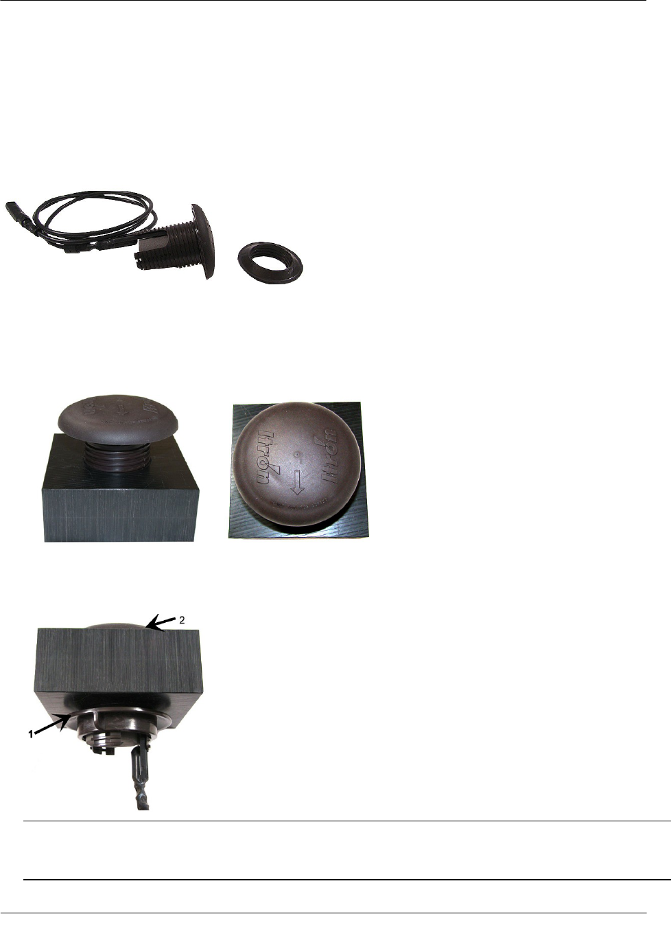
1. Insert the remote antenna into the hole in the pit lid with the convex surface on the top of the pit lid.
(These instructions show a simulated pit lid material.)
2. From the bottom side of the lid, screw on the threaded collar two or three turns. Turn the threaded collar
until it is tight against bottom of the pit lid. Verify the antenna dome does not move up and down or shift
laterally.
Note Ensure the beveled edge (1) of the threaded collar is toward the top of the lid (2). The Itron-
recommended placement centers the remote antenna and takes up the extra space in mounting holes up to
2 1/2-inches.
Installing the 100W and 100WP Endpoint
TDC-0909-001 100W and 100WP Pit Datalogging Water Endpoint Installation Guide 32
Proprietary and Confidential
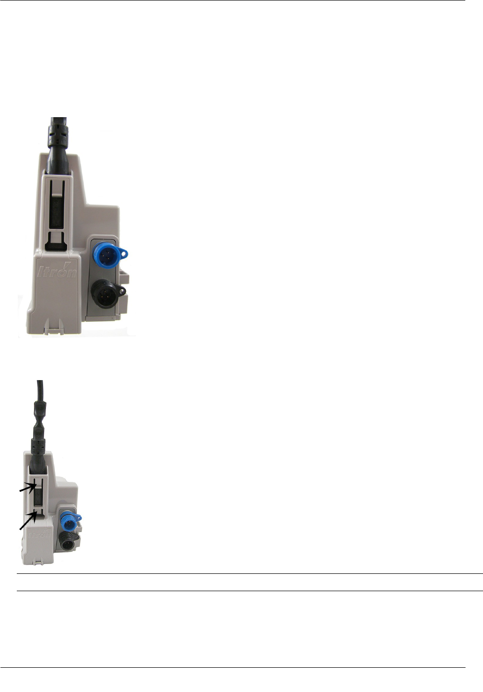
To connect the remote antenna coupler to the endpoint
1. Insert the remote antenna cable coupler into the endpoint’s antenna slot with the flat side of the coupler
against the endpoint housing.
2. Push the antenna coupler into the antenna slot until the coupler locks into the tabs of the antenna slot.
Important Verify the antenna coupler locks with the antenna slot's tabs.
Remote antenna installation is complete.
TDC-0909-001 100W and 100WP Pit Datalogging Water Endpoint Installation Guide 33
Proprietary and Confidential
This section describes the 100W and 100WP connections to the water meter register using the inline
connector assembly. Follow the manufacturer's recommended procedure for installing the water meter register
on the meter.
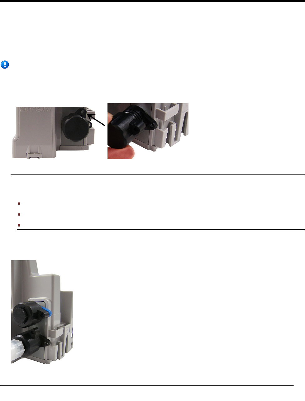
To connect the inline connector
Note If an inline connector is not used and the endpoint is already connected to the water meter
register, skip this step.
1. Remove the protective cover from the connector by twisting the two halves in opposite directions. Pull the
halves apart.
Caution Verify the connector halves are clean and dry before assembly.
If any of the following conditions occur, do not install the endpoint:
Any of the three pins are damaged or missing.
The O-ring is missing.
The cable is cut or nicked
2. Connect the register cable to the endpoint connector. Holding the connectors by the back shells, rotate one
end to align the keyed slots. Push until snug. Slide the black coupling nut over the O-ring. Make sure the
O-ring stays seated. If the O-ring does not stay seated, disconnect and try again.
AP P E N D I X A
Using an Inline Connector
Using an Inline Connector
TDC-0909-001 100W and 100WP Pit Datalogging Water Endpoint Installation Guide 34
Proprietary and Confidential
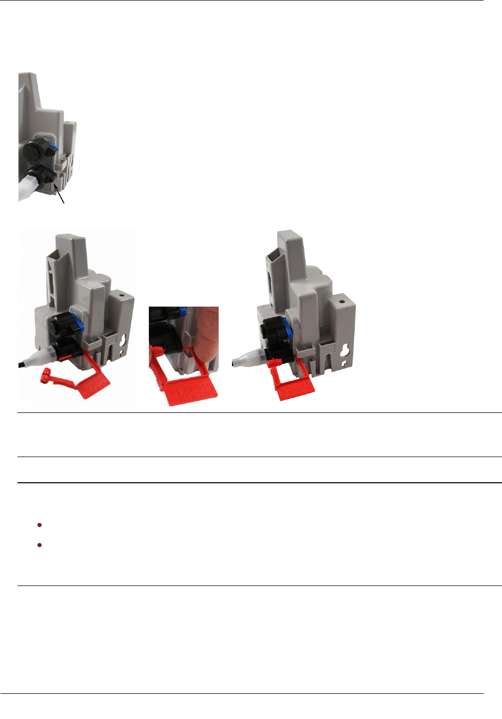
3. Twist the register cable's black coupling nut to align the two tabs.
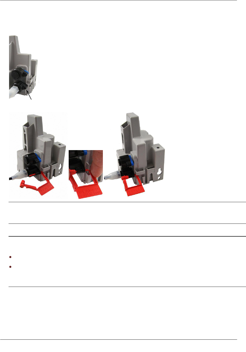
4. Install the security seal as shown. Push it until it snaps into place.
Note For future meter or endpoint servicing, break the security seal by pulling apart. The original
protective connector covers are reusable if they are kept clean and dry. Install a new security seal after
servicing either device. To order more parts, see the Water Endpoint Ordering Guide (PUB-0063-001).
Caution Shield connectors with protective environmental covers. Do not leave an exposed connector in
the field.
Leak Sensor connector environmental cover: MSC-0019-005
Register connector environmental cover: MSC-0019-001, 1-year life.
The Leak Sensor environmental Cap employs multiple seals to increase cap life. The Leak Sensor's cap
design allows utilities to install the endpoint and install the Leak Sensor at a later date.
TDC-0909-001 100W and 100WP Pit Datalogging Water Endpoint Installation Guide 35
Proprietary and Confidential
This section describes connecting the 100W or 100WP endpoint to the water meter register using gel cap
connectors.
Required Materials
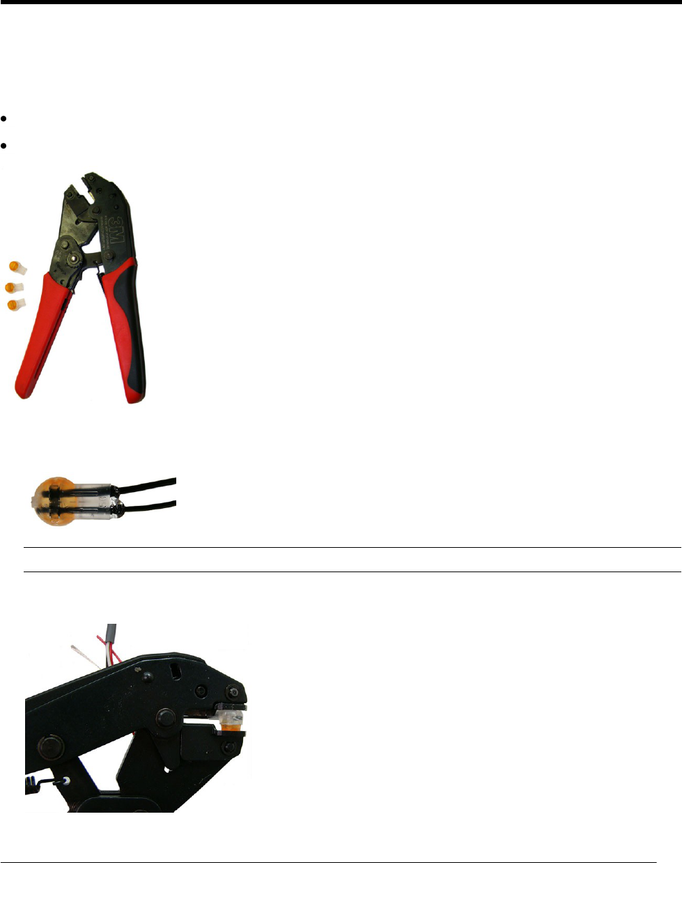
E-9R 3M® gel cap crimping tool
Itron Splice Kit (OEM-0034-002)
1. Push two wires as far as possible into the connector.
Caution Do not strip insulation from the ends of the wires before inserting them into the connector.
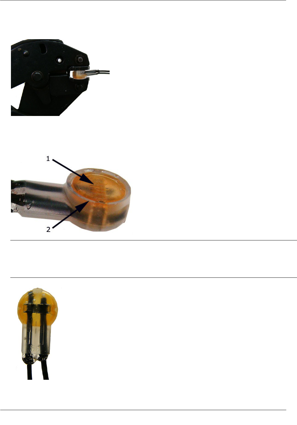
2. Carefully place the connector and wires into the jaws of the crimping tool. Make sure the wires remain
fully inserted in the gel-cap connector.
AP P E N D I X B
Using Gel Cap Connectors
Using Gel Cap Connectors
TDC-0909-001 100W and 100WP Pit Datalogging Water Endpoint Installation Guide 36
Proprietary and Confidential
3. Crimp the connector by squeezing the handles until the connector cap is fully seated. Continue to apply
pressure for three seconds.
4. A connector is crimped properly when the top of the movable yellow center (1) is flush with the top of the
connector body (2).
Warning Crimping the connector forces some sealant out of connector. The sealant protects the inside of
the connector against insects, moisture, and other contaminants.
The sealant may cause minor eye and skin irritation. Avoid eye contact. Avoid prolonged or repeated skin
contact. Contact Itron Support for Material Safety Data Sheets (MSDS).
Using Gel Cap Connectors
TDC-0909-001 100W and 100WP Pit Datalogging Water Endpoint Installation Guide 37
Proprietary and Confidential
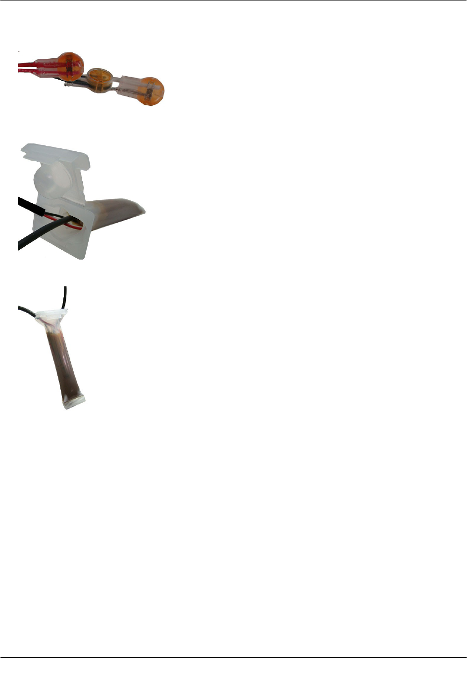
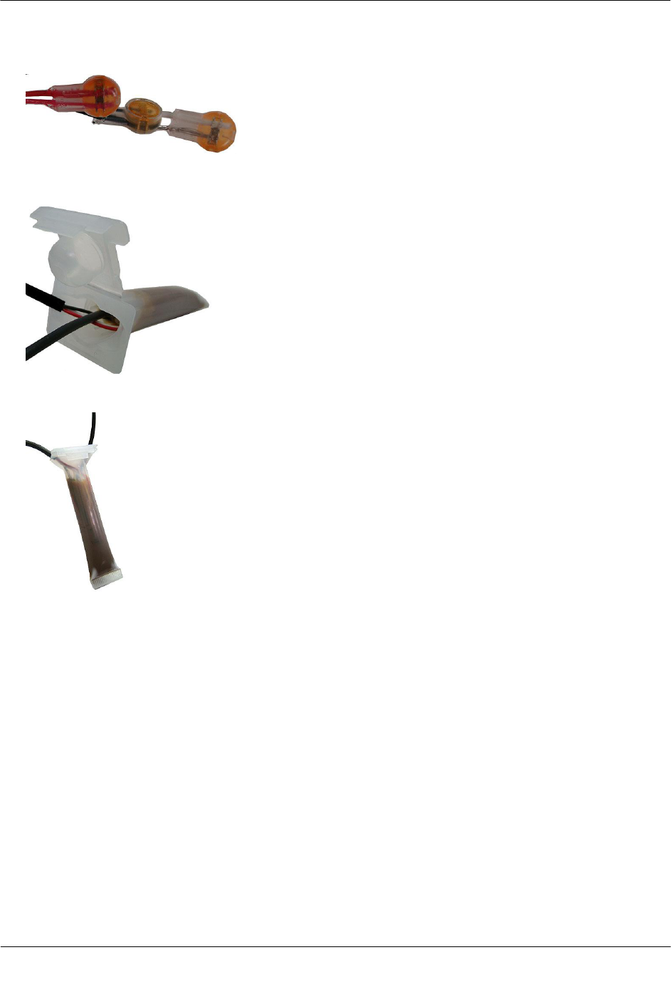
5. After you complete all endpoint to register wire connections, arrange the connectors in a single file.
6. Insert the connectors and wires into the splice tube until the connectors and wires completely immerse in
the splice tube's gel material.
7. Separate the cables to the sides and close the splice tube cover.
8. Discard any leftover materials from the customer premises.

TDC-0909-001 100W and 100WP Pit Datalogging Water Endpoint Installation Guide 38
Proprietary and Confidential
AP P E N D I X C
Troubleshooting

TDC-0909-001 100W and 100WP Pit Datalogging Water Endpoint Installation Guide 39
Proprietary and Confidential
Symbols & Numbers
100W and 100WP Models • 4
100W and 100WP Transmission Modes • 4
100W and 100WP Endpoint Accessories • 10
100W and 100WP Endpoints with Integral
Connectors • 10
100W Operating Modes • 5
100WP Operating Modes • 5
A
About the 100W and 100WP Endpoint • 3
B
Base Mount Installation • 17
Battery Life • 4
Before You Begin • 1
C
Connecting the 100WP to a Remote Meter
Register • 9
Connecting to a Meter Register Using a Cable • 7
Connecting to a Meter Register Using the Inline
Connector • 7
Connecting, Initializing, and Programming • 7
H
How This Document is Organized • 2
I
Initializing the 100W • 7
Installing and Connecting • 7
Installing in a New Lid • 23
Installing the 100W and 100WP Endpoint • 10
M
Mounting the Remote Antenna • 31
O
Optional Leak Sensor Installation • 24
Optional Remote Antenna Installation • 30
P
Pipe Preparation • 27
R
Related Documents • 2
Required Base Mounting Tools and Hardware • 17
Required Equipment • 24
Required Tools and Hardware • 12, 15, 18, 20
Rod Mount Installation • 11
S
Shelf Mount Installation • 18
T
Through Lid mount • 20
To connect the 100W to the register • 8
To connect the inline connector • 33
To connect the Leak Sensor to the 100W Endpoint
• 25
To connect the remote antenna coupler to the
100W Endpoint • 32
To install a cable tie to the connector • 11
To install in lids with holes using the Pit Lid
Mounting Kit (CFG-0771-011) • 21
To install the 100W Endpoint on a rod • 12
To install the 100W Endpoint using the base
mount procedure • 17
To install the 100W Endpoint using the wall
mount procedure • 15
To install the 100W in new lids • 23
To install the Leak Sensor on a pipe (up to 2 1/2-
inch OD) • 29
To install the Leak Sensor on a pipe or meter
insetter • 27
To install using the shelf mount adapter • 18
Troubleshooting • 38
U
Using an Extension Cable • 9
Using an Inline Connector • 33
Using Gel-cap Connectors • 35
V
Verifying Operation of the 100W and 100WP
Endpoint • 9
W
Wall Mount Installation • 15
Index
Users Manual .2
Installing the 100W Endpoint
TDC-0909-002 100W and 100WP Pit Datalogging Water Endpoint Installation Guide 17
Proprietary and Confidential
Base Mount Installation
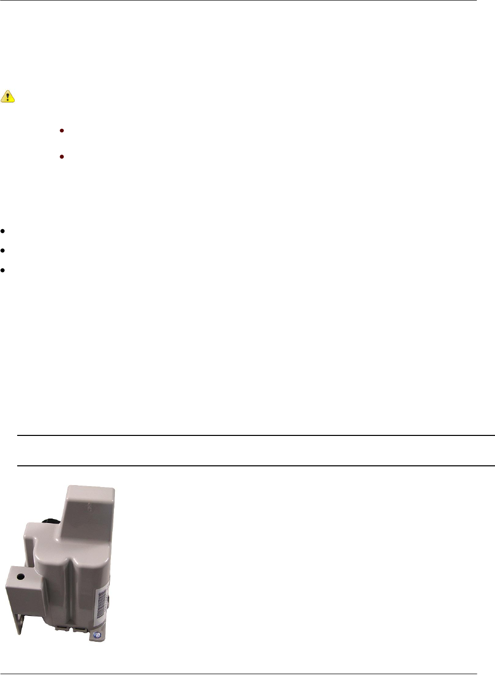
The 100W may be mounted to a flat surface using the base tab.
Caution Observe the following guidelines for mounting the 100W using the wall mount
procedure:
Endpoint positioning other than upright could negatively affect radio performance
and battery life.
Use only Itron-approved splice kits or inline connectors.
Required Base Mounting Tools and Hardware
Drill and drill bits appropriate for mounting location material.
Common hand tools for the selected fastening method.
Mounting screws: #10 size pan head screws appropriate for the wall or pit box material.
To install the 100W endpoint using the base mount procedure
1. Select a flat surface.
2. Position the endpoint vertically.
3. Mark the mounting-hole location.
4. Drill a pilot hole in the mounting location material. Follow the screw manufacturer's recommendation for
the pilot hole size.
5. Position the 100W and insert a #10 pan head screw in the base mounting tab. Carefully tighten the
mounting screw until the 100W is secure.
Caution Do not over-tighten the mounting screws. Over-tightening the mounting screws may break the
endpoint mounting tabs.
Installing the 100W Endpoint
TDC-0909-002 100W and 100WP Pit Datalogging Water Endpoint Installation Guide 18
Proprietary and Confidential
Shelf Mount Installation
This section describes 100W endpoint installation using a shelf mount adapter to mount the endpoint in a pit
lid slot.
Caution Observe the following guidelines for mounting the 100W using the wall mount
procedure:
Endpoint positioning other than upright could negatively affect radio
performance and battery life.
Use only Itron-approved splice kits or inline connectors.
The pit lid and slot must have the correct dimensions for the 100W or 100WP assembly to fit
properly.
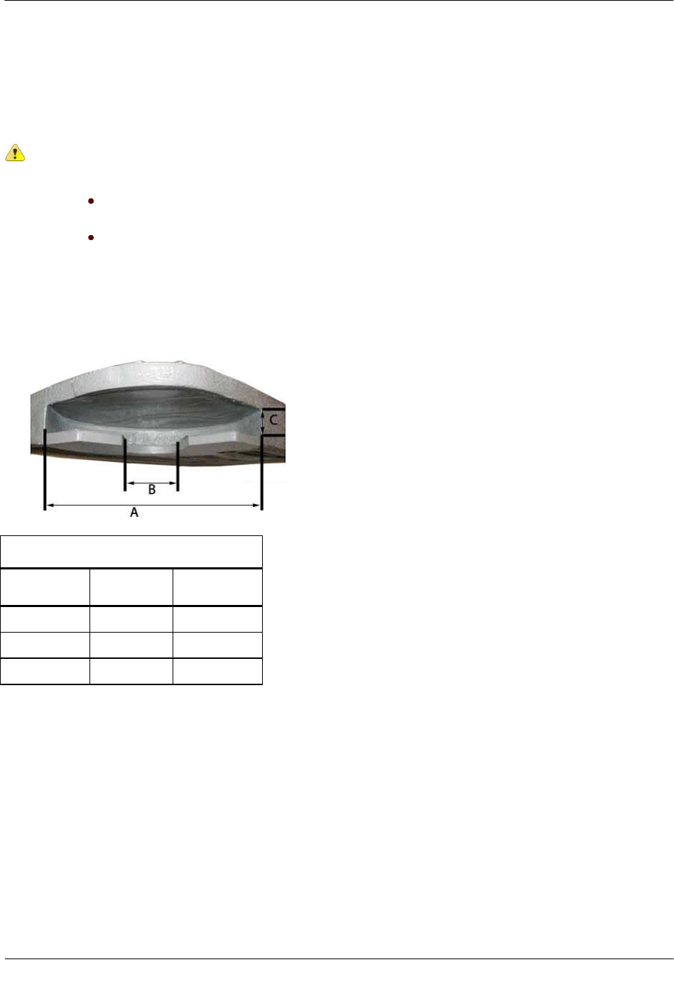
The following illustration and the accompanying table give pit lid slot dimensions for the shelf mount
installation method.
Pit Lid Slot Dimensions
Dimension
Minimum
(inches)
Maximum
(inches)
A
6 3/4
N/A
B
2
5 3/4
C
3/4
1
Required Tools and Hardware
Itron 100W Shelf Mount Kit
Installing the 100W Endpoint
TDC-0909-002 100W and 100WP Pit Datalogging Water Endpoint Installation Guide 19
Proprietary and Confidential
To install using the shelf mount adapter
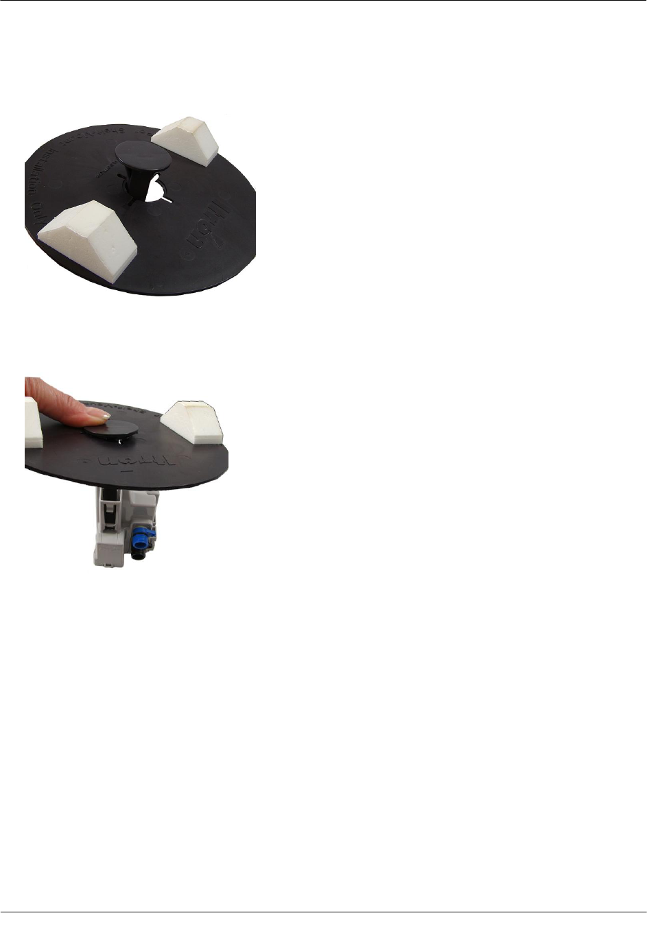
1. With the foam spacers facing up, insert the shelf mount adapter into the opening in the disk.
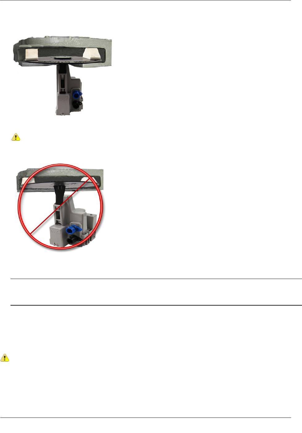
2. Push the adapter into the opening gently until the adapter snaps into place. Insert the shelf mount adapter
into the 100W endpoint antenna slot pushing firmly with your thumb until the adapter tab locks into place
in the 100W antenna slot opening.
Installing the 100W Endpoint
TDC-0909-002 100W and 100WP Pit Datalogging Water Endpoint Installation Guide 20
Proprietary and Confidential
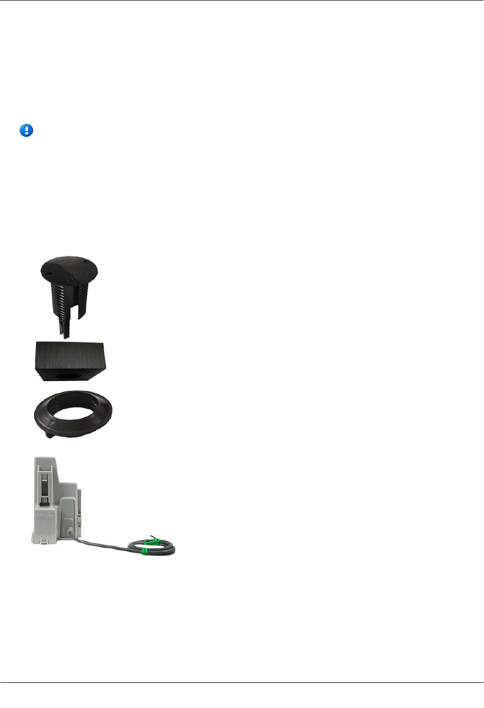
3. Slide the adapter assembly into the pit lid with the foam spacers positioned on each side of the pit lid slot.
Correct position for foam spacers
Caution Do not install the adapter assembly in a manner that provides little or
no support under disk's edge.
Incorrect mounting position for foam spacers.
4. The installed endpoint position must be vertical and upright when the lid is replaced on the pit.
Caution When placing the pit lid on to the pit box after the shelf mount adapter installation, use care to
avoid pinching or damaging the 100W meter cable. Any endpoint position other than upright may
negatively affect radio performance and battery life.
Through Lid Mount
This section provides instructions to mount the 100W endpoint in a pit lid with a drilled, round 1-3/4-inch, 1-
7/8-inch, or 2-inch hole.
Caution Some pit lids have a molded, recessed cavity that allows Itron 40W-1, 50W-1, and 50W-
2 ERT modules to sit flush with the top surface of the lid. However, the dome of the endpoint
retainer for the 100W endpoints has a smaller diameter and does not fill the pit lid cavity. This can
cause the cavity to become a trip hazard. Itron does not recommend using this type of pit lid with
100W endpoints.
Installing the 100W Endpoint
TDC-0909-002 100W and 100WP Pit Datalogging Water Endpoint Installation Guide 21
Proprietary and Confidential
Required Tools and Hardware
This mounting method requires the Pit Lid Mounting Kit. Refer to the 100W Installation Methods Overview
(PUB-1300-004) for guidance on which kit to install for different pit lid material and traffic conditions.
Pit Lid Mounting Kit (CFG-1300-004)
Note The Pit Lid Mounting Kit is not intended for applications involving vehicular traffic.
Use the Remote Antenna Kit in incidental traffic areas (such as residential environments).
To install in lids with holes using the Pit Lid Mounting Kit (CFG-0771-011)
This section provides the instructions to install the 100W endpoint in a pit lid with a hole using the Pit Lid
Mounting Kit (CFG-1300-004).
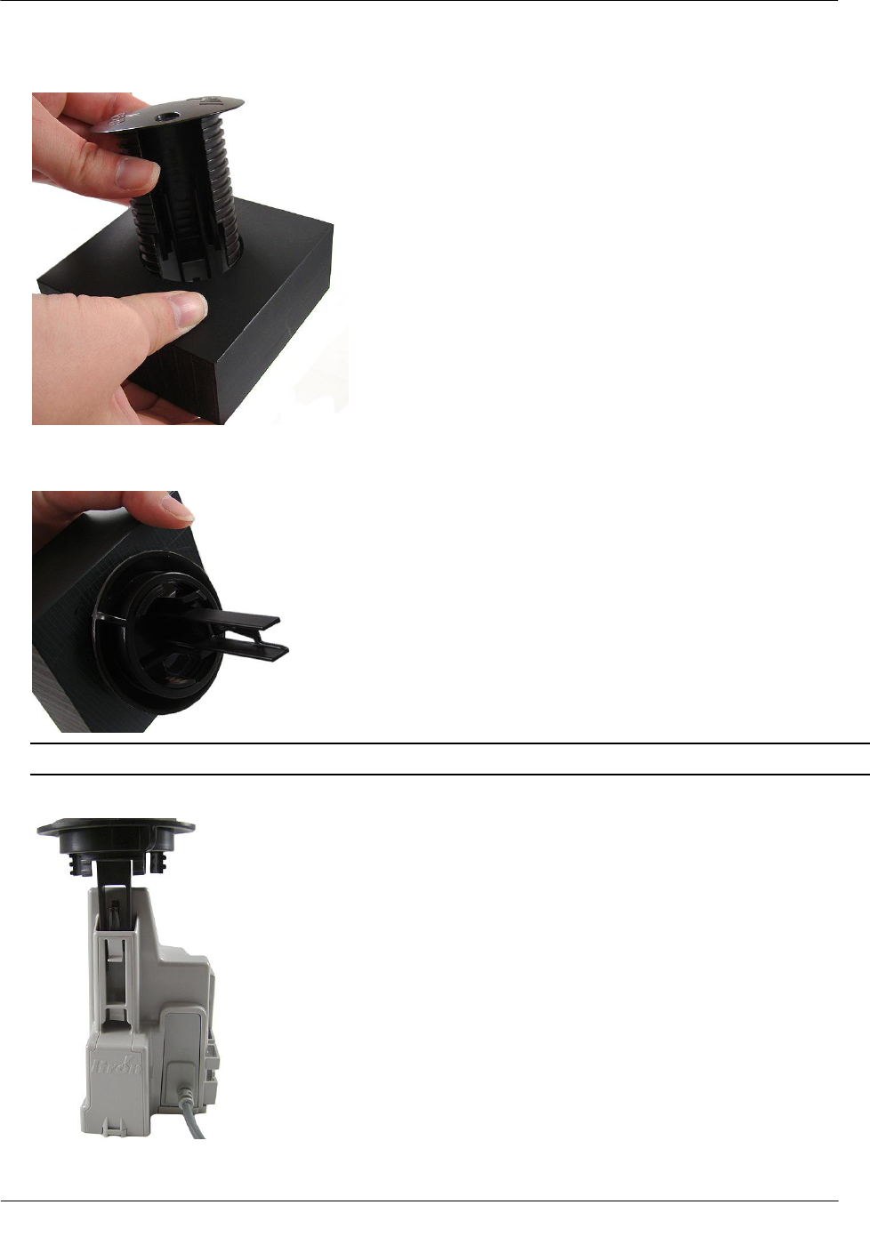
1. Verify you have the following items to complete the installation.
A
Retainer clip
B
Pit lid with a pre-drilled hole
(simulated pit lid material shown)
C
Retainer clip collar
D
100W endpoint
Installing the 100W Endpoint
TDC-0909-002 100W and 100WP Pit Datalogging Water Endpoint Installation Guide 22
Proprietary and Confidential
2. Insert the retainer clip into the pit lid hole with the convex surface on the top of the pit lid.
3. From the bottom side of the lid, screw on the threaded retainer clip collar until the beveled top rests
against the pit lid.
Note Ensure the beveled edge of the clip collar is toward the top of the pit lid.
4. Align and insert the retainer clip tab into the retainer clip receptacle on the 100W housing.
Installing the 100W Endpoint
TDC-0909-002 100W and 100WP Pit Datalogging Water Endpoint Installation Guide 23
Proprietary and Confidential
5. Verify the clip locks into place in the housing.
Caution Carefully align the 100W through lid assembly. If the assembly is improperly aligned, the pit lid
may not close.
Pit Lid Mounting Kit installation is complete.
Installing the Endpoint in a New Lid
This section describes installation of the 100W endpoint in a pit lid without a drilled hole.
To install the 100W in new lids
1. Select a hole location with enough clearance on the bottom side of the lid to attach the threaded clip collar.
2. Drill a 1-3/4 inch hole in the lid.
3. See To install in lids with holes using the Pit Lid Mounting Kit on page 21 to complete installation in a
new lid.
Installing the 100W Endpoint
TDC-0909-002 100W and 100WP Pit Datalogging Water Endpoint Installation Guide 24
Proprietary and Confidential
Optional Leak Sensor Installation
Leak Sensors (LS) analyze water flow sound patterns to detect new, evolving, and pre-existing leaks. LS
analysis data is uploaded to mlogonline™ Network Leak Monitoring for data analysis and accessed through a
secure Internet portal unique to your utility. This section describes installation of the Leak Sensor (LS) in a
100W system.
The 100W endpoint stores 20 days of Leak Sensor data. On the 21st day, the 100W begins to write over stored
data in a first in, first out manner.
The 100W automatically detects the presence of connected Leak Sensors. The 100W will automatically detect
the Leak Sensor within 22.5 minutes and begin reading Leak Sensor data. To immediately detect the Leak
Sensor and begin reading data, perform a Check ERT with a handheld computer running FDM software.
The LS is used in conjunction with both indoor (basement) and outdoor (mounting on the exterior of the
house) 100W endpoint installations. LS devices are mounted on a water service pipe or meter insetter (meter
horn) and connect to the appropriate endpoint wires as described in To connect the Leak Sensor to the 100W
endpoint on page 25. The mounting bracket shipped with the Leak Sensor accommodates an (up to) 1-1/2-
inch OD pipe. An optional mounting bracket is available for pipe sizes (up to 2 1/2-inch OD).
Required Equipment
Equipment
Itron Part Number
Description
Leak Detection Sensor
LDS-0001-002
LDS with inline connector, environmental connector cap; 5-foot
cable, and mounting bolt (fits up to 1 1/2-inch OD pipe).
Optional mounting bracket
CFG-0349-002
Mounting bolt fits up to 2 1/2-inch OD pipe.
100W endpoint
ERW-1300-002
Dual port 100W for LS and environmental connector caps.
25-foot extension cable
CFG-0349-101
25-foot cable with coordinating connectors (LS blue connector,
register black connector).
100W LS environmental replacement
cap
MSC-0019-005
Protects Leak Sensor connector when the Leak Sensor is not
connected to the 100W endpoint.
Warning When the 100W or 100WP is installed but the Leak Sensor is not attached, you
must protect the blue Leak Sensor port with the environmental cap (MSC-0019-005). If you
remove the Leak Sensor from the 100W, the environmental cap must be replaced to protect
the connector.
Installing the 100W Endpoint
TDC-0909-002 100W and 100WP Pit Datalogging Water Endpoint Installation Guide 25
Proprietary and Confidential
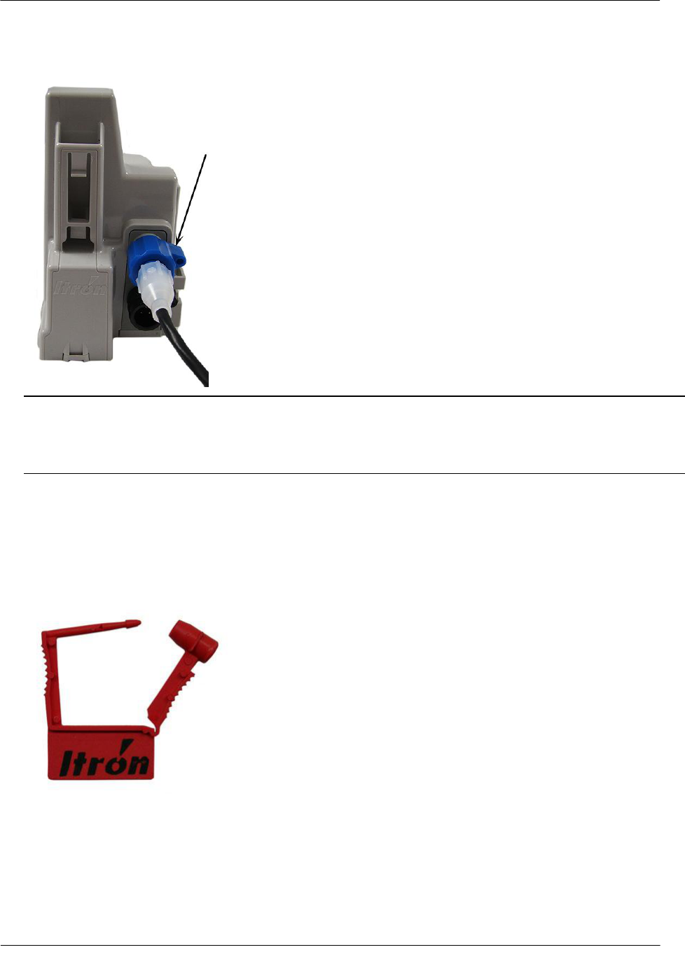
To connect the Leak Sensor to the 100W endpoint
Caution Verify you have the correct 100W or 100WP endpoint. Leak Sensors must mount to Port B (top
port) of the endpoint. Connecting the LS to Port A (bottom port) will cause electrical damage to the LS
and 100W endpoint.
1. Remove the environmental cap from the 100W endpoint blue connector (B).
B. 100W blue connector: Leak Sensor connection
A. 100W black connector: Register connection
2. Remove the environmental cap from the Leak Sensor connector. Verify the connectors (100W LS
connector and the Leak Sensor connector) are clean and dry.
3. Align the Leak Sensor connector with the endpoint's blue connector and insert.
Installing the 100W Endpoint
TDC-0909-002 100W and 100WP Pit Datalogging Water Endpoint Installation Guide 26
Proprietary and Confidential
4. Rotate the connector locking ring until the security holes align.
Caution Do not force the connector ends together. While holding the LS connector, engage the 100W
connector by rotating the locking ring until both connectors securely connect. Twist only the connector
locking ring, not the body of the connector. Twisting the connector body could damage the connector's
pins.
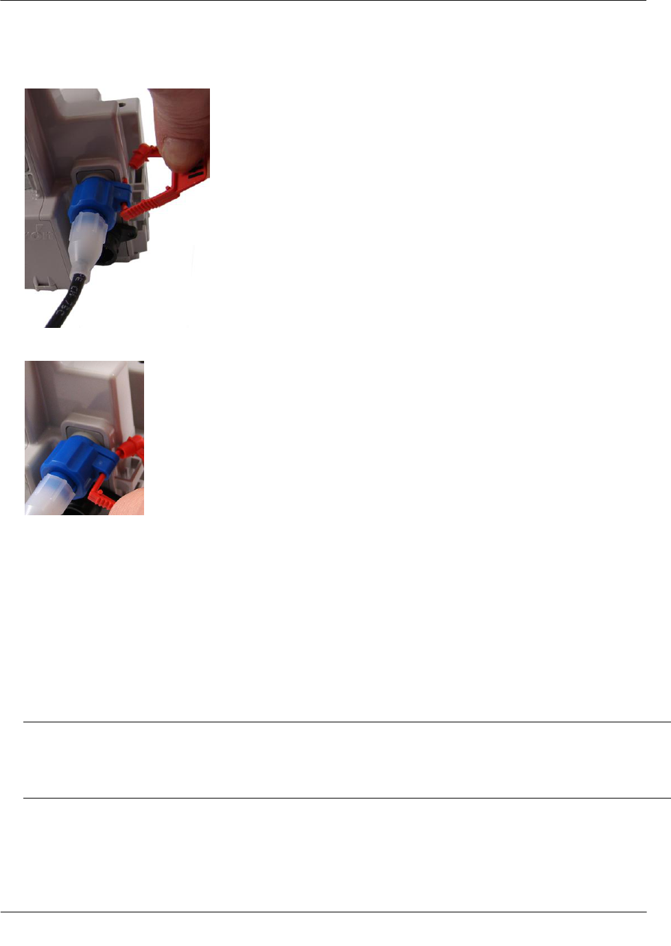
To attach an Itron Security Seal through the connector security hole
Required Materials
Itron Security Seal (MSC-0018-001)
Installing the 100W Endpoint
TDC-0909-002 100W and 100WP Pit Datalogging Water Endpoint Installation Guide 27
Proprietary and Confidential
1. Insert the pointed end of the security seal through the inline connector and the 100W connector security
holes.
2. Insert the pointed end of the security seal into the capped end and push until the seal locks.
This completes 100W endpoint and Leak Sensor connections.
Pipe Preparation
Clean any dust or dirt from the pipe to facilitate direct contact with the LS surface.
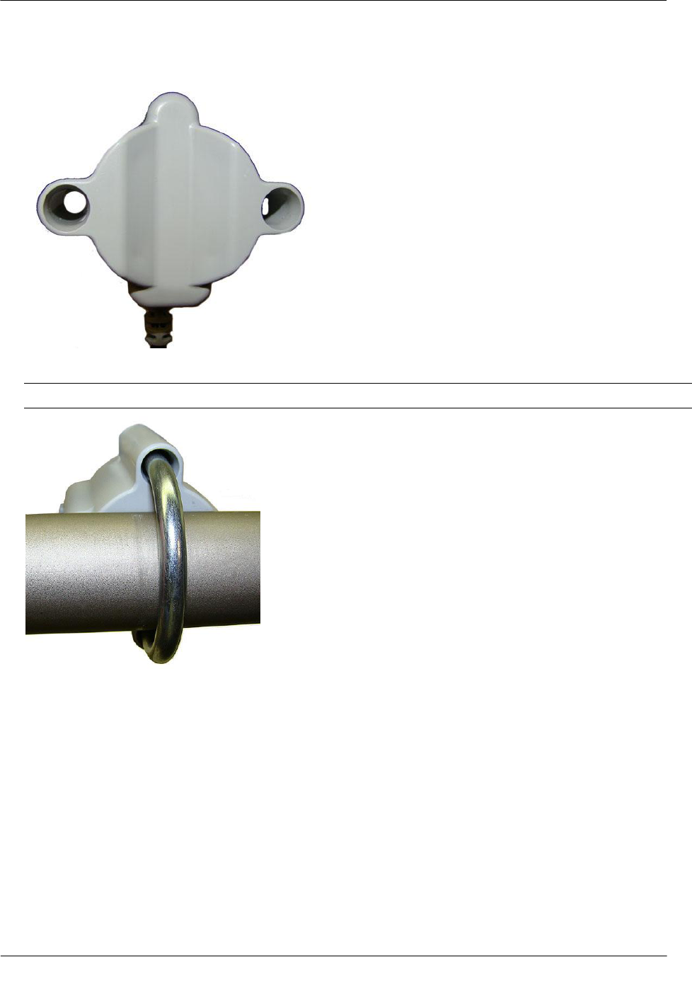
To install the Leak Sensor on a pipe or meter insetter
1. Select a Leak Sensor mounting location within 5-feet of the 100W endpoint. Mount the sensor on the
water input side of the meter.
Caution Mount the Leak Sensor on the water input side of the meter. Failure to follow this mounting
requirement could result in errors in the leak detection data. Installation requires Itron mounting hardware.
Repair costs and service charges relating to the use on non-compliant mounting hardware will be charged
to the customer. Contract Itron Support for more information.
Installing the 100W Endpoint
TDC-0909-002 100W and 100WP Pit Datalogging Water Endpoint Installation Guide 28
Proprietary and Confidential
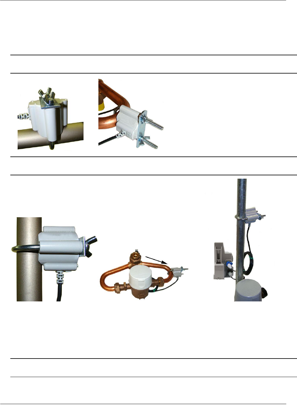
2. Verify the pipe’s mounting surface is free from dirt and debris. Place the curved surface of the LS against
the pipe.
3. Insert the mounting U-bolt over the pipe and into the LS mounting holes.
Caution Do not mount the Leak Sensor on a pipe coupler, joint, or nut.
Installing the 100W Endpoint
TDC-0909-002 100W and 100WP Pit Datalogging Water Endpoint Installation Guide 29
Proprietary and Confidential
4. Insert the mounting plate over the U-bolt's threaded screw ends. Attach the two wing nuts over the clamp
screw ends and tighten the wing nuts until snug (to a minimum of 5-inch pounds) to prevent device
rotation on the pipe. After you tighten the second wing nut, check the Leak Sensor to verify the device is
snug. If the sensor moves, tighten the wing nuts until there is no movement.
Caution Do not tighten the Leak Sensor to more than 20 inch-pounds. Over-tightening could damage the
Leak Sensor housing and/or the pipe.
Note Leak Sensor mounting orientation is not critical. Orient the Sensor to best accommodate your
installation. The most important installation practice is to mount the Sensor securely to the pipe.
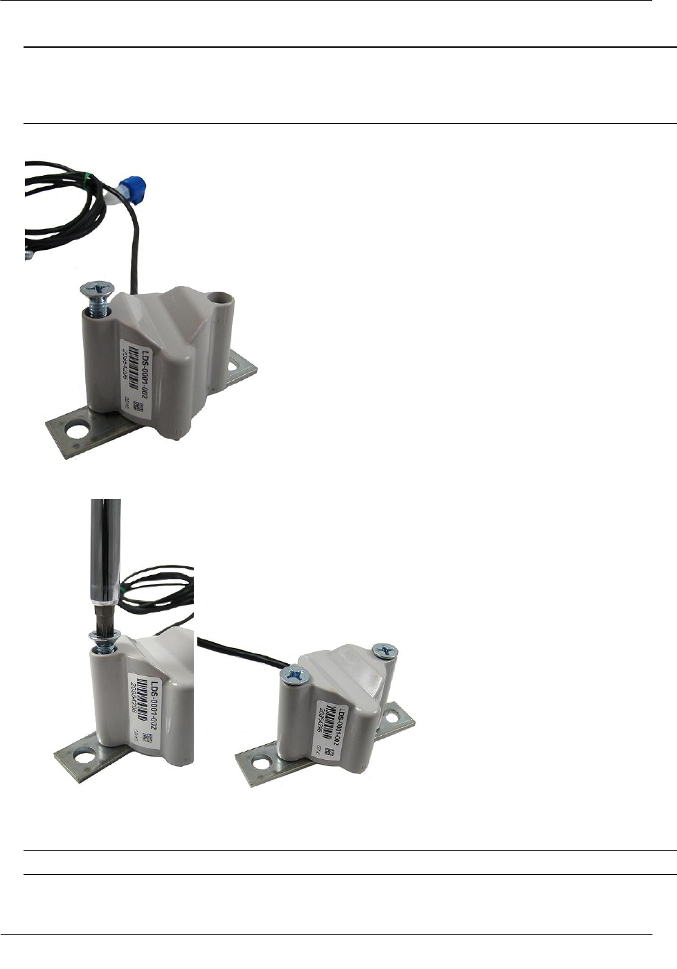
To install the Leak Sensor on a pipe (up to 2 1/2-inch OD)
1. Select a Leak Sensor mounting location within 5 feet of the 100W endpoint.
Note Leak Sensor mounting orientation is not critical. Orient the sensor to best accommodate your
installation. The most important installation practice is to fasten the Sensor securely to the pipe.
Installing the 100W Endpoint
TDC-0909-002 100W and 100WP Pit Datalogging Water Endpoint Installation Guide 30
Proprietary and Confidential
Caution Mount the Leak Sensor on the water input side of the meter. Failure to follow this mounting
requirement could result in errors in the leak detection data. Installation requires Itron mounting hardware.
Repair costs and service charges relating to the use on non-compliant mounting hardware will be charged
to the customer. Contract Itron Support for more information.
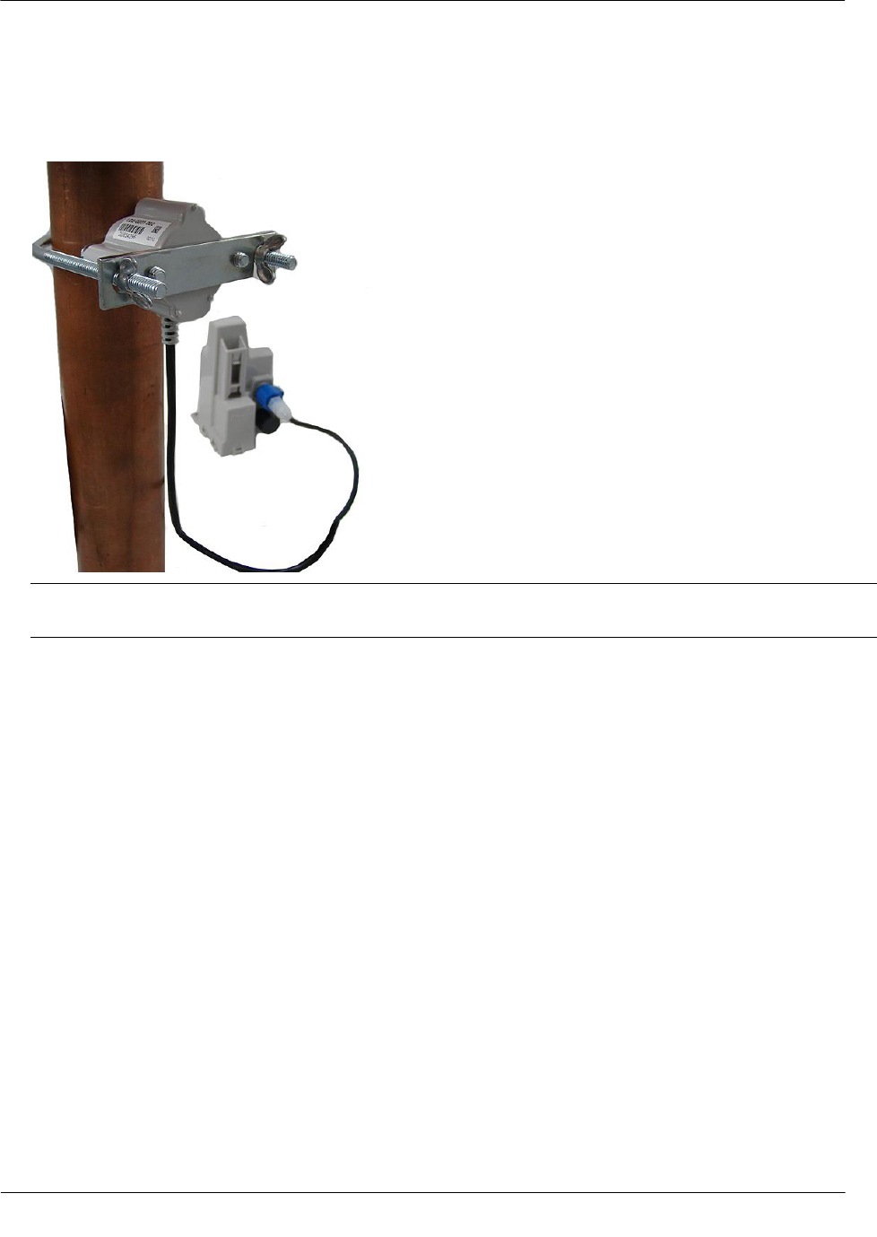
2. Insert the mounting plate screws into the holes on the Leak Sensor's curved surface.
3. Secure the mounting plate to the Leak Sensor.
4. Verify the pipe’s mounting surface is free from dirt and debris. Place the curved surface of the LS against
the pipe.
Caution Do not mount the Leak Sensor on a pipe coupler, joint, or nut.
Installing the 100W Endpoint
TDC-0909-002 100W and 100WP Pit Datalogging Water Endpoint Installation Guide 31
Proprietary and Confidential
5. Insert the U-bolt around the pipe and into the holes in the plate/Leak Sensor assembly. Secure the U-bolt
with the wing nuts. Tighten the wing nuts until snug (to a minimum of 5-inch pounds) to prevent device
rotation on the pipe. After the second wing nut is tightened, check the Leak Sensor to verify the device is
snug. If the sensor moves, tighten the wing nuts until there is no movement.
Caution Do not tighten the Leak Sensor to more than 20 inch-pounds. Over-tightening could damage the
Leak Sensor housing and/or the pipe.
TDC-0909-002 100W and 100WP Pit Datalogging Water Endpoint Installation Guide 32
Proprietary and Confidential
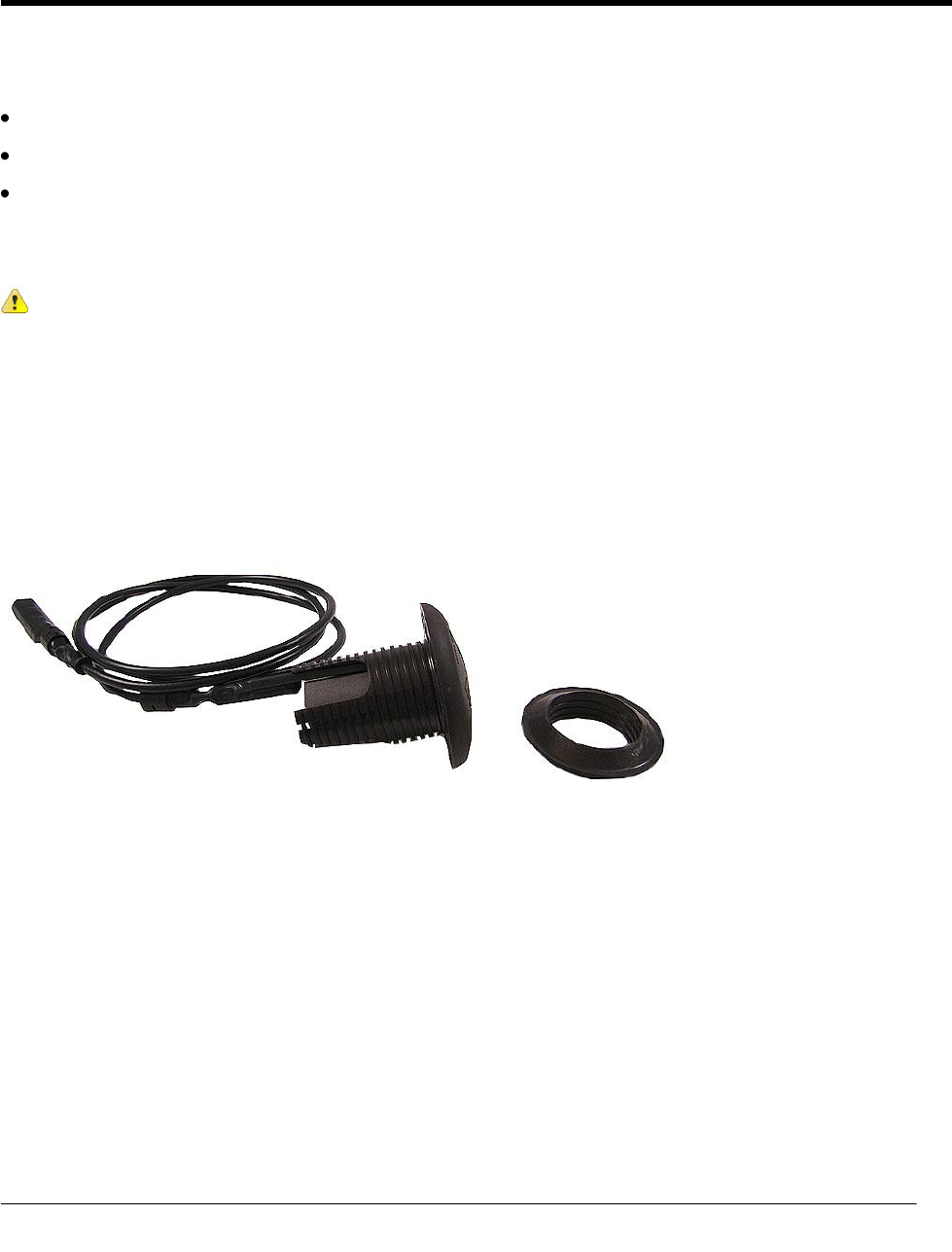
The optional 900 MHz remote mount antenna provides increased RF range coverage for the listed mobile
applications:
Meters located deep in a pit boxes.
Meters submerged in water for extended periods of time.
Meters in Fixed Network systems.
This section provides antenna mounting instructions through a pit lid and the instructions to connect the
antenna to the 100W.
Caution Optional remote antenna installation applies only to mobile applications.
Mounting the Remote Antenna
Metal lids on water pit boxes require a through-lid solution for optimal endpoint radio performance. The
remote antenna is designed to fit in a pit lid hole with a diameter between 1-3/4-inch to 2-inches and lid
thicknesses from 1/4-inch to 1-3/4-inch.
CH A P T E R 5
Optional Remote Antenna Installation
Optional Remote Antenna Installation
TDC-0909-002 100W and 100WP Pit Datalogging Water Endpoint Installation Guide 33
Proprietary and Confidential
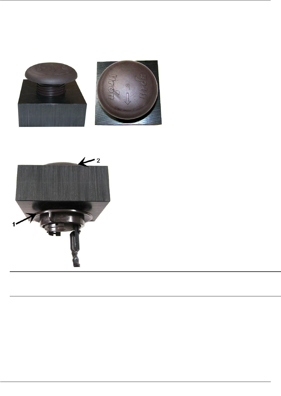
To mount the optional remote antenna through a pit lid
1. Insert the remote antenna into the pit lid hole with the convex surface on the top of the pit lid. (These
instructions show a simulated pit lid material.)
2. From the bottom of the lid, screw on the threaded collar two or three turns. Turn the threaded collar until it
is tight against bottom of the pit lid. Verify the antenna dome does not move up and down or shift laterally
.
Note Ensure the beveled edge (1) of the threaded collar is toward the top of the lid (2). The Itron-
recommended placement centers the remote antenna and takes up the extra space in mounting holes up to
2-1/2-inches.
Optional Remote Antenna Installation
TDC-0909-002 100W and 100WP Pit Datalogging Water Endpoint Installation Guide 34
Proprietary and Confidential
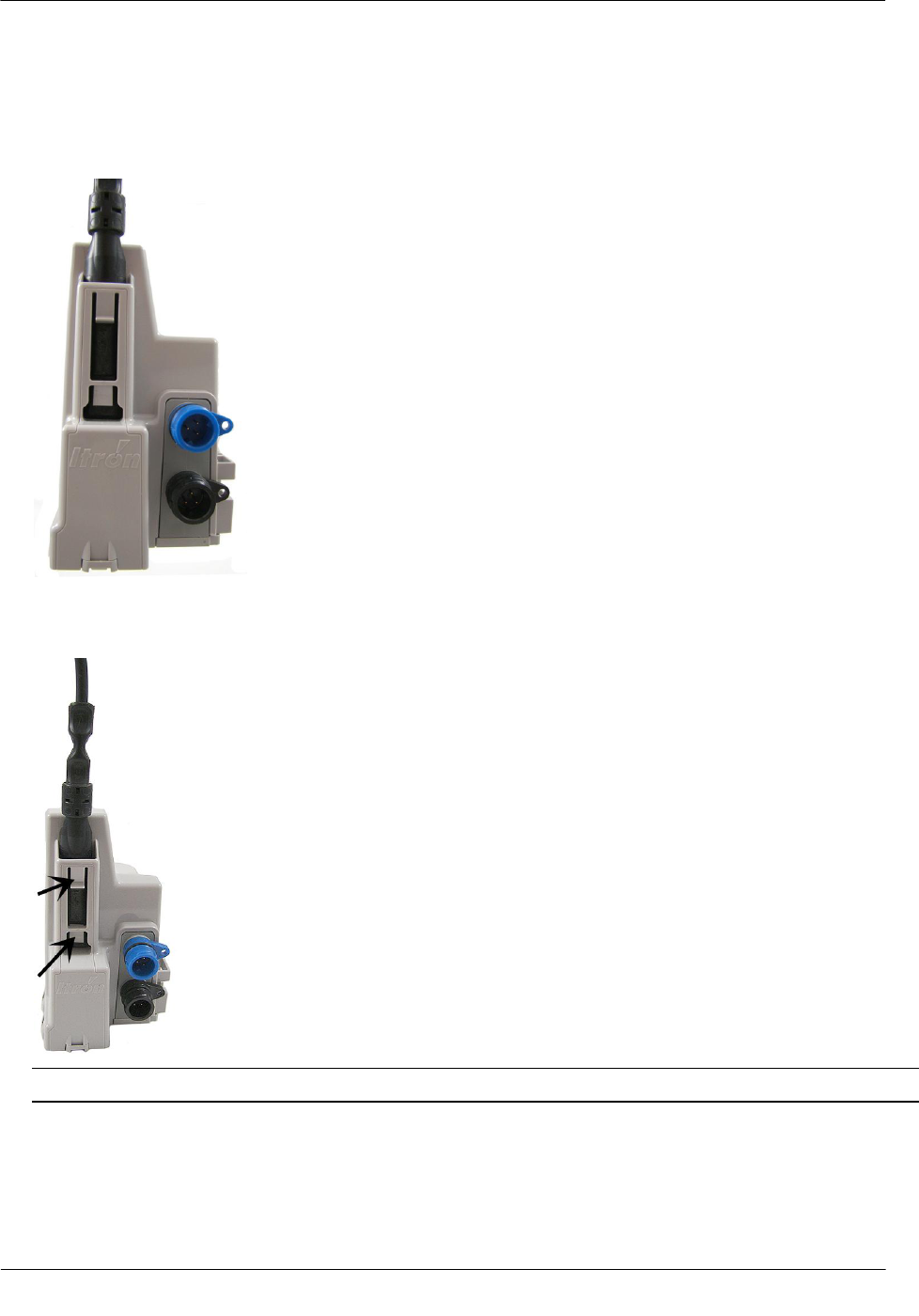
To connect the remote antenna coupler to the endpoint
1. Insert the remote antenna cable coupler into the endpoint's antenna slot with the flat side of the coupler
against the endpoint housing.
2. Push the antenna coupler into the antenna slot until the coupler locks into the tabs of the antenna slot.
Important Verify the antenna coupler locks with the antenna slot's tabs.
Remote antenna installation is complete.
TDC-0909-002 100W and 100WP Pit Datalogging Water Endpoint Installation Guide 35
Proprietary and Confidential
This section describes the 100W and 100WP connections to the water meter register using the inline
connector assembly. Follow the manufacturer's recommended procedure for installing the water meter register
on the meter.
To connect the inline connector
Note If an inline connector is not used and the 100W endpoint is already connected to the water meter
register, skip this step.
1. Remove the protective cover from the connector by twisting the two halves in opposite directions. Pull the
halves apart.
Caution Verify the connector halves are clean and dry before assembly.
If any of the following conditions occur, do not install the endpoint:
Any of the three pins are damaged or missing.
The O-ring is missing.
The cable is cut or nicked.
2. Connect the register cable to the endpoint connector. Holding the connectors by the back shells, rotate one
end to align the keyed slots. Push until snug. Slide the black coupling nut over the O-ring. Make sure the
O-ring stays seated. If the O-ring does not stay seated, disconnect and try again.
AP P E N D I X A
Using an Inline Connector
Using an Inline Connector
TDC-0909-002 100W and 100WP Pit Datalogging Water Endpoint Installation Guide 36
Proprietary and Confidential
3. Twist the register cable's black coupling nut to align the two tabs.
4. Install the security seal as shown. Push it until it snaps into place.
Note For future meter or endpoint servicing, break the security seal by pulling the seal apart. The original
protective connector covers can be reused if kept clean and dry. Install a new security seal after servicing
either device. To order more parts, see the Water Endpoint Ordering Guide (PUB-0063-001).
Caution Shield connectors with protective environmental covers. Do not leave an exposed connector in
the field.
Leak Sensor connector environmental cover: MSC-0019-005
Register connector environmental cover: MSC-0019-001, 1-year life.
The Leak Sensor environmental cap employs multiple seals to increase cap life. The Leak Sensor's cap
design allows utilities to install the endpoint and install the Leak Sensor at a future date.
TDC-0909-002 100W and 100WP Pit Datalogging Water Endpoint Installation Guide 37
Proprietary and Confidential
This section describes connecting the 100W endpoint to the water meter register using gel cap connectors.
Required Materials
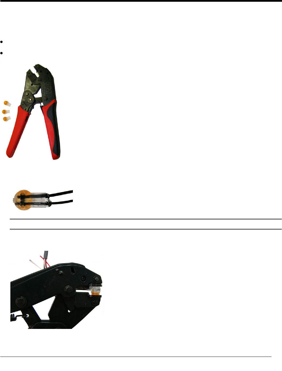
E-9R 3M® gel cap crimping tool
Itron Splice Kit (OEM-0034-002)
1. Push two wires as far as possible into the connector.
Caution Do not strip insulation from the ends of the wires before inserting them into the connector.
2. Carefully place the connector and wires into the jaws of the crimping tool. Make sure the wires remain
fully inserted in the gel-cap connector.
AP P E N D I X B
Using Gel-cap Connectors
Using Gel-cap Connectors
TDC-0909-002 100W and 100WP Pit Datalogging Water Endpoint Installation Guide 38
Proprietary and Confidential
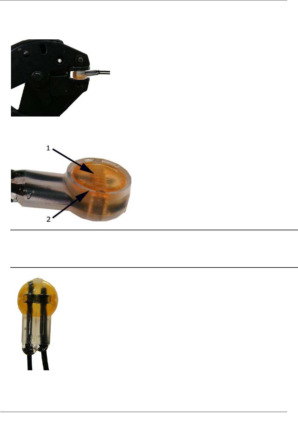
3. Crimp the connector by squeezing the handles until the connector cap is fully seated. Continue to apply
pressure for three seconds.
4. A connector is crimped properly when the top of the movable yellow center (1) is flush with the top of the
connector body (2).
Warning Crimping the connector forces some sealant out of connector. The sealant protects the inside of
the connector against insects, moisture, and other contaminants.
The sealant may cause minor eye and skin irritation. Avoid eye contact. Avoid prolonged or repeated skin
contact. Contact Itron Support for Material Safety Data Sheets (MSDS).
Using Gel-cap Connectors
TDC-0909-002 100W and 100WP Pit Datalogging Water Endpoint Installation Guide 39
Proprietary and Confidential
5. After you complete all endpoint to register wire connections, arrange the connectors in a single file.
6. Insert the connectors and wires into the splice tube until the connectors and wires completely immerse in
the tube's gel material.
7. Separate the cables to the sides and close the splice tube cover.
8. Discard any leftover materials from the customer premises.

TDC-0909-002 100W and 100WP Pit Datalogging Water Endpoint Installation Guide 40
Proprietary and Confidential
AP P E N D I X C
Troubleshooting

TDC-0909-002 100W and 100WP Pit Datalogging Water Endpoint Installation Guide 41
Proprietary and Confidential
Symbols & Numbers
100W and 100WP Models • 4
100W and 100WP Transmission Modes • 4
100W endpoint Accessories • 10
100W endpoints with Integral Connectors • 10
100W Operating Modes • 5
100WP Operating Modes • 5
A
About the 100W Endpoint • 3
B
Base Mount Installation • 17
Battery Life • 4
Before You Begin • 1
C
Connecting the 100WP to a Remote Meter
Register • 9
Connecting to a Meter Register Using a Cable • 7
Connecting to a Meter Register Using the Inline
Connector • 7
Connecting, Initializing, and Programming • 7
H
How This Document is Organized • 2
I
Initializing the 100W • 7
Installing and Connecting • 7
Installing in a New Lid • 23
Installing the 100W endpoint • 10
M
Mounting the Remote Antenna • 32
O
Optional Leak Sensor Installation • 24
Optional Remote Antenna Installation • 32
P
Pipe Preparation • 27
R
Related Documents • 2
Required Base Mounting Tools and Hardware • 17
Required Equipment • 24
Required Tools and Hardware • 12, 15, 18, 21
Rod Mount Installation • 11
S
Shelf Mount Installation • 18
T
Through-Lid Mount • 20
To connect the 100W to the register • 8
To connect the inline connector • 35
To connect the Leak Sensor to the 100W endpoint
• 25
To connect the remote antenna coupler to the
endpoint • 34
To install a cable tie to the connector • 11
To install in lids with holes using the Pit Lid
Mounting Kit (CFG-0771-011) • 21
To install the 100W endpoint on a rod • 12
To install the 100W endpoint using the base mount
procedure • 17
To install the 100W endpoint using the wall mount
procedure • 15
To install the 100W in new lids • 23
To install the Leak Sensor on a pipe (up to 2 1/2-
inch OD) • 29
To install the Leak Sensor on a pipe or meter
insetter • 27
To install using the shelf mount adapter • 19
Troubleshooting • 40
U
Using an Extension Cable • 9
Using an Inline Connector • 35
Using Gel-cap Connectors • 37
V
Verifying 100W endpoint Operation • 9
W
Wall Mount Installation • 15
Index