Itron 100WA AMR transceiver device for utility meters User Manual 4
Itron Inc AMR transceiver device for utility meters Users Manual 4
Itron >
Contents
Users Manual 4
Installing the 100W-R and 100WP-R Endpoints
TDC-0951-000 100W-R and 100WP-R Datalogging Water Endpoint Installation Guide 18
Proprietary and Confidential
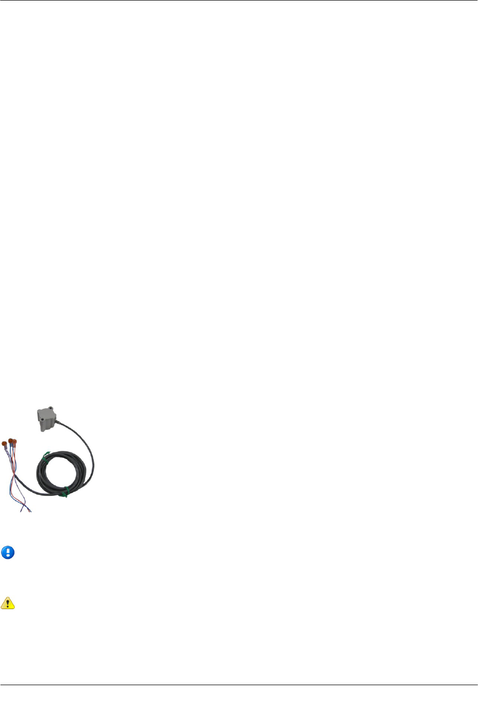
Optional Leak Sensor Installation
Leak Sensors (LS) analyze water flow sound patterns to detect new, evolving, and pre-existing leaks. LS
analysis data is uploaded to mlogonline™ Network Leak Monitoring for data analysis accessed through a
secure Internet portal unique to your utility. This section describes installation of the Leak Sensor (LS) in a
100W-R system.
The 100W endpoint stores 20 days of Leak Sensor data. On the 21st day, the 100W begins to write over stored
data in a first in, first out manner.
The 100W automatically detects the presence of connected Leak Sensors. The 100W will automatically detect
the Leak Sensor within 22.5 minutes and begin reading leak sensor data. To immediately detect the Leak
Sensor and begin reading data, perform a Check ERT with a handheld computer running FDM software.
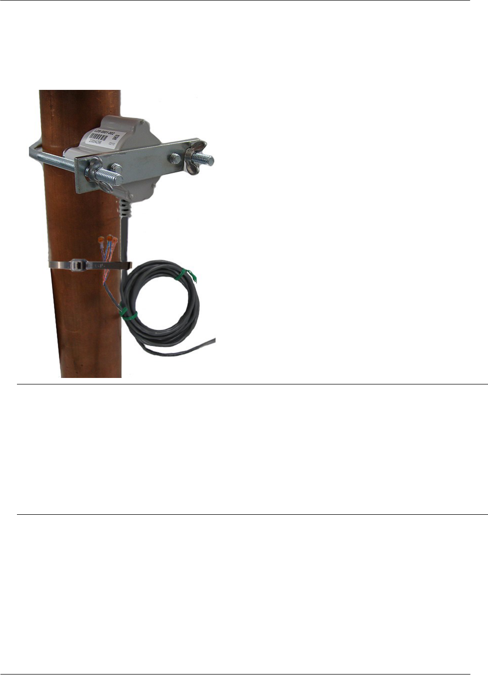
The LS is used in conjunction with both indoor (basement) and outdoor (mounting on the exterior of the
house) 100W-R and 100WP-R endpoints. LS devices are mounted on a water service pipe or meter insetter
(meter horn) and connect to the appropriate endpoint wires as described in the following section, Connecting
the Leak Sensor to the 100W-R and 100WP-R Endpoints. The mounting bracket shipped with the Leak
Sensor accommodates an (up to) 1-1/2-inch OD pipe. An optional mounting bracket is available for pipe sizes
(up to 2 1/2-inch OD).
Connecting the Leak Sensor to the 100W-R and 100WP-R Endpoints
Connecting a Leak Sensor to the 100W-R and 100WP-R endpoints requires a Leak Sensor enabled endpoint.
See 100W-R and 100WP-R Models on page 3. Connect the endpoint flying lead wires to the Leak Sensor
(using gel cap connectors, see Using Gel Cap Connectors on page 32) matching wire colors to complete the
three connections.
See the previous section, Optional Leak Sensor Installation, for Leak Sensor mounting information.
Note If the endpoint will mount on the exterior of the house but the Leak Sensor is on a pipe on
the interior, the Leak Sensor cable must run through a hole in the wall before connecting it to
the endpoint. Mount leak sensor gel cap connections securely to the mounting pipe.
Caution Extension cable lengths must not exceed 300 ft. Extension cabling from Itron is
stranded, tinned, and pre-bonded for reliability and proper connection to gel cap connectors.
Extension cabling manufactured by non-approved Itron manufacturers may result in unreliable
and problematic connections. Contact Itron Support for more information.
Installing the 100W-R and 100WP-R Endpoints
TDC-0951-000 100W-R and 100WP-R Datalogging Water Endpoint Installation Guide 19
Proprietary and Confidential
Pipe Preparation
Clean any dust or dirt from the pipe to facilitate direct contact with the LS surface.
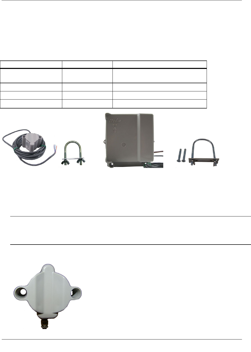
Required Equipment
Equipment
Itron Part Number
Description
Leak Detection Sensor
LDS-0001-001
LDS with bracket; 5-foot cable, and mounting bolt
(fits up to 1 1/2-inch OD pipe).
Optional mounting bracket
CFG-0349-002
Mounting bolt fits up to 2 1/2-inch OD pipe.
100W-R Encoder Remote
ERW-1300-114
100W-R with Leak Sensor, 10" flying lead.
100W-R Pulser Remote
ERW-1300-116
100WP-R with Leak Sensor, 10" flying lead.
Leak Sensor Standard mounting 100W remote endpoint Optional mounting
bracket bracket
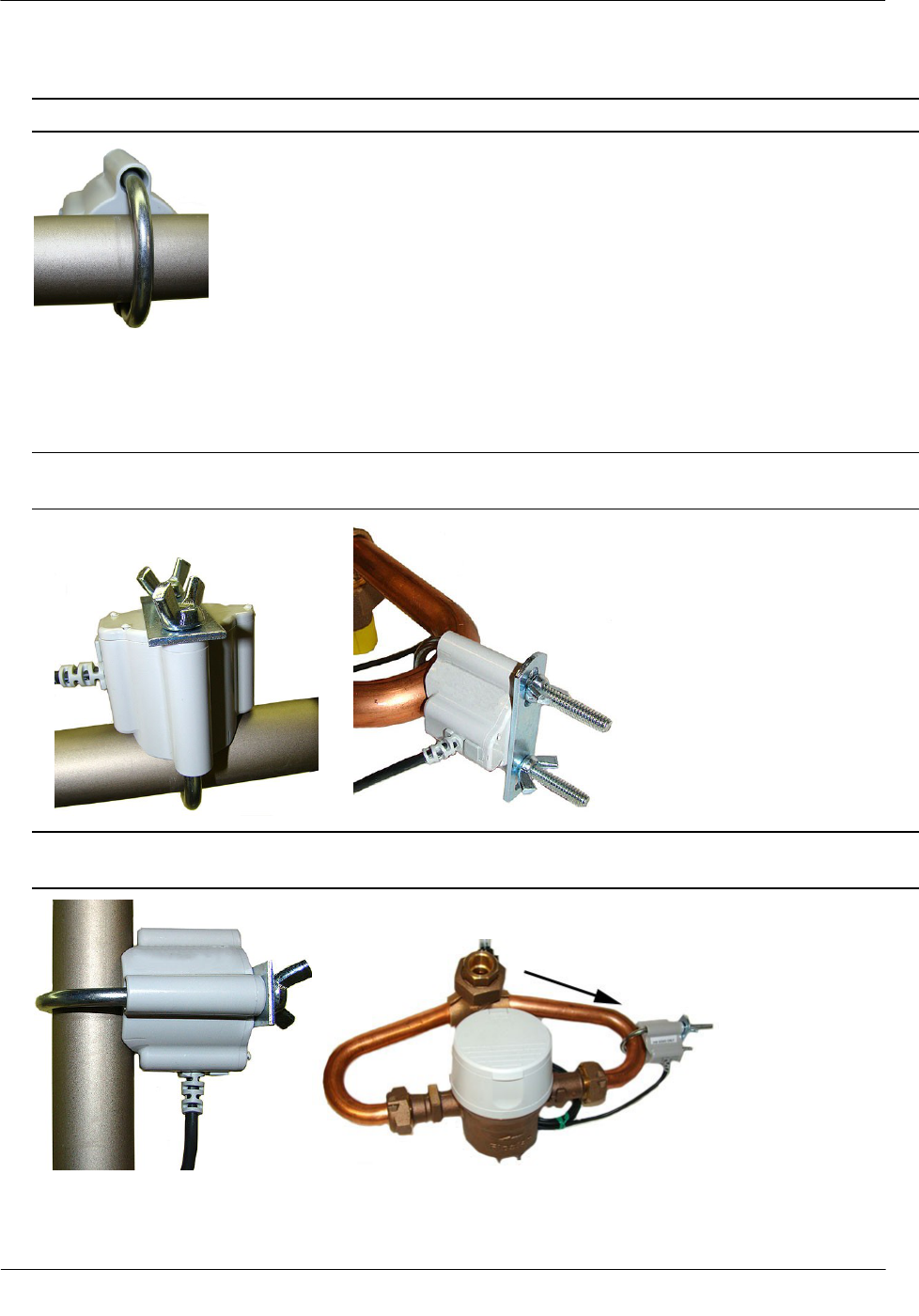
To install the Leak Sensor on a pipe or meter insetter
1. Select a Leak Sensor mounting location. Mount the sensor on the water input side of the meter.
Caution The Leak Sensor must be mounted on the water input side of the meter. Failure to follow this
mounting requirement could result in errors in the leak detection data. Installation requires Itron mounting
hardware. Repair costs and service charges relating to the use on non-compliant mounting hardware will
be charged to the customer. Contract Itron Support for more information.
2. Verify the pipe’s mounting surface is free from dirt and debris. Place the curved surface of the LS against
the pipe.
Installing the 100W-R and 100WP-R Endpoints
TDC-0951-000 100W-R and 100WP-R Datalogging Water Endpoint Installation Guide 20
Proprietary and Confidential
3. Insert the mounting U-bolt over the pipe and into the LS mounting holes.
Caution Do not mount the Leak Sensor on a pipe coupler, joint, or nut.
4. Insert the mounting plate over the U-bolt's threaded screw ends. Attach the two wing nuts over the clamp
screw ends and tighten the wing nuts until snug (to a minimum of 5-inch pounds) to prevent device
rotation on the pipe. After the second wing nut is tightened, check the Leak Sensor to verify the device is
snug. If the sensor moves, tighten the wing nuts until there is no movement.
Caution Do not tighten the Leak Sensor to more than 20 inch-pounds. Over-tightening could damage the
Leak Sensor housing and/or the pipe.
Note Leak Sensor mounting orientation is not critical. Orient the Sensor to best accommodate your
installation. The most important installation practice is to mount the Sensor securely to the pipe.
Installing the 100W-R and 100WP-R Endpoints
TDC-0951-000 100W-R and 100WP-R Datalogging Water Endpoint Installation Guide 21
Proprietary and Confidential
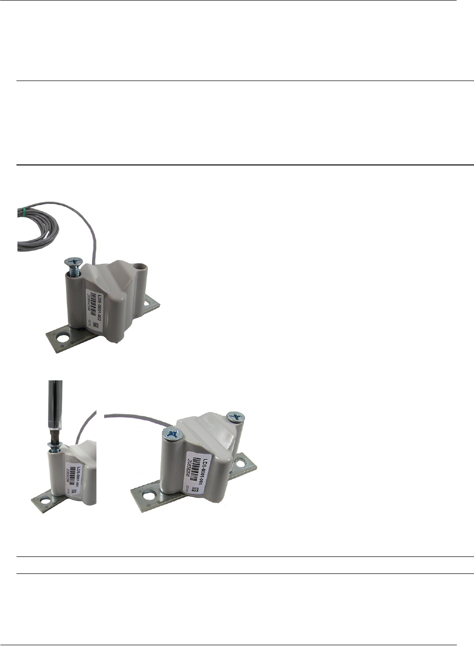
To install the Leak Sensor on a pipe (up to 2 1/2-inch OD)
1. Select a Leak Sensor mounting location within 5 feet of the 100W endpoint.
Note Leak Sensor mounting orientation is not critical. Orient the Sensor to best accommodate your
installation. The most important installation practice is to fasten the Sensor securely to the pipe.
Caution The Leak Sensor must be mounted on the water input side of the meter. Failure to follow this
mounting requirement could result in errors in the leak detection data. Installation requires Itron mounting
hardware. Repair costs and service charges relating to the use on non-compliant mounting hardware will
be charged to the customer. Contract Itron Support for more information.
2. Insert the mounting plate screws into the holes on the Leak Sensor's curved surface.
3. Secure the mounting plate to the Leak Sensor.
4. Verify the pipe’s mounting surface is free from dirt and debris. Place the curved surface of the LS against
the pipe.
Caution Do not mount the Leak Sensor on a pipe coupler, joint, or nut.
Installing the 100W-R and 100WP-R Endpoints
TDC-0951-000 100W-R and 100WP-R Datalogging Water Endpoint Installation Guide 22
Proprietary and Confidential
5. Insert the U-bolt around the pipe and into the holes in the plate/Leak Sensor assembly. Secure the U-bolt
with the wing nuts. Tighten the wing nuts until snug (to a minimum of 5-inch pounds) to prevent device
rotation on the pipe. After you tighten the second wing nut, check the Leak Sensor to verify the device is
snug. If the sensor moves, tighten the wing nuts until there is no movement.
Caution To ensure reliable Leak Sensor operation and a secure pipe mount:
● Do not tighten the Leak Sensor to more than 20 inch-pounds. Over-tightening could damage the
Leak Sensor housing and/or the pipe.
● Mount leak sensor gel cap connections securely to the mounting pipe.
● Extension cable lengths must not exceed 300 ft. Extension cabling from Itron is stranded, tinned,
and pre-bonded for reliability and proper connection to gel cap connectors. Extension cabling
manufactured by non-approved Itron manufacturers may result in unreliable and problematic
connections. Contact Itron Support for more information.
Remote Mount Installation
Connect the endpoint to the register as described in Programming and Connecting the 100W-R and 100WP-R
on page 6.
Using a back plate, create a template by drilling through a back plate lug slot to mark the position of the
screw. Use the drilled back plate as your mounting template.
The arrow on the endpoint must point up when installation is complete.
Installing the 100W-R and 100WP-R Endpoints
TDC-0951-000 100W-R and 100WP-R Datalogging Water Endpoint Installation Guide 23
Proprietary and Confidential
Required Tools and Hardware
Remote mount installation requires the following tools and hardware:
Remote Mount Kit (CFG-0771-021 or CFG-1300-003) includes the back plate, tamper seals, and
mounting screws)
Nut driver or similar tool
Phillips screwdriver
Drill and bits for mounting surface and screw size
To install on a flat surface
1. Select an installation location.
2. Using a back plate template, drill three pilot holes into the wall or other surface. The two bottom holes
should be level.
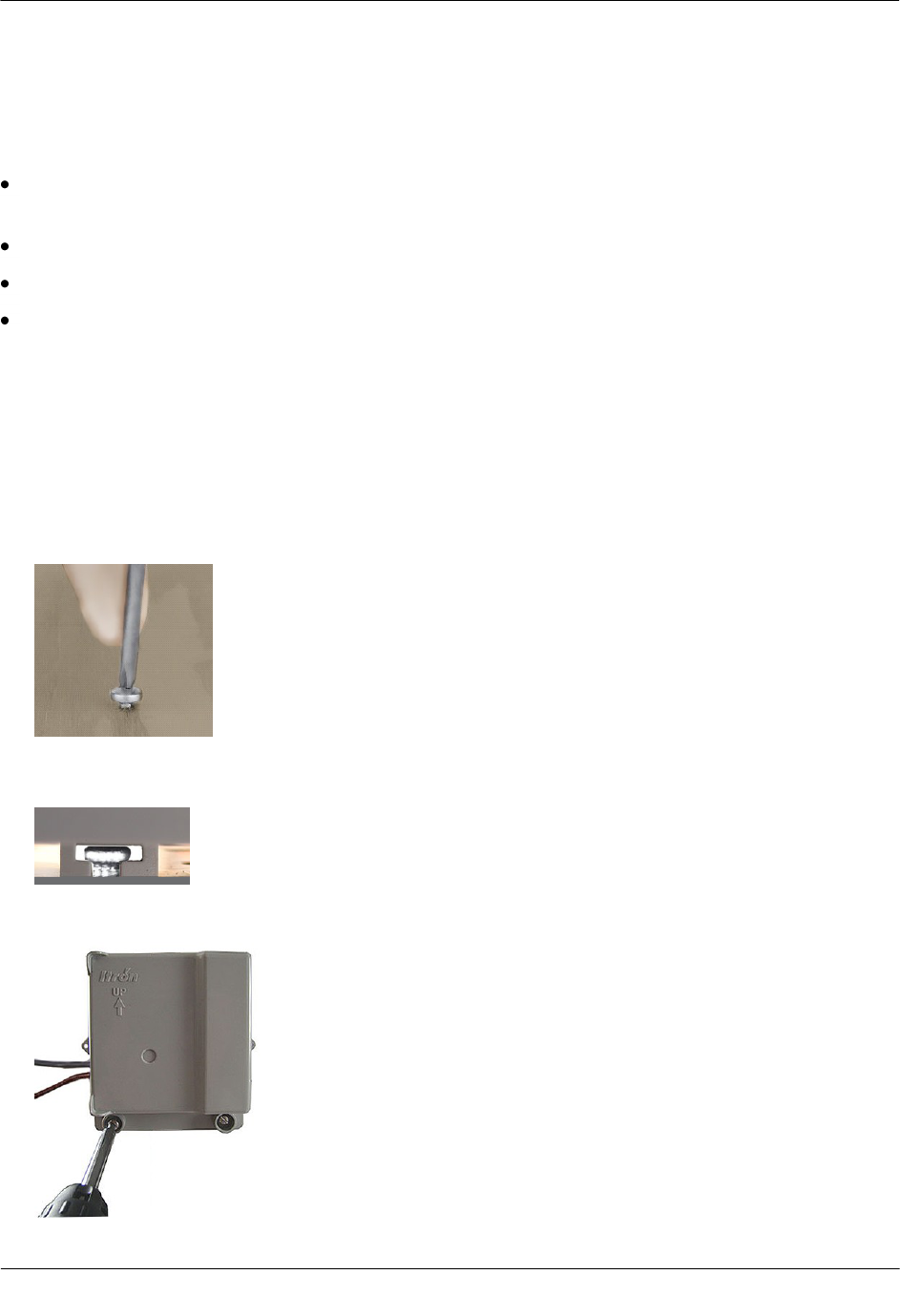
3. Screw a mounting screw for the lug slot into the surface, leaving approximately 1/8-inch of the screw
protruding. The lug slot should slide over the screw with a tight fit.
4. Slide the endpoint lug slot onto the mounting screw, pushing the endpoint upward until the screw head is
all the way into the slot.
5. Screw the endpoint to the wall using the remaining two mounting screws.
Installing the 100W-R and 100WP-R Endpoints
TDC-0951-000 100W-R and 100WP-R Datalogging Water Endpoint Installation Guide 24
Proprietary and Confidential
6. Insert a tamper seal over each mounting screw and drive into place with a nut driver or a similar tool.
Note A tamper seal is fully seated when the top of the tamper seal is approximately 1/16 inch below the
top of the screw recess.
7. Secure the cable using the provided cable ties.
Direct-Mounting to the Meter Register
Direct mounting endpoints to a meter register requires a register designed for that purpose. This section
describes 100W-R and 100WP-R installation for the following direct mount registers:
Badger ADE and RTR
Elster/AMCO (ABB) Scancoder, InVISION, and Digital
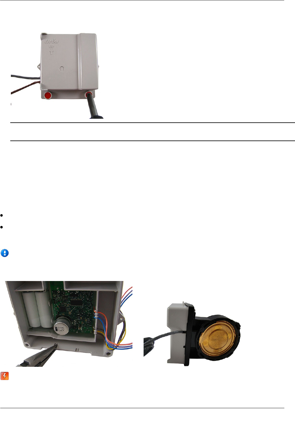
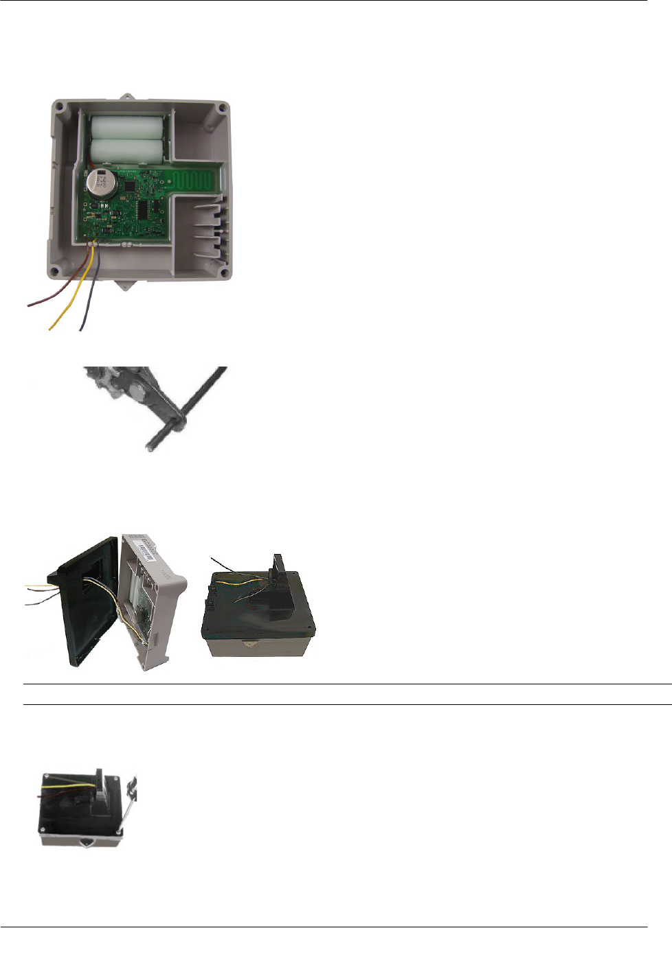
Note If you are installing an endpoint with Leak Sensor capability, use a needle-nose pliers to remove
one of the endpoint's housing knock-outs to accommodate the Leak Sensor cable. If your meter register
has a raised internal rim, remove the larger case knock-out.
Warning Do not use the direct mounting method in a pit environment. Use a pit endpoint for pit
environments. 100W-R and 100WP-R endpoints direct mounted in a pit environment are not
covered by the Itron warranty.
Installing the 100W-R and 100WP-R Endpoints
TDC-0951-000 100W-R and 100WP-R Datalogging Water Endpoint Installation Guide 25
Proprietary and Confidential
To install the 100W-R and 100WP-R endpoints to a Badger Direct-Mount register
Caution
Verify you have a Badger meter with a register designed for direct mount endpoints.
Check the part number on the label to make sure the module matches the meter.
Always install the module with the arrow on the housing pointing upward.
Note The register may or may not be mounted on the meter when performing the following steps.
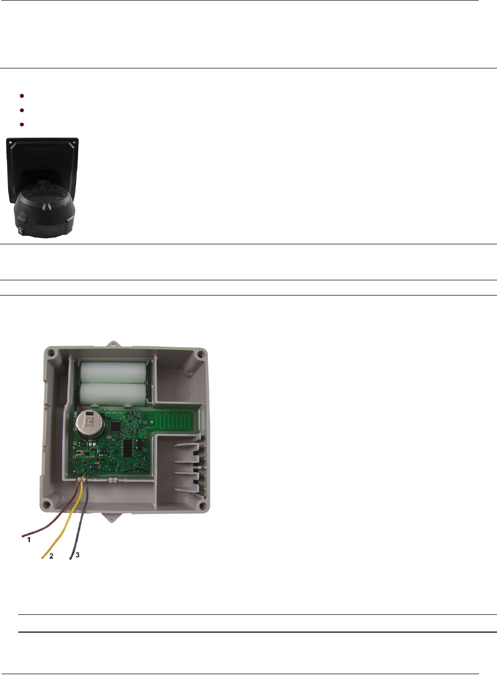
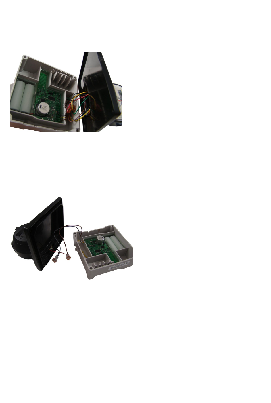
1. Direct-meter mounting requires a 100W-R endpoint for the Badger ADE register or a 100WP-R for the
RTR register. Both endpoints have three wires:
(1)
brown insulated wire
(2)
yellow insulated wire
(3)
gray insulated wire
Note For an RTR register, tuck the unused yellow wire into the housing.
Installing the 100W-R and 100WP-R Endpoints
TDC-0951-000 100W-R and 100WP-R Datalogging Water Endpoint Installation Guide 26
Proprietary and Confidential
2. Connect the endpoint wires to the register using gel-cap connectors (see Using Gel Cap Connectors on
page 32) following the 100W-R encoder to the Badger ADE register wire connections, (see Connecting
100W-R to a Remote Meter Register on page 6). After connecting the wires, carefully tuck the connectors
into the endpoint housing.
3. To wire the 100WP-R to the RTR 2-wire register, connect the endpoint wires to the 2-wire register using
gel-cap connectors (see Using Gel Cap Connectors on page 32). After connecting the wires, carefully tuck
the connectors into the endpoint housing.
4. To connect the 100WP-R pulser to the RTR 2-wire register, see Connecting the 100WP-R to a Remote
Meter Register on page 7. The endpoint's yellow wire is not used. Tuck the yellow wire back into the
endpoint housing with the gel-cap connectors.
Installing the 100W-R and 100WP-R Endpoints
TDC-0951-000 100W-R and 100WP-R Datalogging Water Endpoint Installation Guide 27
Proprietary and Confidential
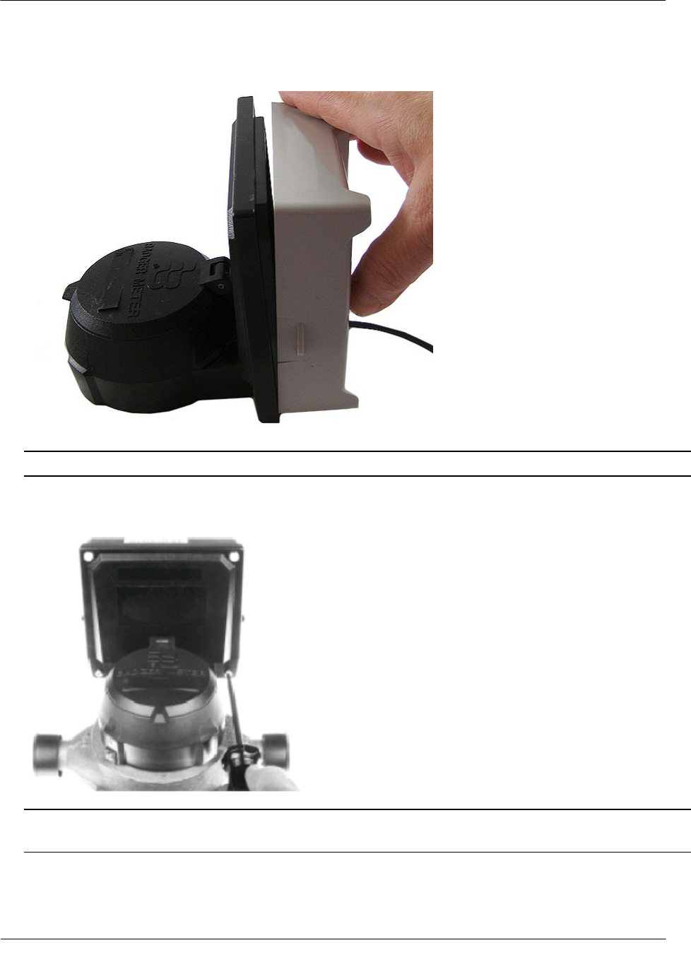
5. Place the endpoint on the register, ensuring the edge of the endpoint housing is seated properly around the
perimeter of the register as shown below.
Note A gasket is not required.
6. Install four Torx-head mounting screws (SCR-0010-005) as shown below and hand-tighten the screws.
Warning User Itron mounting screws (SCR-0010-005). Using the wrong mounting screws could crack
the plastic endpoint housing.
Installing the 100W-R and 100WP-R Endpoints
TDC-0951-000 100W-R and 100WP-R Datalogging Water Endpoint Installation Guide 28
Proprietary and Confidential
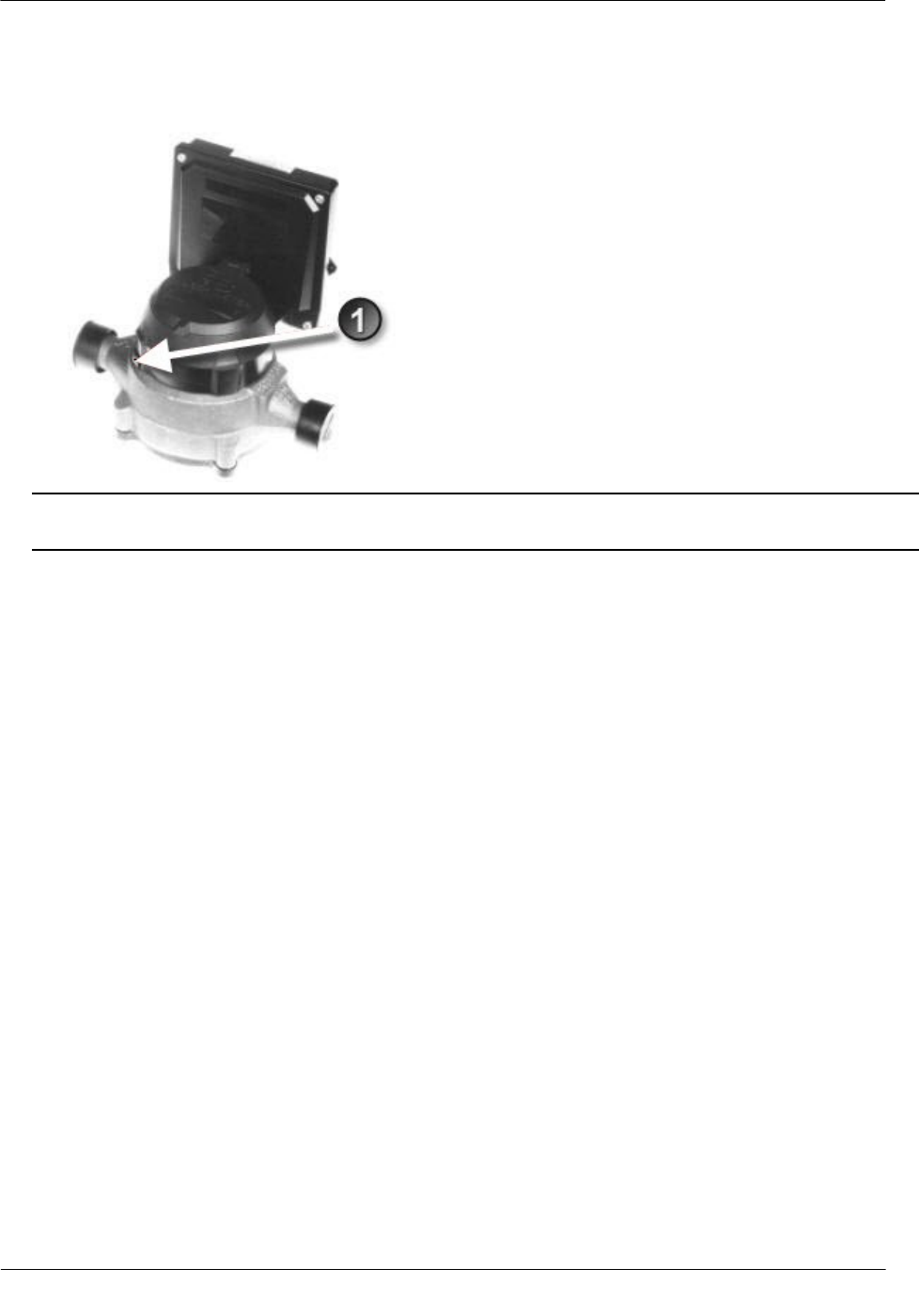
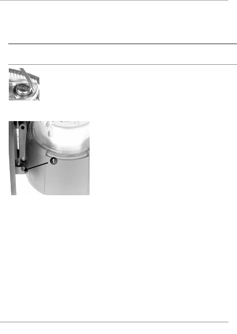
7. If you have not already done so, connect the register to the water meter and fully tighten the mounting
screw (1) as directed by Badger Meter.
Note Mount the register on the meter in one of four different positions with respect to the direction of
water flow (refer to the manufacturer's installation directions).
Installing the 100W-R and 100WP-R Endpoints
TDC-0951-000 100W-R and 100WP-R Datalogging Water Endpoint Installation Guide 29
Proprietary and Confidential
8. If the standard Torx screw is used (1), a wire seal is not necessary.
If the optional slotted and drilled RTR screw is used, install a wire seal through the drilled screw from (1)
to (2), or as specified by utility policy.
To install the Elster/AMCO (ABB) Scancoder, InVISION, or Digital Direct-Mount
Caution
Verify you have an Elster/AMCO meter with a register designed for direct mount endpoints.
Always install the endpoint right side up with the arrow on the housing pointed upward.
Note The register may or may not be mounted on the meter when performing the following steps.
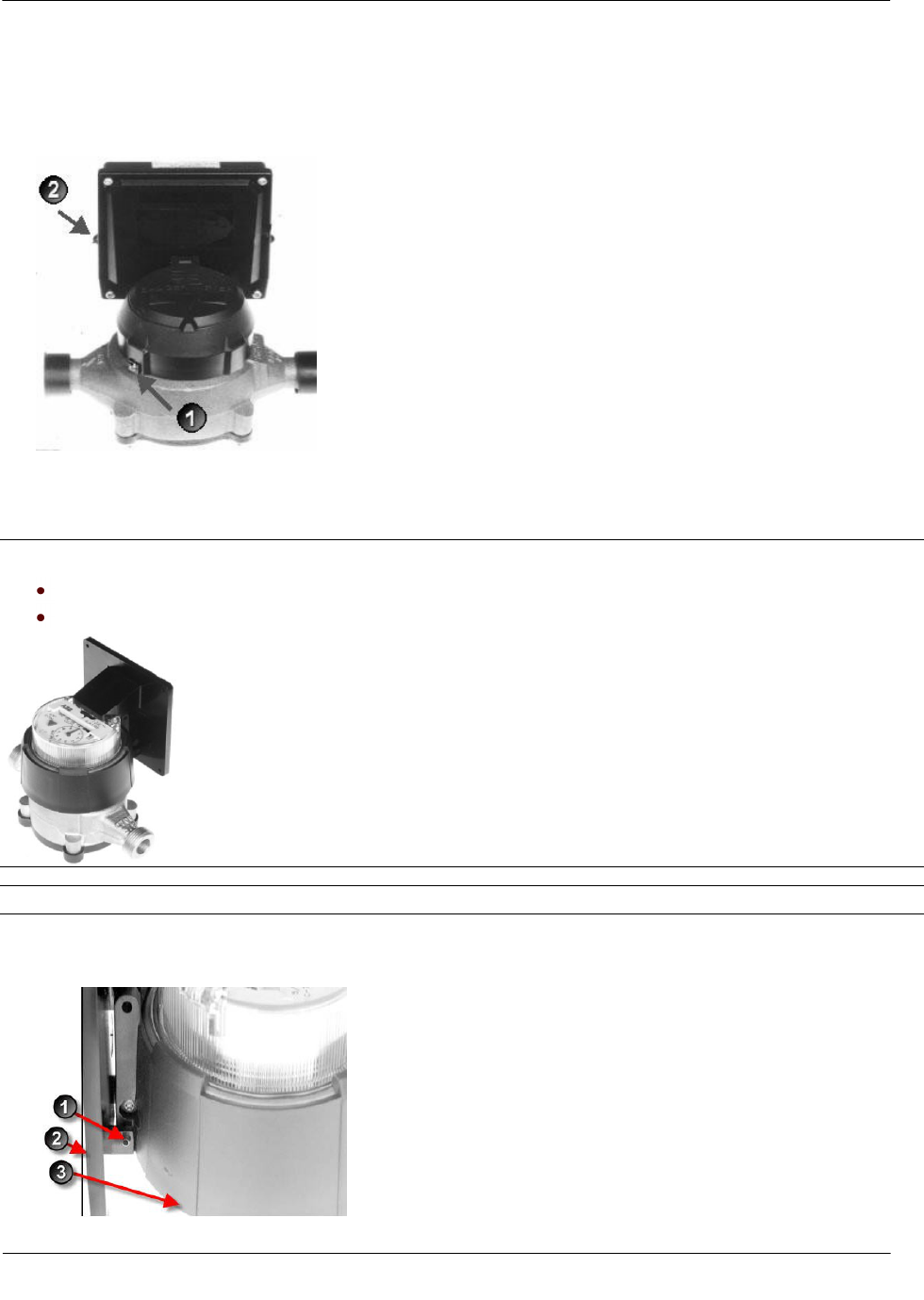
1. Push the hollow pin (1) completely out of its location and separate the endpoint mounting bracket (2) from
the meter register collar (3).
Installing the 100W-R and 100WP-R Endpoints
TDC-0951-000 100W-R and 100WP-R Datalogging Water Endpoint Installation Guide 30
Proprietary and Confidential
2. Installation requires a 100W-R endpoint for an InVISION or Scancoder register. Installation for a Digital
register requires a 100WP-R.
3. Strip 1/2-inch of insulation from the end of the brown, gray, and yellow wires.
4. Place the endpoint on the mounting bracket and route the yellow, gray, and brown wires through the
opening.
Note A gasket is not required.
5. Install four Torx-head mounting screws (Itron Part Number SCR-0010-005) as shown below. Hand
tighten each screw.
Installing the 100W-R and 100WP-R Endpoints
TDC-0951-000 100W-R and 100WP-R Datalogging Water Endpoint Installation Guide 31
Proprietary and Confidential
6. Connect the endpoint wires to the register screw terminals following the 100WP-R pulser to the
Elster/AMCO meter register wire connections, (see Connecting 100WP-R to a Remote Meter Register on
page 7). After connecting the wires, carefully tuck the connectors into the endpoint housing. Tighten all
screws securely.
Caution Install the wires around the screws in a clockwise direction (as shown) or the wires may come
out from under the screw heads as you tighten them. Also, verify insulation is NOT compressed under the
screw head, or the wire may not make good contact.
7. Install the module and mounting bracket on the meter register adapter collar.
8. Replace the hollow pin (1) you removed in step 1.
TDC-0951-000 100W-R and 100WP-R Datalogging Water Endpoint Installation Guide 32
Proprietary and Confidential
This section describes connecting the 100W-R and 100WP-R endpoints to the water meter register using gel
cap connectors.
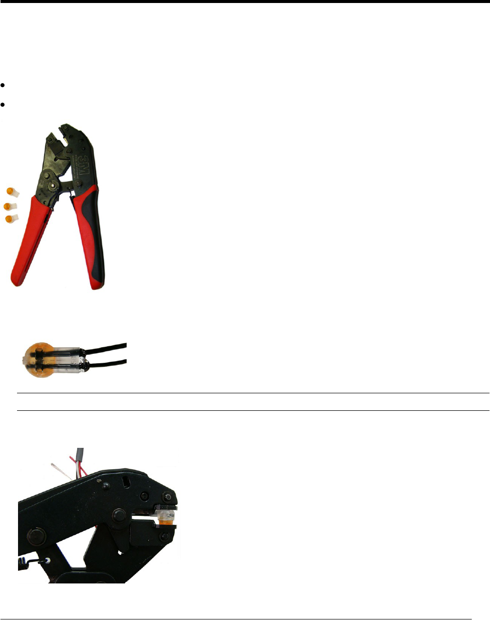
Required Materials
E-9R 3M® gel cap crimping tool
Gel cap connectors
1. Push two wires as far as possible into the connector.
Caution Do not strip insulation from the ends of the wires before inserting them into the connector.
2. Carefully place the connector and wires into the jaws of the crimping tool. Make sure the wires remain
fully inserted in the gel-cap connector.
AP P E N D I X A
Using Gel-cap Connectors
Using Gel-cap Connectors
TDC-0951-000 100W-R and 100WP-R Datalogging Water Endpoint Installation Guide 33
Proprietary and Confidential
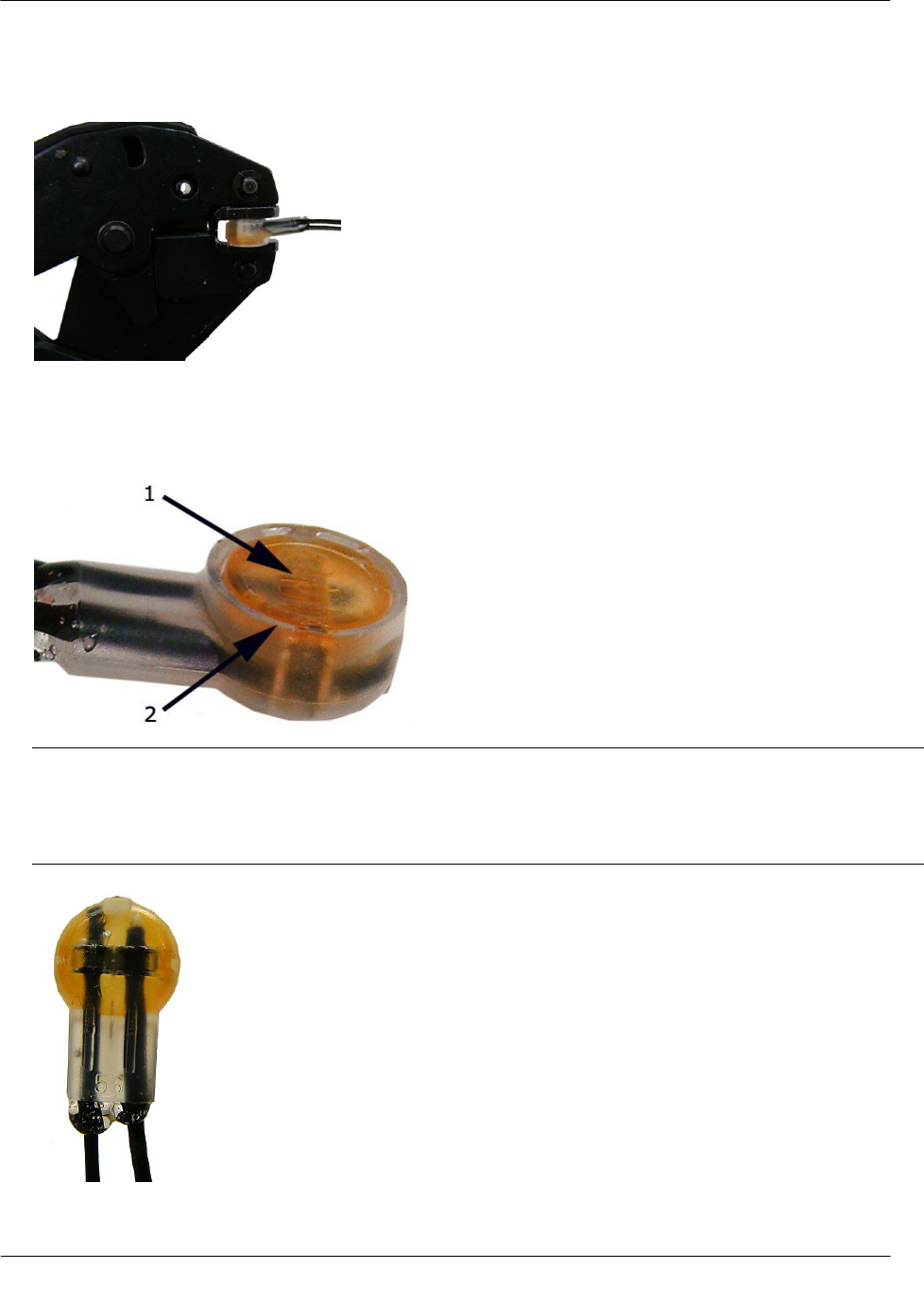
3. Crimp the connector by squeezing the handles until the connector cap is fully seated. Continue to apply
pressure for three seconds.
4. A connector is crimped properly when the top of the movable yellow center (1) is flush with the top of the
connector body (2).
Warning Crimping the connector forces some sealant out of connector. The sealant protects the inside of
the connector against insects, moisture, and other contaminants.
The sealant may cause minor eye and skin irritation. Avoid eye contact. Avoid prolonged or repeated skin
contact. Contact Itron Support for Material Safety Data Sheets (MSDS).

TDC-0951-000 100W-R and 100WP-R Datalogging Water Endpoint Installation Guide 34
Proprietary and Confidential
AP P E N D I X B
Troubleshooting

Index
TDC-0951-000 100W-R and 100WP-R Datalogging Water Endpoint Installation Guide 35
Proprietary and Confidential
Symbols & Numbers
100WP-R Operating Modes • 5
100W-R and 100WP-R endpoints Accessories •
13, 9
100W-R and 100WP-R Models • 3, 18
100W-R and 100WP-R Transmission Modes • 4
100W-R Operating Modes • 4
A
About the 100W-R and 100WP-R • 3
Attaching the Backplate • 9
B
Battery Life • 4
Before You Begin • 1
C
Connecting the 100WP-R to a Remote Meter
Register • 31, 26, 7
Connecting the 100W-R to a Remote Meter
Register • 26, 6
Connecting the Leak Sensor to the 100W-R and
100WP-R endpoints • 18
D
Direct-Mounting to the Meter Register • 9, 24
H
How This Document is Organized • 2
I
Initializing the 100W-R • 6
Installing the 100W-R and 100WP-R Endpoint • 9
O
Optional Leak Sensor Installation • 18
P
Pipe Mount Installation • 9, 13
Pipe Preparation • 19
Programming • 7
Programming and Connecting the 100W-R and
100WP-R • 22, 6, 3
R
Related Documents • 2, 8
Remote Mount Installation • 9, 22
Required Equipment • 19
Required Tools and Hardware • 23
T
To attach an encoder/pulser and leak sensor
backplate • 11
To attach an encoder/pulser only backplate • 10
To install on a flat surface • 23
To install tamper seals and cable ties • 16
To install the Elster/AMCO (ABB) Scancoder,
InVISION, or Digital Direct-Mount • 29
To install the Leak Sensor on a pipe (up to 2 1/2-
inch OD) • 21
To install the Leak Sensor on a pipe or meter
insetter • 19
To mount the 100W-R and 100WP-R endpoints on
the adapter plate • 16
To mount the adapter plate in other positions • 14
To mount the adapter plate on a vertical pipe • 13
Troubleshooting • 34
U
Using Gel Cap Connectors • 7, 18, 26, 26, 32
V
Verifying 100W-R and 100WP-R Endpoint
Operation • 8
Index