Itron 100WA AMR transceiver device for reading utility meter User Manual 1B
Itron Inc AMR transceiver device for reading utility meter Users Manual 1B
Itron >
Contents
Users Manual .1B

Water Solutions
100W-R and 100WP-R Datalogging Water
Endpoint Installation Guide
TDC-0951-001

Identification
100W-R and 100WP-R Datalogging Water Endpoint Installation Guide
03/08/2011 TDC-0951-001
Copyright
© 2010 - 2011 Itron, Inc. All rights reserved.
Confidentiality Notice
The information contained herein is proprietary and confidential and provided subject to the condition that (i) it is held in confidence except to the extent required otherwise by law and (ii) it is
used only for the purposes described herein. Any third party given access to this information is similarly bound in writing.
Compliance Statement
This device complies with Part 15 of the FCC Rules. These limits are designed to provide reasonable protection against harmful interference in a residential installation. Operation is subject to
the following two conditions:
• This device may not cause harmful interference.
• This device must accept any interference that may cause undesirable operation.
This device must be permanently mounted such that it retains a distance of 20 centimeters (7.9 inches) from all persons in order to comply with FCC RF exposure levels.
Compliance Statement
This equipment complies with policies RSS-210 and RSS-GEN of the Industry Canada rules.
Operation is subject to the following two conditions:
(1) this device may not cause interference, and
(2) this device must accept any interference, including interference that may cause undesired operation of the device.
Déclaration de conformité
Le présent appareil est conforme aux CNR d'Industrie Canada applicables aux appareils radio exempts de licence. L'exploitation est autorisée aux deux conditions suivantes :
(1) l'appareil ne doit pas produire de brouillage, et
(2) l'utilisateur de l'appareil doit accepter tout brouillage radioélectrique subi, même si le brouillage est susceptible d'en compromettre le fonctionnement.
Trademark Notice
Itron is a registered trademark of Itron, Inc.
All other product names and logos in this documentation are used for identification purposes only and may be trademarks or registered trademarks of their respective companies.
Warning To prevent ignition of flammable or combustible atmospheres, disconnect power
before servicing.
Warning Follow these procedures to avoid injury to yourself or others:
•The lithium battery may cause a fire or chemical burn if it is not disposed of properly.
• Do not recharge, disassemble, heat above 100° Celsius (212° Fahrenheit), crush, expose to
water, or incinerate the lithium battery. Fire, explosion, and severe burn hazard.
• Keep the lithium battery away from children.
• Replace the lithium battery only with batteries meeting Itron specifications. Any other
battery may cause a fire or explosion.
Warning This unit cannot be modified and is not repairable. Modification of this device could
cause non-compliance with FCC rules. Attempts to modify this device will void the warranty.
Warning Substitution of components may impair intrinsic safety.
Transportation Classification
The Federal Aviation Administration prohibits operating transmitters and receivers on all commercial aircraft. When powered, endpoints are considered operating transmitters and receivers and
cannot be shipped by air. All product returns must be shipped by ground transportation to Itron.
Suggestions
If you have comments or suggestions on how we may improve this documentation, send them to TechnicalCommunicationsManager@itron.com
If you have questions or comments about the software or hardware product, contact Itron Technical Support:
Contact
Internet: www.itron.com
E-mail: support@itron.com
Phone: 800 635 8725

TDC-0951-001 100W-R and 100WP-R Datalogging Water Endpoint Installation Guide iii
Proprietary and Confidential
Chapter 1 Before You Begin ........................................................................................ 1
Document Conventions ....................................................................................................................... 1
Document Purpose .............................................................................................................................. 1
How This Document is Organized ....................................................................................................... 2
Related Documents ............................................................................................................................. 2
Chapter 2 About the 100W-R and 100WP-R ............................................................... 3
100W-R and 100WP-R Models ........................................................................................................... 3
Battery Life .......................................................................................................................................... 4
100W-R and 100WP-R Transmission Modes ..................................................................................... 4
100W-R Operating Modes ................................................................................................................... 4
100WP-R Operating Modes ................................................................................................................ 5
Chapter 3 Programming and Connecting the 100W-R and 100WP-R....................... 7
Initializing the 100W-R ........................................................................................................................ 7
Connecting the 100W-R to a Remote Meter Register ........................................................................ 7
Connecting the 100WP-R to a Remote Meter Register ...................................................................... 8
Using an Extension Cable ................................................................................................................... 8
Programming ....................................................................................................................................... 9
Verifying 100W-R and 100WP-R Endpoints Operation ...................................................................... 9
Chapter 4 Installing the 100W-R and 100WP-R Endpoints ...................................... 10
100W-R and 100WP-R Endpoints Accessories ................................................................................ 10
Attaching the Backplate ..................................................................................................................... 10
Pipe Mount Installation ...................................................................................................................... 14
Optional Leak Sensor Installation ..................................................................................................... 19
Connecting the Leak Sensor to the 100W-R and 100WP-R Endpoints ................................. 19
Pipe Preparation ..................................................................................................................... 20
Required Equipment ............................................................................................................... 20
Remote Mount Installation ................................................................................................................. 23
Required Tools and Hardware ................................................................................................ 24
Direct-Mounting to the Meter Register .............................................................................................. 25
Appendix A Using Gel-cap Connectors .................................................................... 33
Appendix B Troubleshooting .................................................................................... 35
Index ............................................................................................................................. 36
Contents
TDC-0951-001 100W-R and 100WP-R Datalogging Water Endpoint Installation Guide 1
Proprietary and Confidential
Document Conventions
Convention
Example
Itron product part numbers are noted in
parentheses.
To install the endpoint (ERW-1300-XXX), do the following steps.
Hypertext links are in blue.
See the Copyright Page for identification information.
Note A Note indicates neutral or positive information that stresses or supplements important
points of the main text. A note supplies information that may apply only in special cases.
Caution A Caution advises users that failure to take or avoid a specified action could result in a
loss of data.
Warning A Warning advises users that failure to take or avoid a specified action could result in
physical harm to the user or the hardware.
Document Purpose
This document provides installation instructions for the 100W-R and 100WP-R endpoints including step-by-
step instructions for pipe mount, remote mount, and direct mount.
Caution Installing a remote endpoint or an integrated 100W endpoint and meter register in a
water pit box will void the product warranty. Remote endpoints are designed for interior and
exterior (on the side of buildings) installations only. Use a pit endpoint for pit-mount applications.
(Refer to the Water Endpoint Ordering Guide PUB-0063-001).
CH A P T E R 1
Before You Begin

Before You Begin
TDC-0951-001 100W-R and 100WP-R Datalogging Water Endpoint Installation Guide 2
Proprietary and Confidential
How This Document is Organized
This installation guide is organized with the following chapters:
Chapter
Description
1. Before You Begin
Information about this publication
2. About the 100W-R and 100WP-R
Overview of 100W-R and 100WP-R functionality.
3. Connecting, Initializing and
Programming
Instructions to initialize the 100W endpoint and
connect the endpoint to the register.
4. Installing the 100W-R and
100WP-R
Step-by-step endpoint installation instructions for:
Pipe mount
Optional Leak Sensor
Remote mount
Direct mount
Appendix A Using Gel-cap
Connectors
Instructions for installing gel-cap connectors.
Appendix B Troubleshooting
Tips for troubleshooting 100W endpoint operation.
Related Documents
Document Description
Itron Part Number
Field Deployment Manager Endpoint Tools Mobile Application Guide
TDC-0934-XXX
900 MHz Belt-Clip Radio User's Guide
TDC-0889-XXX
FC300 Getting Started Guide
TDC-0898-XXX
FC200 Series Getting Started Guide
TDC-0598-XXX
Water Endpoint Ordering Guide
PUB-0063-001
Water Meter Compatibility List
PUB-0063-002
mlogonline™ Network Leak Monitoring System User Guide
TDC-0792-XXX
Note XXX designates the document revision and is subject to change without notice.

TDC-0951-001 100W-R and 100WP-R Datalogging Water Endpoint Installation Guide 3
Proprietary and Confidential
The 100W-R and 100WP-R are high-power radio frequency automatic meter reading (AMR) devices that
attach to water registers to collect consumption usage and tamper data that the endpoint transmits to a data
collection device. The endpoint operates in both bubble-up mode and two-way modes.
The 100W-R and 100WP-R ship in Factory Mode. The endpoints acquire and transmit meter register data
within one hour following register connection. The endpoint transfers meter data immediately if the unit is
initialized with a handheld computer during installation (see Connecting, Initializing, and Programming on
page 7).
Caution Failure to initialize the endpoint may delay the initial reading up to 1 hour. The 100WP-R
endpoint will default to a consumption value of 0 if the endpoint is not programmed with Itron's
Field Deployment Manager (FDM).
The 100W-R and 100WP-R support protocols for a variety of meter manufacturer's registers. Refer to the
Water Meter Compatibility List (PUB-0063-002), for the list of supported meters and registers.
100W-R and 100WP-Rs feature the following capabilities:
Leak Detection and Reverse Flow Detection. 100W endpoints feature the same robust features as Itron's
60 series water endpoints to provide Leak Detection and Reverse Flow Detection. For more information
about Leak Detection and Reverse Flow Detection, see the Itron white paper Detecting Leaks and Reverse
Flow with 60 Series Endpoints (https://extranet-
kc.itron.com/Water%20Endpoints/Detecting%20Leaks%20and%20Reverse%20Flow%20with%2060%20
Series%20Endpoints.pdf).
Note The 100WP-R endpoint will not report reverse flow. Incremental encoded registers do
not provide a distinguishing signal while flowing in reverse.
Communication Error Indicators.
Last Good Read. The cable is cut.
Note Last Good Read may be an indicator of a damaged register.
Extended Cut Cable. The Last Good Read flag was set in the last 24 hours (FN mode) or the last 40
days (Mobile Mode).
100W-R and 100WP-R Models
100W Remote Endpoint Description
Itron Part Number
100W-R Encoder Remote, 10-inch flying lead
ERW-1300-113
100W-R Encoder Remote with Leak Sensor, 10-inch flying lead
ERW-1300-114
100WP-R Pulser Remote, 10-inch flying lead
ERW-1300-115
100WP-R Pulser Remote with Leak Sensor, 10-inch flying lead
ERW-1300-116
CH A P T E R 2
About the 100W-R and 100WP-R Endpoints

About the 100W-R and 100WP-R Endpoints
TDC-0951-001 100W-R and 100WP-R Datalogging Water Endpoint Installation Guide 4
Proprietary and Confidential
Battery Life
Powered by two non-replaceable, long-life lithium batteries, the 100W has an expected battery life of 20 years
when the endpoint operates in default Mobile or Fixed Network Operating mode. If the 100W endpoint is
programmed for Hard to Read Mobile Mode, the battery life is reduced to 13 years. To proactively indicate
the battery has reached a <10% useful battery life, a Low Battery flag is set to indicate impending battery
failure. Battery life is 15 years for the 100WP-R when endpoint cable lengths exceed 150 feet.
100W-R and 100WP-R Transmission Modes
The 100W-R and 100WP-R endpoints can be set to transmit in Fixed Network, Mobile High Power, Mobile
and Handheld, or Hard to Read Mobile, and Handheld Mode.
Fixed Network Mode. The 100W water endpoint transmits a high-powered NIM RF message every six
minutes and a contingency SCM RF message every minute.
Mobile and Handheld Mode. The 100W water endpoint transmits a medium-powered SCM RF
message every 9 seconds.
(Optional) Mobile High Power Mode. The 100W water endpoint transmits a high-powered SCM RF
message every 60 seconds.
(Optional) Hard to Read Mobile and Handheld Mode. The 100W water endpoint transmits a high-
powered SCM RF message every 30 seconds. The Hard to Read Mobile and Handheld Mode should only
be used for exceptionally hard-to-read applications.
Note The battery life is significantly affected in Hard to Read Mobile and Handheld Mode. You may use
the 900 MHz Remote Antenna to increase reading range.
An FCC license is not required to read 100W-R and 100WP-R endpoints.
100W-R Operating Modes
1. Factory Mode
100W-R endpoints ship from the factory in Factory Mode.
The endpoint's transmitter is off.
The endpoint's receiver bubbles-up to listen for a programming command.
100W-R encoder models attempt to read the register every hour.
Last good read and cut tamper flags may be set when a register is not connected.
If the 100W-R reads a connected register, the endpoint automatically moves to Run Mode (100W-R
only).

About the 100W-R and 100WP-R Endpoints
TDC-0951-001 100W-R and 100WP-R Datalogging Water Endpoint Installation Guide 5
Proprietary and Confidential
2. Run Mode
100W-R endpoint’s normal operation mode.
The 100W-R endpoint transmitted message is dependent on its factory settings for standard
consumption messages (SCM) or network interval message (NIM).
For SCM, the 100W default bubble-up rate is 9 seconds.
For NIM, the 100W default bubble-up rate is 6 minutes. When the endpoint is set for NIM, the
100W-R transmits a contingency SCM message every minute. Program FN mode with a
programming device to configure NIM mode.
100WP-R Operating Modes
The 100WP-R endpoint has three standard operating modes.
1. Factory Mode
100WP-R endpoints ship from the factory in Factory Mode.
The endpoint's transmitter is off.
The endpoint's receiver bubbles-up to listen for a programming command.
100WP-R endpoint encoder models attempt to read the register every hour.
Last good read and cut tamper flags may be set when a register is not connected.
If the 100WP-R reads a connected register, the endpoint automatically moves to Run Mode and defaults to
a zero consumption.
2. Run Mode
100WP-R endpoint’s normal operation mode.
The 100W transmitted message is dependent on its factory settings for standard consumption messages
(SCM) or network interval message (NIM).
For SCM, the 100WP-R default bubble-up rate is 9 seconds.
For NIM, the 100WP-R default bubble-up rate is 6 minutes. When the endpoint is set for NIM, the
100WP-R transmits a contingency SCM message every minute. NIM mode is configured by
programming NIM mode with a programming device.

About the 100W-R and 100WP-R Endpoints
TDC-0951-001 100W-R and 100WP-R Datalogging Water Endpoint Installation Guide 6
Proprietary and Confidential
3. Quiet Mode
OEMs can configure the endpoint for quiet mode after programming and direct mounting the 100WP-R in
a factory.
An endpoint is awakened from quiet mode and enters Run Mode in one of two ways:
Counting two pulses. The pulses are counted internal to the 100WP-R while it is in quiet mode.
Receiving a two-way command, such as a Read ERT using FDM.
If an endpoint installed in quiet mode is not bubbling up SCM or NIM messages, it may be due to zero
consumption on the endpoint, such as a vacant or vacation home. Initiate a two-way command (for
example, perform a Read ERT with FDM) before removing the unit.

TDC-0951-001 100W-R and 100WP-R Datalogging Water Endpoint Installation Guide 7
Proprietary and Confidential
This chapter provides the instructions to initialize the 100W-R, connect the endpoint to water meter registers
and program the 100WP-R.
Initializing the 100W-R
To initialize the 100W-R immediately, use one of the following handheld computers running Field
Deployment Manager (FDM) version 1.0 or later.
FC200SR handheld computer (Itron part number FC2-0005-004 or FC2-0006-004)
FC300 with SRead
For normal activation, connect the 100W-R to the water meter register. The endpoint polls for a register
every hour. The 100W-R automatically activates after the endpoint detects a register.
Connecting the 100W-R to a Remote Meter Register
Connect the wires from the endpoint to the register according to the following table.
100W-R Connections
Register Manufacturer
100W-R wire color
Brown (data)
Gray
(power/clock)
Yellow
(ground)
Register screw color designator
Elster AMCO Invision
R
GRN
BLK
Elster AMCO Scancoder
R
GRN
BLK
Elster AMCO evoQ4 (Q4000)
R
White
BLK
Hersey Translator
GRN
R
BLK
Badger ADE
GRN
R
BLK
Sensus ECR (all variants)
GRN
R
BLK
Sensus ICE
GRN
R
BLK
Itron (Actaris) Coder
GRN
R
BLK
Metron Famier
GRN
R
BLK
ProRead &
ProRead Auto Detect
R
BLK
GRN
Performance ETR
GRN
R
BLK
SevernTrent SM700
SmartMeter
(Sensus Protocol)
GRN
R
BLK
Neptune E-coder
R
BLK
GRN
CH A P T E R 3
Initializing, Connecting, and Programming

Initializing, Connecting, and Programming
TDC-0951-001 100W-R and 100WP-R Datalogging Water Endpoint Installation Guide 8
Proprietary and Confidential
Connecting the 100WP-R to a Remote Meter Register
Connect the 100WP-R wires from the endpoint to the register according to the following table.
100WP-R Connections
Register Manufacturer
100WP-R wire color
Brown
(signal)
Gray
(common)
Yellow
(tamper)
Register screw color designator
Elster Digital
BLK
GRN
R
Itron (Actaris) Cyble Sensor (2-
wire)
Either wire
Remaining wire must be connected to both
endpoint wires
Badger RTR
R
BLK
Green/bare
Elster V100
BLK
R
Blue
Sensus PMM
R
BLK
Bare
Connect the endpoint to the cable using gel-cap connectors (see Using Gel Cap Connectors on page 33).
Using an Extension Cable
Order the 25-foot inline connector extension cable assembly (CFG-0151-401) to extend the 100W-R with the
inline connector.
Caution Extension cable lengths must not exceed 300 ft. Extension cabling from Itron is stranded,
tinned, and pre-bonded for reliability and proper connection to gel cap connectors. Extension
cabling manufactured by non-approved Itron manufacturers may result in unreliable and
problematic connections. Contact Itron Support for more information.

Initializing, Connecting, and Programming
TDC-0951-001 100W-R and 100WP-R Datalogging Water Endpoint Installation Guide 9
Proprietary and Confidential
Programming
100W-R
The 100W-R endpoint’s consumption values are not programmable. (Programmable parameters include
values like ID and register type.)
Programming the 100W-R will move the endpoint into the specified operating mode.
If the 100W-R endpoint is not programmed, the endpoint will attempt to read the register every hour and
will wake up into default Mobile Handheld mode when a register is found.
100WP-R
Use an FC200SR or FC300 with SRead handheld running Field Deployment Manager (FDM) software and
your utility's programming configuration file to program the 100WP-R.
Note Do not program the 100W-R or 100WP-R endpoint until it is connected to the water meter register.
Refer to the Field Deployment Manager Endpoint Tools Mobile Application Guide (TDC-0934) for
programming information.
After programming, the endpoint enters the selected operating mode and begins bubbling-up specified
messages at the selected rate.
Caution
The FC200SR and FC300 with SRead are the only handhelds that support programming for
the 100WP-R endpoint.
The endpoint and programmer should be a minimum of 12-inches apart while programming.
Do not place the programmer antenna directly on the endpoint.
Verifying 100W-R and 100WP-R Endpoints Operation
Use one of the following handheld computers to verify the endpoint is correctly recording consumption data.
FC200SR
FC300 with SRead
Caution
Each handheld radio requires special setup and configuration parameters to
successfully read and program 100-series products. Refer to the respective meter
reading application for specific instructions.
Do not use ReadOne Pro, FS2PN and FS3PN readers to read the 100WP-R. These
readers do not operate their receivers long enough to reliably capture a 100WP-R
transmission.
Refer to the user guide for your programming device (see Related Documents on page 2) and data collection
application for more information.

TDC-0951-001 100W-R and 100WP-R Datalogging Water Endpoint Installation Guide 10
Proprietary and Confidential
Install the 100W-R and 100WP-R endpoints using one of the following mounting options:
100W-R and 100WP-R endpoints Mounting Options
Pipe Mount
The endpoint mounts to a pipe near the meter (see Pipe Mount Installation). This
option requires the Remote Mount Kit and the appropriate Pipe Mount Kit.
Remote Mount
The endpoint mounts to a flat surface and connects to the meter register with a
cable up to 300 feet (see Remote Mount Installation). This option requires the
Remote Mount Kit.
Direct Meter Register
Mount
The endpoint mounts directly to a meter register designed for endpoint direct
mounting. This installation does not require a mounting kit (see Direct-Mounting
to the Meter Register).
100W-R and 100WP-R Endpoints Accessories
100W-R/100WP-R Mounting Accessories
Accessory
Part Number
Remote Mount Kit (Encoder/Pulser only)
CFG-0771-021
Remote Mount Kit (Encoder/Pulser with Leak Sensor)
CFG-1300-003
Pipe Mount Kit
pipes from 3/4 to 1 3/4 inches
pipes from 1 5/16 to 2 1/4 inches
pipes up to 4 inches
CFG-0217-503
CFG-0217-504
CFG-0217-501
Direct Mount Screw Pack
Bulk
80 per bag
122 per bag
SCR-0010-005
SCR-0010-004
SCR-0010-001
Attaching the Backplate
Select the appropriate remote mount kit for your 100W endpoint (see 100W-R and 100WP-R Accessories on
page 10). Attach the 100W endpoint's backplate before completing a Remote Mount or Pipe Mount
installation.
CH A P T E R 4
Installing the 100W-R and 100WP-R Endpoints
Installing the 100W-R and 100WP-R Endpoints
TDC-0951-001 100W-R and 100WP-R Datalogging Water Endpoint Installation Guide 11
Proprietary and Confidential
To attach an encoder/pulser only backplate
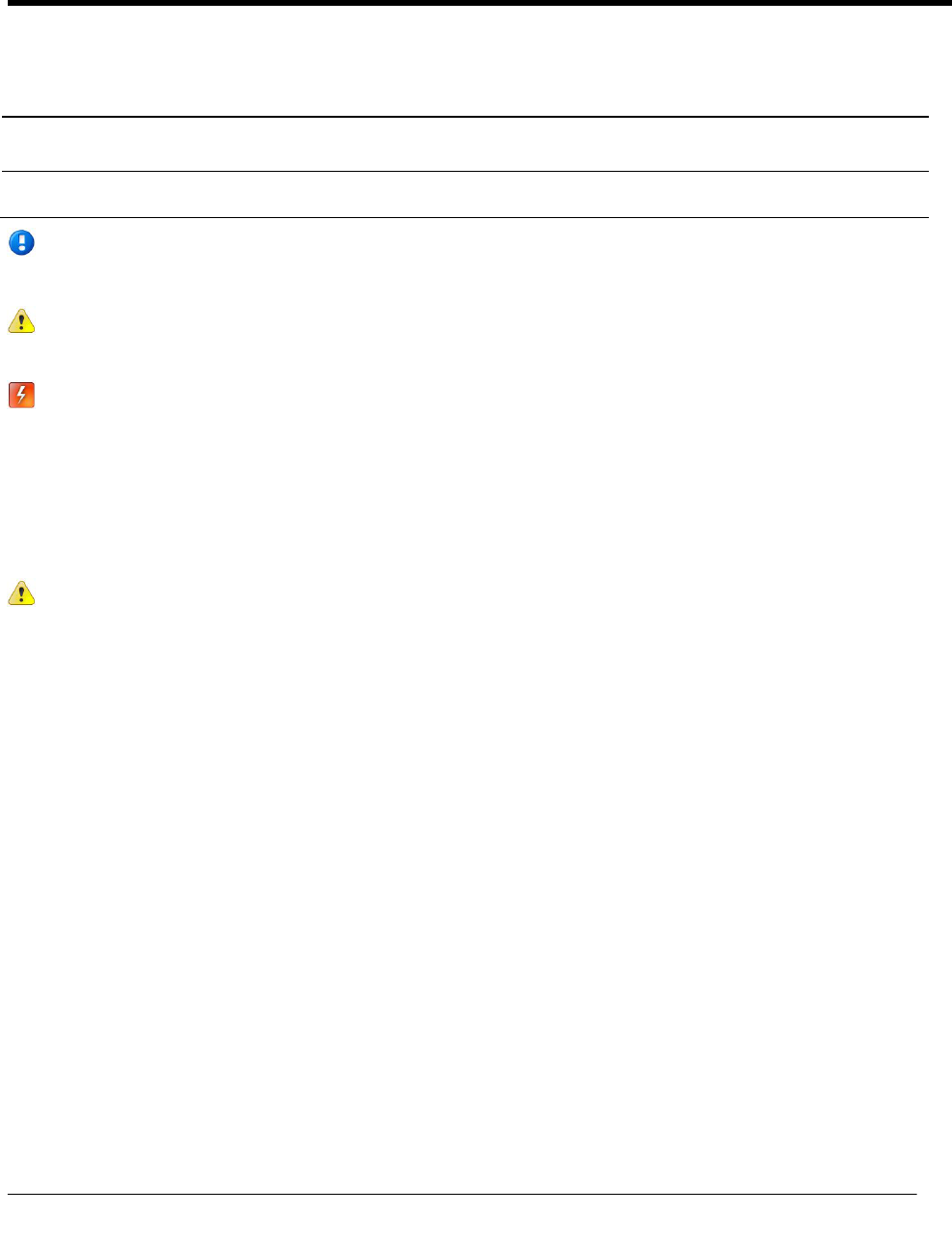
1. Fold the completed encoder/pulser wire connections into the endpoint housing where the instructions
PLACE GEL CAPS AND EXCESS WIRE IN THIS POCKET are stamped.
2. Route the register cable through the single backplate cutout.
3. Align the endpoint backplate with the mounting screw holes. Verify the Itron logo and arrow point up.
Installing the 100W-R and 100WP-R Endpoints
TDC-0951-001 100W-R and 100WP-R Datalogging Water Endpoint Installation Guide 12
Proprietary and Confidential
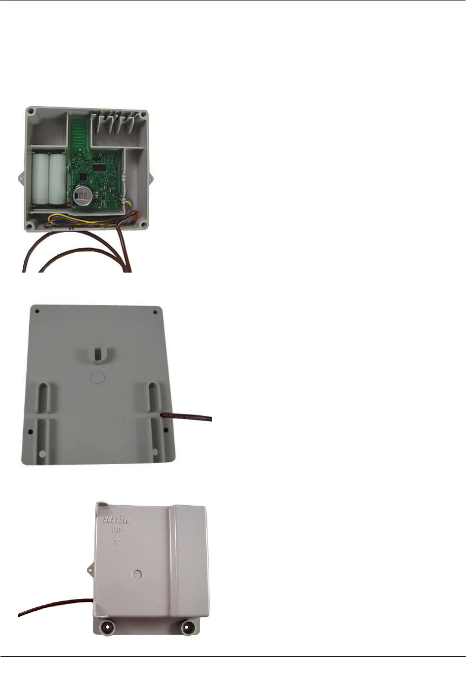
4. Insert a backplate mounting screw in one corner and tighten two to three turns. Insert the remaining three
screws, tightening a few turns.
5. Completely tighten all the screws in an alternating fashion.
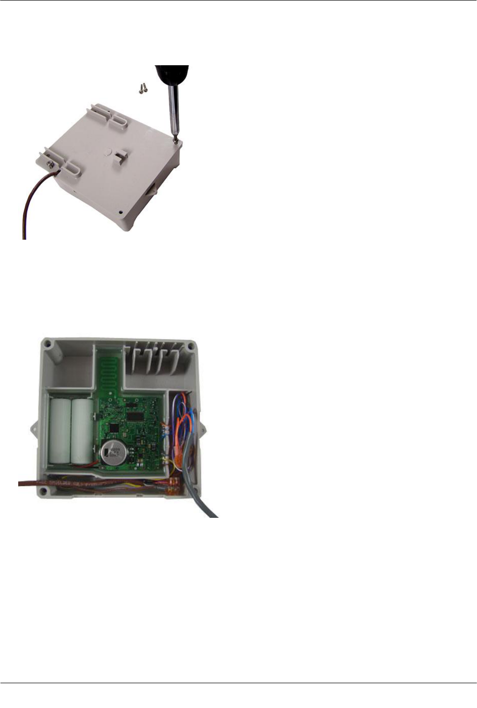
To attach an encoder/pulser and leak sensor backplate
1. Fold the completed encoder/pulser and Leak Sensor wire connections into the endpoint housing where the
instruction PLACE GEL CAPS AND EXCESS WIRE IN THIS POCKET is stamped.
Installing the 100W-R and 100WP-R Endpoints
TDC-0951-001 100W-R and 100WP-R Datalogging Water Endpoint Installation Guide 13
Proprietary and Confidential
2. Route the register cable through the appropriate backplate cutout and the Leak Sensor cable through the
remaining cutout.
3. Align the endpoint backplate with the mounting screw holes. Verify the Itron logo and arrow point up.
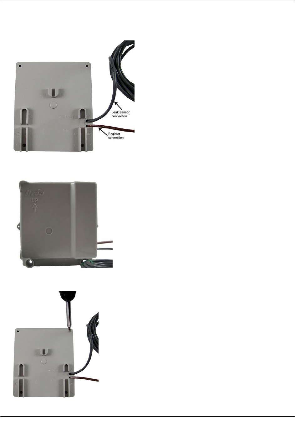
4. Insert a backplate mounting screw in one corner and tighten two to three turns. Insert the remaining three
screws, tightening a few turns.
5. Completely tighten all screws in an alternating fashion.
Installing the 100W-R and 100WP-R Endpoints
TDC-0951-001 100W-R and 100WP-R Datalogging Water Endpoint Installation Guide 14
Proprietary and Confidential
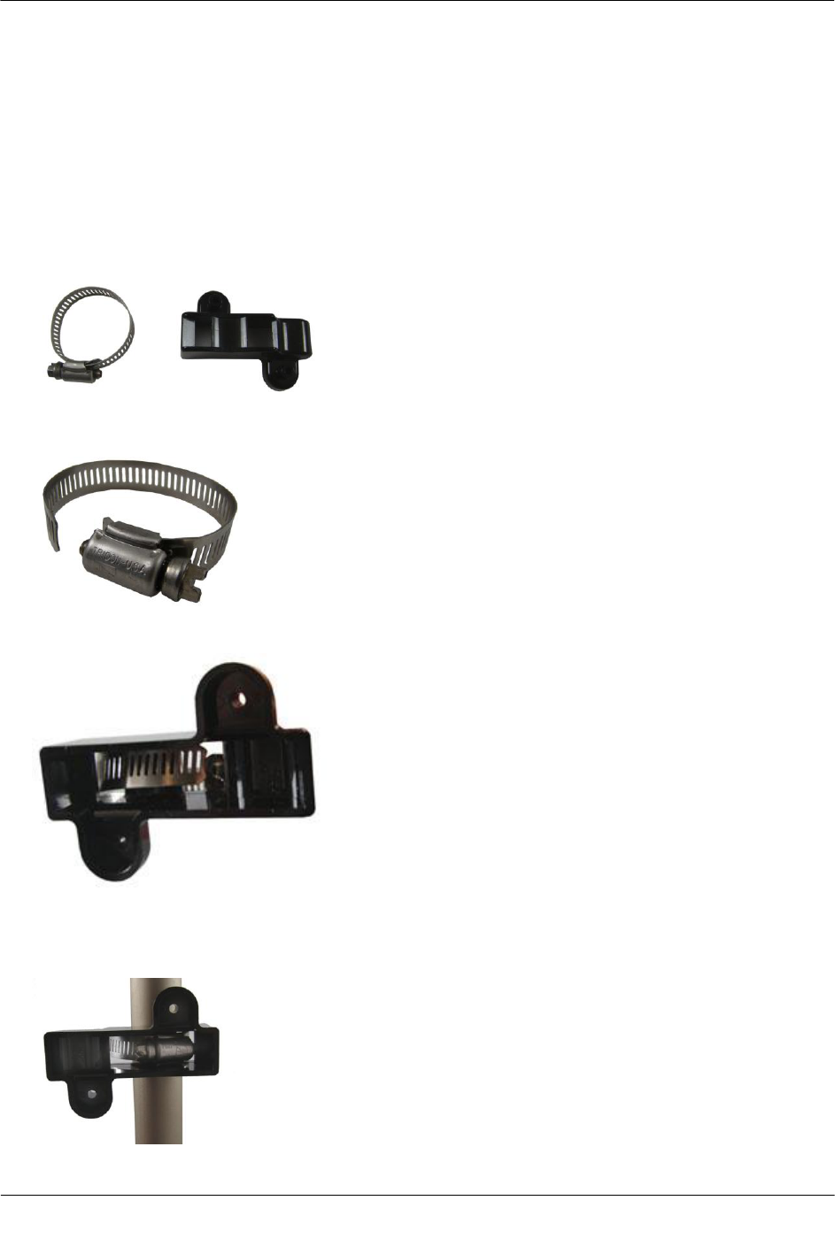
Pipe Mount Installation
The endpoint can mount on a pipe vertically, diagonally, or horizontally using a Pipe Mounting Kit and
Remote Mount Kit (see 100W-R and 100WP-R Accessories on page 10).
To mount the adapter plate on a vertical pipe
1. Take the pipe bracket and band clamp from the Pipe Mount Kit.
2. Loosen the clamp screw until the end of the band releases.
3. Push the end of the band through the hole in the pipe bracket.
4. Place the band clamp around the pipe. Push the end of the band through the hole in the band clamp and
into the entrance to the screw assembly. Tighten the band clamp until you can push the end of the band
into the hole in the pipe bracket.
Installing the 100W-R and 100WP-R Endpoints
TDC-0951-001 100W-R and 100WP-R Datalogging Water Endpoint Installation Guide 15
Proprietary and Confidential
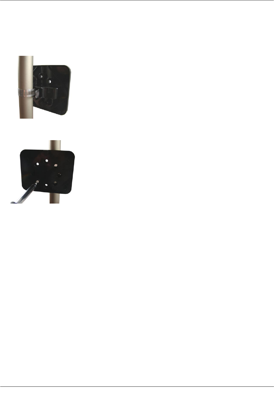
5. Tighten the clamp screw three or four more turns to make sure the end of the band does not pop back out
on this side of the pipe bracket. Verify the pipe clamp is in the final installation position on the pipe and
completely tighten the band clamp screw.
6. Place the adapter plate on the pipe bracket. The adapter-plate screw boss goes into the pipe-bracket recess.
7. Using the two shortest (1/2-inch) adapter-plate mounting screws from the Remote Mount Kit, connect the
adapter plate to the pipe bracket using the screw holes shown below.
8. Tighten both screws to 9 to 12 inch-pounds of torque.
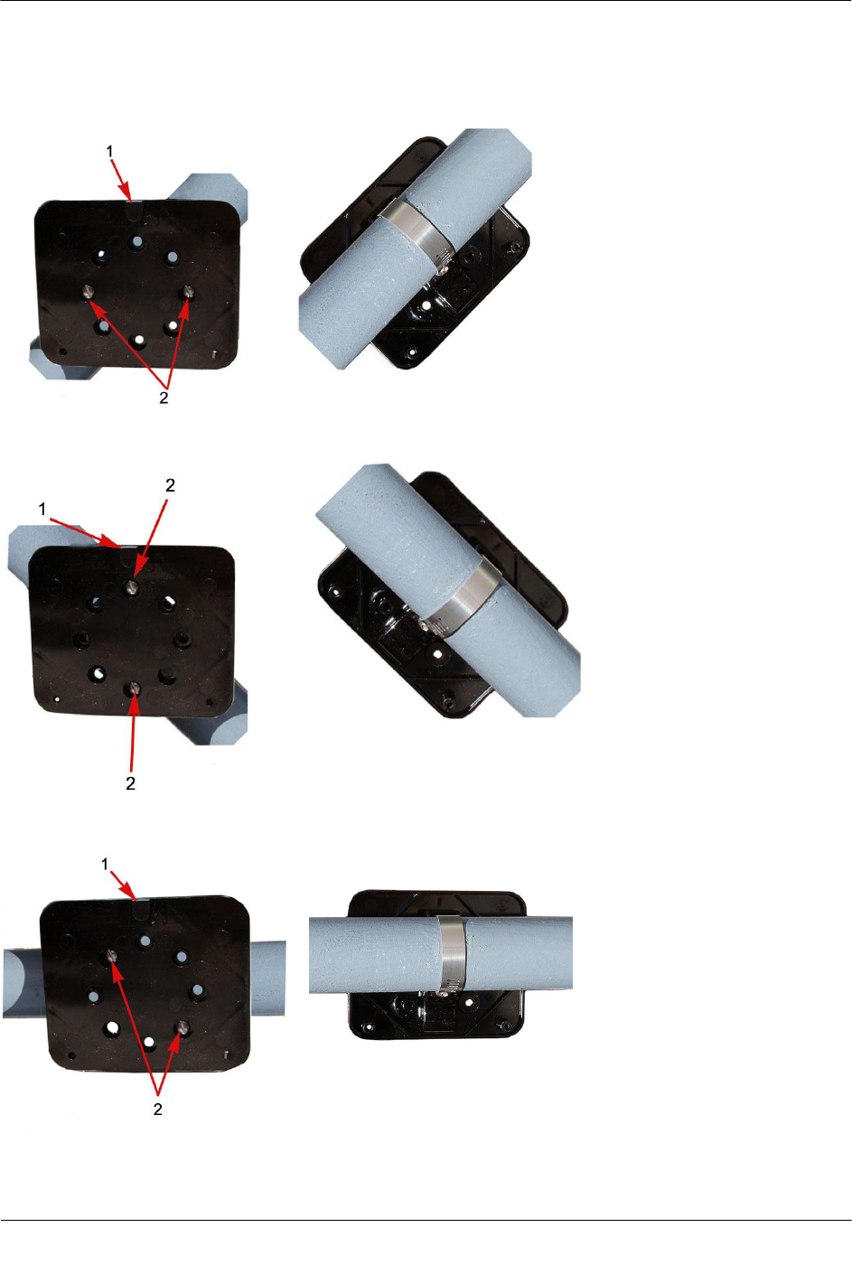
To mount the adapter plate in other positions
The installation procedure in the previous section shows how to mount the adapter plate on a vertical pipe.
The following pictures show the adapter plate on 45 degree angle and horizontal pipes. Regardless of the
angle of the pipe, the adapter plate mounting lug (1) must always be at the top.
Installing the 100W-R and 100WP-R Endpoints
TDC-0951-001 100W-R and 100WP-R Datalogging Water Endpoint Installation Guide 16
Proprietary and Confidential
If the pipe is at a 45 degree angle up to the right, install the adapter plate with the mounting screws (2) as
shown in the pictures below.
If the pipe is at a 45 degrees angle up to the left, install the adapter plate as shown in the pictures below.
If the pipe is horizontal, install the adapter plate as shown in the pictures below.