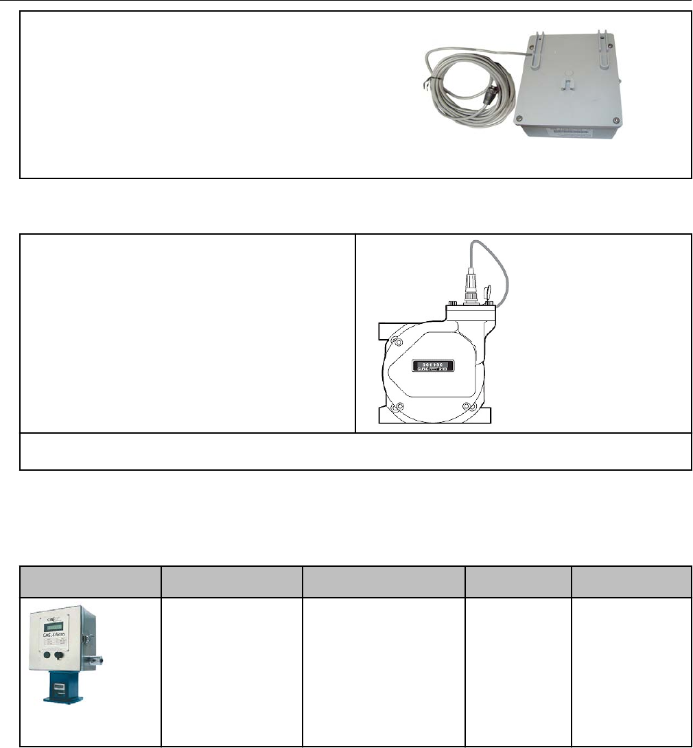
Itron 500GR AMR transceiver device for utility meters User Manual Installation Guide
Itron Inc AMR transceiver device for utility meters Installation Guide
Itron >
Users Manual

OpenWay® Riva™ 500G Gas ERT Module,
Remote Mount
Installation Guide
Technical
Communications
knowledge to shape your future
Identification
OpenWay Riva 500G Gas ERT Module Installation Guide, Remote Mount
01 May 2017
TDC-1678-000
Copyright
© 2017 Itron, Inc. All rights reserved.
Confidentiality Notice
The information contained herein is proprietary and confidential and is being provided
subject to the condition that (i) it be held in confidence except to the extent required
otherwise by law and (ii) it will be used only for the purposes described herein. Any third
party that is given access to this information shall be similarly bound in writing.
Trademark Notice
Itron is a registered trademark of Itron, Inc.
All other product names and logos in this documentation are used for identification purposes
only and may be trademarks or registered trademarks of their respective companies.
Suggestions
For more information about Itron or Itron products, see www.itron.com.
If you have questions or comments about the software or hardware product, contact Itron
Technical Support Services.
Contact
• Email: support@itron.com
• Internet: support.itron.com
• Telephone Itron Technical Support North America: 1-877-487-6602
For technical support contact information by region, go to www.itron.com and select your
country and language.

Contents
Chapter 1 Important Safety and Compliance Information.............................. 1
U.S. and Canadian patent numbers..................................................................................................................... 1
USA, FCC Part 15 Rules....................................................................................................................................... 1
ISED rules............................................................................................................................................................. 2
Transportation classication................................................................................................................................. 3
Modications, repairs, installation, and removal...................................................................................................3
Lithium battery safety........................................................................................................................................... 3
Equipment repairs.................................................................................................................................................4
Intrinsic safety.......................................................................................................................................................4
Electrostatic ignition hazard..................................................................................................................................4
ERT module cleaning............................................................................................................................................ 4
Drop height limitation............................................................................................................................................4
Chapter 2 About the OpenWay Riva Remote 500G Gas ERT Module............ 5
Transmission modes............................................................................................................................................. 5
Remote OpenWay Riva 500G gas ERT module and Itron Security Manager....................................................... 6
Enabling 500G ERT module security......................................................................................................... 7
Remote OpenWay Riva 500G gas ERT module functional specications............................................................7
OpenWay Riva 500G gas ERT module operational specications....................................................................... 7
Related documents...............................................................................................................................................8
Chapter 3 Mounting the Remote 500G ERT Module........................................ 9
Standard installation options................................................................................................................................ 9
Mounting the remote 500G ERT module on a pipe.............................................................................................. 9
Adapter plate mounting positions.......................................................................................................................11
Selecting a wall or at vertical mounting location.............................................................................................. 12
Chapter 4 500G Remote ERT Module Programming..................................... 14
Programming the remote ERT module............................................................................................................... 14
Itron programs and software variables............................................................................................................... 15
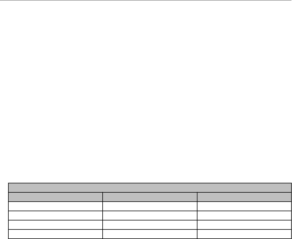
Chapter 5 Specific Meter Manufacturer Installation......................................19
Eagle Research meter installation.......................................................................................................................19
Eagle Research installation overview.......................................................................................................19
Eagle Research 500G product mounting instructions............................................................................. 20
Eagle Research mechanical and wiring installation instructions............................................................. 21
Connecting the 500G remote ERT module to the MPplus corrector................................................21
Connecting the 500G ERT module to the XARTU corrector.............................................................22
Eagle Research corrector programming and requirements notes........................................................... 23
Using Eagle Research Field Manager to change the MPplus settings.............................................24
Using Eagle Research Field Manager to change the XARTU corrector settings..............................26
Eagle Research programming note.................................................................................................. 27
Elster American meter installation...................................................................................................................... 27
Elster American 500G installation overview ............................................................................................27
Elster American meter 500G mounting instructions................................................................................ 28
OpenWay Riva 500G Gas ERT Module Installation Guide, Remote Mount TDC-1678-000 iii
Proprietary and Confidential
Elster American mechanical and wiring installation instructions............................................................. 29
Installing the remote module cable...................................................................................................31
Galvanic Gas Micro Installation.......................................................................................................................... 31
Galvanic installation overview.................................................................................................................. 31
Galvanic product mounting instructions.................................................................................................. 32
Galvanic mechanical and wiring installation instructions.........................................................................32
Programming the Galvanic Gas Micro electronic volume corrector........................................................ 32
GE Oil and Gas meter installation.......................................................................................................................32
GE Oil and Gas 500G installation overview............................................................................................. 33
GE Oil and Gas custom mounting options.............................................................................................. 34
GE Oil and Gas ES3 or ETC ordered with the AMR-ready mounting kit.......................................... 34
GE Oil and Gas IMC/W2, or MC2 with the GE mounting bracket kit............................................... 35
GE Oil and Gas mechanical and wiring installation instructions .............................................................36
D800/D1000 wiring and installation.................................................................................................. 37
GE Oil and Gas meters with pulse output wiring..............................................................................39
GE Oil and Gas meter programming and requirements notes ................................................................41
Honeywell Instrument 500G installation............................................................................................................. 43
Honeywell Instrument installation overview............................................................................................. 43
Honeywell product mounting instructions............................................................................................... 44
Honeywell mechanical and wiring installation instructions......................................................................45
Connecting the remote ERT modules to a Honeywell Mini-AT, Mini-Max, or EC-AT ...................... 45
Connecting the remote ERT module to the Honeywell TCI.............................................................. 47
Honeywell Instrument programming and requirements...........................................................................49
Honeywell software settings............................................................................................................. 49
Programming the Honeywell Instrument parameters....................................................................... 50
Itron meter installation........................................................................................................................................ 51
National meter installation.................................................................................................................................. 52
Romet meter installation..................................................................................................................................... 52
Romet installation overview..................................................................................................................... 53
Romet product mounting instructions..................................................................................................... 54
Romet mechanical and wiring installation instructions............................................................................54
Romet corrector programming and requirements notes..........................................................................58
Sensus meter installation....................................................................................................................................60
Sensus meter installation overview..........................................................................................................60
Sensus product mounting instructions.................................................................................................... 60
Sensus meter mechanical and wiring installation instructions................................................................ 62
Sensus meter programming and requirements notes .............................................................................62
Chapter 6 Diaphragm Meter Installation.........................................................63
Diaphragm meter installation overview...............................................................................................................63
Product mounting installation instructions......................................................................................................... 64
Diaphragm meter mechanical and wiring installation instructions..................................................................... 65
Remote ERT module programming and requirements notes............................................................................. 69
Appendix A Using gel-cap connectors to complete wiring connections.....71
Appendix B Optional sealant application instructions ..................................72
OpenWay Riva 500G Gas ERT Module Installation Guide, Remote Mount TDC-1678-000 iv
Proprietary and Confidential

Chapter 1 Important Safety and Compliance
Information
This section provides important information for your safety and product compliance.
U.S. and Canadian patent numbers
U.S. Patent numbers: 4,614,945; 4,753,169; 4,768,903; 4,799,059; 4,867,700
Canadian Patent numbers: 1,254,949; 1,267,936; 1,282,118
USA, FCC Part 15 Rules
This device complies with Part 15 of the FCC Rules. These limits are designed to provide
reasonable protection against harmful interference in a residential installation.
Operation is subject to the following two conditions:
• This device may not cause harmful interference.
• This device must accept any interference that may cause undesirable operation.
This device must be permanently mounted such that it retains a distance of 20 centimeters
(7.9 inches) from all persons in order to comply with FCC RF exposure levels.
USA, FCC Class B-Part 15
This equipment has been tested and found to comply with the limits for a Class B digital
device, pursuant to Part 15 of the FCC Rules. These limits are designed to provide
reasonable protection against harmful interference in a residential installation. This
equipment generates, uses, and can radiate radio frequency energy and, if not installed and
used in accordance with the instructions, may cause harmful interference to radio
communications. However, there is no guarantee that interference will not occur in a
particular installation. If this equipment does cause harmful interference to radio or television
reception, which can be determined by turning the equipment off and on, the user is
encouraged to try to correct the interference by one or more of the following measures:
• Reorient or relocate the receiving antenna.
• Increase the separation between the equipment and receiver.
• Connect the equipment into an outlet on a circuit different from that to which the receiver
is connected.
• Consult the dealer or an experienced radio or TV technician for help.
Compliance Statement Canada
This device complies with Innovation, Science
and Economic Development Canada (ISED)
license-exempt RSS standard(s). Operation is
Déclaration de Conformité
Le présent appareil est conforme aux CNR
d'Industrie Canada applicables aux appareils
radio exempts de licence. L'exploitation est
OpenWay Riva 500G Gas ERT Module Installation Guide, Remote Mount TDC-1678-000 1
Proprietary and Confidential

subject to the following two conditions: (1) this
device may not cause interference (2) this device
must accept any interference, including
interference that may cause undesired operation
of the device.
Under Innovation, Science and Economic
Development Canada (ISED) regulations, this
radio transmitter may only operate using an
antenna of a type and maximum (or lesser) gain
approved for the transmitter by Industry Canada.
To reduce potential radio interference to other
users, the antenna type and its gain should be so
chosen that the equivalent isotropically radiated
power (e.i.r.p.) is not more than that necessary
for successful communication.
autorisée aux deux conditions suivantes: (1)
l'appareil ne doit pas produire de brouillage, (2)
l'utilisateur de l'appareil doit accepter tout
brouillage radioélectrique subi, même si le
brouillage est susceptible d'en compromettre le
fonctionnement.
Conformément à la réglementation d'Industrie
Canada, le présent émetteur radio peut
fonctionner avec une antenne d'un type et d'un
gain maximal (ou inférieur) approuvé pour
l'émetteur par Industrie Canada. Dans le but de
réduire les risques de brouillage radioélectrique à
l'intention des autres utilisateurs, il faut choisir le
type d'antenne et son gain de sorte que la
puissance isotrope rayonnée équivalente (p.i.r.e.)
ne dépasse pas l'intensité nécessaire à
l'établissement d'une communication
satisfaisante.
Modifications and Repairs
To ensure system performance, this device and antenna shall not be changed or modified without
the expressed approval of Itron. Per FCC rules, unapproved modifications or operation beyond or in
conflict with these instructions for use could void the user's authority to operate the equipment.
ISED rules
Compliance Statement Canada Déclaration de Conformité
This device complies with Innovation, Science
and Economic Development Canada (ISED)
license-exempt RSS standard(s). Operation is
subject to the following two conditions: (1) this
device may not cause interference (2) this device
must accept any interference, including
interference that may cause undesired operation
of the device.
Under Innovation, Science and Economic
Development Canada (ISED) regulations, this
radio transmitter may only operate using an
antenna of a type and maximum (or lesser) gain
approved for the transmitter by Industry Canada.
To reduce potential radio interference to other
users, the antenna type and its gain should be so
chosen that the equivalent isotropically radiated
power (e.i.r.p.) is not more than that necessary
for successful communication.
Le présent appareil est conforme aux CNR
d'Industrie Canada applicables aux appareils
radio exempts de licence. L'exploitation est
autorisée aux deux conditions suivantes: (1)
l'appareil ne doit pas produire de brouillage, (2)
l'utilisateur de l'appareil doit accepter tout
brouillage radioélectrique subi, même si le
brouillage est susceptible d'en compromettre le
fonctionnement.
Conformément à la réglementation d'Industrie
Canada, le présent émetteur radio peut
fonctionner avec une antenne d'un type et d'un
gain maximal (ou inférieur) approuvé pour
l'émetteur par Industrie Canada. Dans le but de
réduire les risques de brouillage radioélectrique à
l'intention des autres utilisateurs, il faut choisir le
type d'antenne et son gain de sorte que la
puissance isotrope rayonnée équivalente (p.i.r.e.)
ne dépasse pas l'intensité nécessaire à
Important Safety and Compliance Information
OpenWay Riva 500G Gas ERT Module Installation Guide, Remote Mount TDC-1678-000 2
Proprietary and Confidential

Compliance Statement Canada Déclaration de Conformité
l'établissement d'une communication
satisfaisante.
Modifications and Repairs
To ensure system performance, this device and antenna shall not be changed or modified without
the expressed approval of Itron. Per FCC rules, unapproved modifications or operation beyond or in
conflict with these instructions for use could void the user's authority to operate the equipment.
Transportation classification
The Federal Aviation Administration prohibits operating transmitters and receivers on all
commercial aircraft. When powered, the 100G series remote ERT module is considered an
operating transmitter and receiver and cannot be shipped by air. All product returns must be
shipped by ground transportation.
Modifications, repairs, installation, and removal
To ensure system performance, this device and antenna shall not be changed or modified
without the expressed approval of Itron. Any unauthorized modification will void the user's
authority to operate the equipment.
In the event of malfunction, all repairs should be performed by Itron. It is the responsibility of
users requiring service to report the need for service to Itron.
Lithium battery safety
Warning: Follow these procedures to avoid injury to avoid injury to yourself or
others:
•The lithium battery may cause a fire or chemical burn if it is not disposed of
properly.
• Do not recharge, disassemble, heat above 100° Celsius (212° Fahrenheit),
crush, expose to water, or incinerate the lithium battery.
• Keep the lithium battery away from children.
• Fire, explosion, and severe burn hazard.
Important Safety and Compliance Information
OpenWay Riva 500G Gas ERT Module Installation Guide, Remote Mount TDC-1678-000 3
Proprietary and Confidential

Equipment repairs
Warning: Only authorized Itron personnel should attempt repairs on Itron
equipment. Attempts to do so by others might void any maintenance contract
with your company. Unauthorized service personnel might also be subject to
shock hazard on some Itron equipment if removal of protective covers is
attempted.
Intrinsic safety
Warning: Substitution of components may impair intrinsic safety.
Electrostatic ignition hazard
Warning: Electrostatic Ignition Hazard. Ensure area is not hazardous when
installing, servicing, cleaning, or touching the ERT module.
ERT module cleaning
Warning: Clean only with a damp cloth.
Drop height limitation
Warning: ERT modules contain sensitive electronic components which can be
damaged if the module is dropped from heights greater than 36 inches. Product
warranty coverage is contingent on not exceeding this drop height limitation.
Important Safety and Compliance Information
OpenWay Riva 500G Gas ERT Module Installation Guide, Remote Mount TDC-1678-000 4
Proprietary and Confidential

Chapter 2 About the OpenWay Riva Remote
500G Gas ERT Module
Itron remote 500G ERT modules are radio-frequency (RF) are IPv6 open standards based
gas modules designed to be read under Itron’s multi-purpose OpenWay Riva Network Mode
(RNM) or by legacy ChoiceConnect handheld, mobile and fixed network readers. In RNM,
the 500G gas ERT module offers firmware download, sub-hourly interval data, and
extended data storage. In 100 Series Mode, the ERT module operates identical to the 100G
DLS Dataglooging ERT module and can be ready by legacy ChoiceConnect handheld,
mobile, and network readers. The 500G gas ERT module continues Itron's tradition of
reliability, accuracy, and long battery life while meeting the industry's standards for security
and intrinsic safety.
The ERT module features tilt and cut cable-tamper reporting and security seals to indicate
physical tampering and minimize theft. Cut cable is reported when communications fail
between the meter or instrument and the ERT module, possibly from a cut or disconnected
cable. The ERT module circuitry senses an electrical current break to report a cut cable
tamper event.
Transmission modes
In Riva Network Mode, the module provides 3,840 buckets of interval data configurable from
1 minute to 1 hour (for example, 160 days of hourly data or 40 days of 15 minute data).
Interval options are 1-6, 10, 12, 15, 20, 30 or 60 minutes. Output power in RNM is +27 dBm
(500 milliwatts) and designed to transmit 4 times a day with a 20-year battery life
100G DLS Mode, the module provides 960 buckets of hourly interval data and can be set to
transmit in fixed network, mobile and handheld, hard to read mobile and handheld, or
cellular solutions mode (fixed network applications only).
•Fixed Network Mode. The remote 100G ERT module transmits a high-powered network
interval message (NIM) RF message every five minutes. Output power in this mode is
500 milliwatts or +27 dBm. Interspersed in the high power NIM, the remote 100G ERT
module transmits a medium power RF message at 10 milliwatts or +10 dBm every 60
seconds. In Fixed Network mode, the expected battery life is 20 years.
•Mobile High Power Mode. The remote 100G ERT module transmits a high-powered RF
message every 60 seconds. Output power in this mode is 250 milliwatts or +24dbm. In
Mobile High Power Mode, the expected battery life is 20 years.
•Mobile and Handheld Mode. The remote 100G ERT module transmits a medium-
powered RF message every 15 seconds. Output power in this mode is 10 milliwatts or
+10dBm. In Mobile and Handheld Mode, the expected battery life is 20 years.
•(Optional) Hard to Read Mobile and Handheld Mode. The remote 100G ERT module
transmits a high-powered RF message every 30 seconds. Output power in this mode is
250 milliwatts or +24dBm. In Hard to Read Mobile and Handheld Mode, the expected
OpenWay Riva 500G Gas ERT Module Installation Guide, Remote Mount TDC-1678-000 5
Proprietary and Confidential

battery life decreases to 15 years in this mode. The hard to read mobile and handheld
mode should only be used for exceptionally hard-to-read applications (such as meters
installed on roof tops or in sub-basements).
•Itron Cellular Solutions (ICS) Mode. The 100G DLS module is compatible with the Itron
Cellular Solution and can be programmed for optimum operation with FDM Endpoint
Tools Enhanced. In ICS mode, the 100G DLS transmits a high-powered RF network
interval message (NIM) every five minutes. Output power in this mode is 500 milliwatts or
+27 dBm. Interspersed in the high power NIM, the 100G transmits a medium power RF
message at 10 milliwatts or +10 dBm every 60 seconds. In ICS Mode, the expected
battery life is 20 years.
Note: ICS mode is for fixed network application only. ICS is optimized to work with the
ICS communications module in Itron’s electric meter. The 100G DLS must be in a full
security mode to work with ICS. This is not part of the ICS mode, but is a system level
requirement.
An FCC license is not required to read the 500G ERT modules.
Remote OpenWay Riva 500G gas ERT module and
Itron Security Manager
The 500G ERT module is a component of Itron's OpenWay Riva system. The OpenWay
Riva system enhanced security, provided by Itron Security Manager (ISM), applies to the RF
communications between the collection device and the ERT module.
There are two fundamental security processes used in the Itron Security Manager to ensure
system communication confidentiality and validity.
•Authentication. Authentication is the process of confirming that an artifact is genuine or
valid. Authentication in the ERT module is the process of verifying a request is from a
valid source and in its original form.
•Encryption. Encryption is the process of transforming information to make it unreadable
to anyone who does not have a valid security key. There are two types of encryption,
symmetric and asymmetric. Symmetric encryption uses a shared key to decrypt or
encrypt information. Asymmetric encryption uses a private key to encrypt and a public
key to decrypt. Data transmissions over the network are protected using AES-256
encryption.
As a component of the Itron Openway Riva solution, the 500G gas module supports the
security model found in the OpenWay solution for both reading and programming. If the ERT
modules are shipped without enhanced security enabled (ready to secure), the utility can—
at a later date—configure the modules for ISM enhanced security.
Note: Enabling or working with Itron ISM enhanced security requires FDM Endpoint Tools
Enhanced.
About the OpenWay Riva Remote 500G Gas ERT Module
OpenWay Riva 500G Gas ERT Module Installation Guide, Remote Mount TDC-1678-000 6
Proprietary and Confidential
Enabling 500G ERT module security
When 500G ERT modules ship from an Itron factory, each module contains utility factory
keys. The presence of these utility factory keys does not enable the enhanced security; the
installer enables the enhanced security at the time the ERT module is deployed or at a later
time using an Itron programming device, Field Deployment Manager Endpoint Tools
Enhanced, and programming commands. Initial key exchange commands are secured using
the utility factory keys. For more information about programming the 500G ERT module for
security, see the FDM Endpoint Tools Mobile Application Guide (TDC-0934).
Remote OpenWay Riva 500G gas ERT module
functional specifications
Functional specification Description
Power source Two "A" cell lithium batteries
Tamper detection Tilt and cut cable
FCC compliance Part 15 certified
Innovation, Science and Economic
Development Canada (ISED) compliance
RSS-247 certified
Intrinsically safe per Telemetering Equipment for use in Hazardous
Locations, for Cl I, Div 1, Gp D for Haz Loc,
Temp Code T2, -40°C ≤ Ta ≤ +70°C.
Product identification Numeric and bar coded ERT type and serial
number
Construction materials Gray polycarbonate housing and back plate with
encapsulated electronics
OpenWay Riva 500G gas ERT module operational
specifications
Operational specifications Description
Operating temperatures -40° to 158° F (-40° to +70° C)
Operating humidity 5 to 95 percent relative humidity
Program frequency 908 MHz
Transmit frequency Frequency hopping spread spectrum 903 to
926.85 MHz in the ISM band
Data integrity Verified in every data message
NIM message FM modulation; all other messages are AM
modulated
About the OpenWay Riva Remote 500G Gas ERT Module
OpenWay Riva 500G Gas ERT Module Installation Guide, Remote Mount TDC-1678-000 7
Proprietary and Confidential

Related documents
Document title Document part number
OpenWay Riva 500G Gas ERT Module Installation Guide,
Direct Mount
TDC-1671-XXX
OpenWay Collection Manager Operational Guidelines
OpenWay Riva Events and Exceptions Reference Guide
Gas and Telemetry Module Meter Compatibility List PUB-0117-002
Gas and Telemetry Module Ordering Guide PUB-0117-001
OpenWay Riva 500G Gas ERT Module Specification Sheet
Field Deployment Manager Endpoint Tools Mobile
Application Guide
TDC-0934-XXX
Field Deployment Manager Field Representative's Guide TDC-0936-XXX
Note The last three digits of the user and installation guides represent the document's
revision level. The revision level is subject to change without notice.
About the OpenWay Riva Remote 500G Gas ERT Module
OpenWay Riva 500G Gas ERT Module Installation Guide, Remote Mount TDC-1678-000 8
Proprietary and Confidential
Chapter 3 Mounting the Remote 500G ERT
Module
This chapter provides the instructions to mount the remote 500G ERT module on a pipe or
other flat vertical surface (wall).
Standard installation options
Mount the remote ERT module using the pipe mount or wall mount (flat vertical surface)
procedure.
•Pipe mount. Itron offers a pipe installation kit (CFG-0005-003) to mount the remote ERT
module on a pipe.
•Flat vertical (wall) mount. Installation using the wall mount option places the module on
a wall or other vertical surface.
Select the mounting option that will best work for your system. For example, your setup may
provide the location for a pipe mount but not a wall mount. The preferred mounting location
is near the meter or instrument, but some installations may require an extended cable
length. For example, your installation may require mounting the ERT module around a
corner to avoid RF interference. The remote ERT module supports cable lengths up to 300
feet with a recommended one-splice limitation. Installers must mount the remote ERT
module in a vertical position with the ERT label directional arrow pointed upward.
Warning: Do not mount the 500G remote ERT module in an orientation other
than vertical (remote ERT module label arrow pointed upward). Violating the
mounting orientation requirements may void the product warranty.
Caution: Upright vertical positioning is critical because:
• The 500G series modules are optimized for communication and require
upright mounting. Any other mounting position could result in reduced RF
performance.
• The remote module tilt tamper sensor requires upright mounting. Any other
mounting position can cause issues with the module's tilt tamper detection.
Mounting the remote 500G ERT module on a pipe
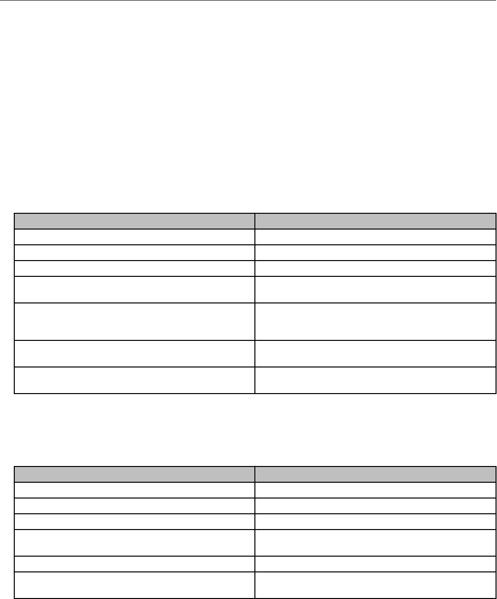
The following items are required to mount the remote ERT module on a pipe.
Itron part number Description
CFG-0005-003 Pipe mount kit contents:
OpenWay Riva 500G Gas ERT Module Installation Guide, Remote Mount TDC-1678-000 9
Proprietary and Confidential
Itron part number Description
2 band clamps, 2 tamper seals, pipe bracket, 2
cable ties, 1 adapter plate and the following
screws:
1. SCR-0215-001 (2) #8-16 x ½ inch slotted
pan-head tapping screw, corrosion-resistant
steel. Attaches the adapter plate to the pipe
bracket.
2. SCR-0215-002 (2) #8-16 1-inch slotted pan-
head tapping screw, corrosion-resistant steel.
Attaches the ERT module to the adapter
plate.
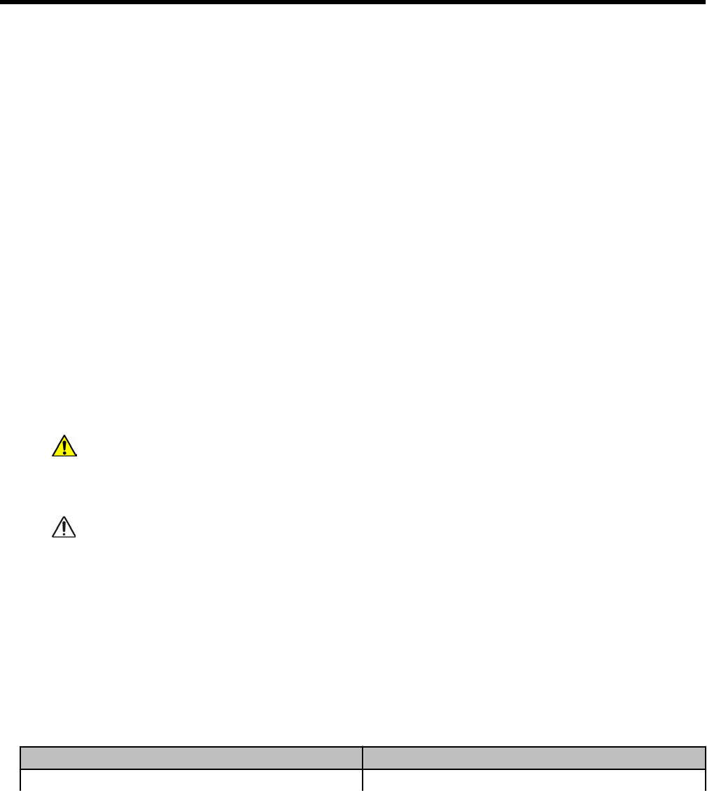
1. Remove the pipe bracket and clamp from the
kit.
2. Loosen the band clamp screw until the end of
the band releases.
3. Push the end of the clamp's band through the
holes in the pipe bracket as shown.
4. Place the band clamp around the pipe. The
band will loosely wrap around the pipe.
1. Push the end of the band through the band
clamp screw assembly.
2. Turn the band clamp's screw assembly to fit
into the pipe bracket opening.
3. Tighten the clamp screw until the band clamp
is secure on the pipe.
5. Place the adapter plate on the pipe bracket
with the mounting lug at the top. The adapter
plate screw bosses fit into the pipe bracket
recess.
Mounting the Remote 500G ERT Module
OpenWay Riva 500G Gas ERT Module Installation Guide, Remote Mount TDC-1678-000 10
Proprietary and Confidential
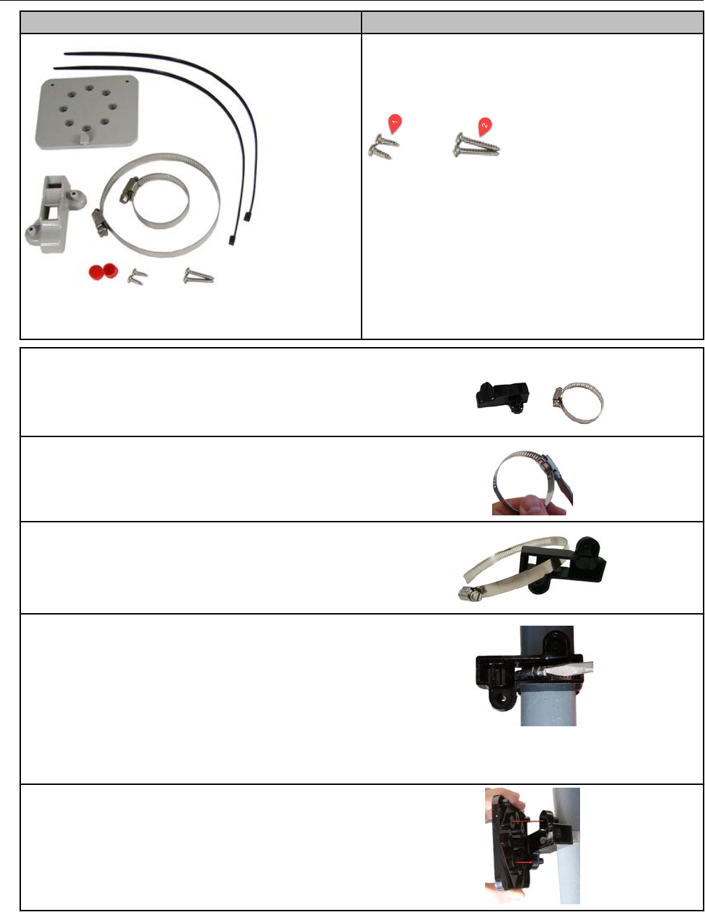
6. Ensure that the adapter plate is positioned as
shown with the mounting lug (1) at the top.
1. Install the adapter plate on the pipe mounting
bracket, use the two shortest (½-inch) screws
from the pipe mount kit.
2. Place the mounting screws into the holes as
shown (2).
Tighten both screws in an alternating pattern to 9
to 12 inch-pounds torque.
7. Position the back of the remote module
against the face of the adapter plate. The
adapter plate mounting lug (1) must be
positioned above the ERT module mounting lug
recess (2).
8. Push up on the module until the adapter plate
mounting lug (1) is as far as possible inside the
module mounting lug recess (2).
9. Align the ERT module back-plate mounting
holes with the pipe mount adapter plate holes.
Install the two one-inch ERT module mounting
screws from the installation kit. Tighten the
module mounting screws evenly in an alternating
pattern. Tighten the screws to 9 to 12 inch-
pounds torque.
10. Insert the tamper seals.
11. Gather the excess ERT module cabling into a
loop and use the cable tie to secure the gathered
cable to the pipe.
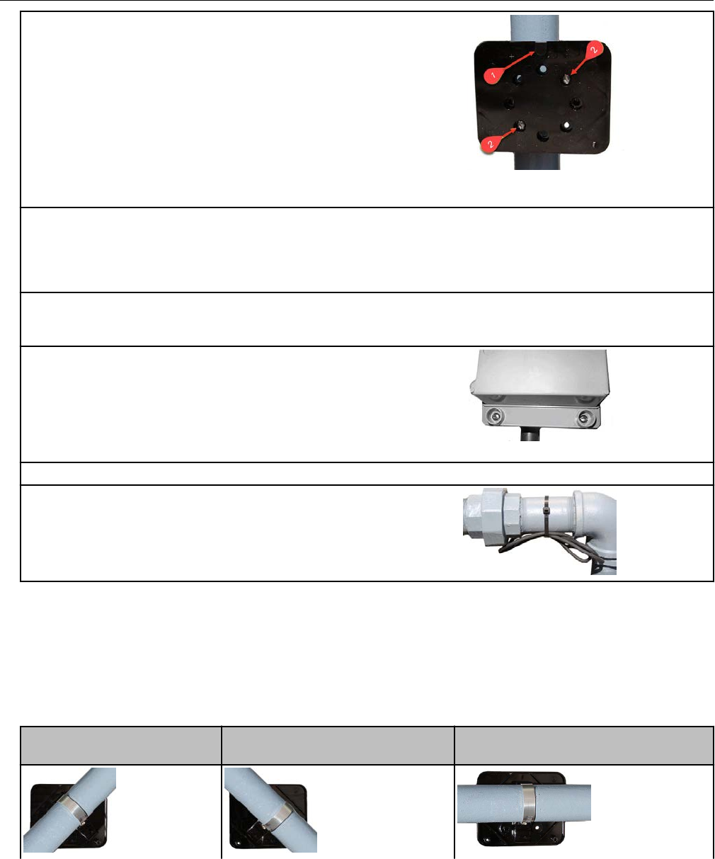
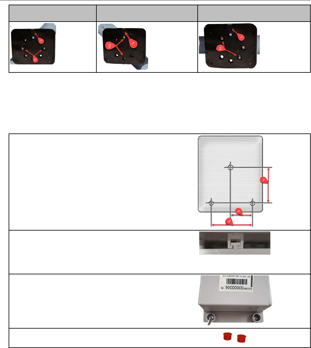
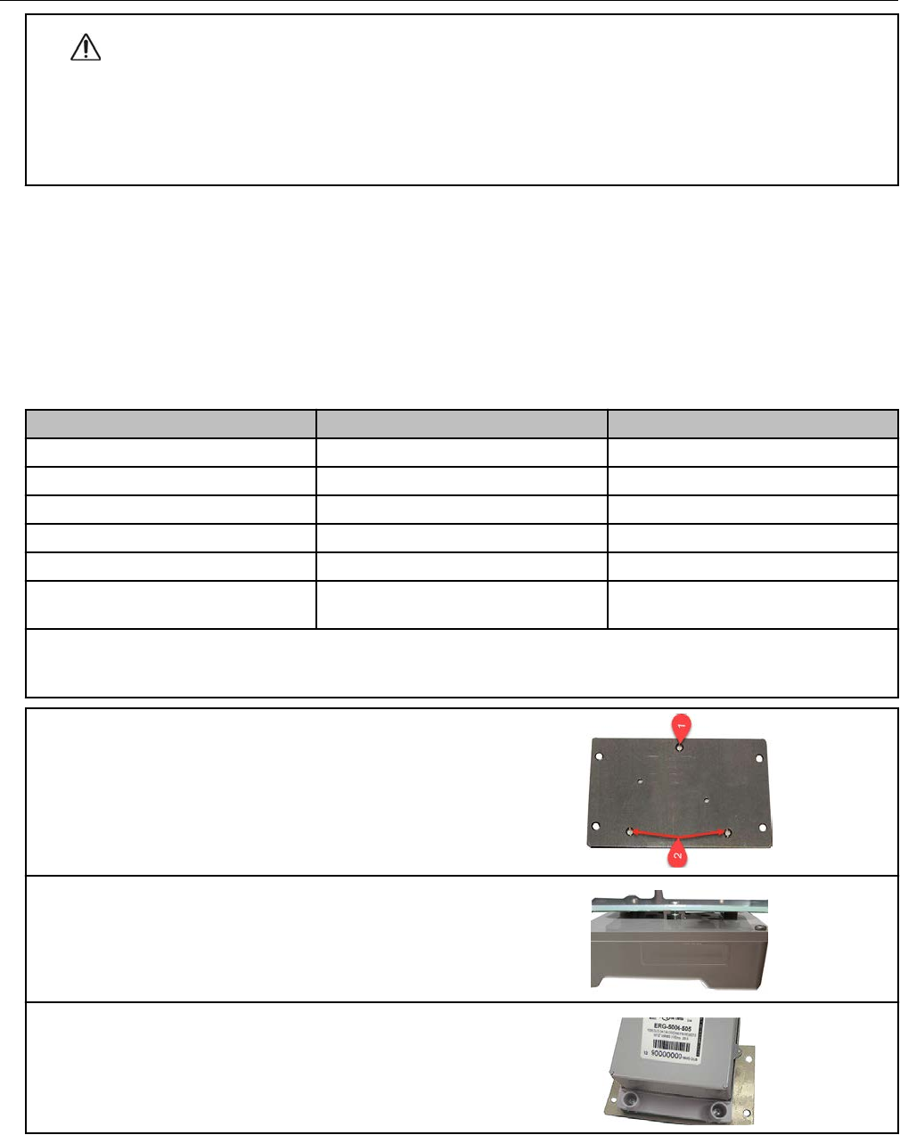
Adapter plate mounting positions
Note: The notch at the top of the adapter plate (1) must always be at the top position. The
following illustrations show the various mounting configurations. The adapter plate mounting
screw locations are indicated (2).
45-degree angle with the
pipe running to the right
45-degree angle with the pipe
running to the left
Horizontal
Mounting the Remote 500G ERT Module
OpenWay Riva 500G Gas ERT Module Installation Guide, Remote Mount TDC-1678-000 11
Proprietary and Confidential
45-degree angle with the
pipe running to the right
45-degree angle with the pipe
running to the left
Horizontal
Selecting a wall or flat vertical mounting location
Carefully select a mounting location free from electrical wires. The mounting location must
have the proper clearance to accommodate the 1-1/2-inch module mounting screws so
nothing is damaged by the drill or mounting screws. Use a compatible mounting screw.
1. Drill three pilot holes in the mounting surface.
The drilled pilot holes for the two bottom screws
must be on a horizontal line.
1. 3 inches
2. 1-11/16 inches
3. 3-3/8 inches
2. Screw the top mounting screw into the top pilot
hole drilled in step one, leaving enough of the
screw protruding so the ERT module lug recess
on the back plate slides over the screw head and
fits completely into the lug recess. Make
adjustments as necessary.
3. Install the two bottom mounting screws.
Tighten the screws in an alternating pattern to
secure the module firmly in position.
4. Place a new tamper seal over each bottom
ERT module mounting screw as required.
Mounting the Remote 500G ERT Module
OpenWay Riva 500G Gas ERT Module Installation Guide, Remote Mount TDC-1678-000 12
Proprietary and Confidential
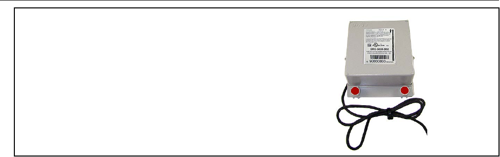
Note: To reduce the risk of cable damage,
secure any excess ERT module cabling with a
cable tie.
Mounting the Remote 500G ERT Module
OpenWay Riva 500G Gas ERT Module Installation Guide, Remote Mount TDC-1678-000 13
Proprietary and Confidential

Chapter 4 500G Remote ERT Module
Programming
Caution: You must program the 500G remote ERT module before use.
Programming Itron gas ERT modules requires an understanding of:
• Your meter's drive rate and the number of dials
◦ The drive rate and number of dials is important for programming the module to count
correctly and roll over to zero at the correct time. For example, a four-dial, 2 cubic-feet
meter configuration will count two cubic-feet for each rotation and roll over to zero after
9999.99 where the one's place is equivalent to 100 cubic-feet.
• How your system interprets the meter reading
◦ Some systems modify the consumption reading with the collection software. Other
times, the billing system is used to make modifications. If modifications are made in
both systems, issues may cause consumption reading errors.
It is important to understand your system before the gas ERT modules are programmed.
Program the 500G gas ERT module in RVM mode using a compatible programming device
loaded with FDM version 4.0 or higher.
Program the 500G gas ERT module in 100S mode using an approved programming device
loaded with Field Deployment Manager (FDM) software version 3.3 or higher.
To enable enhanced security and for more complete programming information, see the Field
Deployment Manager Endpoint Tools Mobile Application Guide (TDC-0934).
Programming the remote ERT module
Program the meter drive rate into the remote ERT module using a compatible programming
device.
1. Verify that you have the correct programming mode (RNM, fixed network mode, mobile high
power mode, mobile/handheld mode, or hard-to-read mobile/handheld mode) for your application.
2. For all programming and Check Endpoint operations using a handheld computer, hold the
handheld as close to vertical as possible. For best success, keep the handheld within six feet of the
target ERT module.
3. Programming parameters are based on the configuration file loaded into the programming
device.
Read or Check the remote ERT module using a handheld computer or Belt Clip Radio.
• If the read result is higher than the number programmed in step 1, the module is counting
correctly.
• If the read result is not higher than the number programmed in step 1, replace the remote ERT
module.
OpenWay Riva 500G Gas ERT Module Installation Guide, Remote Mount TDC-1678-000 14
Proprietary and Confidential

Itron programs and software variables
This section defines and clarifies possible system variables you may encounter in
programming Itron gas endpoints (ERT modules).
Field Deployment Manager (FDM)
The following tables illustrate various FDM programming configurations and the endpoint
response to each setting.
500G Remote ERT Module Programming
OpenWay Riva 500G Gas ERT Module Installation Guide, Remote Mount TDC-1678-000 15
Proprietary and Confidential
500G Remote ERT Module Programming
OpenWay Riva 500G Gas ERT Module Installation Guide, Remote Mount TDC-1678-000 16
Proprietary and Confidential
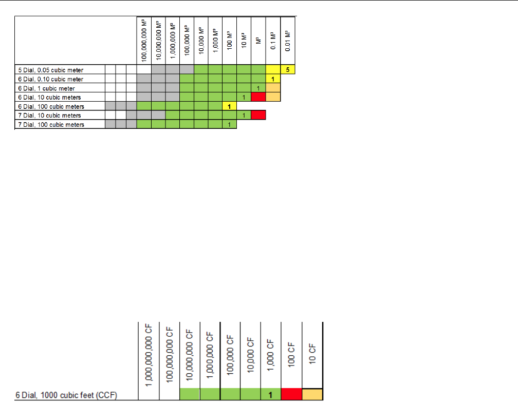
Programming example: Endpoint programmed for 6 dial, 1000 cubic feet.
1. Enter the initial index read. For this example, the initial read is 123456 where 6 = 600
cubic feet. After the initial programming, an endpoint read will result in a reading of
1234560 where the least significant digit is in 10's of cubic feet. Since counting is with a
drive rate of 1000 cubic feet and the reading is transmitted in 10's of cubic feet, the last
two digits of the reading will not change.
2. Program the endpoint to 123456.
3. Read the endpoint. The result should be 1234560 with the zero added to put the reading
in 10's of cubic feet.
4. Add one count. The result should be 1234660. Notice the last two digits of 60 do not
change.
Mercury X-Blank options
Endpoints (ERT modules) can be programmed with one of the Mercury X-Blank options.
There are 1, 2, 3, and 4 blank option available. Blank options are set up as a what-you-see-
is-what-you-get (WYSIWYG) configuration. The values are not set in cubic feet or cubic
meter standards. The Mercury X-Blank options are used in configurations where the system
receives pulses from a corrector or instrument that can change pulse values and has
configurable display digits. The Mercury-X Blank options allow users to program the
endpoint to match the configuration of the corrector or instrument.
Check Endpoint functions
The FDM Check Endpoint function triggers users to input the number of dials and drive rate
if a Check Endpoint is requested for an endpoint programmed for 5, 6, or 7-dial meter
configurations. The request to input the dial and drive rate information happens only if the
system has more than one option using the same count rate and rollover variable enabled in
their FDM business unit.
500G Remote ERT Module Programming
OpenWay Riva 500G Gas ERT Module Installation Guide, Remote Mount TDC-1678-000 17
Proprietary and Confidential

Note: Itron recommends that users only enable the configurations used by your business
unit. Having only one meter configuration option enabled (with the endpoint variable being
checked in the FDM business unit) eliminates the need to enter the number of dials.
Field Collection System (FCS)
In FCS, a Read Type Code can be assigned to a meter session. The Read Type Code in
conjunction with the Endpoint Type is used to determine how the endpoint reading is
formatted using the Endpoint Translation table in FCS. The Endpoint Translation table is a
configurable table that is used to determine the truncation factor and multiplier for each
reading. A default Endpoint Translation is defined for each type of endpoint supported by
FCS (ReadType of 00 for each EndpointType). If the default Endpoint Translation is not
formatting the read correctly, an additional Endpoint Translation can be defined to properly
format the read.
Since the Endpoint Translation Code is based on the Read Type Code and the Endpoint
Type, changing from a 40-series endpoint to a 100-series endpoint can cause the reading to
be truncated differently. If you are having issues with your reading after a change out, check
your Read Type Codes and Endpoint Translation Codes.
OpenWay Collection Engine
The OpenWay Collection Engine collects the raw reading and passes it on without making
any formatting changes.
Note: If Collection Engine is collecting an NIM, the NIM will contain leading digits that are
not read in the SCM or SCM Plus (see the FDM programming configurations table). This
may cause the need to make adjustments in the upstream systems.
Itron Enterprise Edition (IEE) Meter Data Management
The standard unit of measure (UOM) in IEE is cubic feet for gas endpoints. The reading
passed on by the gas endpoint is not in cubic feet if endpoints with 6 and 7-dial meter
configurations are programmed so adjustments are required to set the correct unit of
measure. If you are having issues with your readings in IEE but your endpoint and meter
index match, check your unit of measure within IEE.
If your reading is from the OpenWay Collection engine and there are issues with the rollover
of the reading, it may be an additional digit is not expected in the reading due to the NIM
message. The NIM Read format must be taken into account in upstream systems to perform
the proper read formatting.
500G Remote ERT Module Programming
OpenWay Riva 500G Gas ERT Module Installation Guide, Remote Mount TDC-1678-000 18
Proprietary and Confidential
Chapter 5 Specific Meter Manufacturer
Installation
This chapter provides the instructions to install the 500G remote ERT module to compatible
meters. Reference each section for compatible meters.
Eagle Research meter installation
This section provides the information to install the 500G remote ERT module on the
following compatible Eagle Research correctors.
Meter model Meter notes Module type Itron part number ERT module
notes
MPplus volume
corrector
Pulse width:
70mS and 500mS off
timing
Pulse output board
required
500G remote ERG-7000-502
XARTU-1 volume
corrector
Pulse width:
70mS on and 500mS off
timing
Corrector must have
Solid State relays
Eagle Research installation overview
Installing the 500G series remote ERT module to an Eagle Research volume corrector
involves four tasks.
1. Programming or verifying that the volume corrector is set up to work with the 500G
remote ERT module.
Programming requires a computer loaded with the Eagle Research Software and an
Eagle Research computer-to-volume corrector communication cable.
2. Connecting the ERT module to the volume corrector.
Requires a wire stripper and flat-tip screwdriver sized to tighten the terminal connections
on the Eagle corrector.
3. Mounting the remote ERT module. Select the mounting option appropriate for your
installation. Mounting options include:
OpenWay Riva 500G Gas ERT Module Installation Guide, Remote Mount TDC-1678-000 19
Proprietary and Confidential
• Wall mount on a sheet metal surface
• Pipe mount using the Itron pipe mount kit CFG-0005-003
• Custom Eagle Research mounting option using the Eagle research mounting rail
(Eagle Research part number 1010247)
Note: Itron recommends an optional sealant for installations where insect intrusion may
be a problem. For more information, see Optional sealant application instructions on
page 72.
4. Programming the 500G series remote ERT module. Programming requires an Itron ERT
programming device (for example, an FC300SR). For programming information, see
500G Remote ERT Module Programming on page 14
500G series module configuration with the meter is dependent on your system application.
See the Eagle Research meter product documentation for the Eagle Research Field
Manager database configuration information.
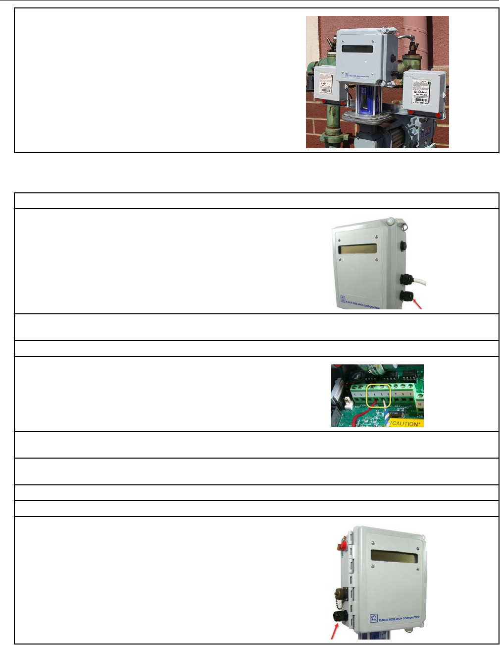
This mounting information describes installation for two 500G remote modules—one for
corrected reads and one for uncorrected reads. Installation is the same for both
configurations (corrected or uncorrected). Eagle Research meter outputs are optically
isolated from the meter control board and from each other. The volume corrector software
configuration controls the port operation. Follow the Eagle Research documentation and
these Itron instructions to ensure the correct compatibility and installation.
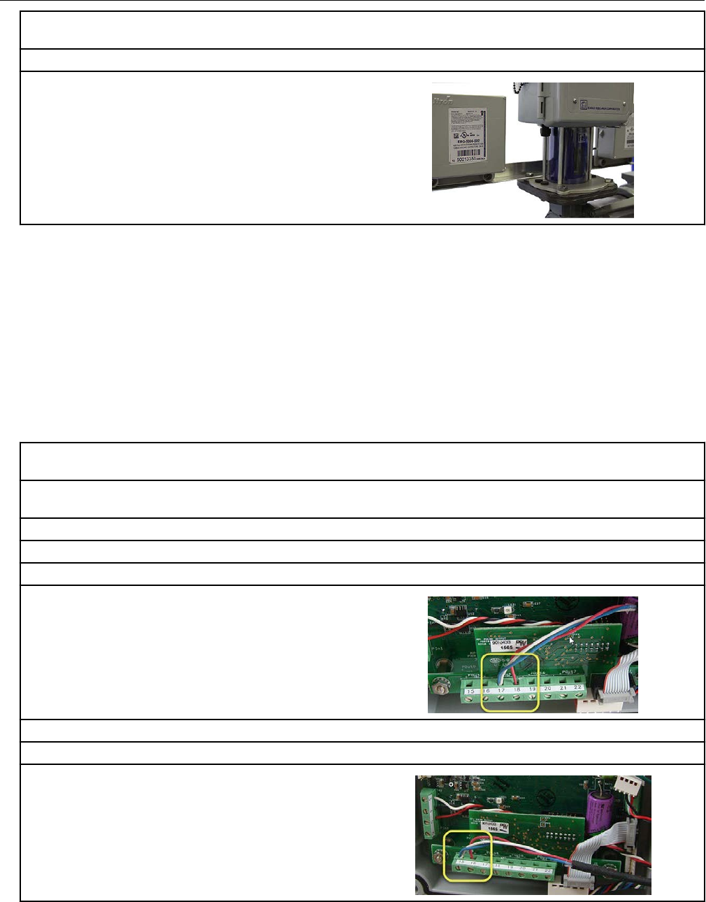
Eagle Research 500G product mounting instructions
Note: These instructions show the Eagle Research MPplus volume corrector. Installation is
the same for the XARTU-1 corrector.
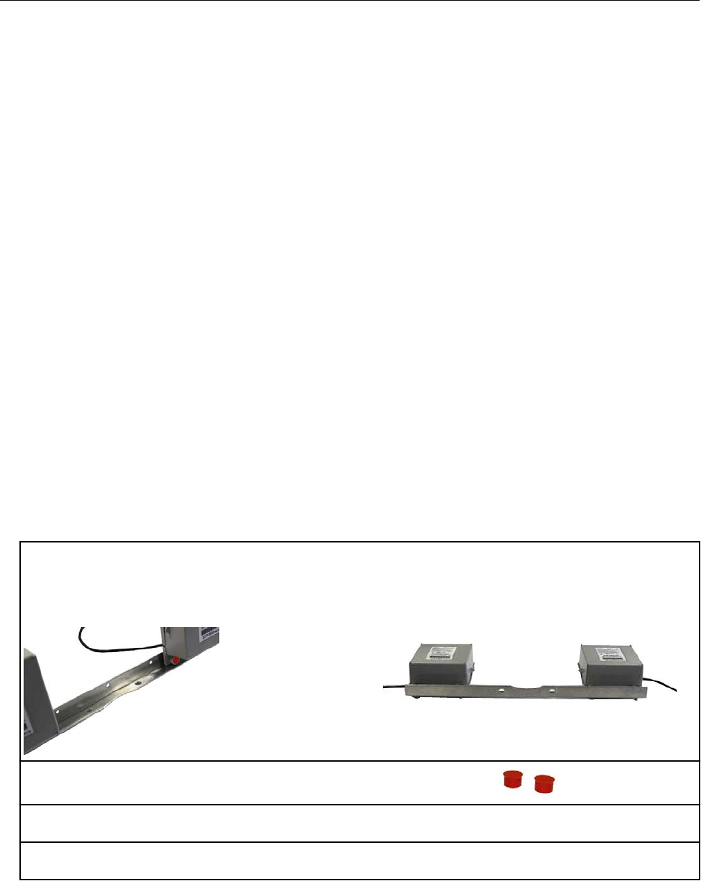
1. Mount a remote ERT module on each end of the mounting rail using the mounting screws
supplied with the ERT modules.
Note: The notch in the mounting rail is the front bottom of the rail. The ERT modules mount to the
back of the mounting rail.
2. Insert tamper seals into the tamper seal
mounting cups on the remote ERT modules.
3. With the corrector facing forward, align the corrector mounting holes with the index drive
mounting holes.
4. Insert the corrector's mounting screws in the front corrector and index mounting holes. Loosely
tighten the front two mounting screws.
Specific Meter Manufacturer Installation
OpenWay Riva 500G Gas ERT Module Installation Guide, Remote Mount TDC-1678-000 20
Proprietary and Confidential
5. Align the inside mounting rail screw holes over the back index and corrector mounting screw
holes.
6. Insert the two remaining mounting screws in the corrector bracket mounting holes.
7. Tighten all four mounting screws.
Eagle Research mechanical and wiring installation
instructions
This section provides wiring and connection information for compatible Eagle Research
products. Refer to the instruction for your product type.
Connecting the 500G remote ERT module to the MPplus
corrector
1. With the MPplus door open, insert the flying leads from the remote ERT module into the
compression connector on the left of the MPplus housing.
2. Pull the lead wires through the compression connector until there is adequate wire to reach the
terminal blocks labeled 15, 16, 17, 18, 19, 20, 21, and 22.
3. Tighten the compression connector.
4. Twist the remote ERT module's blue and white wires together.
For uncorrected reads:
5. Connect:
• the twisted blue and white wires to terminal 17
on the MPplus terminal block.
• the red remote ERT module wire to terminal
18 on the MPplus terminal block.
For corrected reads:
6. Connect the twisted blue and white wires to terminal 15 on the MPplus terminal block.
7. Connect the red remote ERT module wire to
terminal 16 on the MPplus terminal block.
Specific Meter Manufacturer Installation
OpenWay Riva 500G Gas ERT Module Installation Guide, Remote Mount TDC-1678-000 21
Proprietary and Confidential
8. Close and latch the MPplus corrector door.
Connecting the 500G ERT module to the XARTU corrector
For XARTU-1 uncorrected reads:
1. Insert the flying leads from the remote ERT
module into the compression connector on the
right of the XARTU-1 corrector housing.
2. Pull the lead wires through the compression connector until there is adequate wire to reach the
K2 terminal port.
3. Tighten the compression connector.
4. Connect the red remote ERT module wire to
pin 4 of the K2 terminal port.
5. Twist the remote ERT module's blue and white wires together and connect the twisted blue and
white wires to pin 5 of the K2 terminal port.
6. Plug the MTA battery connector from the battery pack into the VBAT1 connector to supply power
to the XARTU-1 corrector.
7. Close and latch the corrector door.
For XARTU-1 corrected reads:
8. With the XARTU door open, insert the flying
leads from the remote ERT module into the
compression connector on the left of the
corrector's housing.
Specific Meter Manufacturer Installation
OpenWay Riva 500G Gas ERT Module Installation Guide, Remote Mount TDC-1678-000 22
Proprietary and Confidential
9. Pull the lead wires through the compression
connector until there is adequate wire to reach
the K1 terminal port.
1. K1
2. K2
3. K3
10. Tighten the compression connector.
11. Connect the red remote ERT module wire to pin 1 on the K1 terminal port.
12. Twist the remote ERT module's blue and white wires together.
13. Connect the twisted blue and white wires to
terminal 2 on the K1 terminal port.
Eagle Research corrector programming and requirements
notes
Important: This information is subject to change without notice. Refer to the Eagle
Research product documentation to verify the most current programming and configuration
information for the 500G remote ERT module.
Using Itron 500G series remote ERT modules with Eagle Research volume correctors
requires Eagle Research Field Manager software configured with the parameters for your
model of Eagle Research corrector.
Specific Meter Manufacturer Installation
OpenWay Riva 500G Gas ERT Module Installation Guide, Remote Mount TDC-1678-000 23
Proprietary and Confidential
Using Eagle Research Field Manager to change the MPplus
settings
1. Open the Eagle Research Field Manager from
the Start menu or the desktop shortcut.
2. Connect the communications cable from your computer into the MS connector on the side of the
MPplus corrector. After the MS connector is connected, take note of the baud rate displayed on the
front of the corrector.
3. Click Connect on the upper left corner of the
Field Manager window.
A Connect to Remote window opens.
4. Select the following parameters:
•Connection Type: Direct
• Communications Port: enter your computer's port number
• Baud Rate: enter the baud rate that displayed in Step. 2.
5. Click OK.
6. Click View/Config.
Specific Meter Manufacturer Installation
OpenWay Riva 500G Gas ERT Module Installation Guide, Remote Mount TDC-1678-000 24
Proprietary and Confidential
The Field Manager window opens and displays
the settings for the current connection.
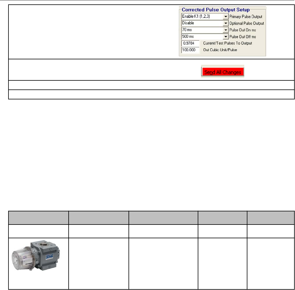
7. Click the Setup Parameters tab at the bottom of the parameters window. A parameters window
opens.
8. Enable POut 5 (17, 18) and set the additional
parameters as required in the Uncorrected
Pulse Output Setup at the lower right of the
window.
Important: If your software does not have an
option to use POut for the uncorrected pulse
output, contact Eagle Research to get the correct
software version.
9. Enter the parameters shown in the Corrected
Pulse Output Setup section in the lower left of
the window.
10. Click Send All Changes.
11. Verify that all parameters are correct.
12. Click Disconnect.
Specific Meter Manufacturer Installation
OpenWay Riva 500G Gas ERT Module Installation Guide, Remote Mount TDC-1678-000 25
Proprietary and Confidential
Using Eagle Research Field Manager to change the XARTU
corrector settings
1. Open the Eagle Research Field Manager from
the Start menu or the desktop shortcut.
2. Click Connect on the upper left corner of the
Field Manager window.
3. Select the following parameters:
•Connection Type: Direct
• Communications Port: Enter your computer's port number.
• Baud Rate: Enter the baud rate for the XARTU-1 corrector.
4. Verify that the time and station name are correct.
5. Click View/Config..
Click OK
6. Click the Setup Parameters tab at the bottom of the parameters window.
The Meter Setup and Accumulation Multipliers
window opens. Set up the meter and
accumulation multipliers as appropriate for your
installation.
7. Enable K2 (4, 5, 6) and set additional
parameters are required in the Uncorrected
Pulse Output Setup section in the lower right of
the window.
Specific Meter Manufacturer Installation
OpenWay Riva 500G Gas ERT Module Installation Guide, Remote Mount TDC-1678-000 26
Proprietary and Confidential
8. Set the Primary Pulse Output to Enable K1 (1,
2, 3) and the Optional Pulse Output to Disable
(unless it is used for another application) in the
Corrected Pulse Output Setup section in the
lower left of the window.
9. Click Send All Changes.
10. Verify that all parameters are completed and correct.
11. Click Disconnect.
Eagle Research programming note
During remote ERT module programming for use with the Eagle Research corrector, verify
that the module drive rate settings match those set in the corrector. For example, set the
ERT module drive rate for 1000 CF when the Eagle Research corrector drive rate is set for
1000 CF.
Elster American meter installation
Some meter manufacturers provide ERT mounting kits and installation procedures for their
meters. If the Elster American RPM meter to the remote ERT module installation
instructions are not available, follow the installation procedures in this section.
Meter model Meter notes Module type Itron part number ERT module
notes
10 Metric (10B) Originally manufactured
by Metric Metal Works
500G remote ERG-7000-501
Elster American RPM
Series rotary meter
Meter must have
factory-installed pulser
with connector output.
Purchase correct cable
interface from
manufacturer.
500G remote ERG-7000-503
Elster American 500G installation overview
Installing the 500G series remote ERT module to an Elster American meter involves four
tasks.
1. Programming or verifying that the meter is set up to work with the 500G remote ERT
module. Programming requires a computer communication cable.
2. Connecting the ERT module to the meter. Connecting the module to the meter requires:
• a wire stripper
• a flat-tip screwdriver
Specific Meter Manufacturer Installation
OpenWay Riva 500G Gas ERT Module Installation Guide, Remote Mount TDC-1678-000 27
Proprietary and Confidential
3. Mounting the remote ERT module (for mounting information, see Mounting the Remote
500G ERT Module on page 9. Select the mounting option appropriate for your
installation. Mounting options include:
• Wall mount on a sheet metal surface
• Pipe mount using the Itron pipe mount kit CFG-0005-003
• Custom Elster American meter mounting option
4. Programming the 500G series remote ERT module. For programming information, see
500G Remote ERT Module Programming on page 14. Programming requires an Itron
ERT programming device (for example, an FC300SR).
500G module configuration with the meter is dependent on your system application. See the
Elster American meter configuration information.
Elster American meter 500G mounting instructions
1. Remove the meter's top plate by removing the
two 5mm screws and carefully prying up on the
plate. The plate is secured with an O-ring seal.
Remove the O-ring from the plate.
Caution: If the O-ring is damaged
during removal, obtain a
replacement from Elster American
Meter Co.
2. Look into the meter tower and find the meter
switch lead and connector (4-pin).
3. If the lead and connector are not visible or
cannot be found, remove the four 5mm mounting
screws and the register cover. The meter switch
lead and connector will be visible inside the
cover.
Specific Meter Manufacturer Installation
OpenWay Riva 500G Gas ERT Module Installation Guide, Remote Mount TDC-1678-000 28
Proprietary and Confidential
4. Feed the lead and connector into the register
cover tower.
Note: Save any meter tags. You will re-install
them later in the installation process.
5. If you removed the register cover, replace the
cover using the four (4) 5mm mounting screws.
6. Attach the 4-pin male connector on the Elster American Meter adapter plate to the 4-pin female
connector inside the meter's tower. The connectors will slide together and latch.
7. Carefully push the connectors and wires into
the meter tower housing.
8. Lubricate the O-ring with O-ring lubricant and install the O-ring on the adapter plate. Insert the
adapter plate into the tower and tighten the two 5 mm screws.
Elster American mechanical and wiring installation
instructions
Caution: Do not use these meter drive rates to program residential direct-drive or
commercial direct-drive modules. Use the information in the following tables to
program ERT modules connected to GE Dresser rotary meters.
Note: Connection to an Elster American meter requires a cable interface compatible to an
Elster American RPM rotary meter.
Specific Meter Manufacturer Installation
OpenWay Riva 500G Gas ERT Module Installation Guide, Remote Mount TDC-1678-000 29
Proprietary and Confidential
1. Trim the ERT module wires to 3.5 inches.
2. Carefully strip the insulation covering from the meter cable (purchased from the meter
manufacturer) approximately 1-1/2-inches from the end.
Caution: Do not cut through the individual wire insulation.
3. Separate the meter cable's black, white, and red wires for connection to the remote ERT module.
Cut off the unused wires even with the outer covering (insulation).
Caution: Do not strip the individual wires.
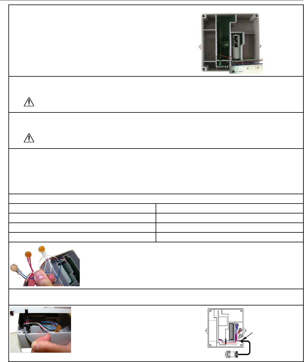
4. Connect the meter cable to the remote module wires using 3M gel-cap connectors following the
American RPM meter to remote ERT module wire connection information and wiring diagrams.
Important: Use a crimping tool compatible with gel-connectors. Do not use a standard pliers for
crimping gel-connects. For more information, see Using gel-cap connectors to complete wiring
connections on page 71.
Wire connection information
American meter wire Remote ERT module wire
Black Blue
White White
Red Red
5. Insert the meter cable through the slot on the ERT module backplate. Install a cable tie to the
meter cable wire below the meter cable insulation to provide strain relief.
Specific Meter Manufacturer Installation
OpenWay Riva 500G Gas ERT Module Installation Guide, Remote Mount TDC-1678-000 30
Proprietary and Confidential
6. Tuck the connectors and cable tie into the ERT
module housing. Place backplate on the
assembly and tighten the four backplate screws
using a size T-10 Torx screwdriver.
Important: Verify that the cable tie and gel
connectors are inside the module housing and
that the cable extends out of the slot in the
backplate. Torque the backplate mounting
screws to 9 to 12 inch-pounds.
Installing the remote module cable
1. Insert the plug on the cable connected to the
ERT module into the receptacle on the meter
adapter plate.
2. Tighten the threaded collar on the plug onto the American Meter interface receptacle. Verify the
connection is hand-tight.
Galvanic Gas Micro Installation
This section describes installation to Galvanic compatible correctors.
Meter model Meter notes Module type Itron part
number
ERT module notes
GasMicro Electronic
Volume Corrector
Must select 2 pulses/
second from pulse
output on the output
frequency menu.
500G remote ERG-7000-503 ERT module cut
cable requires
customer-supplied
cable capable of
terminating the
module white and
blue wires at the
meter interface.
Galvanic installation overview
Installing the 500G series remote ERT module to a Galvanic volume corrector involves four
tasks.
1. Programming or verifying that the volume corrector is set up to work with the 500G
remote ERT module. Programming requires a computer communication cable.
Specific Meter Manufacturer Installation
OpenWay Riva 500G Gas ERT Module Installation Guide, Remote Mount TDC-1678-000 31
Proprietary and Confidential
2. Connecting the ERT module to the volume corrector. Completing the connections
requires a wire stripper and flat-tip screwdriver sized to tighten the terminal connections
on the Galvanic corrector.
3. Mounting the remote ERT module. Select the mounting option appropriate for your
installation. See Mounting the Remote 500G ERT Module on page 9. Mounting options
include:
• Wall mount on a sheet metal surface
• Pipe mount using the Itron pipe mount kit CFG-0005-003
4. Programming the 500G series remote ERT module. For programming information, see
500G Remote ERT Module Programming on page 14. Programming requires an Itron
ERT programming device (for example, an FC300SR).
500G series module configuration with the meter is dependent on your system application.
See the Galvanic corrector product documentation for configuration information.
Galvanic product mounting instructions
Note: See the Galvanic product documentation for custom mounting instructions.
Galvanic mechanical and wiring installation instructions
GAS Micro wiring connections
GAS Micro corrector P13 connection 100G ERT module wires
Pulse output1-C C1 Blue/white
Pulse output1-E C2 Red
Pulse output2-E C3
Pulse output2-C C4
Programming the Galvanic Gas Micro electronic volume
corrector
For more information about programming the Galvanic Gas Micro Electronic volume
corrector, see the GAS MICRO Operator's Manual, Galvanic part number MA1956. Contact
Galvanic Applied Sciences, Inc to obtain the operator's manual.
GE Oil and Gas meter installation
This section provides the instructions to install the 500G remote ERT module on the
following compatible GE Oil and Gas meters.
Specific Meter Manufacturer Installation
OpenWay Riva 500G Gas ERT Module Installation Guide, Remote Mount TDC-1678-000 32
Proprietary and Confidential
Meter model Meter notes Module type Itron part
number
ERT module notes
D800/D1000
Pulse width must be set
greater than 100 ms.
Firmware version must
be 1.71 or higher.
500G remote ERG-7000-503
ERG-7000-505
Both modules are
compatible with
these meter models.
B3 Series pulse output
meter
LMMA pulse output
meter
Rotary meters equipped
with WeighandWire
solid state pulsers.
Meter must have
factory-installed pulser
with connector output.
Purchase correct cable
interface from GE
Dresser. Pulser must be
version 17 or higher.
500G remote ERG-7000-503
Integral Micro
Corrector IMC/W2
Integral Micro
Corrector MC2
Electronic volume
corrector for Series A
(LMMA) and Series B
(rotary meters). Must be
meter firmware version
1.94 or earlier. Pulse
width must be set for
125ms.
500G remote ERG-7000-505
Series 3 ES3 meter
Electronic
Temperature
Compensator (ETC)
Pulse width must be set
greater than 100ms.
Firmware version 1.71
or earlier.
500G remote ERG-7000-503
ERG-7000-505
Both ERT modules
are compatible with
this meter model.
GE Oil and Gas 500G installation overview
Installing the 500G remote ERT module to a GE Dresser meter involves the following tasks.
1. Programming or verifying that the meter is set up to work with the 500G remote ERT
module.
• Programming may require a computer and communication cable.
2. Wiring the GE-supplied cable to the ERT module or wiring the ERT module to the GE
device.
Specific Meter Manufacturer Installation
OpenWay Riva 500G Gas ERT Module Installation Guide, Remote Mount TDC-1678-000 33
Proprietary and Confidential
Wiring may require a wire stripper, flat-tip screwdriver, Torx T-15 screwdriver, and wire
crimper. Requirements are dependent on your installation.
3. If your installation uses a GE supplied cable, connect the cable to the meter. If your
installation requires wiring directly to the GE device, move to the next step.
4. Mounting the remote ERT module. For more information, see Mounting the Remote 500G
ERT Module on page 9. Select the mounting option appropriate for your installation.
• Wall mount on a sheet metal surface
• Pipe mount using the Itron pipe mount kit CFG-0005-003
• Custom GE Dresser mounting
◦ D800/D1000 mounting solution requires the following materials
■ (1) 8-32 x ½" screw
■ (2) 8-32 x ¾" screws
■ (3) 8-32" Kep® nuts
5. Programming the 500G remote ERT module. Programming requires an Itron
programming device (for example, an FC300SR). For programming information, see
500G Remote ERT Module Programming on page 14. 500G module configuration with
the meter is dependent on your system application. See the GE Dresser meter product
documentation for configuration information.
GE Oil and Gas custom mounting options
Specific product mounting instructions for GE D800/D1000 meters are included in the D800/
D1000 installation section.
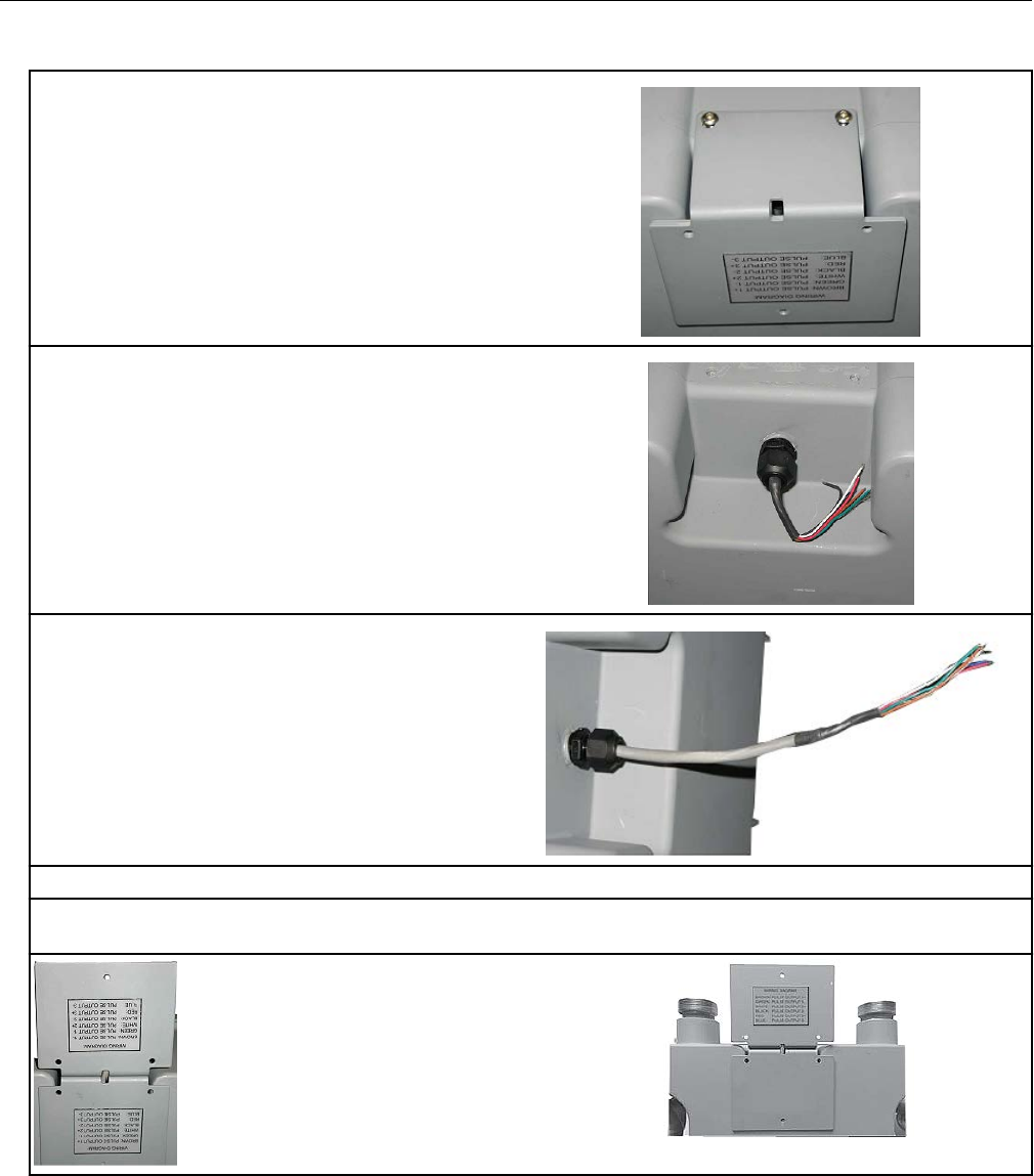
GE Oil and Gas ES3 or ETC ordered with the AMR-ready
mounting kit
1. Score (cut) the cable jacket surrounding the
ES3 or ETC wires and carefully remove the cable
jacket to expose the ES3 or ETC wires.
2. Connect the wires to the ERT module following the installation instructions in the GE Oil and Gas
meters with pulse output installation section.
3. Align the ERT module mounting holes with the
ES3 or ETC bracket mounting holes. Use a T15
Torx screwdriver to insert and tighten the
mounting screws. Tighten the screws in an
alternating pattern.
Specific Meter Manufacturer Installation
OpenWay Riva 500G Gas ERT Module Installation Guide, Remote Mount TDC-1678-000 34
Proprietary and Confidential
Caution: Upright vertical positioning is critical because:
• The 500G series modules are optimized for communication and require upright
mounting. Any other mounting position could result in reduced RF performance.
• The remote module tilt tamper sensor requires upright mounting. Any other
mounting position may cause issues with the module's tilt tamper detection.
GE Oil and Gas IMC/W2, or MC2 with the GE mounting bracket
kit
Note: This mounting option requires that you follow the installation instructions to attach the
meter maufacturer cable prior to completing this mounting option. This configuration
requires the GE mounting bracket kit available from GE Oil and Gas (GE part number
057783-000). The kit includes the listed materials.
Quantity Description GE Dresser part number
1 Mounting bracket 015951-000
1 Screw, 8-32 x 7/16-inch 000163-277
2 Screw, 8-32 x 3/4-inch 000163-282
3 Nut, 8-32 012829-005
4 Spacer, #10 053669-001
5 ERT module/bracket mounting
screw, M6 x 20 mm
013444-002
Important: The GE Oil and Gas mounting bracket kit does not include the cable required to
connect the remote module to the Amphenal connector on the IMC\W2.
1. Insert the 8-32 x 7/16-inch screw (1) into the
top of the mounting bracket. Insert the two 8-32 x
3/4-inch screws (2) into the bottom of the
mounting bracket.
2. Insert one 3/32-inch nut on the top 7/16-inch
bracket screw (A). Slide the 500G remote gas
module mounting lug over the top of the bracket
screw and nut.
3. Secure the bottom 500G remote gas module
mounting holes over the two 8-32 x 3/4-inch
screws with the remaining two 8-32 nuts.
Specific Meter Manufacturer Installation
OpenWay Riva 500G Gas ERT Module Installation Guide, Remote Mount TDC-1678-000 35
Proprietary and Confidential
4. Insert the #10 spacers into the four mounting
holes on the back of the IMC\W2.
Caution: Upright vertical positioning is very important because the remote module is:
• designed with the antenna in a vertical direction so the antenna is parallel to the
reading device (which has a vertical antenna). Matching antenna polarity can greatly
affect RF performance and enable easy ERT module reading.
• designed so the tilt tamper is vertical. It is important to maintain vertical positioning
in the field to enable tilt tamper stability.
• designed for installation with the batteries vertical (installed with the positive terminal
upward). Any other installation orientation will compromise battery life.
5. Secure the ERT module/bracket assembly on
the IMC\W2 using four ERT module/mounting
bracket screws (M6 x 20 mm). Install tamper
seals as required.
6. Connect the cable to the pulse output on the
IMC/W2 or MC2.
GE Oil and Gas mechanical and wiring installation
instructions
This section describes mechanical installation to the GE Oil and Gas meter and wiring
connections.
Specific Meter Manufacturer Installation
OpenWay Riva 500G Gas ERT Module Installation Guide, Remote Mount TDC-1678-000 36
Proprietary and Confidential
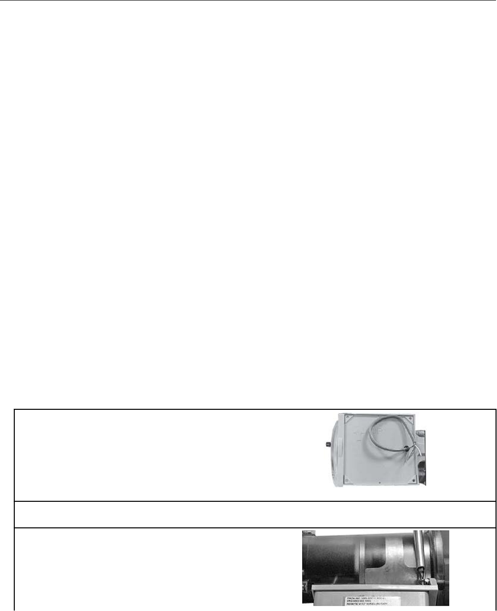
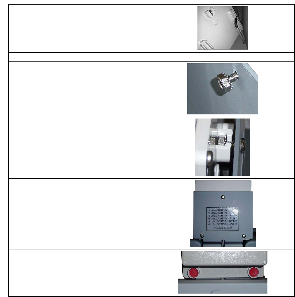
D800/D1000 wiring and installation
1. Loosen and remove the two screws holding
the mounting brackets to the meter.
2. After the brackets are removed, the pulse
output cable is visible.
3. Loosen the cable gland and pull the cable out
until it extends 7.5 to 8" out of the cable gland.
4. Tighten the cable gland. Do not use a pliers or wrench to tighten the cable gland.
5. Rotate one bracket. Route the meter cable through the holes located at the bend of the mounting
brackets.
Specific Meter Manufacturer Installation
OpenWay Riva 500G Gas ERT Module Installation Guide, Remote Mount TDC-1678-000 37
Proprietary and Confidential
6. Attach the brackets to the meter using the
previously removed screws.
7. Splice the meter pulse output wires to the ERT module wires using gel cap connectors. Follow
the wire connections for the D800/D1000 to 500G ERT module wire connections below.
Note: Use a crimping tool compatible with gel-connectors. Details on using the crimping tool are
included in the mounting installation section of this document.
D800/D1000 meter ERT module
Pulse output Wire Pulse output 1 Pulse output 2 Pulse output 1
with fault
Pulse output 2
with fault
Output 1+ Brown White and blue White
Output 1- Green Red Red
Output 2+ White White and blue White
Output 2- Black Red Red
Output 3+ Red White White
Output 3- Blue Blue Blue
8. Install a cable tie strain relief on the cable
approximately 1/8" from the end of the cable
insulation.
9. Position the cable so the strain relief is just
inside the slot on the module's backplate.
10. Carefully fold the ERT module wires into the
module's housing. Do not pinch the wires of gel
connections between the housing and the
backplate.
Specific Meter Manufacturer Installation
OpenWay Riva 500G Gas ERT Module Installation Guide, Remote Mount TDC-1678-000 38
Proprietary and Confidential
11. Install the four back plate screws using the
T-15 Torx screws supplied with the ERT module.
12. Route the cable through the channel in the backplate standoffs.
13. Insert the 8-32 x 1/2" screw into the top hole
in the meter mounting bracket and thread one of
the Kep nuts loosely onto the end of the screw.
14. Tilt the bottom of the ERT module away from
the mounting bracket and slide the notched
mounting hub onto the screw and Kep nut. Do
not tighten the screw.
15. Install the bottom two mounting screws and
Kep nuts. Tighten the three mounting screws in
an alternating pattern
16. Install the supplied red tamper seals over the
bottom mounting screws on the remote ERT
module.
GE Oil and Gas meters with pulse output wiring
These instructions describe B3 series, LMMA series, IMC, IMC/W2, MC2, and Series ES3
and ETC wiring connections. Installations are similar in their wiring of a meter manufacturer
cable to the ERT module that is then connected to the index or instrument.
Note: Wiring connections are different for the models as described. Use the connections for
your specific meter model.
Specific Meter Manufacturer Installation
OpenWay Riva 500G Gas ERT Module Installation Guide, Remote Mount TDC-1678-000 39
Proprietary and Confidential
1. Remove the backplate (4
screws) from the module and
expose the module lead wires.
The backplate and screws will
be re-installed on the ERT
module later in this procedure
so store them (temporarily) in a
safe, secure place.
2. Insert the lead wires from the
module and the correct GE
pulse output wire into new 3M
gel connectors (Itron part
number CON-0023-001) and
crimp using a 3M hand-held
crimping tool.
Note: Use a crimping tool compatible with gel-connectors. For information about crimping the
connections, see Using gel-cap connectors to complete wiring connections on page 71.
Important: The same process is used for wiring cables to the ERT module. Each meter or cable
may have different wire colors and wiring instructions. See the specific wiring configuration for your
product. Wiring configurations for the B3, LMMA, IMC/W2, MC2, ES3, and ETC meters with pulse
outputs are provided in the following information.
GE supplied cable that connects to a B3,
LMMA, IMC/W2, or MC2
ERT module
Blue Blue
White White
Red Red
Pulse output Wire Pulse output 1 only Pulse output with 1
fault
ES3 or ETC ERT module
Output 1+ White White and blue White
Output 1- Black Red Red
Output 3+ Red White
Output 3- Green Blue
Wiring for direct connection to the IMC/W2
To receive uncorrected reads: Connect the red
wire to terminal block 3 (TB3 telemetry output)
GND1 (ground) position (B). Connect the white
and blue wires to the pulse output 1 position (A).
Specific Meter Manufacturer Installation
OpenWay Riva 500G Gas ERT Module Installation Guide, Remote Mount TDC-1678-000 40
Proprietary and Confidential
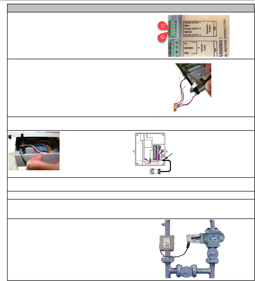
Wiring for direct connection to the IMC/W2
To receive corrected reads Connect the red
wire to the GND 2/3 (ground) TB3 telemetry
output position (C). Connect the white and blue
wires to the pulse output 2 position.
3. After completing the wiring connections, install
a cable tie to the meter cable just below the
exposed colored lead wires on the cable
insulation. Remove the excess cable tie using a
hand-held side-cutter pliers. The cable tie
performs as a cable strain relief to mitigate the
risk of destructive tension on the lead wires.
4. Tuck the three gel connectors and cable tie inside the module housing, as shown in the
placement illustration and schematic.
5. Install the 500G remote gas module backplate using the four screws previously removed from
the module and a Torx T-10 screwdriver.
6. Plug the cable into the pulse output of the index.
Important: Verify the cable tie and gel connectors are inside the module housing and the cable
extends out of the backplate slot. Torque the backplate mounting screws 9 to 12 inch-pounds.
7. Mount the module as required for your
application. Wall and pipe mount options are
described in Mounting the Remote 500G ERT
Module on page 9. Additional options for GE
specific mounting solutions are described in the
product specific mounting instructions in this GE
Oil and Gas section.
GE Oil and Gas meter programming and requirements
notes
GE MeterWare software is used to configure the ERT module's index settings.
Specific Meter Manufacturer Installation
OpenWay Riva 500G Gas ERT Module Installation Guide, Remote Mount TDC-1678-000 41
Proprietary and Confidential
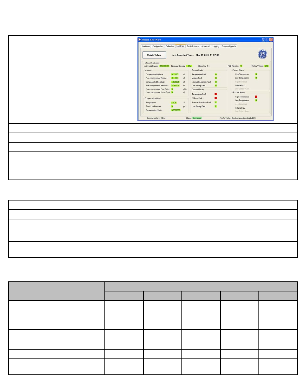
Important: This information is subject to change without notice. Refer to the GE MeterWare
product documentation to verify the most current information about programming and
configuring the corrector for use with the 500G remote ERT module.
1. Open the GE Dresser MeterWare
software to change the remote ERT
module settings.
2. Select the LiveData tab.
3. Confirm the firmware version and current index settings.
4. If you change a variable, click Update Values to complete the change.
5. Select the Configuration tab to view the volume configuration or confirm the volume configuration
and pulse settings. Use the drop-down lists to change the variable's setting.
Note: You must click OK to complete any setting changes.
Testing IMC or W2 communication with GE User Terminal (UT) communication
software
1. Connect the IMC/W2 to the PC using the serial cable.
2. Using the GE Dresser User Terminal (UT) communications software, connect to the IMC/W2.
Read the uncorrected or corrected count number on the remote ERT module with the Itron endpoint
reading device. Compare the IMC/W2 uncorrected or corrected amounts to those from the remote
ERT module.
4. Input approximately 20 pulses to the remote module. Verify the uncorrected or corrected counts
on the IMC/W2 and the remote module are the same.
Programming notes
The following table lists pulse rates for the pulse output of compatible GE indexes.
Index style
Meter size
8C-11M 16M 16M-56M 1.5-11M 16M-102M
B3 CTR index 10 100
B3 TC index
(Meter built 1/1999 and beyond)
10 100
B3 TC index
(Meter built prior to 1/1999
50 500
LMMA CTR index 10 100
LMMA TC or Series 3 CTR/TC
index
100 10
Specific Meter Manufacturer Installation
OpenWay Riva 500G Gas ERT Module Installation Guide, Remote Mount TDC-1678-000 42
Proprietary and Confidential
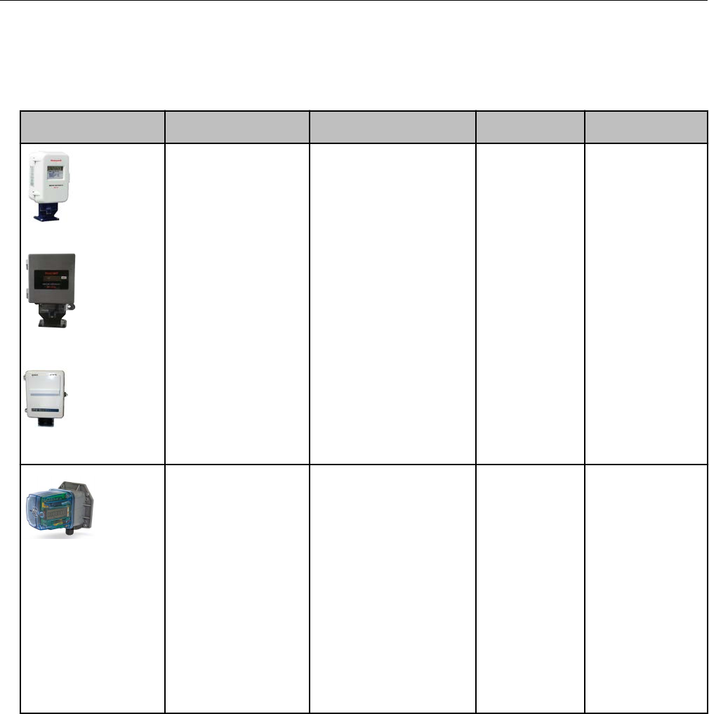
Honeywell Instrument 500G installation
This section provides the instructions to install the 500G remote ERT module on the
following compatible Honeywell Instruments.
Meter model Meter notes Module type Itron part
number
ERT module notes
Mini-AT
Mini-Max
EC-AT
Pressure and
temperature electronic
volume instruments.
Instruments must have
a Form A board, Form C
is NOT supported. Item
#56 Pulse Scaling
Factor must be 2.0. Item
#96 Cor Vol Display
must be 7, 6, 5, or 4
digits (1, 2, 3, or 4
blanks). Item #115
Output Pulse Code must
be set at 1, 2, or 4. For
connection to Mini-Max
only, Item #115 must be
set at 1 or 2. Item 124
wake up setting on
Honeywell corrector
must be set to 1.
Compatible corrector
firmware versions are
2.5020 and 2.73.
500G remote ERG-7000-502
TCI
Temperature
Compensating Index.
TCI must have a Form A
board, Form C is NOT
supported. Item #56
Pulse Scaling Factor
must be 2.0. Compatible
TCI firmware versions
are 1.06, 1,07, and
1.10.
500G remote ERG-7000-502
ERG-7000-503
The -502 module
has a 5' cable and is
used when longer
cabling is required.
This module will
return the cut cable
tamper.
The -503 module
has lead wires
designed for use
with the TCI
mounting bracket.
This module will
return the cut cable
tamper.
Honeywell Instrument installation overview
Installing the 500G series remote ERT module to a Honeywell Instrument involves four
tasks.
1. Programming the instrument and verifying that the Honeywell instrument is set up to work
with the 500G remote ERT module. Programming requires Honeywell software.
Reference Honeywell product and software documentation for the correct software and
version requirements.
Specific Meter Manufacturer Installation
OpenWay Riva 500G Gas ERT Module Installation Guide, Remote Mount TDC-1678-000 43
Proprietary and Confidential
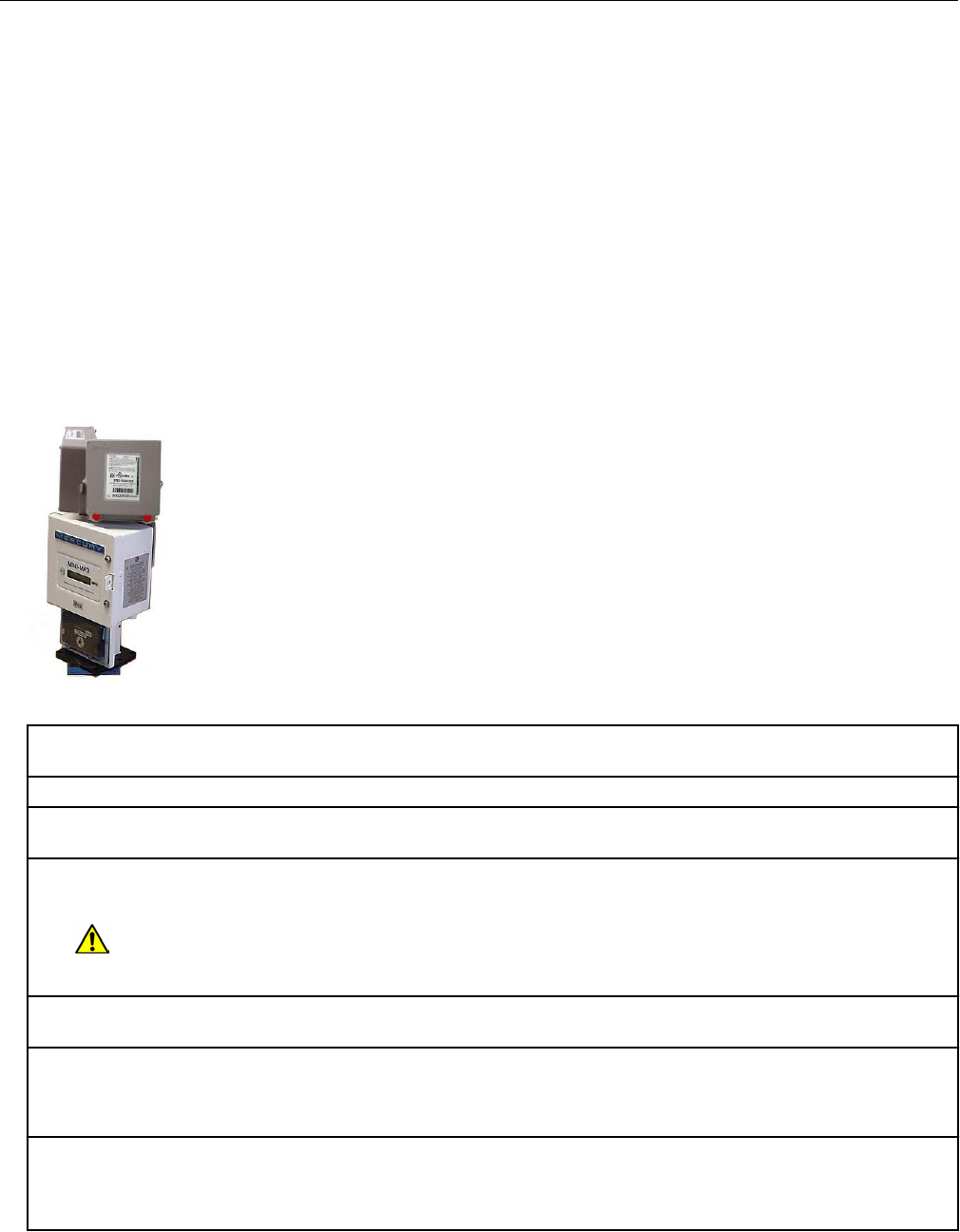
2. Installing the instrument and any required retrofit components.
3. Mounting the remote ERT module to a pipe or flat vertical surface. For more information,
(see Mounting the Remote 500G ERT Module on page 9).
1. Pipe mount using the Itron pipe mount kit CFG-0005-003.
2. Custom Honeywell mounting using Honeywell Kit 22-1077.
1. Custom mounting requires three #8-32 x ½-inch screws, 3 #8 metal flat washers,
and 3 rubber sealing washers.
4. Connecting the remote module to the instrument.
5. Programming the remote ERT module. For programming information, see 500G Remote
ERT Module Programming on page 14.
Honeywell product mounting instructions
Two remote ERT modules mounted on a Honeywell Mini-Max Instrument
1. Place the Honeywell Instrument volume corrector in shutdown condition and disconnect all
power from the Mini-Max main board.
2. Remove the battery pack from the volume corrector and set it aside.
3. Remove the four screws from the main board and the board from the enclosure. Set the board
aside.
4. Remove the two hex screws from the input switchboard and the switchboard from the enclosure
and set it aside. You will re-install the switchboard later.
Warning: The battery pack, main board and switchboard may be damaged if left in the
Honeywell Instrument volume corrector while completing this installation.
5. Drill two 3/16-inch holes in the back of the Mini-Max enclosure as specified by the information
included in the kit. Remove any metal shavings from the enclosure.
6. Clean the remote ERT modules with the alcohol wipe where you will place the corrected and
uncorrected labels (included in the kit).
Note: Clean the ERT modules with the alcohol wipe to ensure good label adhesion.
7. Mount the module for corrected pulse outputs on the left bracket mounting space. Insert three
#8-32 x 1/2-inch screws in a triangular pattern. Install the top screw so the head of the screw is
approximately 1/8-inch from the ERT mounting bracket surface. Slide the module onto the screw so
the mounting lug fits securely onto the screw. If necessary, remove the module and make any
Specific Meter Manufacturer Installation
OpenWay Riva 500G Gas ERT Module Installation Guide, Remote Mount TDC-1678-000 44
Proprietary and Confidential

necessary adjustment to the screw depth to ensure a secure fit. Install the two bottom screws in an
alternating fashion.
8. Mount the module for uncorrected pulse outputs on the right bracket mounting space. Insert
three #8-32 x 1/2-inch screws in a triangular pattern. Install the top screw so the head of the screw
is approximately 1/8-inch from the ERT mounting bracket surface. Slide the ERT module onto the
screw so the mounting lug fits securely onto the screw. If necessary, remove the module and make
any necessary adjustment to the screw depth to ensure a secure fit. Install the two bottom screws
in an alternating fashion.
9. Route the module cables under the bracket edge and toward the rear of the Honeywell
Instrument.
10. Mount the ERT mounting bracket (Honeywell Instrument part number 22-1077, included in the
kit) onto the Mini-Max enclosure. Place a #8 metal flat washer followed by a rubber sealing washer
onto both #8-32 x 3/8-inch screws. Align the lower threaded holes in the mounting bracket with the
drilled enclosure holes and insert a screw/washer through the enclosure housing. Screws heads
must be inside the enclosure. Tighten both screws using a screwdriver.
Note: Aligning the second bracket threaded hole and drilled hole may require some manipulation of
the mounting bracket.
11. Insert the module cables (both units) through the large cable strain relief on the left rear of the
instrument's enclosure. Leave a one-half to one inch drip loop under the cable strain relief.
12. Secure three cable ties on the module cables in three places on the cables as specified by
information included in the kit.
13. Re-install the input switchboard, main board, and battery pack removed in step 2.
Honeywell mechanical and wiring installation instructions
This section includes the information to wire two ERT modules to a single Honeywell
Instrument. Installation requires the correct programming parameters (for programming
parameters, see 500G Remote ERT Module Programming on page 14).
Connecting the remote ERT modules to a Honeywell Mini-AT,
Mini-Max, or EC-AT
With Itron 500G remote ERT modules, utilities can receive corrected and uncorrected
consumption values by installing two ERT modules. The ERT module for corrected reads is
attached to the corrector's pulse output. The ERT module for uncorrected reads is attached
to the input switch board. The corrected pulse output is programmable; the uncorrected
pulse output is dependent on the connected meter's drive rate.
Important: Some Honeywell Instruments have two pulse outputs so the uncorrected pulse
output could be connected to the additional output, but the connection should be to the input
switch board in case the corrector battery fails. Counts will be collected if the uncorrected
pulse is connected to the switch board since the board is not dependent on battery power.
This installation procedure requires a Honeywell mounting kit (Honeywell part number
22-1077). The illustrations show connection to a Honeywell Mini-AT. Connection to the
Honeywell EC-AT and Mini-AT are similar to these instructions. See Honeywell product
documentation for more information.
Specific Meter Manufacturer Installation
OpenWay Riva 500G Gas ERT Module Installation Guide, Remote Mount TDC-1678-000 45
Proprietary and Confidential
1. Connect the corrected module wires to TB1 on the Mini-Max board following the Corrected ERT
module connection information. Use Honeywell upgrade kit 40-2678-1 to provide the second pulse
output channel for the uncorrected endpoint.
2. Insert the remote ERT module cable into the instrument's compression connector.
3. Strip one inch of the outer insulation from the cable.
Warning: Keep wires away from the rotating magnetic spindle in the Honeywell
Instrument.
4. Strip ¼-inch individual wire insulation from the
red, white, and blue lead wires.
1. Count enabling wire (pulsed ground
reference)
2. Count sensing wire (high impedance positive
reference)
3. Cut cable sensing wire (positive return)
5. Twist the blue and white wires together and
connect them to the Honeywell Instrument
terminal strip connector (Phoenix connector)
following the Honeywell Instrument Item Code
Settings. For Item Code Settings, see
Programming the Honeywell Instrument
parameters on page 50.
Specific Meter Manufacturer Installation
OpenWay Riva 500G Gas ERT Module Installation Guide, Remote Mount TDC-1678-000 46
Proprietary and Confidential
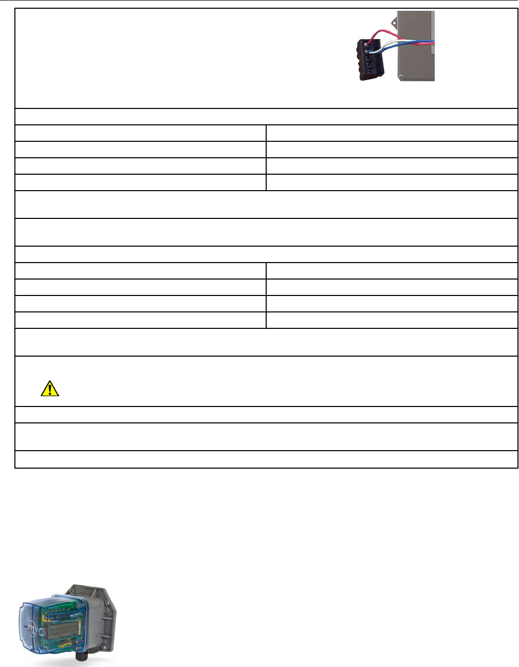
6. Connect the red wire following the Item Code
Settings. For Item Code Settings, see
Programming the Honeywell Instrument
parameters on page 50.
Note: In Honeywell Instrument EC-AT correctors,
the connector may be soldered to the pulse
board.
Corrected ERT module connections
Mini-Max TB1 ERT module wire color
K terminal Red
Ya terminal Blue*
Ya terminal White*
*Twist the blue and white ERT module wires together before connecting them to the Mini-Max
board. Tighten the terminal connection securely.
7. Connect the uncorrected module wires to the Input Switch Board UNC. VOL following the table
below.
Uncorrected ERT module connections
Mini-Max input switch board unc. vol. ERT module wire color
COM terminal Red
No terminal Blue*
No terminal White*
*Twist the blue and white ERT module wires together before connecting them to the Mini-Max
board. Tighten the terminal connection securely.
8. Tighten the large strain relief securely.
Warning: Do not crush the module through-cables when tightening the strain relief.
9. Re-install or reconnect the power or battery sources.
10. Close the instrument case and tighten the case screw securely. Replace any locks that were
removed for installation.
11. Install the remote ERT module. See Mounting the Remote 500G ERT Module on page 9.
Connecting the remote ERT module to the Honeywell TCI
The Honeywell Instruments Temperature Compensating Index (TCI) provides two Form-A
volume pulse outputs and one Form-B alarm output. These outputs are electronic switches.
The Form-A pulse outputs are configurable for compensated or uncompensated volume.
The Form-B output is for alarm output use only.
Specific Meter Manufacturer Installation
OpenWay Riva 500G Gas ERT Module Installation Guide, Remote Mount TDC-1678-000 47
Proprietary and Confidential
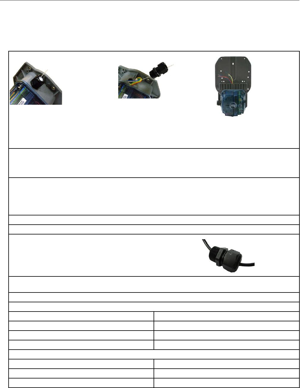
Connections to the three output pulse channels are completed using loose unterminated
wires (the individual wires from a cable) and gel-connectors. The TCI unit has six
unterminated wires that require six gel-connectors (Itron part number CON-0023-001) to
enable pulse connections to ancillary devices. Loose wires are located inside the gray
adapter plate behind the black strain relief fitting.
Strain relief fitting Honeywell TCI strain relief tether Backplate black fitting with
loose cable wires
(Honeywell part number
22-1929)
1. Connect the remote module to receive TCI pulse readings.
Note: Connect one ERT module/channel to the alarm output if the modules are used on channels A
and B.
2. Remove strain relief fitting by unscrewing it from the gray adapter plate.
Note: Do not remove the fitting's hex nut. Unscrew the entire fitting from the gray adapter plate. A
tether line is secured to the strain relief fitting. When the strain relief fitting is removed, the tether
line pulls the unterminated wires out of the adapter plate for access to the loose wires.
3. Loosen the strain relief fitting hex nut and remove the white plug from the center.
4. Place the strain relief fitting onto the field pulse cable.
5. If the field pulse cable is smaller than a 0.2-
inch diameter, install the rubber tube supplied
with the TCI onto the cable so the strain relief will
clamp onto the tube after it is reinstalled.
6. Connect the individual external pulse cable conductors to the unterminated wires following
Configuration for two ERT modules connected to one TCI.
Configuration for two ERT modules connected to one TCI
Channel A
TCI ERT module wire
Orange and brown White
Yellow Red
Blue (alarm) Blue
Channel B
TCI ERT module wire
White White
Green Red
Specific Meter Manufacturer Installation
OpenWay Riva 500G Gas ERT Module Installation Guide, Remote Mount TDC-1678-000 48
Proprietary and Confidential
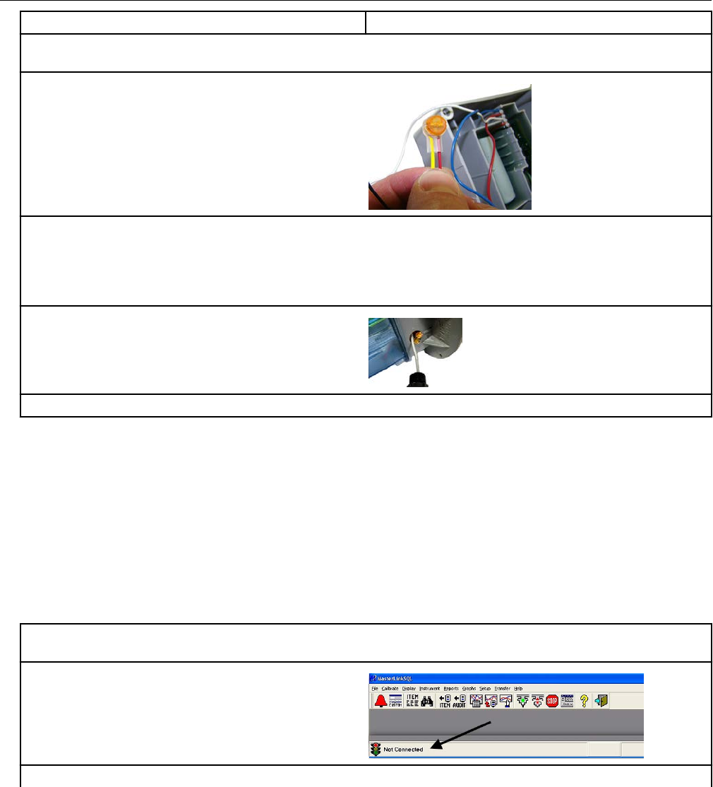
White Blue
7. Insert one unterminated wire into an opening of a gel-connector (six gel-connectors were
included with the TCI).
8. Insert the appropriate field cable wire into the
other gel-connector opening.
9. Verify both wires are fully inserted into the gel-connector prior to crimping.
Important: Use a crimping tool compatible with gel-connectors. Do not use a standard pliers for
crimping gel-connects. See Using gel-cap connectors to complete wiring connections on page
71.
10. Insert the gel-connected wires into the
threaded gray adapter plate hole.
11. Replace the strain relief and tighten until secure.
Honeywell Instrument programming and requirements
The Honeywell MasterLink SQL software is used to configure Honeywell products.
Important: This information is subject to change without notice. Refer to the Honeywell
MasterLink SQL product documentation to verify the most current information about
programming and configuring the corrector for use with the 500G remote ERT module.
Honeywell software settings
1. Connect the interface cable from the Honeywell instrument to a PC loaded with the MasterLink
SQL software.
2. Open the MasterLink SQL software. The
software opens and reports a "Not Connected"
status.
The Site List window automatically opens after the software detects an instrument.
Specific Meter Manufacturer Installation
OpenWay Riva 500G Gas ERT Module Installation Guide, Remote Mount TDC-1678-000 49
Proprietary and Confidential
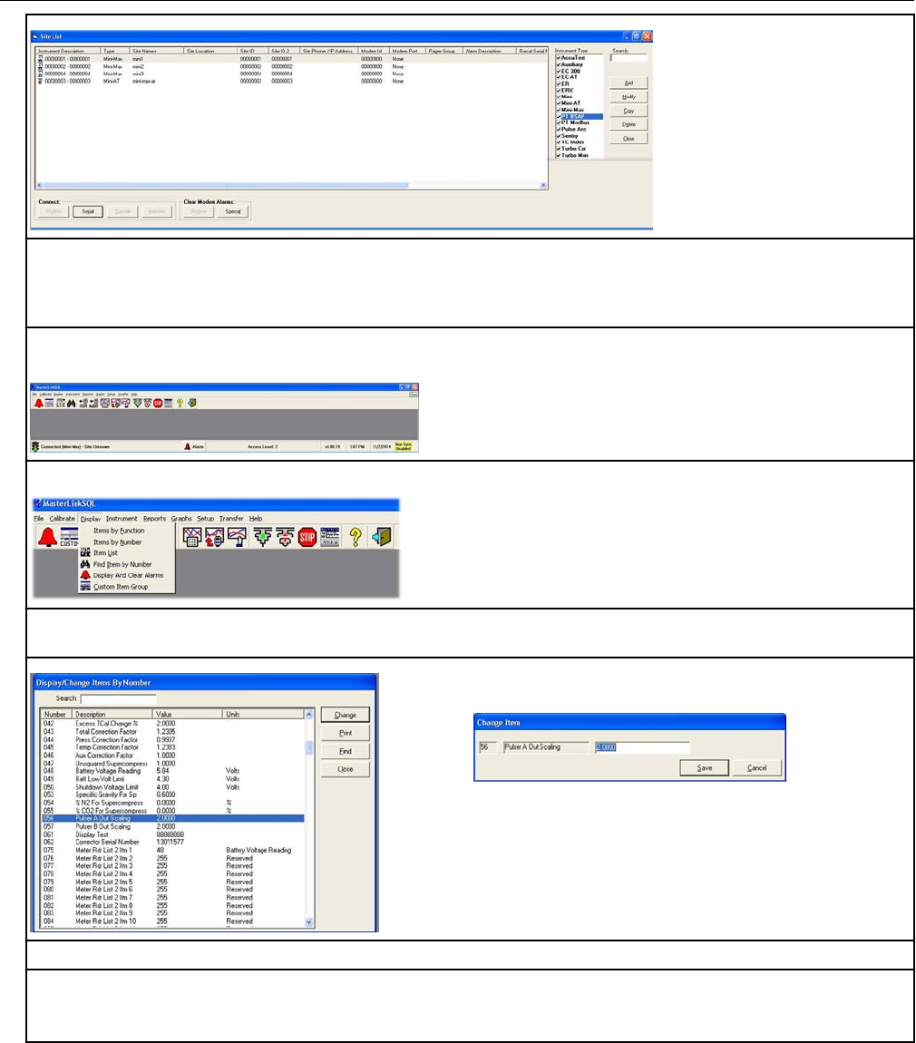
3. Select the Honeywell instrument type from the Instrument List on the right of the screen.
Important: You must select the correct instrument type. Selecting the incorrect type causes
communication errors.
4. The status indicator in the lower left corner of the MasterLink SQL software displays the
connection status as Connected (instrument type).
5. To view an Item configuration, select Display > Items by Number.
6. Verify the Honeywell instrument settings are correct. For example, Item number 56 must be set
to 2.0. If the setting is incorrect, click the Change button.
A Change Item pop-up provides the interface to
change the setting.
7. Enter the correct setting. Click Save.
8. Confirm that all settings match the settings required for the ERT module connected to the
Honeywell Instrument. For more information, see compatible ERT modules listed in Honeywell
Instrument 500G installation on page 43.
Programming the Honeywell Instrument parameters
Program the Honeywell Instrument parameters following these Item Code Settings.
Specific Meter Manufacturer Installation
OpenWay Riva 500G Gas ERT Module Installation Guide, Remote Mount TDC-1678-000 50
Proprietary and Confidential
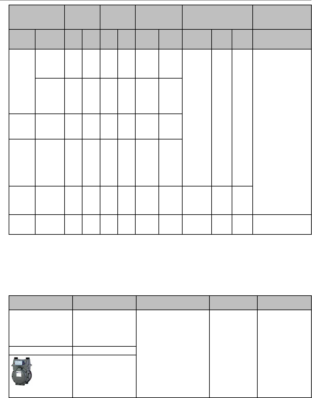
Channel A
Corrected
Volume
Channel B
Uncorrected
Volume
Channel C Pulse Output Spacing
Instru-
ment
Pulse
Output
Options
#56 #93 #57 #94 #58 #95 #115 #1014 #1015 Terminal Board
Connections/Wiring
ECAT
Pulse
Board
Ver-2(3)
Form A
2 Cor
Vol
2 Unc
Vol
2 Cor
Vol
1=1.0sec
2=2.0sec
or
4=0.5sec
Red ERT wire goes to
K
Blue and White ERT
wires go to Y
Connection must be
on same terminal
board channel (for
example, Ka/Ya;
kb/Yb; Kc/Yc)
Ka, Ya=Channel A
Kb, Yb=Channel B
Kc, Yc=Channel C
Pulse
board
Ver-3(2)
FormC1
FormA
2 Cor
Vol
Mini with
Form A
main
board
Main
board
Type-2*
2 Cor
Vol
Mini-AT JB29,JB3
0
&JB31
Jumpered
for
FormA*
2 Cor
Vol
2 Unc
Vol
Mini-Max All main
boards 2Cor
Vol
2 Unc
Vol
1=1.0sec
or
2=2.0sec
TCI
FormA
main
board
2Cor
Vol 2Cor
Vol Itron
100G
Itron
100G
Itron meter installation
This section describes 500G remote gas ERT module installation on Itron meter. Installation
information for the A-Series (1A, 305, 400, 675, and 1000) meters. For installation
instructions, see Diaphragm Meter Installation on page 63.
Meter model Meter notes Module type Itron part
number
ERT module notes
1A Flat-face meter body
and 1A adapter plate
have interference fit
issue causing direct-
mount solution to be
non-compatible.
500G remote ERG-7000-501
305 #2 flat-face meter
400
#3 flat-face meter
Specific Meter Manufacturer Installation
OpenWay Riva 500G Gas ERT Module Installation Guide, Remote Mount TDC-1678-000 51
Proprietary and Confidential
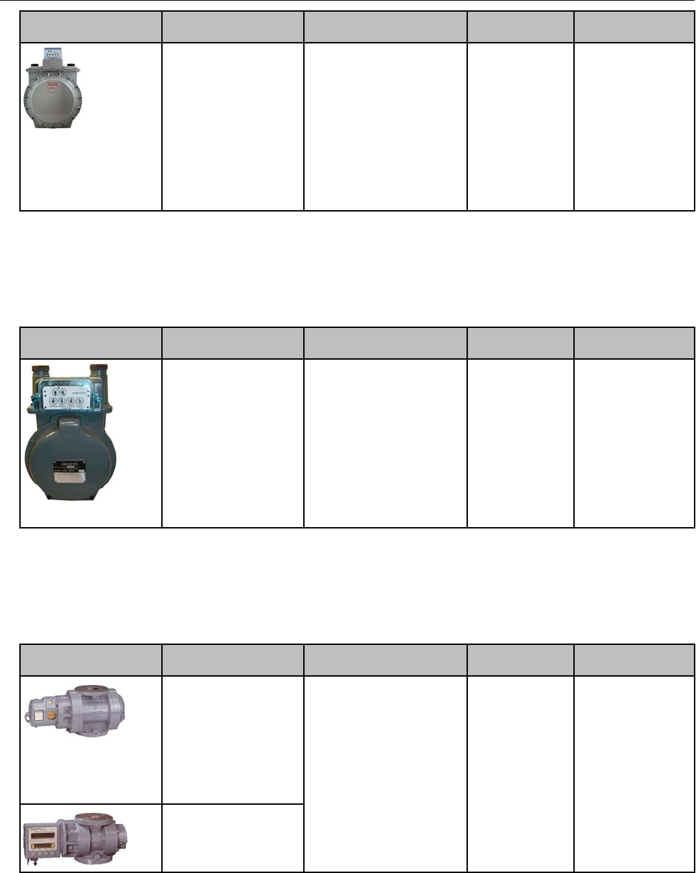
Meter model Meter notes Module type Itron part
number
ERT module notes
675, 1000
Front-mount index 500G remote ERG-7000-501 Requires a thicker
gasket for magnet
hub to clear index
box.
1-hole gasket:
FAB-0014-001
2-hole gasket:
FAB-0014-002
4-hole gasket:
FAB-0014-003
National meter installation
National/Lancaster meters are compatible with 500G remote modules with an encoder
cable. For installation instructions, see Diaphragm Meter Installation on page 63.
Meter model Meter notes Module type Itron part
number
ERT module notes
All meters
Where direct mount
solution is not
compatible
500G ERG-7000-501
Romet meter installation
This section describes installation for Romet meters and correctors compatible with Itron
500G remote ERT modules.
Meter model Meter notes Module type Itron part
number
ERT module notes
RM Series STD CTR
600-5600
TC 2000-23000
Meter must have
factory-installed pulser
with connector output.
Purchase cable
interface from
manufacturer.
500G remote ERG-7000-503
Meter must have
connector pin with
factory-installed pulse
output. Purchase correct
Specific Meter Manufacturer Installation
OpenWay Riva 500G Gas ERT Module Installation Guide, Remote Mount TDC-1678-000 52
Proprietary and Confidential
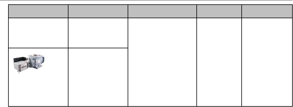
Meter model Meter notes Module type Itron part
number
ERT module notes
RM Series
Electronically
compensated meter
ECM2 600-56000
cable interface from
Romet.
AdEM® Series
Correctors including
AdEM-S®, AdEM-T®,
and AdEM®-PTZ
Must be configured to
350mS of output pulse
spacing and 30mS of
output pulse width.
Romet installation overview
500G ERT module installation with the Romet series correctors involves the following tasks.
1. Programming or verifying the that corrector is set up to work with the 500G remote ERT
module.
Programming requires a computer loaded with the RometLink software and a Romet
computer-to-corrector communication cable.
2. Connecting the ERT module to the corrector. Installation requires the following materials.
• Connection options, Cannon cable (part number: 43-035-40*) pigtail option
• Romet AdEM communication cable, available from Romet
• RometLink communication software, available from Romet
• 3 gel cap connectors, Itron part number CON-0023-001
• 3M crimping tool
• Torx T-10 screwdriver
• Remote ERT module with backplate and four included Torx screws (included with
module)
3. Mounting the remote ERT module (for more information, see Mounting the Remote 500G
ERT Module on page 9. Select the mounting option appropriate for your installation.
Mounting options include:
• Wall mount on a sheet metal surface
• Pipe mount using the Itron pipe mount kit CFG-0005-003
• Custom Romet mounting (see Romet documentation for custom mounting)
4. Programming the 500G remote ERT module. For programming information, see 500G
Remote ERT Module Programming on page 14. Programming requires an Itron ERT
programming device (for example, an FC300SR).
Specific Meter Manufacturer Installation
OpenWay Riva 500G Gas ERT Module Installation Guide, Remote Mount TDC-1678-000 53
Proprietary and Confidential
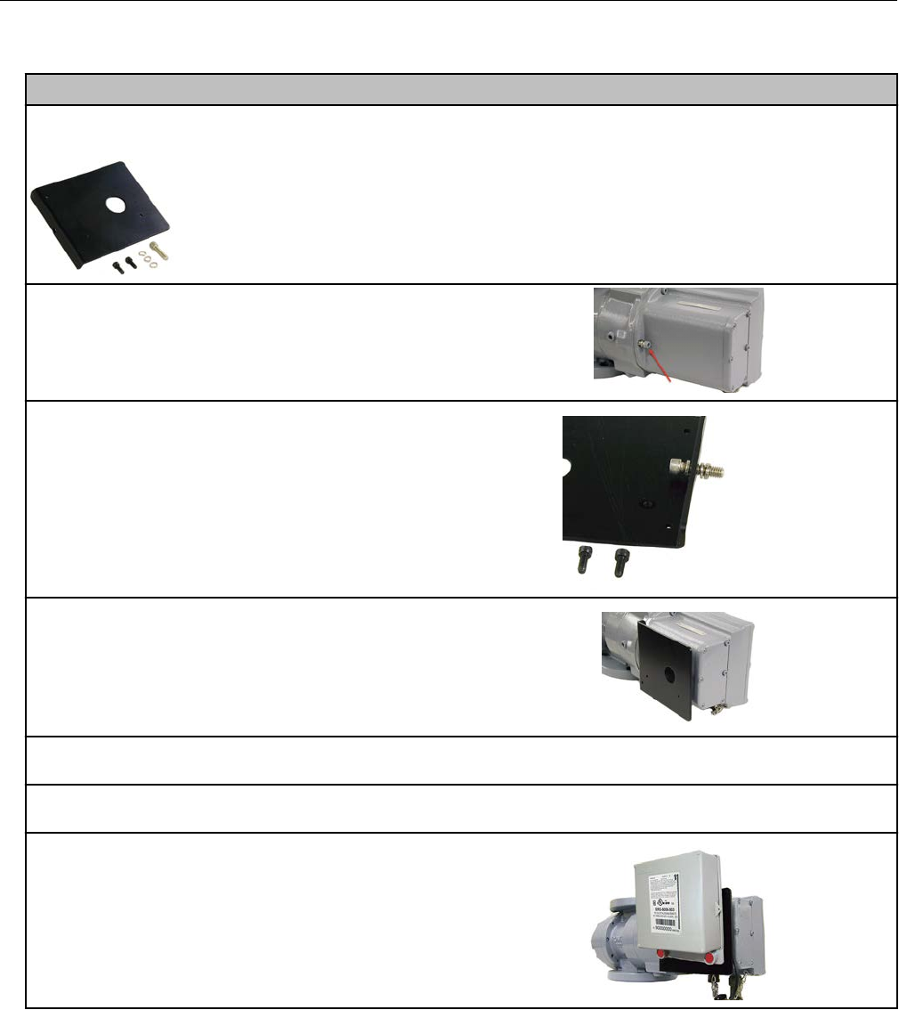
Romet product mounting instructions
Romet ECM2® to remote ERT module mounting option
Note: this mounting option requires a Romet mounting kit (Romet part number 34-444-1-KIT).
1. Remove the module screw from the back of
the ECM2 meter.
2. Insert the mounting screw fitted with the three
lock washers. Two lock washers are used as
spacers (as shown).
3. Attach the mounting plate to the meter. Insert
the mounting screw where the module screw was
removed. Torque the mounting screw to 5-7
ft.lbs. to secure the plate to the Romet meter.
4. Mount the remote module using the pre-drilled holes on the mounting plate and the module
mounting screws.
5. Place new tamper seals over the two screws. Press tamper seals into place using an 11/32-inch
nut driver or similar blunt tool.
6. Connect the module to the meter using the
previously installed cable interface.
Romet mechanical and wiring installation instructions
These instructions describe installation with Romet cables and setup options for the AdEM
corrector and ECM2® meter. These instructions include the two most common setup
configurations. For specialized setup instructions, contact Romet.
Specific Meter Manufacturer Installation
OpenWay Riva 500G Gas ERT Module Installation Guide, Remote Mount TDC-1678-000 54
Proprietary and Confidential
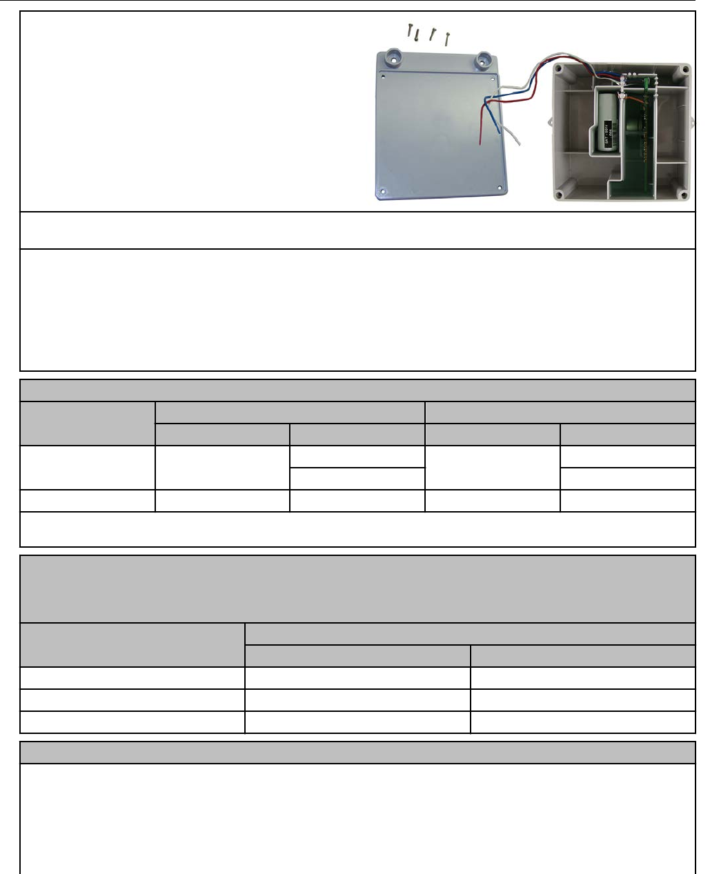
1. Remove the ERT module backplate (4 screws) to
expose the module lead wires. The backplate and
screws will be re-installed on the ERT module later
in this procedure so store them (temporarily) in a
safe, secure place.
2. Insert the lead wires from the module into new 3M gel connectors (Itron part number
CON-0023-001) together with the lead wire from the meter cable (see wiring connections).
3. Crimp the connectors using a 3M hand-held crimping tool.
Important: Use a crimping tool compatible with gel-connectors. Do not use a standard pliers for
crimping gel connectors. For more information, see Using gel-cap connectors to complete
wiring connections on page 71.
Follow the correct wiring configuration for your Romet corrector or meter from the following wiring
parameters.
Standard AdEM Romet 43-035-40 cable wiring
Connection Corrected count Uncorrected count
Romet cable ERT wire Romet cable ERT wire
Pulse Output 1+ Green White Red White
Blue Blue
Pulse Output 1- White Red Black Red
Note: This wiring configuration will not allow a cut cable tamper.
Romet PG9 pigtail cable wiring
Note: The pigtail cable is the cable extruding from the back of the AdEM corrector. You must select
the pigtail cable at the time the AdEM corrector is ordered.
Connection Corrected count
Romet cable ERT module
Pulse Output 1+ White White
Pulse Output 1- Red Red
Cut Cable Alarm Green Blue
Romet ECM2® meter wiring
The Romet ECM2® meter has three Form "A" outputs that can be configured at the factory to
provide any combination of the following three outputs:
•Uncorrected volume (UNC VOL)
• Corrected volume (COR VOL)
• Alarm
Specific Meter Manufacturer Installation
OpenWay Riva 500G Gas ERT Module Installation Guide, Remote Mount TDC-1678-000 55
Proprietary and Confidential

Romet ECM2® meter wiring
The pulse weight for the volumetric outputs is configured in SetUp Mode at Menu items > SET
UNC OUT and Menu items > SET COR OUT. Since Setup Mode is fully configurable, the ECM2®
module is universally adaptable to all Romet TC meter bodies. Reference the Romet technical
manual for specific details on the ECM2®.
Romet cable number 34-125-20
Cable pin ERT module wire
Corrected Uncorrected Alarm
A White and blue
B Red Red
C White and blue
D Red
E White and blue
Romet cable number 34-125-40 or 34-125-41
Cable pin ERT module wire
Corrected Uncorrected Alarm
A White and blue
B Red
C White and blue
D Red
E White and blue
F Red
Romet cable number 34-125-42
Cable pin ERT module wire
Corrected Uncorrected Alarm
A White and blue
B Red
C White and blue
D Red
E White and blue
F Red
Romet cable number 34-125-43
Cable pin ERT module wire
Corrected Aux CC Alarm
A White and blue
B Red
C White and blue
D Red
E White and blue
Specific Meter Manufacturer Installation
OpenWay Riva 500G Gas ERT Module Installation Guide, Remote Mount TDC-1678-000 56
Proprietary and Confidential

Romet cable number 34-125-43
Cable pin ERT module wire
Corrected Aux CC Alarm
F Red
Romet cable number 34-125-44
Cable pin ERT module wire
Aux CC
A
B
C White and blue
D Red
E
F
Romet cable number 34-125-45
Cable pin ERT module wire
Corrected Uncorrected Alarm
A White and blue
B Red
C White and blue
D Red
E White and blue
F Red
Romet cable number 34-125-50
Cable pin ERT module wire
Corrected Uncorrected Alarm
1 Red
2 White and blue
3 White and blue
4 Red
5 Red
6 White and blue
Romet cable number 34-125-51
Cable pin ERT module wire
Correct Uncorrected Aux CC
1 Red
2 White and blue
3 White and blue
4 Red
5 Red
Specific Meter Manufacturer Installation
OpenWay Riva 500G Gas ERT Module Installation Guide, Remote Mount TDC-1678-000 57
Proprietary and Confidential
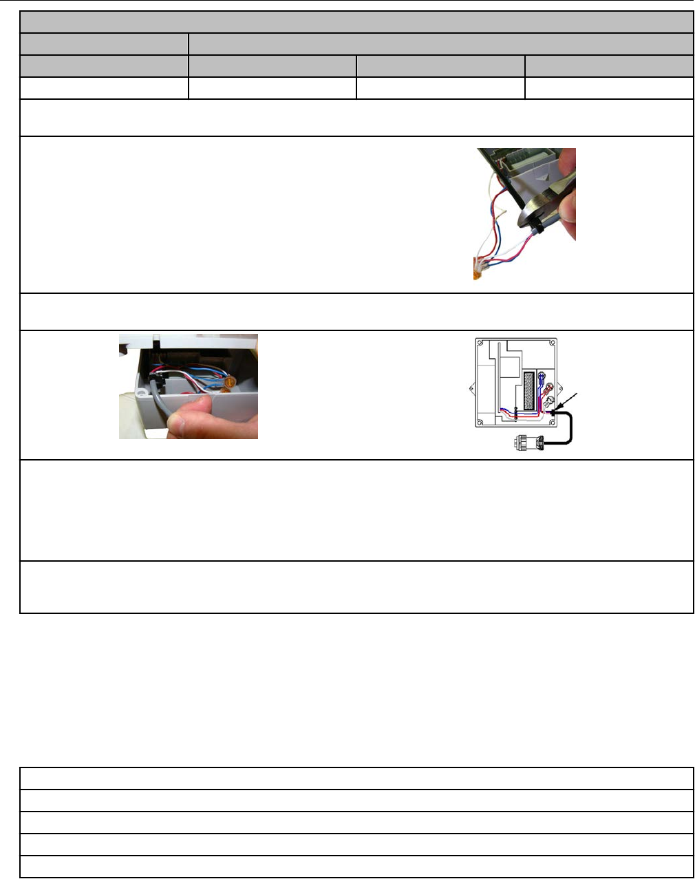
Romet cable number 34-125-51
Cable pin ERT module wire
Correct Uncorrected Aux CC
6 White and blue
4. After the wire connections are completed, install a cable tie to the meter cable just below the
exposed colored lead wires on the cable insulation.
5. Remove the excess cable tie using a hand-
held side-cutter pliers. The cable tie performs as
a cable strain relief to mitigate the risk of
destructive tension on the lead wires.
6. Tuck the three gel connectors and cable tie inside the module housing, as shown in the following
placement illustration and schematic.
7. Install the remote ERT module backplate using the four screws previously removed from the
module and a Torx T-10 screwdriver.
Important: Verify that the cable tie and gel connectors are inside the module housing and the cable
extends out of the slot in the backplate. Torque the backplate mounting screws to 9 to 12 inch-
pounds.
8. Install the module on the wall or a pipe using the pipe installation kit (Itron part number
CFG-0005-003) or install the module on the Romet AdEM meter using the Romet ERT mounting
bracket (Romet part number 46-444-2).
Romet corrector programming and requirements notes
AdEM programming
Note: Meter setup requires confirmation of communication settings with the AdEM corrector.
Communication confirmation requires the RometLink software and the Romet
communication cable.
1. Install the RometLink software on your PC.
2. Connect the AdEM corrector communication cable to your computer and the AdEM corrector.
3. Add the AdEM meter to your Phone Book.
3.a Open the RometLink software and log on.
3. b From the Talk to Unit tab, select Check > All. Click Yes.
Specific Meter Manufacturer Installation
OpenWay Riva 500G Gas ERT Module Installation Guide, Remote Mount TDC-1678-000 58
Proprietary and Confidential
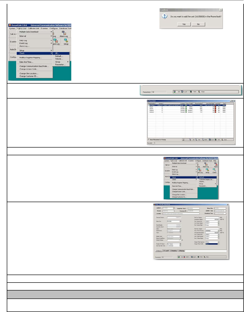
A dialog box opens asking if you want to add the unit in
the Phone Book.
3.c Click Close at the bottom of the window.
3.d Confirm the Meter was added to the Phone Book.
3.e Set up the corrected or uncorrected parameters.
3.f.1 From the Talk to Unit tab, select Setup > Default.
3.f.2 Set the following Default Setup Group
parameters:
•Enter the desired Cor. Volume Unit parameter. Set
Cor. Pulse Volume to the same number of units.
• For Output Pulse Spacing, enter the largest
number over 285mS that works for your application.
(Itron recommends a setting of 350mS.)
• For Output Pulse Width, enter the largest number
over 28mS that works for your application. (Itron
recommends a setting of 40mS.)
3.f.3 Click Send at the bottom of the page.
3.f.4 Select Current Page.
ECM2® programming
4. Set the ECM2 output pulse spacing to 750ms for operation with the 500G remote ERT module.
Output spacing represents an off-time between pulses.
Specific Meter Manufacturer Installation
OpenWay Riva 500G Gas ERT Module Installation Guide, Remote Mount TDC-1678-000 59
Proprietary and Confidential
Sensus meter installation
This section describes 500G remote ERT module on compatible Sensus meters.
Meter model Meter notes Module type Itron part
number
ERT module notes
Sonix pulse output 12,
16, 25, 57 (Metric)
600, 880, 2000 (cubic
foot)
Sonix meters are pulse
output registers which
are programmed by
Sensus software.
Proper pulse output
options and display
options must be
selected.
500G remote ERG-7000-503
Sensus meter installation overview
Installing the remote module to a Sensus meter involves tasks:
1. Programming the meter.
2. Mounting the 500G remote ERT module. The module may be mounted on a pipe or flat
surface (see Mounting the Remote 500G ERT Module on page 9). Select the mounting
option appropriate for your installation. Mounting options include:
• Wall mount on a sheet metal surface
• Pipe mount using the Itron pipe mount kit CFG-0005-003
3. Connecting the remote module to the meter.
4. Programming the remote module. For programming information, see 500G Remote ERT
Module Programming on page 14.
Sensus product mounting instructions
The Sensus factory can direct mount the 500G remote ERT module to Sensus Sonix Meters
(contact Sensus North American Gas Customer Service for mounting specifications and
ordering information). This section includes the instructions for customers to mount the
module on the Sonix meter using the mounting materials available from Sensus Metering
Systems.
Specific Meter Manufacturer Installation
OpenWay Riva 500G Gas ERT Module Installation Guide, Remote Mount TDC-1678-000 60
Proprietary and Confidential
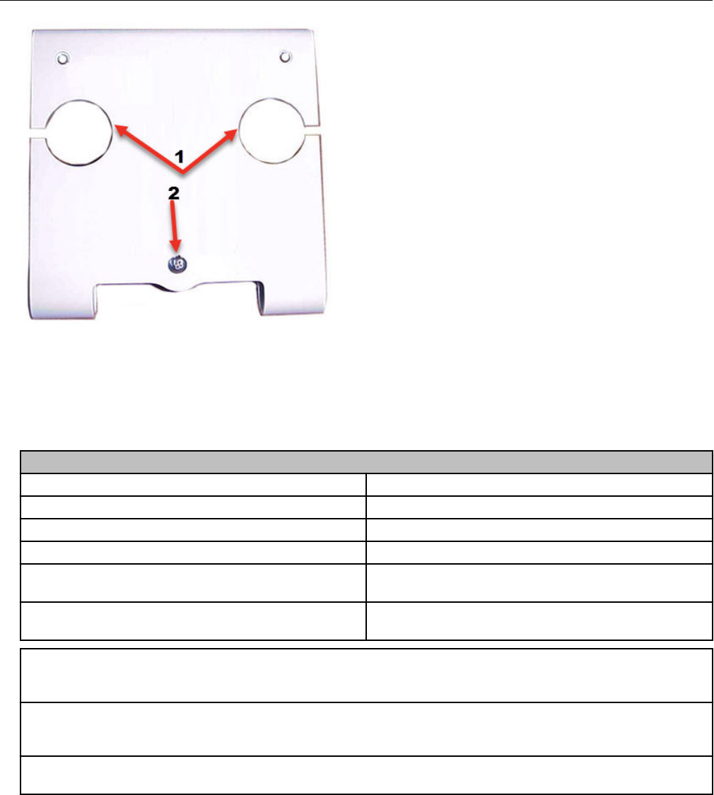
ATop anchor screw positions
BBottom anchor position for the module U-shaped mount
Sensus Sonix direct mount brackets and mounting hardware (order the correct bracket for
your installation requirements from Sensus North American Gas Customer Service.
Brackets and mounting hardware are ordered separately).
Sensus Sonix direct mount brackets* and mounting hardware
Sensus part number Description
60025-063-00000 1 1/2" FTP, 45Lt, #3 Spg, 60Lt, #4 Spg
60025-063-01000 2" - 11BS, 2" FTP
60025-063-02000 30Lt, #1A Spg, 1 1/4" NPT, #2 Spg, 20Lt
903376 #8-32 x 3/4" SS Fillister-head screws (2
required)
011-14-286-00 Rubber mounting washer (stabilizes bracket and
remote module assembly)
1. Place the ERT mounting bracket over the inlet or outlet pipe fitting on the Sonix meter. (The
default position is over the inlet connection. The inlet connection is the left side connection looking
at the front of the meter.)
2. Remove the four ERT backplate screws and turn the backplate so the ERT mounting screw
holes are to the top of the ERT module (the arrow on the ERT module label must point up). Secure
the module with the four ERT backplate screws that were previously removed.
3. Slide the mounting lug (now on the bottom of the ERT module) over the bottom anchor. Insert the
two top ERT mounting screws and tighten in an alternating pattern.
Specific Meter Manufacturer Installation
OpenWay Riva 500G Gas ERT Module Installation Guide, Remote Mount TDC-1678-000 61
Proprietary and Confidential
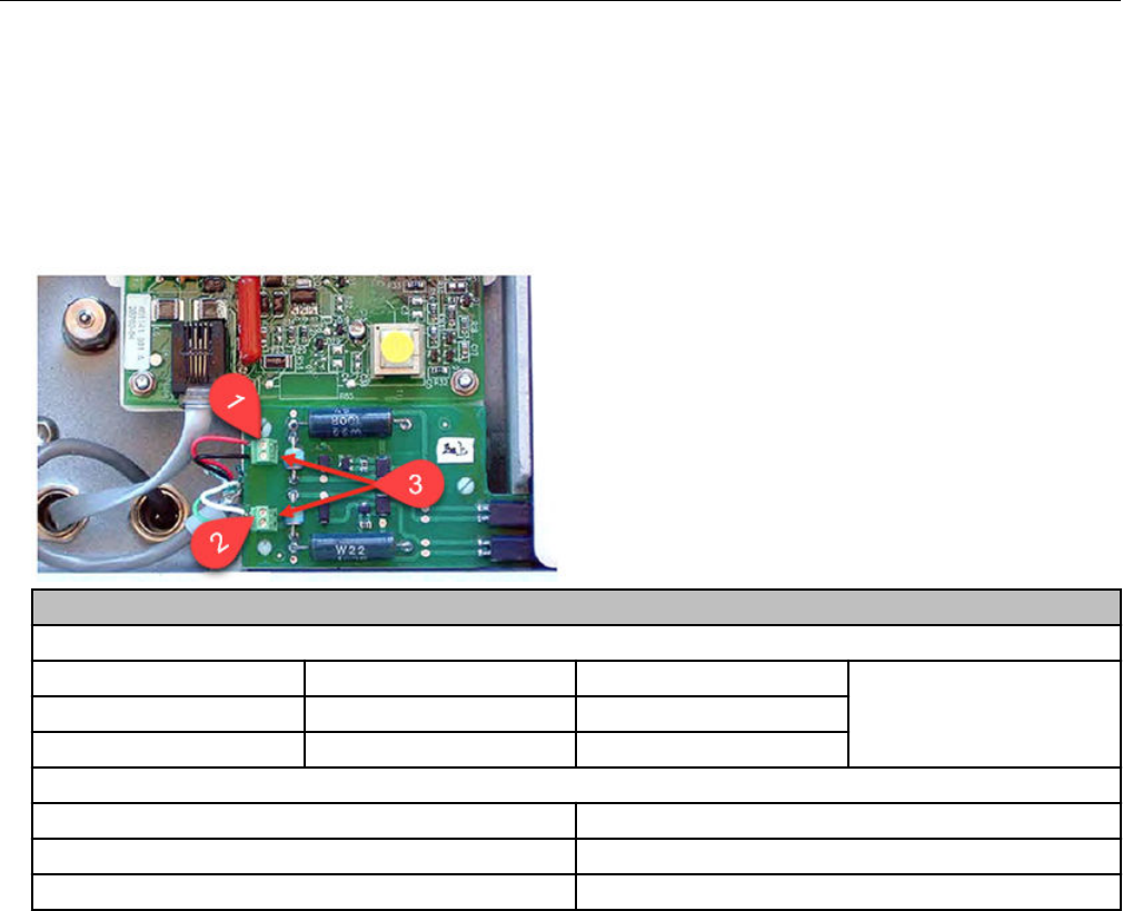
Sensus meter mechanical and wiring installation
instructions
Sensus Sonix meters provide a standard Form A electronic pulse output compatible with the
remote module. You may connect the Sensus Sonix meter to the remote module using the
pulse output cable or you can directly mount the remote ERT module to the meter.
Sensus meter wiring
Sensus Sonix 2000 meter pulse output options
Option (1) Pulse 1 (+) (2) Pulse 2 (+)
(3) Ground (-)
1 Uncorrected Corrected
2 LCD index volume Alarm
Sensus Sonix 600 or 880 meter wiring
Meter wire ERT module wire
Red White and blue
Black Red
For more information about programming wiring parameters, contact Sensus North
American Gas Customer Service.
Sensus meter programming and requirements notes
Using the SonixCom software, configure the Sensus Sonix meter parameters with the
following the Sensus pulse output settings.
• 1 pulse per 10 cf
• 1 pulse per 100 cf
• 1 pulse per 1000 cf
Specific Meter Manufacturer Installation
OpenWay Riva 500G Gas ERT Module Installation Guide, Remote Mount TDC-1678-000 62
Proprietary and Confidential

Chapter 6 Diaphragm Meter Installation
This chapter provides the instructions to install remote modules (Itron part number
ERG-500X-501 with 2.5-foot cable and encoder) on diaphragm gas meters where a direct
mount ERT module is not possible.
Meter model Meter notes Module type Itron part
number
ERT module notes
Elster American 10
Metric (10B)
Originally manufactured
by Metric Metal Works
500G remote ERG-7000-501
Itron 1A Flat-face meter where
meter body and 1A
adapter plate have
interference fit issue
causing direct mount
solution to be non-
compatible
Itron 305 #2 flat-face meter
Itron 400 #3 flat-face meter
Itron 675, 1000 Front-mount index 500G remote ERG-7000-501 Requires a thicker
gasket for magnet
hub to clear index
box.
1-hole gasket:
FAB-0014-001
2-hole gasket:
FAB-0014-002
3-hole gasket:
FAB-0014-003
National meters All meters where a
direct mount solution is
not compatible
500G remote ERG-7000-501
Diaphragm meter installation overview
Diaphragm meter installation involves the following tasks:
1. Programming the module. For programming information, see 500G Remote ERT Module
Programming on page 14.
2. Mounting the 500G remote ERT module. For mounting information, see 500G Remote
ERT Module Programming on page 14. Mounting options include:
• Wall mount on a sheet metal surface
• Pipe mount using the Itron pipe mount kit CFG-0005-003
3. Connecting the remote module to the diaphragm meter.
The following materials are required for each remote module installation to a diaphragm gas
meter. Purchase these items from Itron.
OpenWay Riva 500G Gas ERT Module Installation Guide, Remote Mount TDC-1678-000 63
Proprietary and Confidential
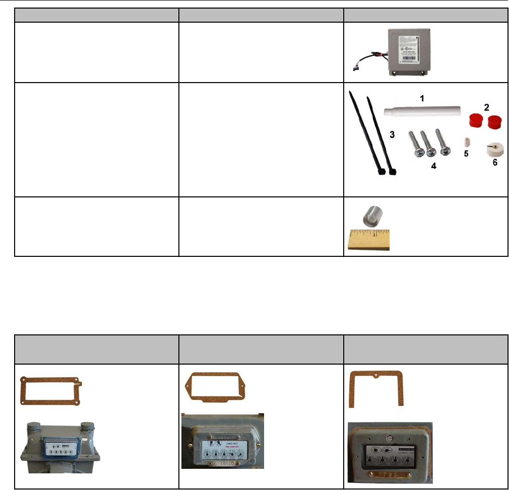
Itron part number Description
ERG-7000-501 500G remote ERT module with 2.5'
encoder cable
CFG-0081-001 Remote mount encoder kit
1. acetone applicator stick
2. tamper seals
3. cable ties
4. mounting screws
5. magnet hub spacer
6. magnet hub
013-1723-112 Encoder spacing tool. Use the Encoder
Spacing Tool to ensure that the
encoder mounts the correct distance
from the magnet hub on the meter
index.
The Itron replacement index cover gaskets shown below are thicker than standard gaskets
and have a special slot to accommodate the encoder cable. Gaskets are designed for
Schlumberger/Sprague model 675 and 1000 commercial diaphragm meters. These gaskets
may be incompatible on meters from other manufacturers; alternate cable relief procedures
may be necessary.
4-hole front cover gasket:
Itron part number FAB-0014-003
2-hole front cover gasket:
Itron part number FAB-0014-002
1-hole front cover gasket:
Itron part number FAB-0014-001
Product mounting installation instructions
For remote ERT module mounting with the diaphragm meter, see Mounting the Remote
500G ERT Module on page 9.
Diaphragm Meter Installation
OpenWay Riva 500G Gas ERT Module Installation Guide, Remote Mount TDC-1678-000 64
Proprietary and Confidential
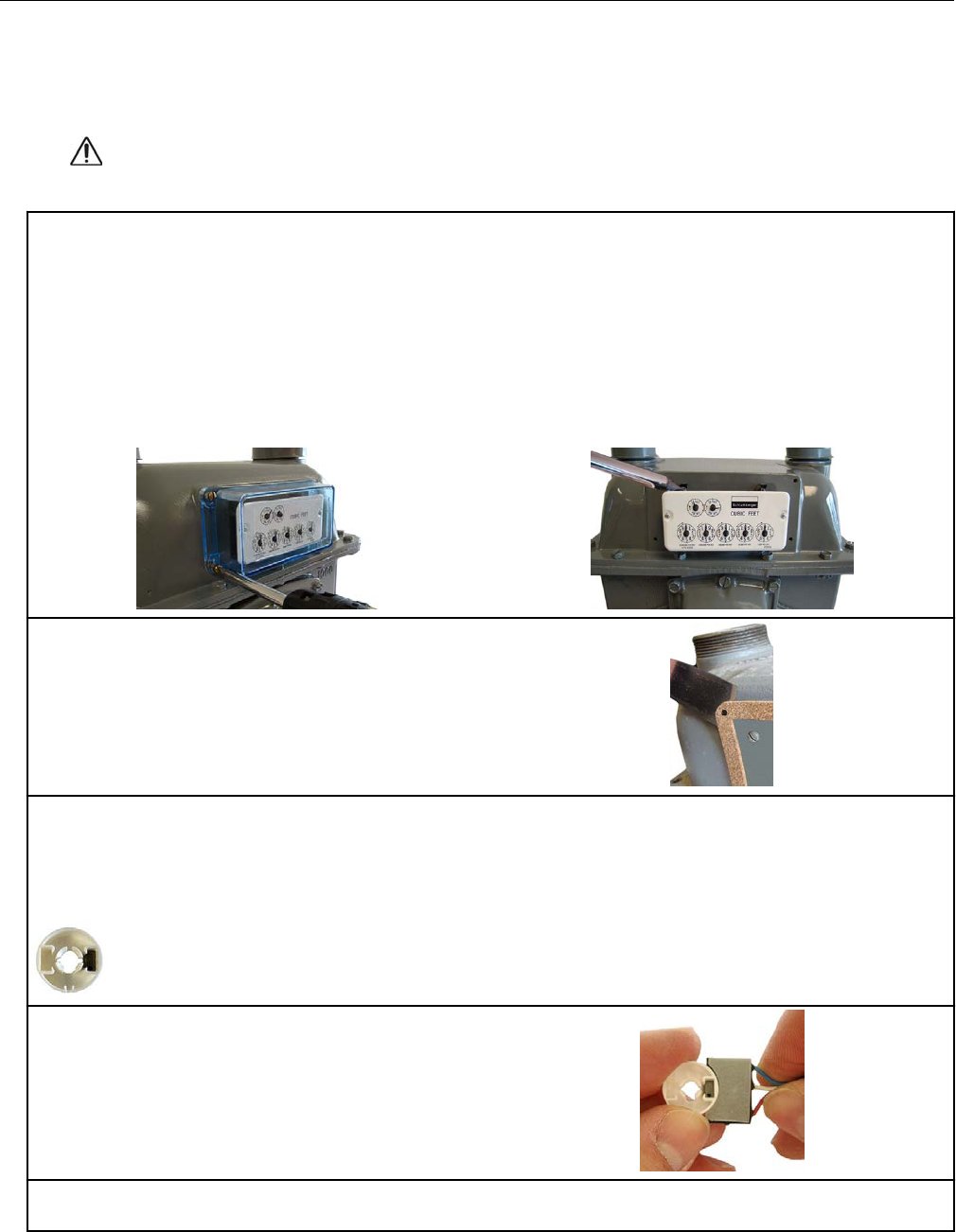
Diaphragm meter mechanical and wiring installation
instructions
Caution: The 500G remote ERT module encoder must be installed at
temperatures between 40° and 95° F to ensure proper adhesion.
1. Remove the diaphragm meter index cover and index. Use care to hold the index cover and index
while loosening the screws to protect them from damage if they are dropped.
1. Remove the index cover screws in an alternating pattern. Hold the index cover while the screws
are removed to protect it from damage due to being dropped.
2. Remove the index cover and set aside.
3. Remove the screws holding the index to the meter. Hold the index to protect it from damage due
to being dropped.
4. Set the index aside.
2. Remove the old gasket and any gasket
residue from the meter and index cover.
3. Remove the magnet hub from the encoder installation kit (Itron part number CFG-0081-001).
Verify there is only one magnet in the hub.
Note: If there is no magnet or if there are two magnets in the magnet hub, discard the hub. Encoder
installation requires a magnet hub with one magnet.
4. Briefly place the magnet side of the magnet
hub into the curved indentation in the encoder as
shown in the illustration.
Remove the magnet hub from the encoder and
set it at least one inch away from the encoder.
5. Use an ERT module programming device to read the remote module. If this reading is higher
than the reading taken after the index was removed, the remote is counting and working properly.
Diaphragm Meter Installation
OpenWay Riva 500G Gas ERT Module Installation Guide, Remote Mount TDC-1678-000 65
Proprietary and Confidential

Note: It the reading is not higher than the previous reading, the remote module is not working
properly. Repeat steps 4 and 5. If the module count is not incrementing, replace the 500G remote
ERT module and perform steps 4 and 5.
6. Align the large notch in the magnet hub spacer with the needle of the index meter drive rate dial
(1- or 2-foot for residential diaphragm meters; 5-, 10-, or 100-foot for commercial diaphragm
meters). Press the magnet hub spacer down over the dial needle as far as possible. The tip on the
bottom of the spacer may touch the index face. Turn the dial in the direction noted on the index
after the hub is in place to verify the index dial functions with a smooth, easy rotation.
7. Align the pointer (1) on the top of the magnet
hub and the notch (2) in the side of the magnet
hub with the needle (3) of the meter drive rate
dial.
8. Press the magnet hub down over the hub
spacer as far as possible. The bottom of the hub
spacer may touch the index face. Turn the dial
after magnet hub installation to verify that the
index dial functions with a smooth, easy rotation.
9. If the dial needle tip sticks out past the edge of
the magnet hub, cut off the end of the dial needle
as close as possible to the magnet hub with
sharp, side-cutting pliers.
10. Remove the acetone stick applicator from the remote encoder installation kit (Itron part number
CFG-0081-001). Select a location on the index face next to the magnet hub for the encoder
installation. After installation, the encoder cable must not interfere with the index dials.
Note: If a TEMP COMP sticker is attached to the index where the encoder cable will mount,
remove it before cleaning with the acetone stick. If the sticker (or replacement sticker) must be put
back on the register face, place it in a new location on the index face after the encoder is attached.
Diaphragm Meter Installation
OpenWay Riva 500G Gas ERT Module Installation Guide, Remote Mount TDC-1678-000 66
Proprietary and Confidential
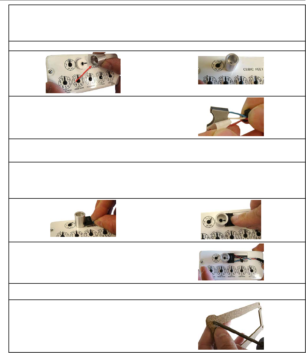
11. Tilt the acetone stick vertically with the applicator foam end down. Squeeze the acetone stick on
the black dot until the packet inside the pen breaks. Continue to hold the pen in a vertical position
until the acetone wicks into the foam applicator end. Apply a thorough coat of acetone to the index
where the encoder will be installed. Do not touch the area where the acetone was applied before
the encoder is installed.
12. Slide the thin end of the encoder spacing tool down over the magnet hub.
13. Peel the protective plastic away from the
adhesive side of the encoder.
Important: You must do the next two steps exactly as described or the 100G series remote gas
module will not work properly.
14. Press the curved side of the encoder firmly against the side of the encoder spacing tool as
shown below, with the adhesive side down. Slide the encoder down along the side of the encoder
spacing tool until it touches the surface of the index (as shown below). Using moderate pressure,
hold the encoder firmly against the index, without moving, for 15 seconds to permanently apply the
encoder.
15. Remove the encoder spacing tool and lay the
index on a flat, horizontal surface to reduce strain
on the encoder cable.
16. Program the index reading (with the encoder mounted) into the 500G remote module. Read the
remote module and verify that the reading matches the read programmed into the remote module.
17. Use the correct replacement gasket for your
meter's index. Remove the gasket center and
index cover-hole plugs from the new gasket.
Insert the index and encoder assembly through
the gasket center with the gasket's adhesive-
backed side facing the meter.
Diaphragm Meter Installation
OpenWay Riva 500G Gas ERT Module Installation Guide, Remote Mount TDC-1678-000 67
Proprietary and Confidential
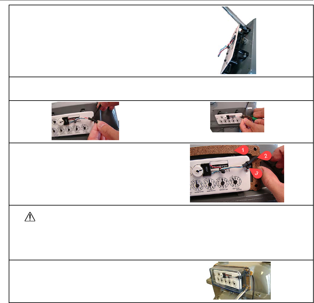
18. Align the index wriggler with the meter's drive
dog. Install the index on the meter using the
index mounting screws. Tighten one index screw
two turns. Install and tighten the remaining index
screw. Tighten the first index mounting screw
completely (alternating fashion).
19. Install a strain-relief cable tie about 1-1/4-inch from the encoder cable's stripped end. The cable
tie must be inside the index cover after the cover is installed on the meter. Remove any excess
cable tie with a side-cutting pliers and dispose the excess cable tie.
20. Remove the protective backing on the
replacement gasket to expose the adhesive side
of the gasket. Align the gasket (1), encoder cable
(2), and cable tie (for strain-relief) (3) on the
meter as shown.
Caution: Route the encoder cable inside the index cover to provide strain relief
(minimize pulling or twisting on the encoder). Verify that the strain-relief cable tie on the
encoder cable is inside the index cover when the cover is installed on the meter. The
gasket must align with the index cover screw holes and adhere to the meter face to
insure a proper seal after the index cover is installed.
21. Install the four index cover screws and
tighten just enough to hold the screws in place.
Diaphragm Meter Installation
OpenWay Riva 500G Gas ERT Module Installation Guide, Remote Mount TDC-1678-000 68
Proprietary and Confidential
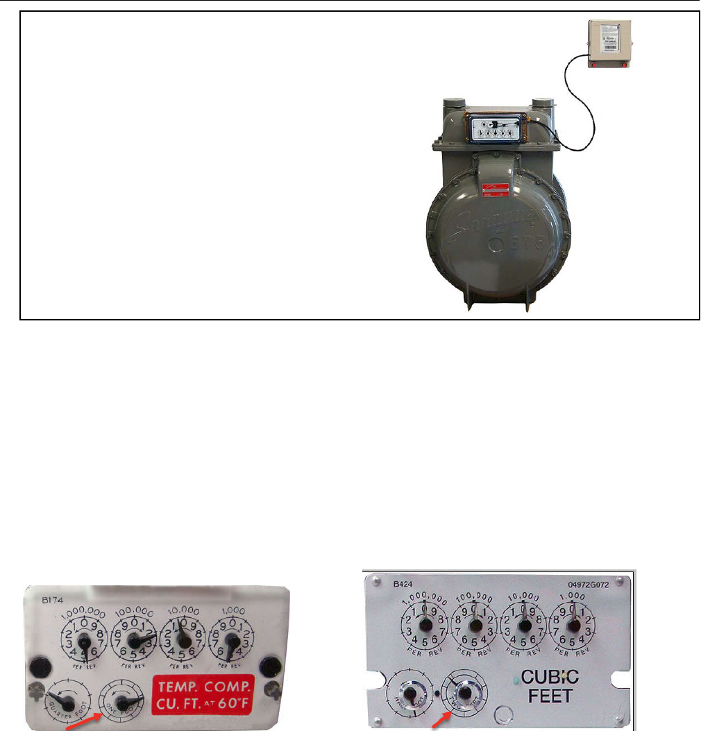
22. Verify that the encoder cable is in the correct
position in the cable slot of the gasket. Fully
tighten the screws in an alternating pattern.
Install utility-approved security seals and wires
as required.
Remote ERT module programming and requirements
notes
For remote ERT module programming, see 500G Remote ERT Module Programming on
page 14.
Residential module programming notes:
The ERT module is programmed based on the meter's drive rate. Take note of the index
drive rate shown on a lower dial on the index. Elster American meter index drive rates are
either 1-cubic foot, 2-cubic feet or 0.05 cubic meters (not shown below).
Commercial module programming notes:
Take note of the index drive rate shown on the index. The ERT is programmed based on the
drive rate. Elster American commercial meter index drive rates may be 5-, 10- or 100 cubic
feet. The index shown has a 10-cubic foot drive rate.
Diaphragm Meter Installation
OpenWay Riva 500G Gas ERT Module Installation Guide, Remote Mount TDC-1678-000 69
Proprietary and Confidential
Diaphragm Meter Installation
OpenWay Riva 500G Gas ERT Module Installation Guide, Remote Mount TDC-1678-000 70
Proprietary and Confidential
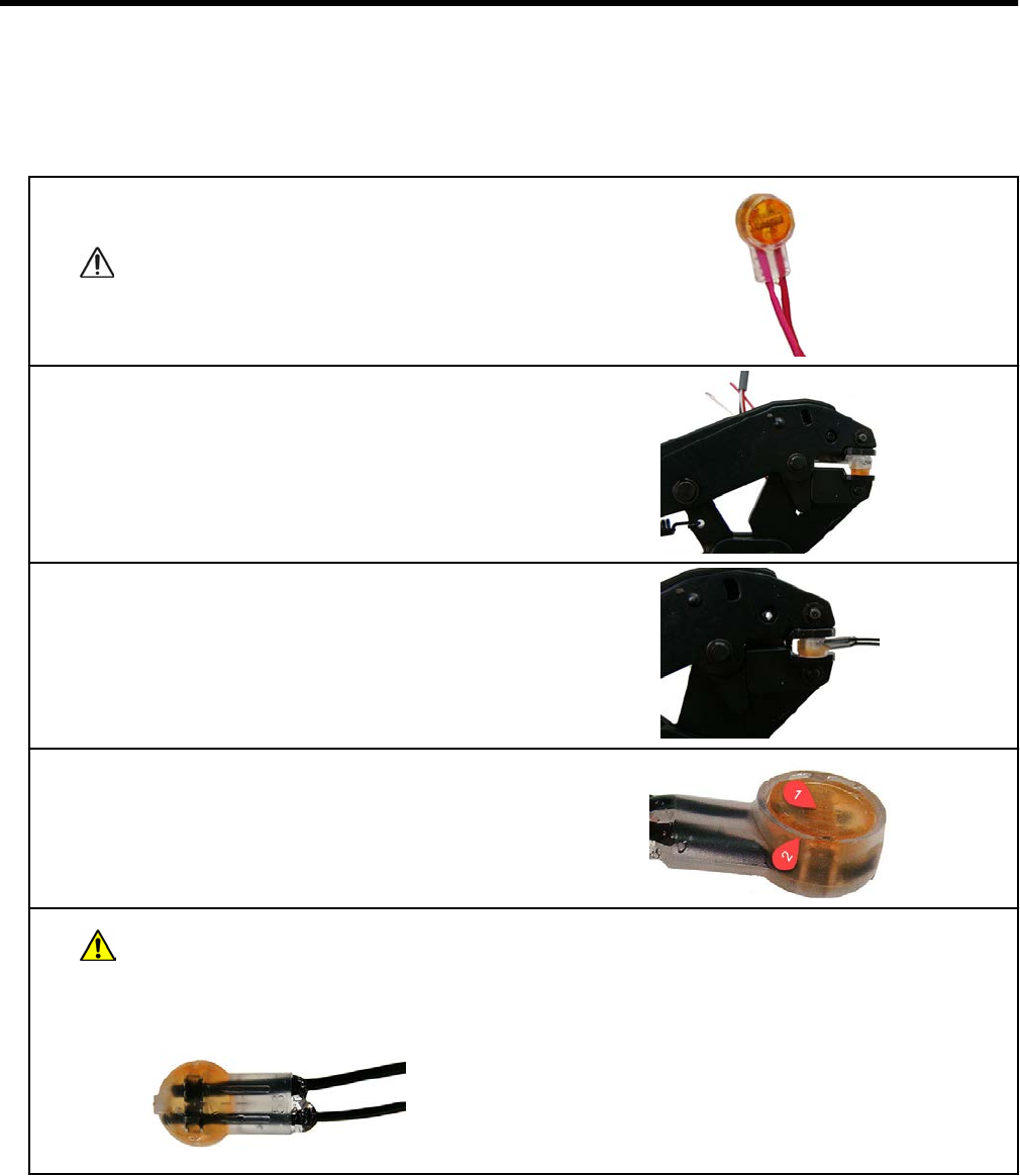
Appendix A Using gel-cap connectors to
complete wiring connections
This section provides the instructions to complete remote ERT module to meter wiring
connections. Gel-cap connections require:
• E-9R 3M® gel-cap crimping tool
• 3M gel-cap connectors (Itron part number CON-0023-001)
1. Push the two wires into the connector as far as
possible.
Caution: Do not strip insulation from
the ends of the wires before
inserting them into the connector.
2. Place the connector and connector wires into
the jaws of the crimping tool. Ensure that the
wires remain fully inserted in the connector.
3. Squeeze the handles to crimp the connector.
Apply pressure until the cap is fully seated (at
least three seconds).
4. The connector is properly crimped when the
top of the moveable yellow center (1) is flush with
the top of the connector body (2).
Warning: Crimping the connector forces sealant out of the connector. The sealant
protects the inside of the connector against insects, moisture, or other contaminants.
The sealant may cause minor eye and skin irritation. Avoid eye contact. For more
information or Safety Data Sheet (SDS) information, visit the manufacturer website.
OpenWay Riva 500G Gas ERT Module Installation Guide, Remote Mount TDC-1678-000 71
Proprietary and Confidential
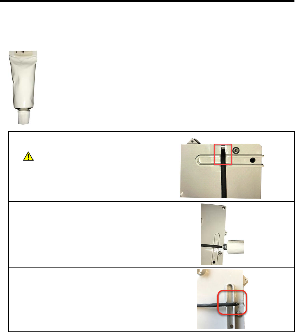
Appendix B Optional sealant application
instructions
In areas where insect intrusion is a problem, Itron recommends an optional sealant to help
keep insects out of the ERT module housing. The Itron-tested and approved sealant (Itron
part number ADH-5106-000) is used to seal gaps in remote ERT module installations that
can allow insect intrusion.
1. Prepare the module for the sealant by verifying
the application area is clean and dry.
Warning: Apply sealant in a well-
ventilated area.
2. Itron recommends sealant application after the
remote module is installed so the cable is in the
installation position. Use the sealant
(ADH-5106-000) to fill the gap.
3. Use enough sealant to fill the gap. Wipe off
any excess sealant and replace the cover on the
sealant tube.
OpenWay Riva 500G Gas ERT Module Installation Guide, Remote Mount TDC-1678-000 72
Proprietary and Confidential