Itron 925 Commercial and Industrial (C&I;) Meter without pager User Manual Operational Instruction
Silver Spring Networks Commercial and Industrial (C&I;) Meter without pager Operational Instruction
Itron >
Contents
- 1. Operational Instruction
- 2. Installation Instruction 25cmRF/DSSw-pager. (old)
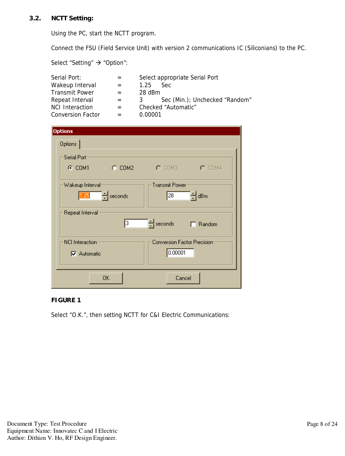
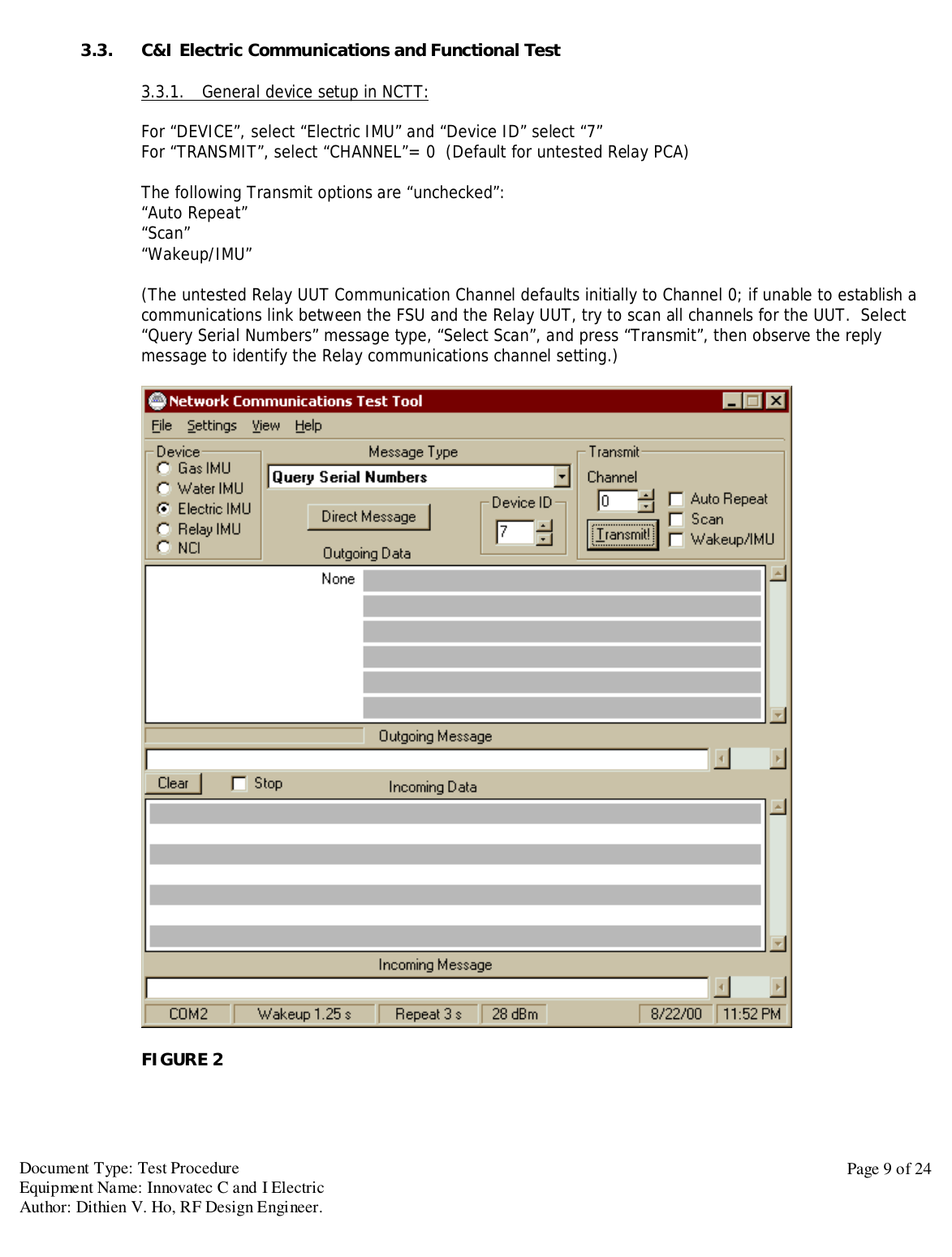
Operational Instruction
![Document Type: Test ProcedureEquipment Name: Innovatec C and I ElectricAuthor: Dithien V. Ho, RF Design Engineer.Page 10 of 243.3.1. [Query Serial Number]Select Query Serial Numbers and select “Transmit!”Observer for the “Incoming Message”, make sure the FSU (Field Service Unit) are communicating withthe UUT, and reporting the correct serial number for attached Meter (Either Landis & Gyr, Vectron orapplicable Device)FIGURE 3METER S/N REPORTED: ______________________C&I DEVICE S/N REPORTED: ______________________Pass__Fail___](https://usermanual.wiki/Itron/925.Operational-Instruction/User-Guide-124341-Page-10.png)
![Document Type: Test ProcedureEquipment Name: Innovatec C and I ElectricAuthor: Dithien V. Ho, RF Design Engineer.Page 11 of 243.3.2. [Set Serial Number]Set “Electric USN” = Type in the C&I Serial Number then press “Transmit”Make sure to obtain a “Acknowledgement Message “ reply from Incoming DataPass__Fail___FIGURE 4](https://usermanual.wiki/Itron/925.Operational-Instruction/User-Guide-124341-Page-11.png)
![Document Type: Test ProcedureEquipment Name: Innovatec C and I ElectricAuthor: Dithien V. Ho, RF Design Engineer.Page 12 of 243.3.3. [Set Communication Parameters]RF CHANNEL = INITIAL CHANNELLCD UPDATE RATE = 1BLINK RATE = 1Press “TRANMIT”Make sure to obtain a “Acknowledgement Message “ reply from Incoming DataPass__Fail___FIGURE 5](https://usermanual.wiki/Itron/925.Operational-Instruction/User-Guide-124341-Page-12.png)
![Document Type: Test ProcedureEquipment Name: Innovatec C and I ElectricAuthor: Dithien V. Ho, RF Design Engineer.Page 13 of 243.3.4. [Query Status]Select “Query Status for Message Type” then press “Transmit”Make sure to obtain a reply from Incoming DataPass__Fail___FIGURE 6](https://usermanual.wiki/Itron/925.Operational-Instruction/User-Guide-124341-Page-13.png)
![Document Type: Test ProcedureEquipment Name: Innovatec C and I ElectricAuthor: Dithien V. Ho, RF Design Engineer.Page 14 of 244. Final Assembly TestThe following test is to be performed after the PCA Assembly has been tested and install into appropriate Relayhousing unit.4.1. General TestRepeat step 3.3.2. and step 3.3.3., if necessary.4.1.1. [Set Clock]Select “Set Clock” message, enter the applicable data then press “Transmit”Observe “Acknowledged Message “ reply in Incoming Data (See Figure 7)Pass__Fail__FIGURE 7](https://usermanual.wiki/Itron/925.Operational-Instruction/User-Guide-124341-Page-14.png)
![Document Type: Test ProcedureEquipment Name: Innovatec C and I ElectricAuthor: Dithien V. Ho, RF Design Engineer.Page 15 of 244.1.2. [Query Clock]Select “Query Clock” message, enter the appropriate Relay Serial Number,and press “Transmit”Observe “Acknowledged Message” reply in the Incoming Data fields (See Figure 8)Verify Calendar and Clock settings.Pass__Fail__FIGURE 8](https://usermanual.wiki/Itron/925.Operational-Instruction/User-Guide-124341-Page-15.png)
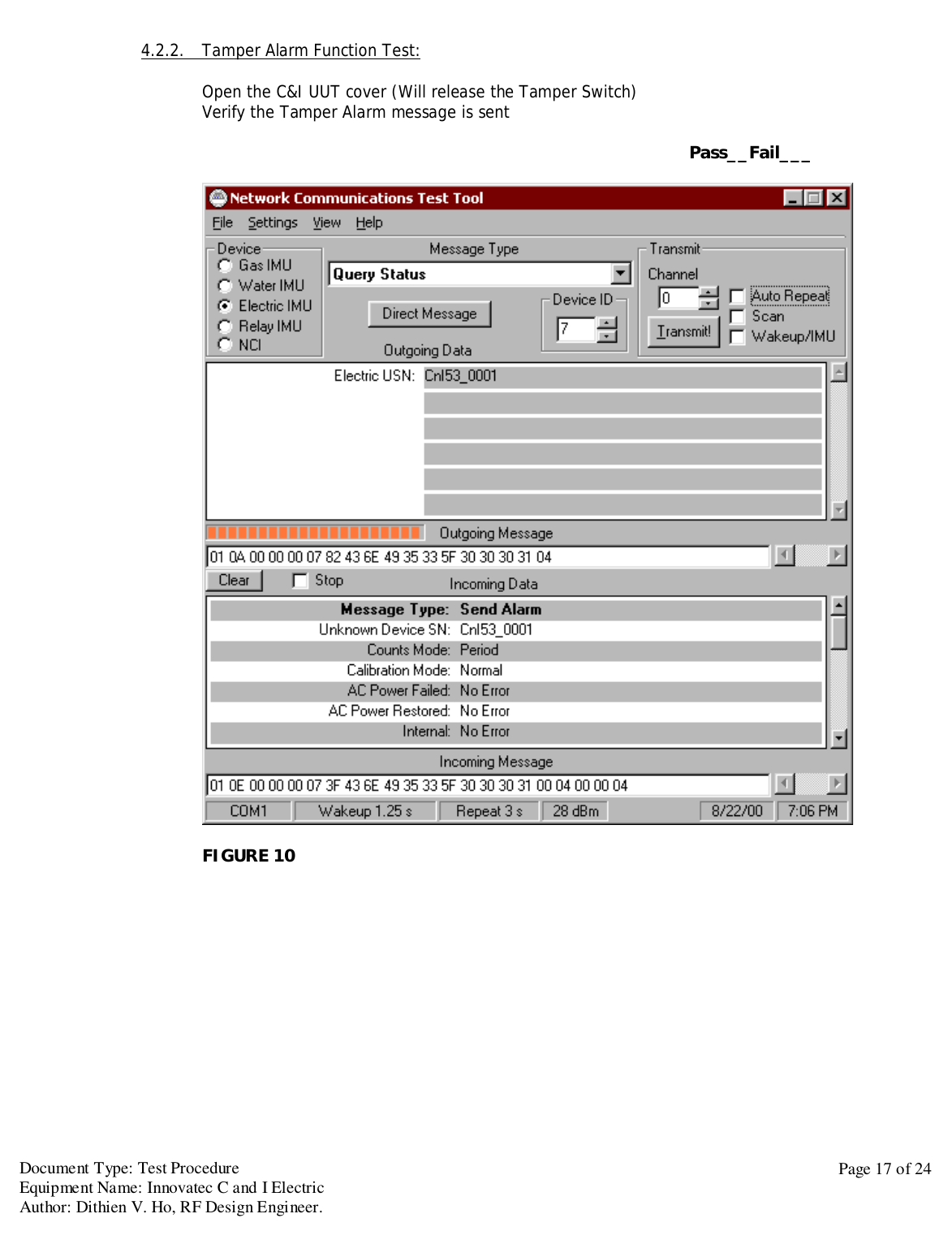
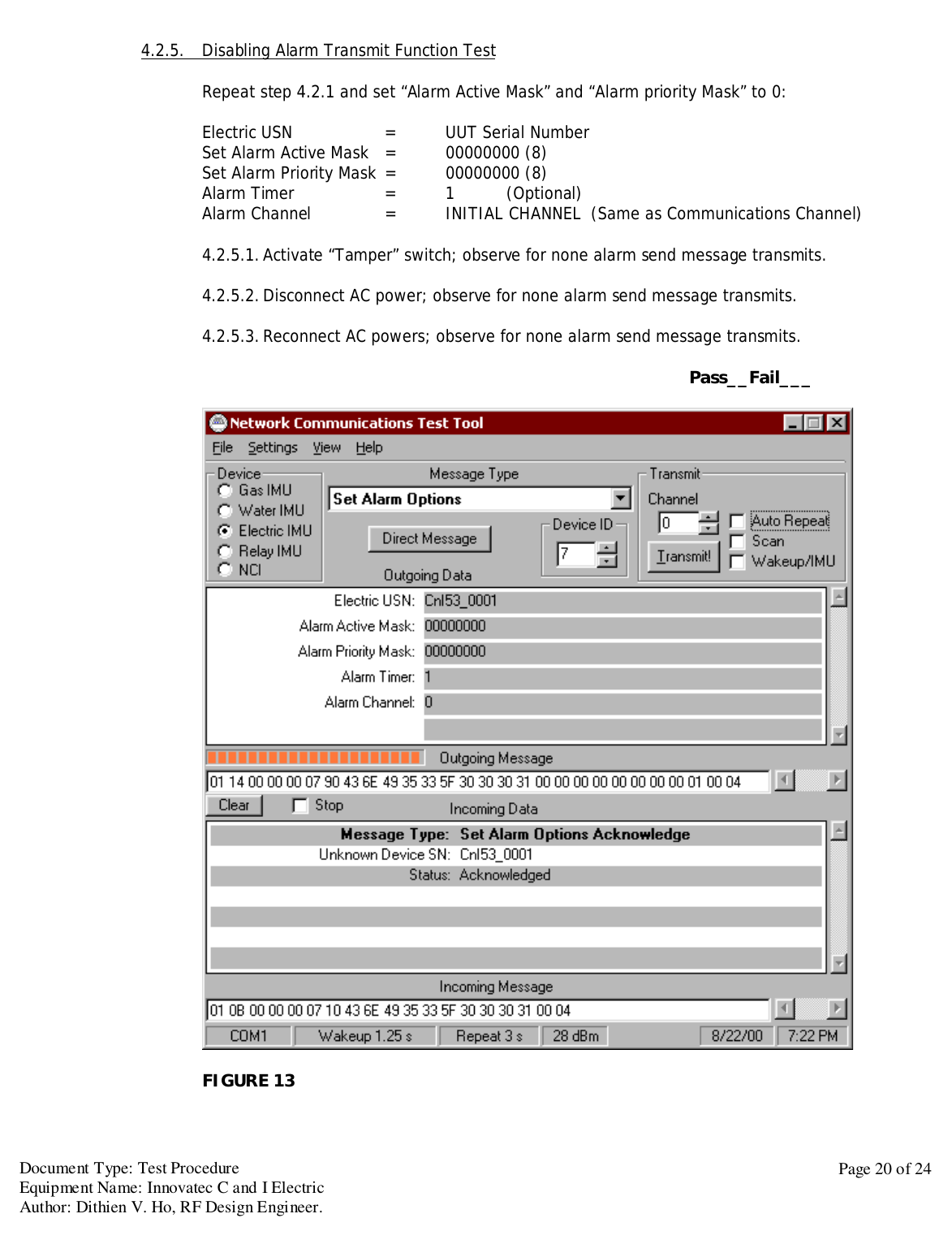
![Document Type: Test ProcedureEquipment Name: Innovatec C and I ElectricAuthor: Dithien V. Ho, RF Design Engineer.Page 16 of 244.2. Alarms Test:4.2.1. [Set Alarm Option]Electric USN = UUT Serial NumberSet Alarm Active Mask = FFFFFFFF (8)Set Alarm Priority Mask = FFFFFFFF (8)Alarm Timer = 1 (Optional)Alarm Channel = INITIAL CHANNEL (Same as Communications Channel)Pass__Fail___FIGURE 9](https://usermanual.wiki/Itron/925.Operational-Instruction/User-Guide-124341-Page-16.png)

![Document Type: Test ProcedureEquipment Name: Innovatec C and I ElectricAuthor: Dithien V. Ho, RF Design Engineer.Page 21 of 244.3. Actuators Test:4.3.5. [Set Actuator 1 Output]Type in Electric USN = C&I UUT Serial NumberSet Actuator 1 = ONSet Actuator 2 = OFFPress “Transmit”Make sure to obtain a “Acknowledgement Message “ reply from Incoming DataUse DVM to verify between Pin 1, J10 (Actuator 1 Output) and Pin 3, J10 (Actuator 1) Commonare “Closed”Use DVM to verify between Pin 2, J10 (Actuator 2 Output) and Pin 4, J10 (Actuator 2) Commonare “Open”Pass__Fail___FIGURE 13](https://usermanual.wiki/Itron/925.Operational-Instruction/User-Guide-124341-Page-21.png)
![Document Type: Test ProcedureEquipment Name: Innovatec C and I ElectricAuthor: Dithien V. Ho, RF Design Engineer.Page 22 of 244.3.6. [Set Actuator 2 Output]Type in Electric USN = C&I UUT Serial NumberSet Actuator 1 = OFFSet Actuator 2 = ONPress “Transmit”Make sure to obtain a “Acknowledgement Message “ reply from Incoming DataUse DVM to verify between Pin 1, J10 (Actuator 1 Output) and Pin 3, J10 (Actuator 1) Commonare “Open”Use DVM to verify between Pin 2, J10 (Actuator 2 Output) and Pin 4, J10 (Actuator 2) Commonare “Close”Pass__Fail___FIGURE 14](https://usermanual.wiki/Itron/925.Operational-Instruction/User-Guide-124341-Page-22.png)
![Document Type: Test ProcedureEquipment Name: Innovatec C and I ElectricAuthor: Dithien V. Ho, RF Design Engineer.Page 23 of 244.4. Battery Power Sustain Test:4.4.5. Disconnect the ac power to the C&I UUT4.4.6. [Query Serial Number]Verify to obtain the correct Serial Number report for the C&I UUT.Pass__Fail___FIGURE 15](https://usermanual.wiki/Itron/925.Operational-Instruction/User-Guide-124341-Page-23.png)