Itron 925 Commercial and Industrial (C&I;) Meter without pager User Manual Operational Instruction
Silver Spring Networks Commercial and Industrial (C&I;) Meter without pager Operational Instruction
Itron >
Contents
- 1. Operational Instruction
- 2. Installation Instruction 25cmRF/DSSw-pager. (old)
Operational Instruction

C&I Electric
Unit Test Procedure
Revision A
August 22, 2000

Document Type: Test Procedure
Equipment Name: Innovatec C and I Electric
Author: Dithien V. Ho, RF Design Engineer.
Page 2 of 24
Table of Contents
1. Equipment Requirements
2. PCA Sub-Assembly Power Supply Function Test
3. PCA Sub-Assembly RF Communications Test
4. Final Assembly Test
5. Shipping Preparation

Document Type: Test Procedure
Equipment Name: Innovatec C and I Electric
Author: Dithien V. Ho, RF Design Engineer.
Page 3 of 24
1. Equipment Requirements
DVM (Digital voltmeter) with ohm and amp functions.
(Bel MERIT, DX451)
Dual Channel Oscilloscope, 100 MHz, 1GBs
(Tektronix, TDS 220)
Variable/Isolation AC Transformer (VIT), 0-150 Vac, 4 Amp
(Global Specialties, 1504)
PC with Windows 95 Operating System
NCTT, Test software, Version 2.2.0 or later
Field Service Unit with Version 2 Communications Chip (Siliconians) NCI installed
Unit Under Test (UUT), in this case the C&I Electric Unit, Fab. Rev. 5.3 or higher, Firmware Ver. 23 or
higher (CnI_V23.HEX, CS = 1c59)
(Innovatec, Relay, Rev. 5.3 or later)
Note: The information in parentheses is a suggested test equipment Manufacturer and Model.
Equivalents may be substituted.

Document Type: Test Procedure
Equipment Name: Innovatec C and I Electric
Author: Dithien V. Ho, RF Design Engineer.
Page 4 of 24
2. PCA Sub-Assembly Power Supply and Battery Charger Function Test
The following test in this section is to be performed before the PCA is installed into the Relay Housing.
2.1. Visual Inspection
2.1.1 Verify that the following components are installed with proper orientation / polarity, per assembly
drawings: IC’s, Transistors, Diodes, Capacitors and Transformer.
2.1.2 Check for solder bridges/solder splash across traces or other conductors.
Pass____Fail___
2.2. Continuity Tests
2.2.1 Perform continuity test using DVM between metal tabs of U1, D2 and their heatsinks.
It should be open circuit or > 10 Meg Ohms for U1 and > 2 Meg Ohms for D2.
Pass____Fail___
2.2.2 Perform continuity test between input AC line connectors (J3 to J4) and line to ground (J3-H to
J1-G and J4-N to J1-G). Should be open circuit or >2 Meg Ohms.
Pass____Fail___

Document Type: Test Procedure
Equipment Name: Innovatec C and I Electric
Author: Dithien V. Ho, RF Design Engineer.
Page 5 of 24
2.3. Power Supply Test
2.3.1. Connect 220 V variac (with isolation transformer and built-in fuse) to the input connector of
power supply. Then, slowly bring up the voltage from 0 –85V while monitoring the line current.
The line current at 85V should be < 15 mA Pass____Fail___
2.3.2. Wait few seconds and then verify all LEDs are turned on. Pass____Fail___
2.3.3. Measure the DC voltage between pins 3 and 21 of NCI connector (J7).
Specification: 5.5 – 5.7V DC. Pass____Fail___
2.3.4. Measure DC voltage between pins 15 and 21 of NCI connector (J7).
Specification: 5.0 to 5.1 Vdc Pass____Fail___
2.3.5. Measure DC voltage between pins 17 and 21 of NCI connector (J7).
Specification: 3.5 to 3.7 Vdc Pass____Fail___
2.3.6. Measure DC voltage between pins 2 and 5 of Molex connector (JP2).
Specification: 12 to 14 Vdc Pass____Fail___
2.3.7. Disconnect AC Power to UUT and install NCI unit onto the main board. Then, bring the voltage
slowly up to 85 Vac and repeat the above steps 4.2- 4.6. Pass____Fail___
2.3.8. Bring up the AC line voltage slowly from 85 to 265 Vac and repeat the above steps with NCI
installed (full-load). Pass____Fail___

Document Type: Test Procedure
Equipment Name: Innovatec C and I Electric
Author: Dithien V. Ho, RF Design Engineer.
Page 6 of 24
2.4. Battery Charger Tests
2.4.1. Connect battery charger module to C&I main board connector (JP2) and verify that the voltage
across BAT + and BAT- on the charger board is set to 6.9 Vdc with 680 Ohm resistor connected
across battery leads. Otherwise, adjust R7 Pot to set battery voltage to 6.9Vdc.
Pass__Fail___
2.4.2. Connect battery leads to the battery terminals and verify that voltage across battery terminals
has reached to 6.9Vdc (fully charged). Pass__Fail___
2.4.3. Disconnect AC power to C&I main board and verify that the LEDs stays on (good indication that
UUT is powered by battery only). Pass__Fail___
2.4.4. Remove battery charger module from C&I board with battery leads disconnected from battery
terminals. Then connect a dc power supply to battery leads and slowly increase the voltage from
0-6.5 Vdc while monitoring battery status pin (JP1-4). Verify that battery status pin goes high at
5.25 Vdc Pass__Fail___
2.4.5. Then, lower the dc Power supplies voltage slowly and verify that battery status pin (JP1-4) goes
low at 5.0Vdc.
Pass__Fail___

Document Type: Test Procedure
Equipment Name: Innovatec C and I Electric
Author: Dithien V. Ho, RF Design Engineer.
Page 7 of 24
3. PCA Sub-Assembly RF Communications Test
3.1. System Hardware Set-up:
3.1.1. Firmware Installation:
Remove AC line voltage from PCA power leads.
Disconnect battery lead from Charger Assembly.
Verify installation of the EPROM with appropriate firmware reversion.
3.1.2. NCI Installation:
Install the NCI with version 2 communications IC (Siliconians) onto the PCA with appropriate
antenna, 900 MHz, and 50 Ohms impedance.
3.1.3. Electric Meter RS-232 Communication connection:
Install the Electric Meter to connector J7 as follow:
J7, Pin 12 = Transmit (Pin 2 of the DB9 Meter communications cable)
J7, Pin 11 = Receive (Pin 3 of the DB9 Meter communications cable)
J7, Pin 10 = Ground (Pin 5 of the DB9 Meter communications cable)
Power up the electric meter.
3.1.4. Power on test:
Apply 120V AC line voltage to the PCA power leads, observe for the Status Indicator LEDs, make
sure the Green and Yellow LEDs are illuminated.
Reconnect battery lead to Charger Assembly.
Pass__Fail___
Document Type: Test Procedure
Equipment Name: Innovatec C and I Electric
Author: Dithien V. Ho, RF Design Engineer.
Page 8 of 24
3.2. NCTT Setting:
Using the PC, start the NCTT program.
Connect the FSU (Field Service Unit) with version 2 communications IC (Siliconians) to the PC.
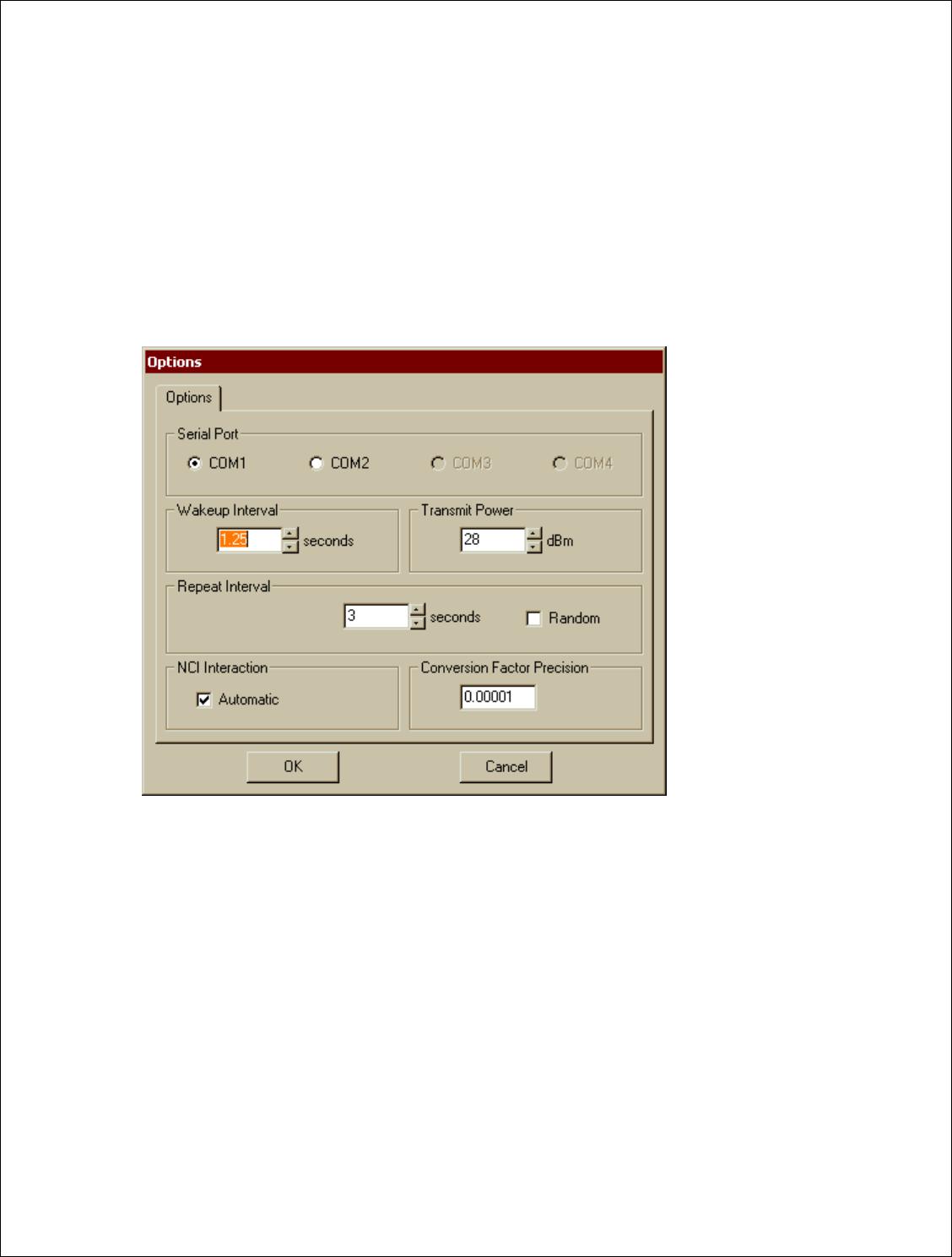
Select “Setting” ! “Option”:
Serial Port: = Select appropriate Serial Port
Wakeup Interval = 1.25 Sec
Transmit Power = 28 dBm
Repeat Interval = 3 Sec (Min.); Unchecked “Random”
NCI Interaction = Checked “Automatic”
Conversion Factor = 0.00001
FIGURE 1
Select “O.K.”, then setting NCTT for C&I Electric Communications:
Document Type: Test Procedure
Equipment Name: Innovatec C and I Electric
Author: Dithien V. Ho, RF Design Engineer.
Page 9 of 24
3.3. C&I Electric Communications and Functional Test
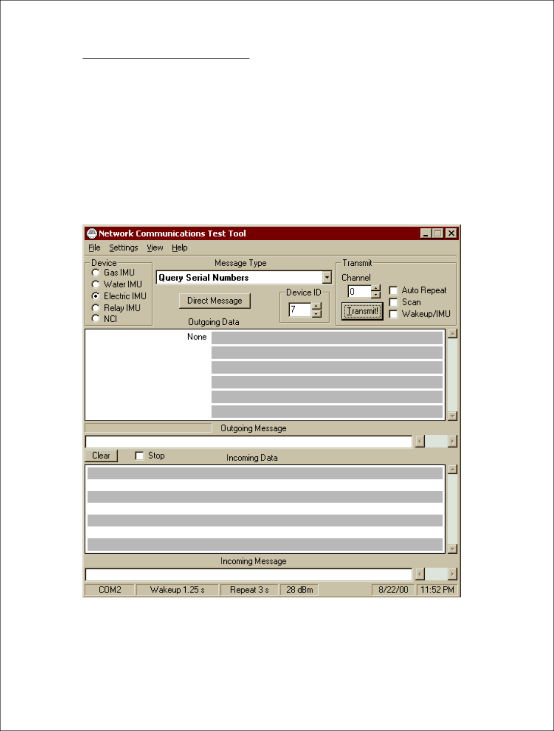
3.3.1. General device setup in NCTT:
For “DEVICE”, select “Electric IMU” and “Device ID” select “7”
For “TRANSMIT”, select “CHANNEL”= 0 (Default for untested Relay PCA)
The following Transmit options are “unchecked”:
“Auto Repeat”
“Scan”
“Wakeup/IMU”
(The untested Relay UUT Communication Channel defaults initially to Channel 0; if unable to establish a
communications link between the FSU and the Relay UUT, try to scan all channels for the UUT. Select
“Query Serial Numbers” message type, “Select Scan”, and press “Transmit”, then observe the reply
message to identify the Relay communications channel setting.)
FIGURE 2
Document Type: Test Procedure
Equipment Name: Innovatec C and I Electric
Author: Dithien V. Ho, RF Design Engineer.
Page 10 of 24
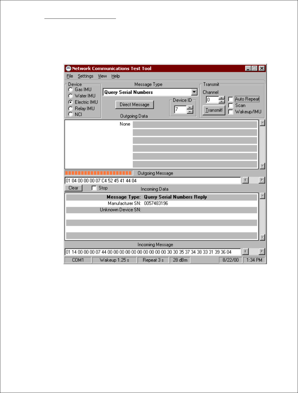
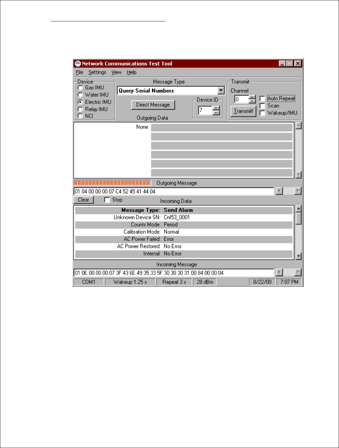
3.3.1. [Query Serial Number]
Select Query Serial Numbers and select “Transmit!”
Observer for the “Incoming Message”, make sure the FSU (Field Service Unit) are communicating with
the UUT, and reporting the correct serial number for attached Meter (Either Landis & Gyr, Vectron or
applicable Device)
FIGURE 3
METER S/N REPORTED: ______________________
C&I DEVICE S/N REPORTED: ______________________
Pass__Fail___

Document Type: Test Procedure
Equipment Name: Innovatec C and I Electric
Author: Dithien V. Ho, RF Design Engineer.
Page 11 of 24
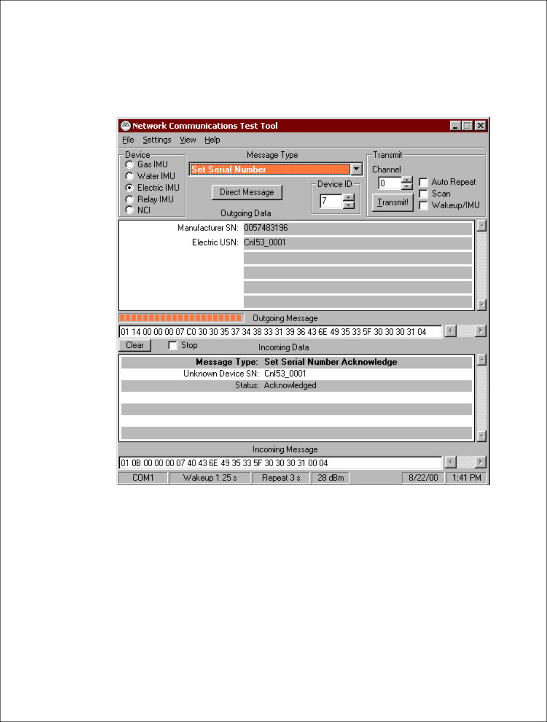
3.3.2. [Set Serial Number]
Set “Electric USN” = Type in the C&I Serial Number then press “Transmit”
Make sure to obtain a “Acknowledgement Message “ reply from Incoming Data
Pass__Fail___
FIGURE 4
Document Type: Test Procedure
Equipment Name: Innovatec C and I Electric
Author: Dithien V. Ho, RF Design Engineer.
Page 12 of 24
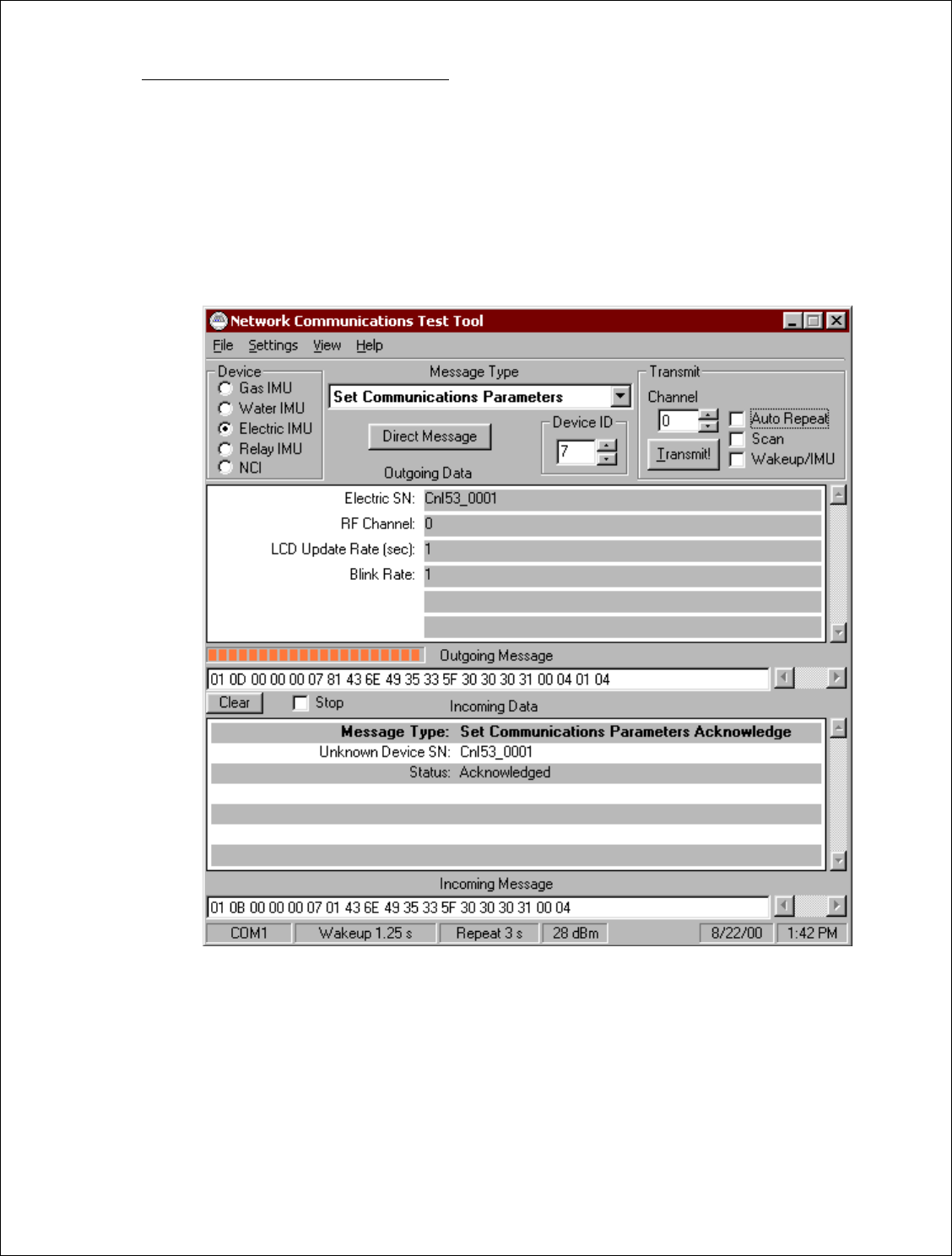
3.3.3. [Set Communication Parameters]
RF CHANNEL = INITIAL CHANNEL
LCD UPDATE RATE = 1
BLINK RATE = 1
Press “TRANMIT”
Make sure to obtain a “Acknowledgement Message “ reply from Incoming Data
Pass__Fail___
FIGURE 5
Document Type: Test Procedure
Equipment Name: Innovatec C and I Electric
Author: Dithien V. Ho, RF Design Engineer.
Page 13 of 24
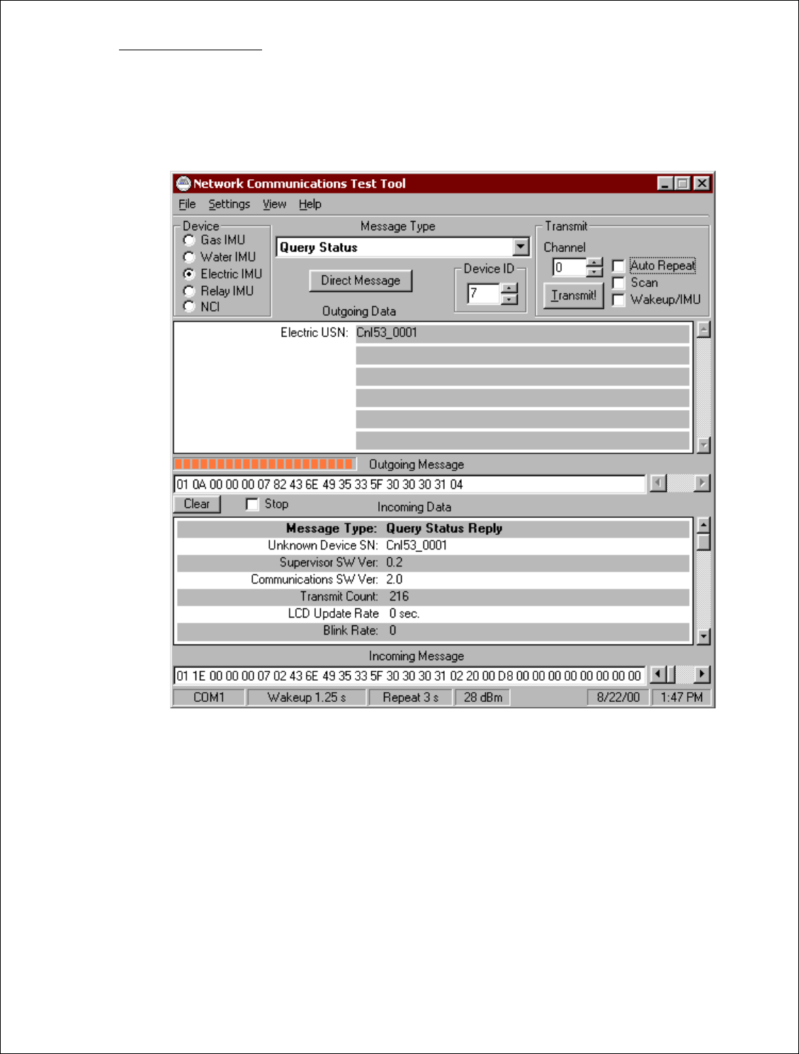
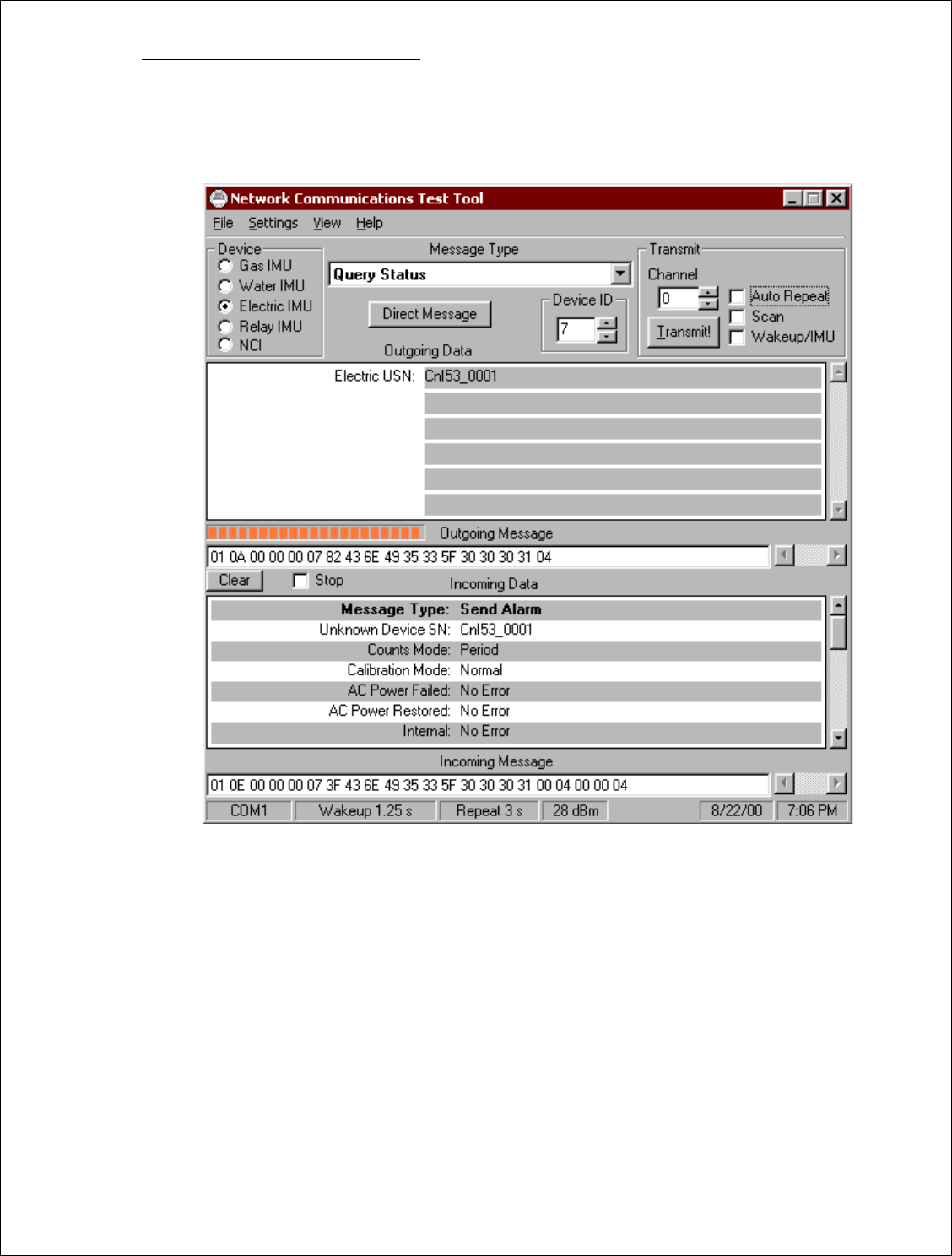
3.3.4. [Query Status]
Select “Query Status for Message Type” then press “Transmit”
Make sure to obtain a reply from Incoming Data
Pass__Fail___
FIGURE 6
Document Type: Test Procedure
Equipment Name: Innovatec C and I Electric
Author: Dithien V. Ho, RF Design Engineer.
Page 14 of 24
4. Final Assembly Test
The following test is to be performed after the PCA Assembly has been tested and install into appropriate Relay
housing unit.
4.1. General Test
Repeat step 3.3.2. and step 3.3.3., if necessary.
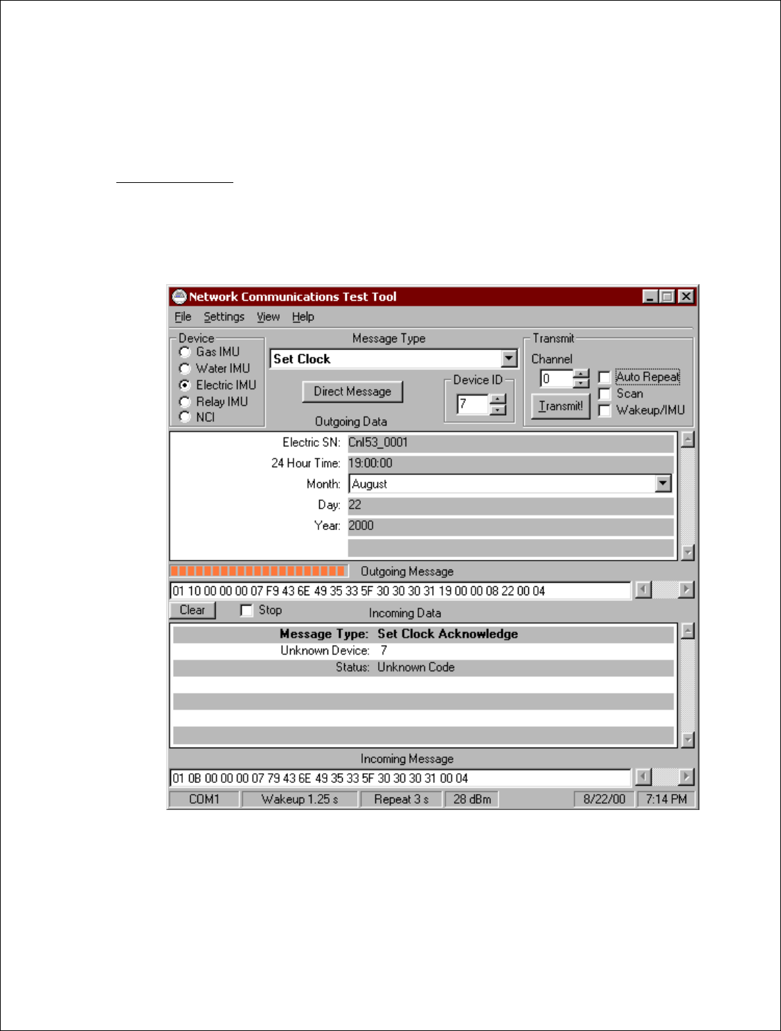
4.1.1. [Set Clock]
Select “Set Clock” message, enter the applicable data then press “Transmit”
Observe “Acknowledged Message “ reply in Incoming Data (See Figure 7)
Pass__Fail__
FIGURE 7
Document Type: Test Procedure
Equipment Name: Innovatec C and I Electric
Author: Dithien V. Ho, RF Design Engineer.
Page 15 of 24
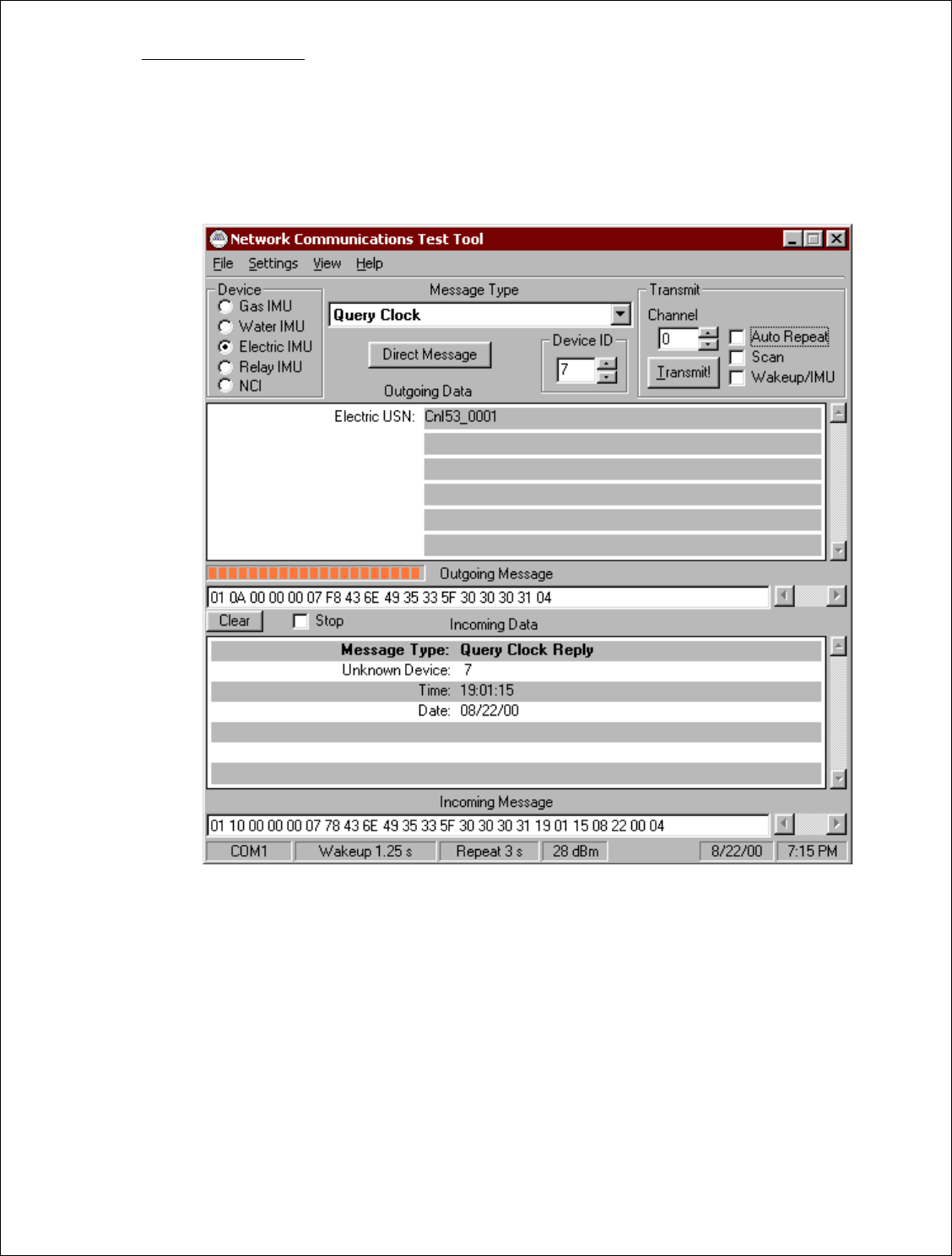
4.1.2. [Query Clock]
Select “Query Clock” message, enter the appropriate Relay Serial Number,
and press “Transmit”
Observe “Acknowledged Message” reply in the Incoming Data fields (See Figure 8)
Verify Calendar and Clock settings.
Pass__Fail__
FIGURE 8
Document Type: Test Procedure
Equipment Name: Innovatec C and I Electric
Author: Dithien V. Ho, RF Design Engineer.
Page 16 of 24
4.2. Alarms Test:
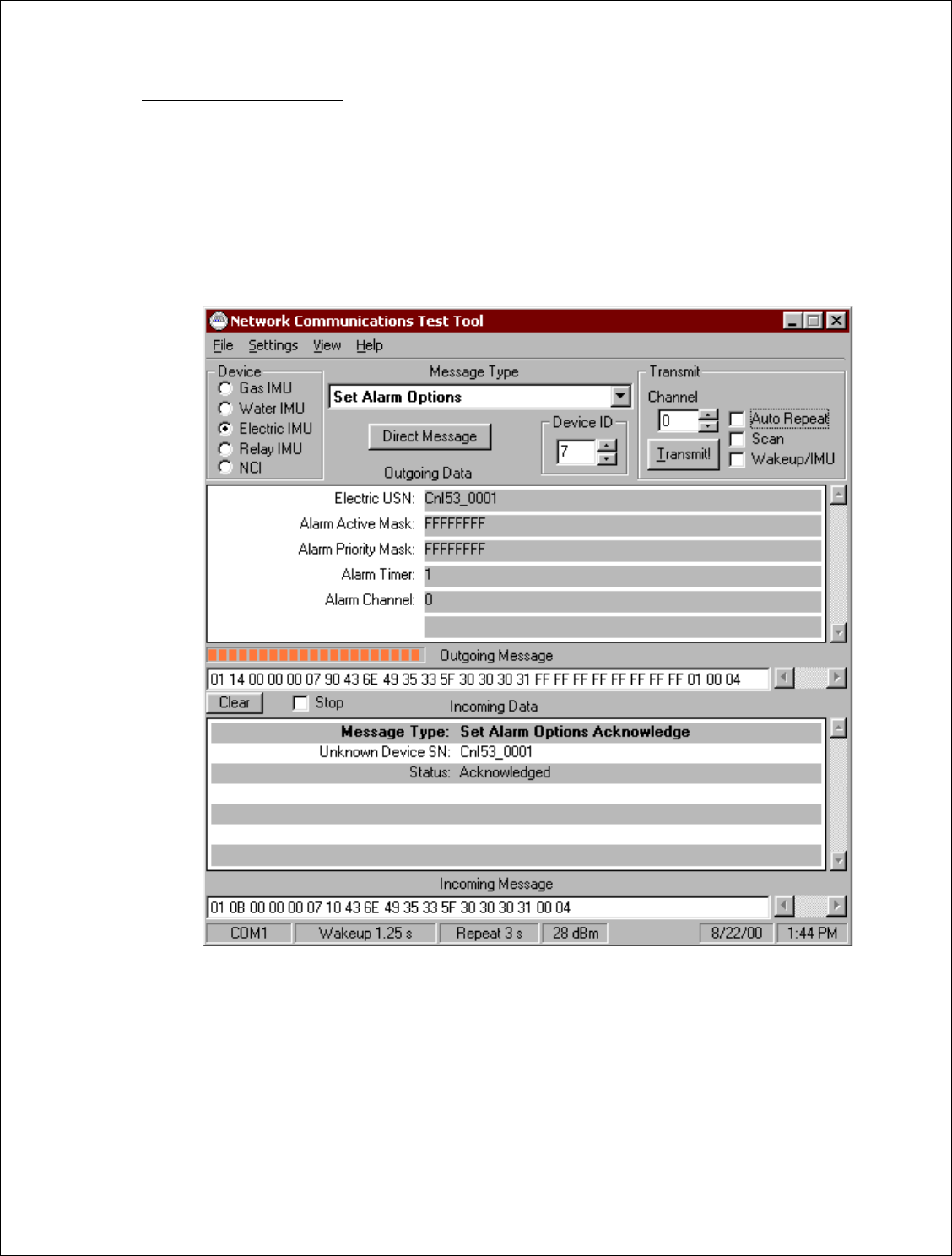
4.2.1. [Set Alarm Option]
Electric USN = UUT Serial Number
Set Alarm Active Mask = FFFFFFFF (8)
Set Alarm Priority Mask = FFFFFFFF (8)
Alarm Timer = 1 (Optional)
Alarm Channel = INITIAL CHANNEL (Same as Communications Channel)
Pass__Fail___
FIGURE 9
Document Type: Test Procedure
Equipment Name: Innovatec C and I Electric
Author: Dithien V. Ho, RF Design Engineer.
Page 17 of 24
4.2.2. Tamper Alarm Function Test:
Open the C&I UUT cover (Will release the Tamper Switch)
Verify the Tamper Alarm message is sent
Pass__Fail___
FIGURE 10

Document Type: Test Procedure
Equipment Name: Innovatec C and I Electric
Author: Dithien V. Ho, RF Design Engineer.
Page 18 of 24
4.2.3. Power Failure Alarm Function Test:
Disconnect the ac power to the C&I UUT; verify the Power Failure Alarm Message is sent
Pass__Fail___
FIGURE 11
Document Type: Test Procedure
Equipment Name: Innovatec C and I Electric
Author: Dithien V. Ho, RF Design Engineer.
Page 19 of 24
4.2.4. Power Restore Alarm Function Test
Re-connect the ac power to the C&I UUT; verify the Power Failure Restore Status Report
Pass__Fail___
FIGURE 12

Document Type: Test Procedure
Equipment Name: Innovatec C and I Electric
Author: Dithien V. Ho, RF Design Engineer.
Page 20 of 24
4.2.5. Disabling Alarm Transmit Function Test
Repeat step 4.2.1 and set “Alarm Active Mask” and “Alarm priority Mask” to 0:
Electric USN = UUT Serial Number
Set Alarm Active Mask = 00000000 (8)
Set Alarm Priority Mask = 00000000 (8)
Alarm Timer = 1 (Optional)
Alarm Channel = INITIAL CHANNEL (Same as Communications Channel)
4.2.5.1.Activate “Tamper” switch; observe for none alarm send message transmits.
4.2.5.2. Disconnect AC power; observe for none alarm send message transmits.
4.2.5.3. Reconnect AC powers; observe for none alarm send message transmits.
Pass__Fail___
FIGURE 13
Document Type: Test Procedure
Equipment Name: Innovatec C and I Electric
Author: Dithien V. Ho, RF Design Engineer.
Page 21 of 24
4.3. Actuators Test:
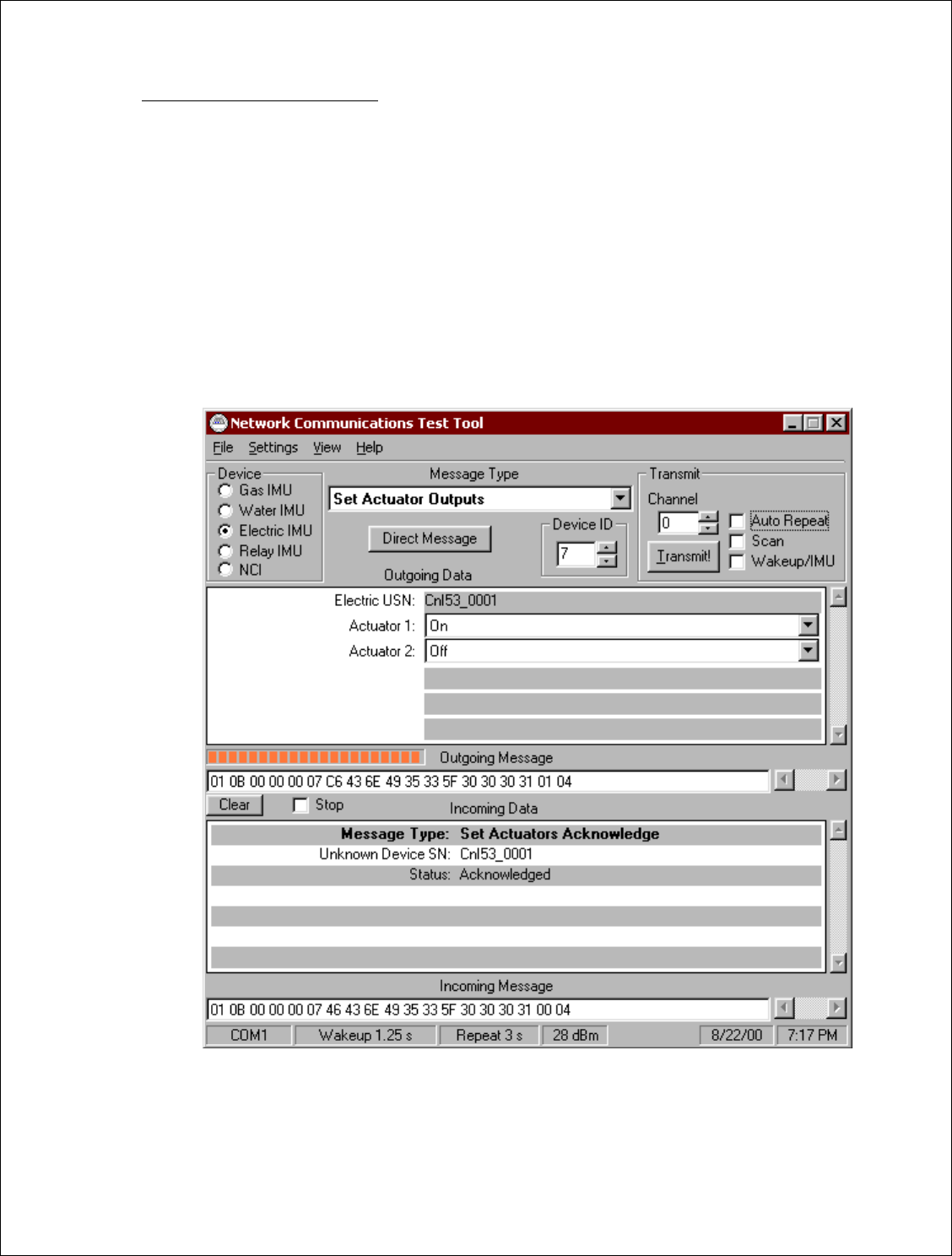
4.3.5. [Set Actuator 1 Output]
Type in Electric USN = C&I UUT Serial Number
Set Actuator 1 = ON
Set Actuator 2 = OFF
Press “Transmit”
Make sure to obtain a “Acknowledgement Message “ reply from Incoming Data
Use DVM to verify between Pin 1, J10 (Actuator 1 Output) and Pin 3, J10 (Actuator 1) Common
are “Closed”
Use DVM to verify between Pin 2, J10 (Actuator 2 Output) and Pin 4, J10 (Actuator 2) Common
are “Open”
Pass__Fail___
FIGURE 13
Document Type: Test Procedure
Equipment Name: Innovatec C and I Electric
Author: Dithien V. Ho, RF Design Engineer.
Page 22 of 24
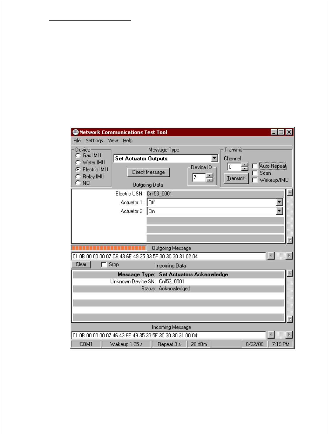
4.3.6. [Set Actuator 2 Output]
Type in Electric USN = C&I UUT Serial Number
Set Actuator 1 = OFF
Set Actuator 2 = ON
Press “Transmit”
Make sure to obtain a “Acknowledgement Message “ reply from Incoming Data
Use DVM to verify between Pin 1, J10 (Actuator 1 Output) and Pin 3, J10 (Actuator 1) Common
are “Open”
Use DVM to verify between Pin 2, J10 (Actuator 2 Output) and Pin 4, J10 (Actuator 2) Common
are “Close”
Pass__Fail___
FIGURE 14
Document Type: Test Procedure
Equipment Name: Innovatec C and I Electric
Author: Dithien V. Ho, RF Design Engineer.
Page 23 of 24
4.4. Battery Power Sustain Test:
4.4.5. Disconnect the ac power to the C&I UUT
4.4.6. [Query Serial Number]
Verify to obtain the correct Serial Number report for the C&I UUT.
Pass__Fail___
FIGURE 15

Document Type: Test Procedure
Equipment Name: Innovatec C and I Electric
Author: Dithien V. Ho, RF Design Engineer.
Page 24 of 24
5. Shipping Preparation:
• IMPORTANT!:
Make sure to disconnect the hook-up wire from the Battery charger to the
Positive (+) terminal of the battery!
Battery Disconnect Check: Initial_____
• Mechanical Inspection:
Inspect all harware, screw and nut, wires and cables for propper fitting.
• Cosmetic Inspection:
Inspect for cosmetic defective.