Itron IPDL-WT1 WiFi-Enabled Digital Control Unit User Manual Final Sent to Pravin

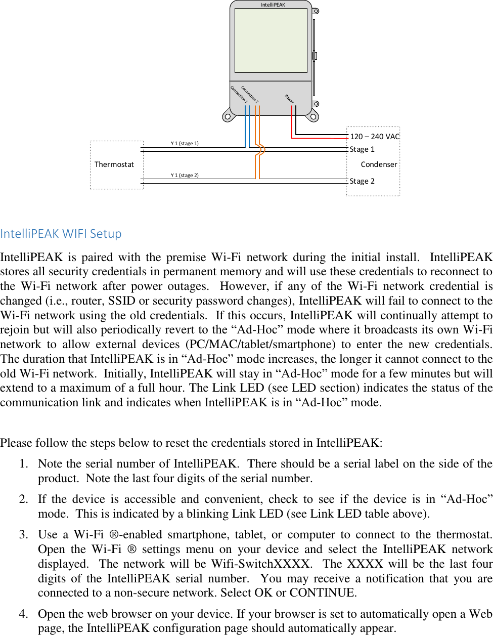
Itron Distributed Energy Management, Inc. WiFi-Enabled Digital Control Unit Final Sent to Pravin

User Manual

IntelliPEAK DirectLink WiFi  IntelliPEAK DirectLink Applications Guide IntelliPEAK DirectLink can be installed to control the following loads.   Description  HVAC Yes Water Heater Yes Pool Pump Yes Refrigeration Yes  It  requires  connection  to  line  power  and  must  be  installed  by  a  trained  and  experienced technician.    Do  not  under  any  circumstances  open  the  door  and  touch  any  components inside, as line voltage (120 – 240 VAC) is present.  You could damage this product or cause a hazardous condition if you fail to follow these instructions.  Need Help?  For assistance with this product, please visit http://www.comverge.com or call?  HVAC For HVAC, IntelliPEAK DirectLink is typically installed outside, near your compressor.  It is wired  to  the  same  power  source  as  the  compressor  and  relays  inside  IntelliPEAK  will intelligently reduce the compressor run time during a control event to reduce the demand on the electrical grid during event periods.   Relay(s) inside the device will interrupt the control signal from the thermostat to the compressor and will only disable the compressor periodically during a control event.  The indoor fan will continue to run during this time.  The indoor temperature is expected to rise a few degrees during the event, depending on the amount of insulation in the premise.
CondenserIntelliPEAKDisconnect  Water Heater/Pool Pump/Refrigeration For controlling electric water heaters, pool pumps, or refrigeration, IntelliPEAK DirectLink is typically installed near the appliance or power source and interrupts the power to the appliance for control.  During control event periods, IntelliPEAK will open the power connection to the appliance  to  reduce  the  demand  on  the  electrical  grid.    It  is  expected  that  the  load  will  be disabled for the entire duration of the control period.  LED and What Do They Indicate IntelliPEAK contains up to four1 LED (Light Emitting Diodes) underneath a clear window in front of the unit.  These LEDs show the operation of the IntelliPEAK device as shown below:    LED Indicators                                                             1 IntelliPEAK DirectLink used in water heater/pool pump/refrigeration contain only one (1) relay and has three (3) LEDs – Relay2 LED is not present. Shows status of communication link Used by installer Light on when a control event is active and relay is open Light on when a control event is active and relay is open
Link LED The Link LED is used to indicate the status of the communication link.  When it stays on solid, it indicates  good  end-to-end  communication  with  the  controlling  software  system.    If  any  link along the communication chain is lost, the LED will blink at different patterns as shown below:  Link LED Status Off Client mode - no network connection 0.5 second blink Ad-hoc mode – IntelliPEAK is creating its own Wi-Fi network to allow entry of credentials 1 second on, 3 second off blink Client mode - Wi-Fi network connected, waiting for internet connection 3 seconds on, 1 second off blink Client mode – Wi-Fi/internet network connected, but not connected to controlling software Solid On Client mode - Cellular/internet/software connection OK  Test LED The Test LED is used by the installer during installation.  When the device is first powered up, the Test LED will flash either one or two times to indicate a cold or warm start respectively.  The Test LED can also be manually toggled by the installer to test end-to-end communication with the software using his test tool.  In normal operation, this LED should be off.  Relay LED The relay LED(s) is used to indicate whether the appliance is prohibited from running during a control  event.    It  is  turned  on  whenever  the  appliance  (HVAC,  water  heater,  pump  or refrigeration) is being controlled and is prohibited from running. When used with HVAC2, the compressor  is  controlled  and  released  periodically.    This  allows  some  amount  of cooling/dehumidification  as  well  as  air  circulation  during  the  control  period  to  minimize customer discomfort.  This LED will turn on during the times when the HVAC is turned off.                                                             2 HVAC may have multiple compressor stages.  In these installations, each relay is used to control each stage of the compressor and both relays will open at the same time to prohibit both stages of the compressor from running during a control event.
Cold Load Pickup IntelliPEAK  DirectLink  is  designed  to  prohibit  the  connected  load  from  coming  back  on immediately after a power outage.  This ensures that the electrical grid has time to recover from the transient  condition  that caused  the  outage.    When  the  Cold  Load Pickup  is  activated,  the Relay  LEDs will  turn  on and  the  relays  are  open  to  prohibit  the  load  from  running.    This  is normal.  After the Cold Load Pickup timer expires, the connected appliance is allowed to resume its normal operation.  The default Cold Load Pickup time delay is:  • HVAC – 90 seconds • Water heater/pool pump/refrigeration – 0 seconds  Hardware Error Reporting If the IntelliPEAK hardware senses an error that prevents normal operation of the switch, then all LED’s  will  flash  as  an  indicator  of  this  condition.  If  this  happens  repeatedly, then the switch should be replaced.  IntelliPEAK Wiring • 2 Single Stage Condenser Units and a Single IntelliPEAK  IntelliPEAKThermostat 1 Condenser 1Condenser 2Thermostat 2120 – 240 VACY 1Y 1  • 1 Two Stage Condenser Unit and a Single IntelliPEAK
IntelliPEAKThermostat Condenser 120 – 240 VACY 1  (stage 1)Y 1  (stage 2)Stage 1Stage 2   IntelliPEAK WIFI Setup IntelliPEAK is  paired with the  premise Wi-Fi network  during the  initial  install.   IntelliPEAK stores all security credentials in permanent memory and will use these credentials to reconnect to the  Wi-Fi  network  after  power outages.    However, if  any of  the  Wi-Fi  network  credential  is changed (i.e., router, SSID or security password changes), IntelliPEAK will fail to connect to the Wi-Fi network using the old credentials.  If this occurs, IntelliPEAK will continually attempt to rejoin but will also periodically revert to the “Ad-Hoc” mode where it broadcasts its own Wi-Fi network  to  allow  external  devices  (PC/MAC/tablet/smartphone)  to  enter  the  new  credentials.  The duration that IntelliPEAK is in “Ad-Hoc” mode increases, the longer it cannot connect to the old Wi-Fi network.  Initially, IntelliPEAK will stay in “Ad-Hoc” mode for a few minutes but will extend to a maximum of a full hour. The Link LED (see LED section) indicates the status of the communication link and indicates when IntelliPEAK is in “Ad-Hoc” mode.  Please follow the steps below to reset the credentials stored in IntelliPEAK: 1. Note the serial number of IntelliPEAK.  There should be a serial label on the side of the product.  Note the last four digits of the serial number. 2. If  the  device  is  accessible  and  convenient,  check  to  see  if  the  device  is  in  “Ad-Hoc” mode.  This is indicated by a blinking Link LED (see Link LED table above). 3. Use  a  Wi-Fi  ®-enabled  smartphone,  tablet,  or  computer  to  connect  to  the  thermostat. Open  the  Wi-Fi  ®  settings  menu  on  your  device  and  select  the  IntelliPEAK  network displayed.  The network will be Wifi-SwitchXXXX.  The XXXX will be the last four digits of  the  IntelliPEAK  serial  number.  You  may receive  a  notification  that  you are connected to a non-secure network. Select OK or CONTINUE. 4. Open the web browser on your device. If your browser is set to automatically open a Web page, the IntelliPEAK configuration page should automatically appear.
5. If the settings page does not appear after a few seconds, type “DirectLink/settings” in the address bar, then press ENTER.    6. Use the pull-down on the settings page to select your user network name  7. If your wireless Internet router is set to hide the network name or your network is not listed in the pull-down, click on the link “Click Here If your WIFI network is not listed” to display the manual settings page.
  8. Manually enter the WiFi Network Name (SSID), select the security type from the drop down menu, and enter the security key.
  9. Enter the network password for your network in the Security Key field:
10. Once all fields are filled in correctly, click on the Save button.  11. The settings page will now show an overview of the settings you entered. If all settings are correct, click on Apply. If you need to correct any settings, click on Cancel. 12. After clicking Apply, a Configuration Complete message will be displayed.  Close your browser to complete the network configuration.   13. Steady state yellow LED will signify the successful completion of the WIFI setup and network connection. 14. Restore  your  Wi-Fi-enabled  smartphone,  tablet,  or  computer  to  connect  to  the  normal network.
 Specifications  Power Input 120VAC – 240VAC auto-ranging Power Consumption Less than 12 VA Operating Condition -35° to +85° C, 0% - 95% humidity (non-condensing) Regulatory FCC part 15; UL 916  Relay Rating/Cycles  2 Function (2F): 24VAC, 2 Amp 1 Function (1F): 240VAC, 30 Amp Resistive Electrical Endurance: 250,000 cycles at rated worst-case loads Mechanical Endurance: 10 million cycles at rated loads  Packaging Injection molded, high-impact poly-carbonate, weather resistant for outdoor installation  Note: Changes or modifications not expressly approved by the party responsible for compliance could void the user's authority to operate the equipment

Navigation menu