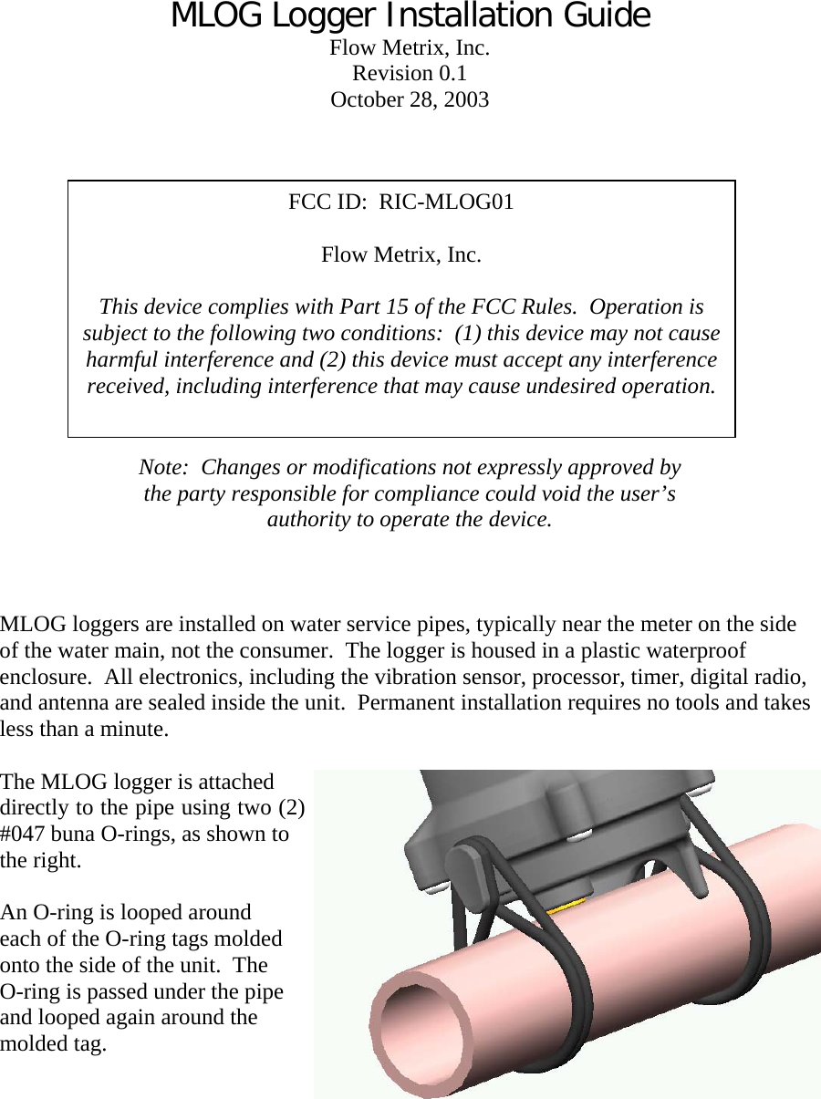
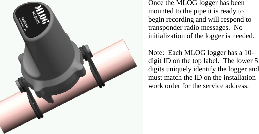
Itron MLOG01 MLOG User Manual MLOG Logger Installation Guide

Itron, Inc. MLOG MLOG Logger Installation Guide

Users Manual

MLOG Logger Installation Guide Flow Metrix, Inc. Revision 0.1 October 28, 2003    FCC ID:  RIC-MLOG01    Flow Metrix, Inc.  This device complies with Part 15 of the FCC Rules.  Operation is subject to the following two conditions:  (1) this device may not cause harmful interference and (2) this device must accept any interference received, including interference that may cause undesired operation. Note:  Changes or modifications not expressly approved by the party responsible for compliance could void the user’s authority to operate the device.    MLOG loggers are installed on water service pipes, typically near the meter on the side of the water main, not the consumer.  The logger is housed in a plastic waterproof enclosure.  All electronics, including the vibration sensor, processor, timer, digital radio, and antenna are sealed inside the unit.  Permanent installation requires no tools and takes less than a minute.  The MLOG logger is attached directly to the pipe using two (2) #047 buna O-rings, as shown to the right.  An O-ring is looped around each of the O-ring tags molded onto the side of the unit.  The O-ring is passed under the pipe and looped again around the molded tag.
         Once the MLOG logger has been mounted to the pipe it is ready to begin recording and will respond to transponder radio messages.  No initialization of the logger is needed.  Note:  Each MLOG logger has a 10-digit ID on the top label.  The lower 5 digits uniquely identify the logger amust match the ID on the instalwork order for the service address. nd lation

Navigation menu