Itron ORRN Routing node (Gateway) for part of an Automatic Meter Reading network User Manual ERT Gateway Installation Guide
Itron, Inc. Routing node (Gateway) for part of an Automatic Meter Reading network ERT Gateway Installation Guide
Itron >
Users Manual

OpenWay® Riva Routing Node
ERT Gateway Installation Guide
Technical
Communications
knowledge to shape your future
Identification
OpenWay® Riva Routing Node-ERT Gateway Installation Guide
14 December 2017
TDC-1744-000
Copyright
© 2017 Itron, Inc. All rights reserved.
Confidentiality Notice
The information contained herein is proprietary and confidential and is being provided
subject to the condition that (i) it be held in confidence except to the extent required
otherwise by law and (ii) it will be used only for the purposes described herein. Any third
party that is given access to this information shall be similarly bound in writing.
Trademark Notice
Itron is a registered trademark of Itron, Inc.
All other product names and logos in this documentation are used for identification purposes
only and may be trademarks or registered trademarks of their respective companies.
Suggestions
For more information about Itron or Itron products, see www.itron.com.
If you have questions or comments about the software or hardware product, contact Itron
Technical Support Services.
Contact
• Email: support@itron.com
• Internet: support.itron.com
• Telephone Itron Technical Support North America: 1-877-487-6602
For technical support contact information by region, go to www.itron.com and select your
country and language.

Contents
Chapter 1 Important Safety and Compliance Information.............................. 1
USA, FCC Part compliance.................................................................................................................................. 1
Electromagnetic compatibility...............................................................................................................................2
Chapter 2 Getting Started: OpenWay® Riva Routing Node-ERT Gateway.... 3
ERT Gateway related documents......................................................................................................................... 3
Installation location information............................................................................................................................ 4
ERT Gateway components................................................................................................................................... 4
ERT Gateway housing................................................................................................................................5
ERT Gateway antennas..............................................................................................................................6
Chapter 3 Planning an ERT Gateway Installation.............................................7
Installation proles................................................................................................................................................ 7
Siting the ERT Gateway........................................................................................................................................ 7
Propagation study for the ERT Gateway installation site ..........................................................................8
AC power requirements............................................................................................................................. 8
AC mains power....................................................................................................................................................8
Mounting hardware requirements......................................................................................................................... 9
Chapter 4 Installing the ERT Gateway.............................................................10
Installation overview............................................................................................................................................10
Mounting the ERT Gateway antennas................................................................................................................ 10
Attaching the standard 915MHz ERT antenna.........................................................................................10
Attaching the backhaul antenna.............................................................................................................. 12
Mounting the ERT Gateway................................................................................................................................ 13
Mounting hardware.................................................................................................................................. 13
Mounting the ERT Gateway on a pipe..................................................................................................... 15
Mounting the ERT Gateway on a pole..................................................................................................... 16
Mounting the ERT Gateway on a davit arm............................................................................................. 16
Connecting the ground wire.....................................................................................................................17
Connecting the ERT Gateway power.......................................................................................................17
Connecting the power cable.............................................................................................................18
ERT Gateway wiring diagram...................................................................................................................18
Chapter 5 OpenWay Riva Routing Node Communications Software...........20
Appendix A ERT Gateway Specifications........................................................21
Dimensions and weight.......................................................................................................................................21
Antenna specications........................................................................................................................................21
Environmental specications.............................................................................................................................. 22
Transmitter.......................................................................................................................................................... 22
ERT Gateway power operating range.................................................................................................................22
ERT Gateway Installation Guide TDC-1744-000 iii
Proprietary and Confidential

Chapter 1 Important Safety and Compliance
Information
This section provides important information for your safety and product compliance.
USA, FCC Part compliance
This device complies with Part 15 of the FCC Rules. These limits are designed to provide
reasonable protection against harmful interference in a residential installation.
Operation is subject to the following two conditions:
• This device may not cause harmful interference.
• This device must accept any interference that may cause undesirable operation.
This device must be installed to provide a separation distance of at least 20 centimeters (7.9
inches) from all persons to be compliant with regulatory RF exposure.
USA, FCC Class B-Part 15
This equipment has been tested and found to comply with the limits for a Class B digital
device, pursuant to Part 15 of the FCC Rules. These limits are designed to provide
reasonable protection against harmful interference in a residential installation. This
equipment generates, uses, and can radiate radio frequency energy and, if not installed and
used in accordance with the instructions, may cause harmful interference to radio
communications. However, there is no guarantee that interference will not occur in a
particular installation. If this equipment does cause harmful interference to radio or television
reception, which can be determined by turning the equipment off and on, the user is
encouraged to try to correct the interference by one or more of the following measures:
• Reorient or relocate the receiving antenna.
• Increase the separation between the equipment and receiver.
• Connect the equipment into an outlet on a circuit different from that to which the receiver
is connected.
• Consult the dealer or an experienced radio or TV technician for help.
Modifications and Repairs
To ensure system performance, this device and antenna shall not be changed or modified
without the express approval of Itron. Per FCC rules, unapproved modifications or operation
beyond or in conflict with these instructions for use could void the user's authority to operate
the equipment.
ERT Gateway Installation Guide TDC-1744-000 1
Proprietary and Confidential

Electromagnetic compatibility
Caution: Use only approved accessories with this equipment. All cables must be
high quality, shielded, and correctly terminated. Unapproved modifications or
operation beyond or in conflict with these use instructions may void the authority's
authorization to operate the equipment.
Important Safety and Compliance Information
ERT Gateway Installation Guide TDC-1744-000 2
Proprietary and Confidential
Chapter 2 Getting Started: OpenWay® Riva
Routing Node-ERT Gateway
The OpenWay Riva Routing Node-ERT Gateway provides a unified means of reading Itron
100G series and 100W series devices over an IPv6 network. The OpenWay Riva Routing
Node ERT Gateway can be deployed in one of two network configurations designated in the
firmware. The ERT Gateway Star operates over a Star network to collect the Itron 100
Series gas and water ERT module reads.
Note: The ERT Gateway does not support 100W+ Series modules operating in Extended
Range Mode (Geo Mode).
The ERT Gateway Mesh (future release) will operate over a Mesh network.
The network configuration is selected on the specification form at the time the system is
ordered.
The ERT Gateway communicates directly with the Connected Grid Router (CGR). The
gateway utilizes RF links with optimized modulation rates. The CGR then transmits the data
to the OpenWay Operations Center (a part of the head-end system) over the utility's
backhaul communication solution. The ERT Gateway's flexible design provides installation
options for a variety of wall-mounted or pole-mounted locations. This flexibility provides
optimal communication effectiveness and range and minimizes installation costs.
Important: Installation must be completed by professional installers to ensure trouble-free
operation of the Itron OpenWay system. Follow these product installation instructions to
ensure proper operation of your OpenWay Riva Routing Node ERT Gateway Star.
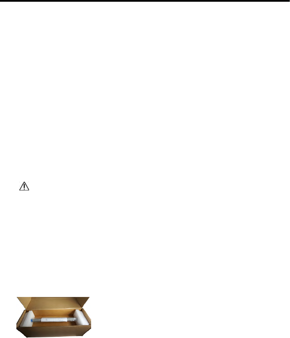
Use the ERT Gateway shipping packaging to transport the ERT Gateway. The shipping
materials protect the ERT Gateway from damage.
ERT Gateway related documents
The listed documents provide additional information for ordering and working with the
OpenWay Riva Routing Node ERT Gateway Star.
Document Itron part number
OpenWay Riva Routing Node-ERT Gateway Ordering Guide PUB-1306-001
OpenWay Collection Manager Installation and Configuration Guide TDC-1675-XXX
ERT Gateway Installation Guide TDC-1744-000 3
Proprietary and Confidential
Document Itron part number
OpenWay® Operations Center Performance Manager Integration Guide
Integration Guide
TDC-1718-XXX
Installation location information
The ERT Gateway is designed for the listed installation locations:
• Wood, concrete, or metal utility pole
• Wall (indoor or outdoor)
• Pipe or mast (between 2 and 3.5" in diameter)
• Roof
Note: Roof installation requires a 3rd-party, non-penetrating mounting kit (for example,
Tessco #461587)
• Other vertical structures
Integrated mounting and coupling brackets secure the device in high winds and under
heavy ice loads. Consult a professional engineer with concerns about your ERT Gateway
mounting location.
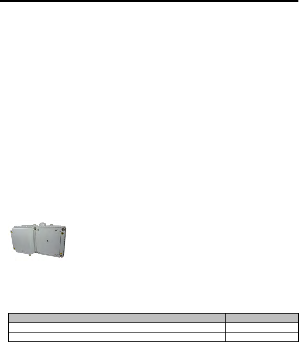
The ERT Gateway consists of several components in a single, weatherproof device.
Electrical components are encased in a plastic enclosure that provides optimum safety for
the installer.
Warning: In accordance with FCC rules, unapproved modifications or operation
beyond or in conflict with these use instructions could void the user's authority to
operate the equipment. Only authorized Itron personnel may open the ERT
Gateway. Unauthorized access or modifications to the ERT Gateway will void the
warranty.
ERT Gateway components
The ERT Gateway (Star) has two antennas that are mounted directly on the gateway
housing.
• Backhaul antenna
• ERT antenna
Since the ERT Gateway can be installed in outdoor environments, each component of the
gateway is weather-tight and able to withstand wind speeds in excess of 100 miles per hour.
Note: Review the ERT Gateway Ordering Guide (PUB-1306-001) for specific part numbers
and component options to determine the ERT Gateway configuration.
Getting Started: OpenWay® Riva Routing Node-ERT Gateway
ERT Gateway Installation Guide TDC-1744-000 4
Proprietary and Confidential
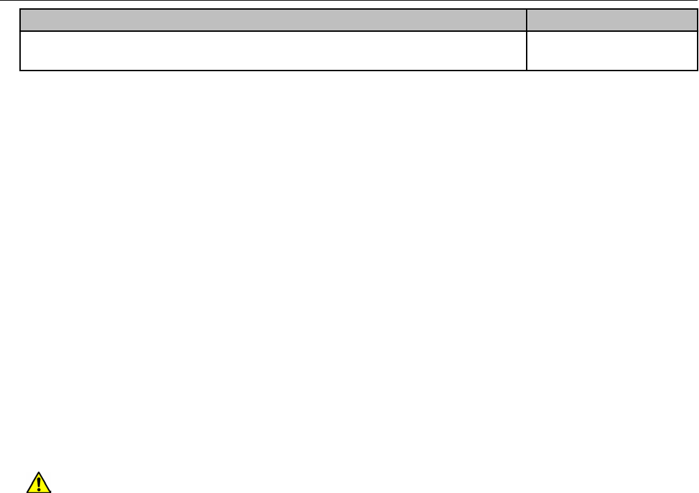
ERT Gateway housing
The ERT Gateway housing contains the electronic components and radio boards. The radio
antennas are included with the gateway and are directly mounted to the housing.
Caution: Only authorized Itron personnel may open this device. Unauthorized
access or modifications to this product voids the warranty. Per FCC rules,
unapproved modifications or operation beyond or in conflict with the installation
instructions in this guide could void the user's authority to operate the equipment.
Designator Component Description
1 ERT Gateway The ERT Gateway processes data received through the antennas and relays it to the
OpenWay Operations Center (OWOC). Only authorized Itron personnel may open this
product housing.
2 ERT antenna A 915MHz antenna that receives messages from the 100 series ERT modules in the
network. The connection for this antenna is type N female.
3 ERT Gateway
label
The label displays the identification number, model number, and other associated
gateway information.
4 Power
connector
The power connector supplies power to the ERT Gateway. A three-pin cable connects
the ERT Gateway to the AC mains power supply.
5 Backhaul
antenna
A 915MHz antenna that provides a connection to the STAR or MESH network. The
connection for this antenna is a type N female.
6 Ground lug The ground lug is optional on the ERT Gateway and is provided for utilities that require a
separate earth ground.
Note: When the ERT Gateway is powered with the light pole/photo sensor adapter, there
is no ground connection. Use the ground lug in this configuration.
7 LED Status
indicator The status indicator displays the current operational status of the ERT Gateway.
The LED indicator is located on the bottom of the housing.
• Unpowered (off)
• Initializing (green blink)
• Running (green)
• Error (yellow)
The LED is configurable for the following display modes:
• None (no light)
• Error only
• Normal
Getting Started: OpenWay® Riva Routing Node-ERT Gateway
ERT Gateway Installation Guide TDC-1744-000 5
Proprietary and Confidential
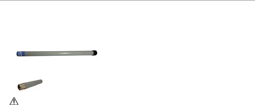
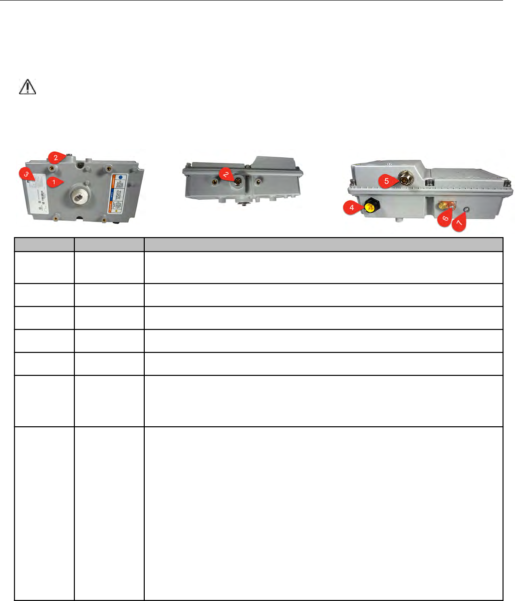
ERT Gateway antennas
The ERT Gateway utilizes two antennas.
•ERT antenna The ERT antenna is a standard, higher gain, vertically polarized antenna
that mounts directly to the top of the ERT Gateway housing.
•Backhaul antenna The backhaul antenna is a standard, lower gain, vertically polarized
antenna that mounts directly to the bottom of the ERT Gateway housing.
Caution: This equipment has been designed and approved per FCC rules to
operate with the antennas listed. The required antenna impedance is 50 ohms. To
reduce potential radio interference to other users, the antenna type and its gain were
chosen so that the equivalent isotropically radiated power (EIRP) is not more than
that permitted for successful communication. Antennas not included in this list and
approved by Itron are strictly prohibited for use with this device. Installing the
OpenWay Riva Routing Node ERT Gateway with an unapproved antenna will void
the product warranty and can void the user's authority to operate this equipment.
Getting Started: OpenWay® Riva Routing Node-ERT Gateway
ERT Gateway Installation Guide TDC-1744-000 6
Proprietary and Confidential
Chapter 3 Planning an ERT Gateway Installation
This chapter describes ERT Gateway installation preparation and planning.
Installation profiles
The ERT Gateway may be installed in a variety of configurations and locations (for more
information, see Installation location information on page 4). Itron identified the following
profiles for ERT Gateway installations.
Location Location description
Utility pole The ERT Gateway is installed on a utility pole. Mount the ERT Gateway at a
maximum height of 25 feet high on the utility pole for optimum reception.
Light pole/
street light
The ERT Gateway is installed on either a light pole or the davit arm of the street
light. Mount the ERT Gateway at a maximum height of 25 feet high on the light
pole/street light for optimum reception.
Pipe or mast The ERT Gateway is secured/installed to a pipe or fence railing (from 2 to 3.5
inches in diameter). Mount the ERT Gateway at a maximum height of 25 feet high
on the pipe or fence for optimum reception.
Siting the ERT Gateway
ERT Gateways can be installed in the field on a variety of surfaces. The listed surfaces are
examples of surfaces that support the ERT Gateway.
• Wooden or metal walls
• Metal pipes
• Fence railings
• Utility poles
In determining the ERT Gateway placement, observe the following primary considerations
as placement best practices.
• For optimum RF reception.
• In a location where there is a power connection.
• On a structure on in a location that can physically support the weight of the ERT Gateway
(and its mounting hardware).
Caution: Always get permission to install the ERT Gateway at the selected site prior
to installation. If you have questions or need help, contact Itron Support.
ERT Gateway Installation Guide TDC-1744-000 7
Proprietary and Confidential
Propagation study for the ERT Gateway installation site
Prior to the ERT Gateway field installation, contact Itron. Itron performs these tasks during
the propagation study to determine the exact ERT Gateway installation location and the best
mounting surface.
• Evaluate the quantity and types of network endpoints.
• Assess the environmental and geographical considerations for the ERT Gateway
installation.
• Optimize the ERT Gateway placement within the network to get the best possible
reception.
• Assess the physical and structural implications of the selected mounting surface.
This iterative process may be repeated as the final installation parameters are determined.
AC power requirements
The ERT Gateway requires an 102-264 VAC source defined as a minimum 15-amp branch
circuit (or larger). The ERT Gateway must be protected by a certified branch circuit breaker.
Warning: Do not connect the ERT Gateway to a circuit protected by a GFCI breaker.
The wiring must be sized in accordance with the National Electrical Code, ANSI/NFPA 70
and, where applicable, the Canadian Electrical Code, Part I, CSA C22.1 or the prevailing
local code.
AC mains power
The AC mains wiring to the ERT Gateway utilizes a three-conductor cable. Terminate the
cable with either a NEMA L5-15 (125V, 15A), NEMA L6-15 (250V, 15A) locking plug, or by
directly splicing to the secondary power to meet electrical codes.
The ERT Gateway must be powered by an 102-264 VAC source defined as a maximum 15-
amp branch circuit.
Warning: Verify the 102-264 VAC power source (15-amp branch circuit). Do not
connect the ERT Gateway to the wrong voltage during installation. Supplying the
wrong voltage could result in a fire hazard!
The ERT Gateway must be protected by a certified branch circuit breaker. Do not connect
the ERT Gateway to a circuit protected by a GFCI breaker. Size the wiring in accordance
with the National Electrical Code, ANSI/NFPA 70, and where applicable, the Canadian
Electrical Code, Part 1 CSA C22.1 or the prevailing local code. Power wiring on the Itron-
supplied power cable follows conventional color coding for AC wiring: green (ground), white
(neutral), and black (hot).
Planning an ERT Gateway Installation
ERT Gateway Installation Guide TDC-1744-000 8
Proprietary and Confidential
Warning: Securely mount the ERT Gateway before connecting the dedicated AC
mains power source. The ERT Gateway must be grounded using either the ground
wire in the three-conductor cable or the grounding lug on the bottom of the ERT
Gateway. For installations that use the photocell adapter, the grounding lug must be
used to ground the ERT Gateway.
Mounting hardware requirements
Mounting hardware requirements are based on the installation location and your system
configuration. The installer must supply the following mounting hardware to properly attach
the ERT Gateway to the mounting surface.
Caution: Each installation is unique. You must ensure that the mounting hardware
securely supports the ERT Gateway. The ERT Gateway without the mounting
hardware weighs pounds. Itron recommends that you consult a qualified engineer to
verify load requirements and safety issues. Installers must comply with local codes
when the ERT Gateway is installed.
Profile Mounting surface Suggested hardware/sizing
Utility pole Wood or steel pole High-strength stainless steel straps
Light pole Steel light pole High-strength stainless steel straps
Pipe 2.5" to 3.5"
galvanized steel
pipe
Two pipe mount brackets for pipes up to 3.5" in
diameter. Pipe mount brackets are available from Itron
(part number FAB-0192-001). Two brackets are
required for each ERT Gateway.
Planning an ERT Gateway Installation
ERT Gateway Installation Guide TDC-1744-000 9
Proprietary and Confidential
Chapter 4 Installing the ERT Gateway
This chapter provides the Itron-approved instructions to install an ERT Gateway in the field.
The ERT Gateway can be installed in a variety of locations. This installation profile uses an
AC mains power.
Note: Before the ERT Gateway installation, ensure that the selected location will support the
weight of the gateway and its mounting hardware. Engage a registered engineer to conduct
a structural analysis of the installation location prior to the installation. Itron is not
responsible for improper installation or for installation at a site that cannot adequately
support the ERT Gateway.
Installation overview
This ERT Gateway installation profile describes installation mounting the gateway to a 2-
inch vertical pipe. The ERT Gateway power source is a 110V AC mains supply. During
installation, the listed tasks are completed.
1. Attaching the 915MHz ERT module antenna.
2. Attaching the 915MHz backhaul antenna.
3. Attaching the ERT Gateway to the mounting surface.
4. Connecting the power cable.
Caution: Do not move or transport the ERT Gateway without first disconnecting
the power. Use the ERT Gateway shipping packaging to transport the device to
protect the equipment.
5. Supplying power.
Mounting the ERT Gateway antennas
Attach the 915MHz antenna prior to mounting the ERT Gateway in a permanent location.
Attaching the standard 915MHz ERT antenna
1. Remove the antenna from the shipping package.
2. Slide the black rubber boot onto the base of the antenna.
ERT Gateway Installation Guide TDC-1744-000 10
Proprietary and Confidential
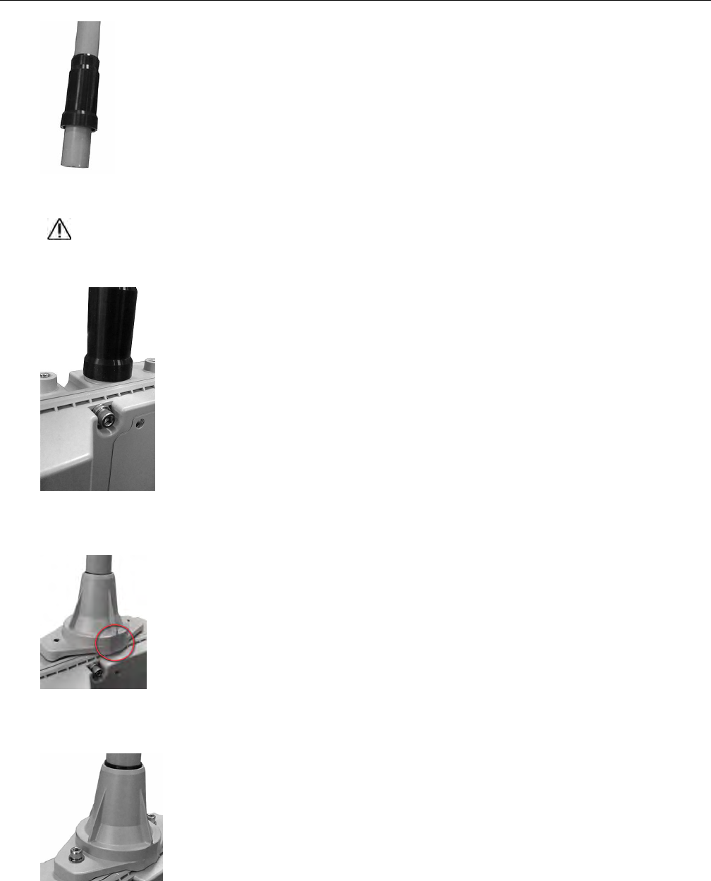
3. Thread the antenna onto the top of the ERT Gateway. Do not over-tighten.
Caution: Do not cross-thread the connection.
4. Push the rubber boot as close as possible to the top of the ERT Gateway.
5. Slide the antenna collar over the antenna with the font of the antenna collar to the front of
the ERT Gateway. The following illustration shows the correct positioning.
6. Secure the antenna collar to the top of the ERT Gateway using screws and washers.
Tighten the screws to 5 to 6 inch-pounds.
Installing the ERT Gateway
ERT Gateway Installation Guide TDC-1744-000 11
Proprietary and Confidential
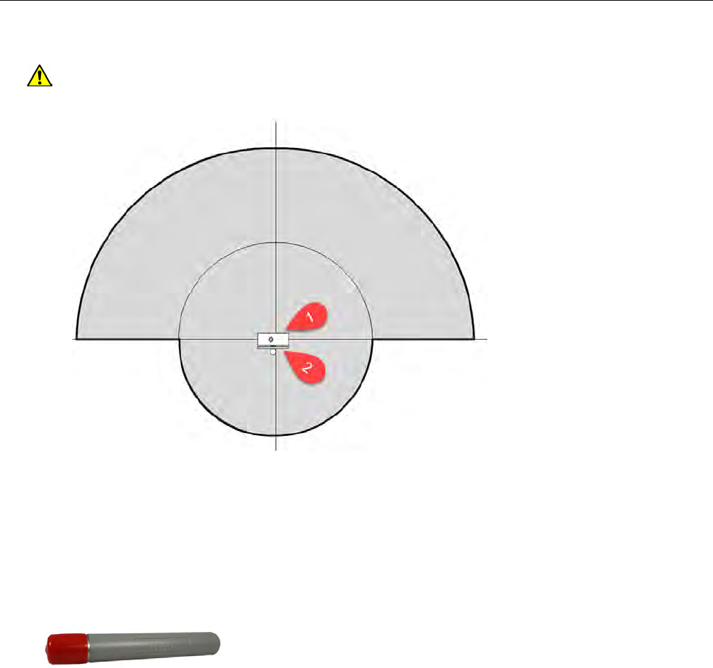
Attaching the backhaul antenna
Warning: Install only the provided backhaul antenna. The backhaul antenna is
directional. Position the ERT Gateway observing the antenna coverage area.
The antenna effective range is approximately 100 feet from the front (1) of the ERT
Gateway and approximately 50 feet to the rear (2) of the device. The shown
coverage area assumes the device is mounted at a height of 25 feet with a clear
line-of-sight path between the ERT Gateway and the programming device.
Positioning the ERT Gateway observing the coverage area guidelines ensures safe
personnel positioning for device programming.
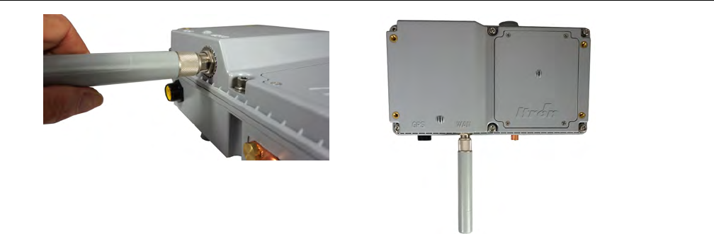
1. Remove the backhaul antenna from the shipping box.
2. Remove the red connector protector.
3. Thread the antenna onto the N-connector (labeled WAN) on the bottom of the ERT
Gateway.
Important: Do not over-tighten or cross-thread the backhaul antenna.
Installing the ERT Gateway
ERT Gateway Installation Guide TDC-1744-000 12
Proprietary and Confidential
Mounting the ERT Gateway
The ERT Gateway can attach to a variety of locations. This chapter provides the instructions
for the listed mounting types.
• Pipe mount
• Pole mount
• Davit arm mount
Mounting hardware
The mounting hardware for the ERT Gateway can be adapted to mount the gateway in
many different locations.
Pole or pipe mount profiles require the listed mounting hardware.
• The mounting plate
• Two mounting brackets
• Four bolts
• The set screw
• (optional) Metal bands (not provided by Itron)
Note: If the vertical pipe or pole exceeds 6.75" in diameter, you may use metal bands
instead of the mounting brackets to secure the mounting plate to the pipe or pole. Two
1.5" long slots are included on the mounting plate to accommodate the metal bands.
The following list describes the required hardware to complete the wall mount profile.
• Two metal mounting brackets
• Four mounting bolts
• Four mounting nuts
• Four lock washers
Installing the ERT Gateway
ERT Gateway Installation Guide TDC-1744-000 13
Proprietary and Confidential
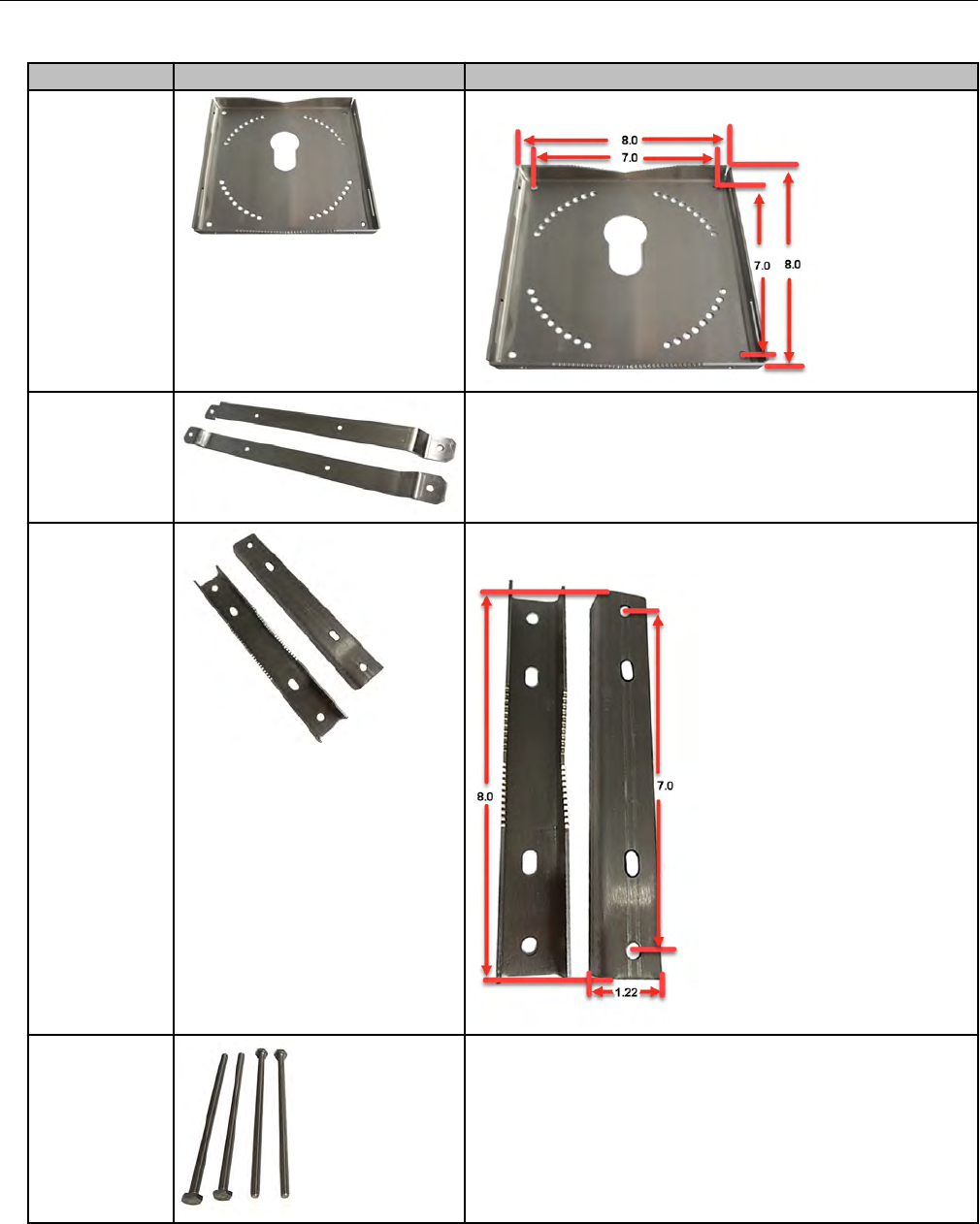
Table : Mounting Hardware
Component Image Description
Mounting plate Mounting plate dimensions
Mounting
brackets
Brackets for wall-mounting
Brackets for pipe or pole mounting (bracket dimensions are
shown)
Mounting bolts Bracket mounting bolts
Installing the ERT Gateway
ERT Gateway Installation Guide TDC-1744-000 14
Proprietary and Confidential
Component Image Description
Miscellaneous Mounting nuts, set screws, washers, split washers, and anti-
seize lubricant
The integrated mounting support on the back of the ERT Gateway housing slides into the
slot in the center of the mounting bracket. A set screw locks the ERT Gateway to the
mounting bracket. The housing orientation can be adjusted ± 16 degrees horizontal to
compensate for different angles.
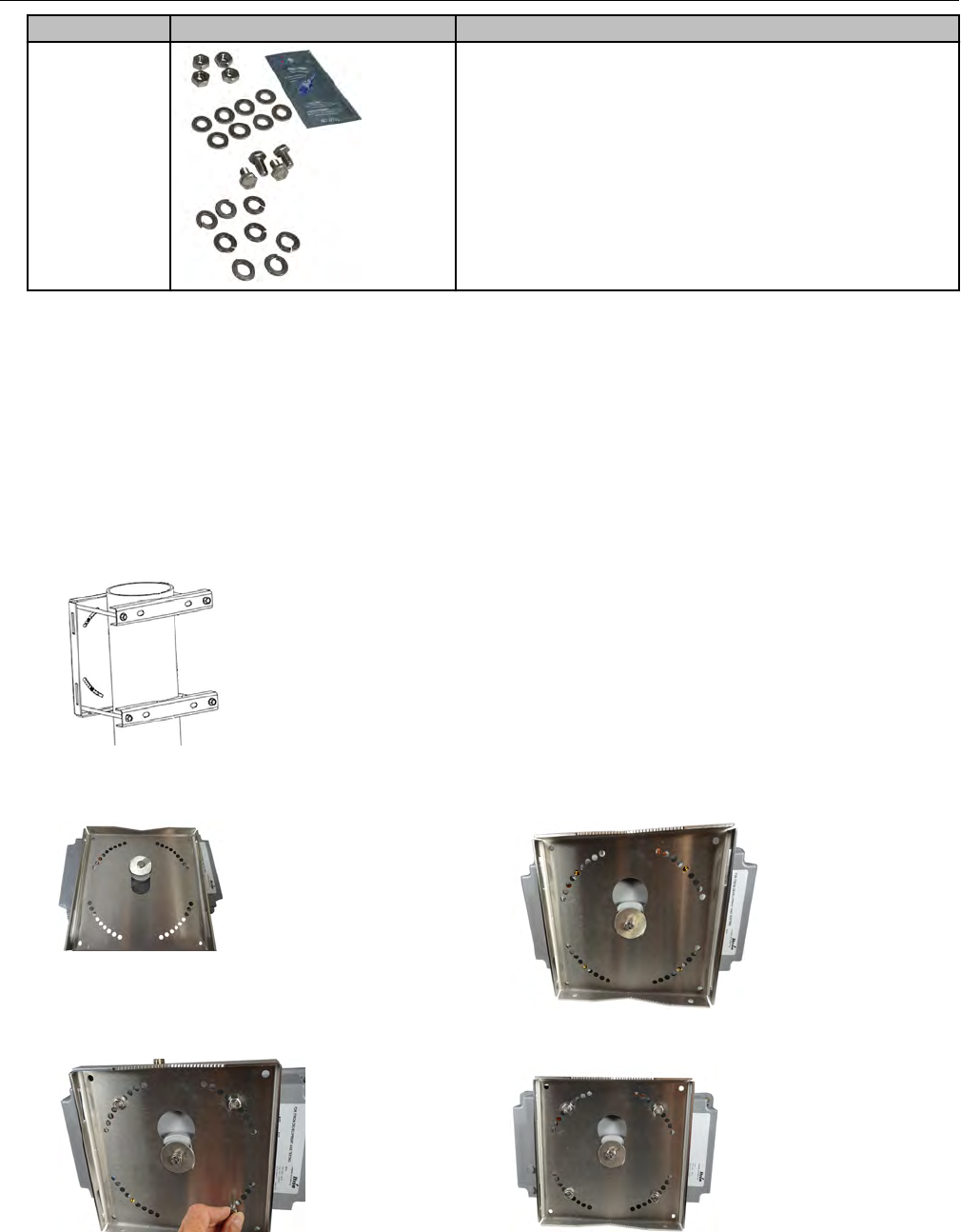
Mounting the ERT Gateway on a pipe
In these instructions, the mounting plate is attached to the vertical pipe with the mounting
brackets. The ERT Gateway housing is secured to the mounting plate.
1. Use the two mounting brackets and four bolts to attach the mounting plate to the pipe.
2. Place the gateway on the mounting plate with the antenna in an upright position. Insert
the mounting plate disc into the mounting plate's disc opening.
3. Secure the ERT Gateway to the mounting plate using the four set screws.
Installing the ERT Gateway
ERT Gateway Installation Guide TDC-1744-000 15
Proprietary and Confidential
Mounting the ERT Gateway on a pole
1. Follow the pipe mounting procedure for securing the mounting plate to the ERT Gateway
(see Mounting the ERT Gateway on a pipe on page 15). Ensure that the ERT Gateway
ERT antenna is in an upright position.
2. Attach the ERT Gateway/mounting bracket assembly to the pole using the mounting
brackets or the optional metal straps.
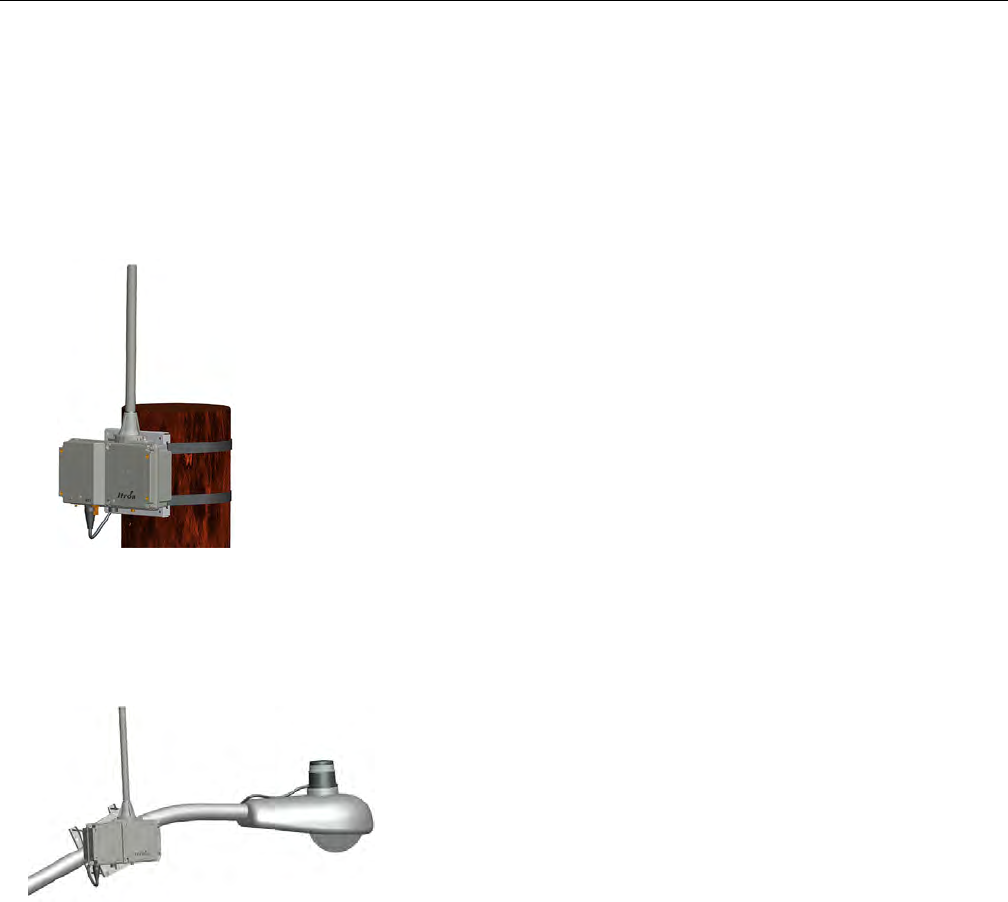
Mounting the ERT Gateway on a davit arm
These instructions describe a typical utility or street light pole installation. The ERT Gateway
is mounted on a davit or street light arm.
Power is supplied on a davit or street light arm installation using a photocell adapter cable.
The cable plugs into the photocell sensor of the street light. If the ERT Gateway is mounted
on a davit arm without a street light, the power cable must be connected according to the
local electrical codes.
Important: If a photocell adapter cable supplies power to the ERT Gateway, the gateway
must be grounded through the grounding lug on the bottom of the housing.
1. Use the two mounting brackets and four bolts to attach the mounting plate to the davit
arm.
Installing the ERT Gateway
ERT Gateway Installation Guide TDC-1744-000 16
Proprietary and Confidential
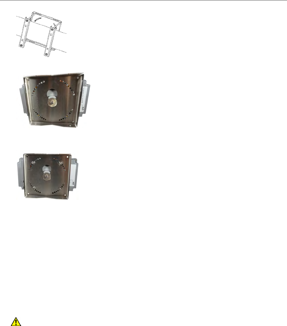
2. Insert the mounting disc into the mounting plate disc opening.
3. Using the set screws, secure the gateway to the mounting plate with the antenna in an
upright position.
Connecting the ground wire
Connect the ground wire to the grounding lug on the ERT Gateway.
Note: Due to variable requirements for cable length, cables are not provided by Itron.
Attach the grounding wire to earth ground. Follow local codes if earth ground is not provided
through the AC power cable.
Connecting the ERT Gateway power
The final step of the ERT Gateway installation is to provide power. A three-pin (AC) cable is
required.
Warning: Securely mount the ERT Gateway before the dedicated AC mains power
source is connected. The ERT Gateway must be grounded by the ground wire in the
three-wire AC mains cable or through the grounding lug on the bottom of the
gateway. For installations connected to the photocell adapter, use the grounding lug
to ground the gateway.
Installing the ERT Gateway
ERT Gateway Installation Guide TDC-1744-000 17
Proprietary and Confidential
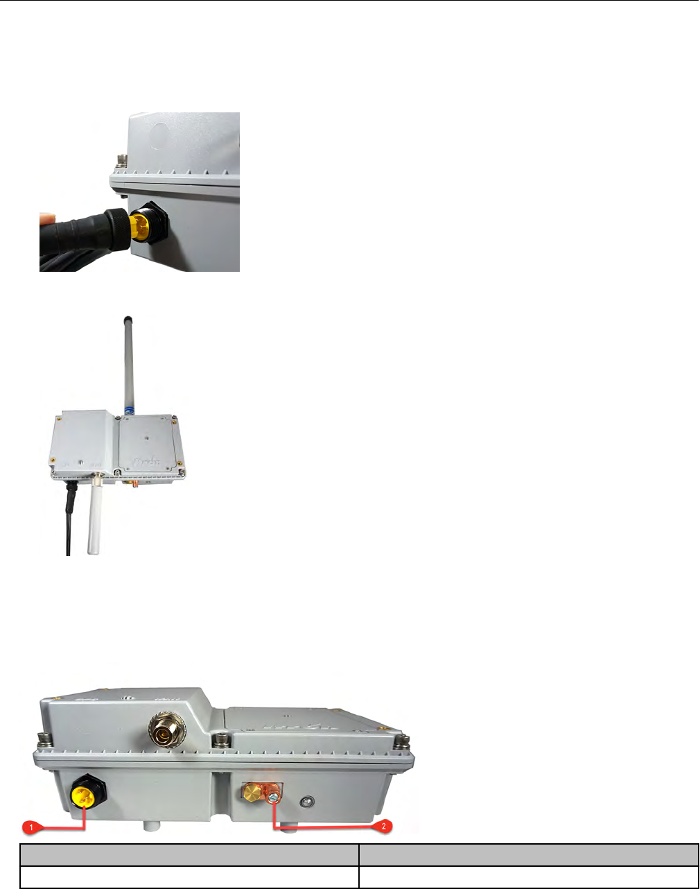
Connecting the power cable
1. Plug the power cable into the power connector on the bottom of the ERT Gateway.
Note: The connector is keyed so the cable connects in the proper orientation.
2. Secure the cable by tightening the retaining nut on the cable.
ERT Gateway wiring diagram
Power source and grounding connection are shown in the following illustration.
Connection Description
1 AC power source
Installing the ERT Gateway
ERT Gateway Installation Guide TDC-1744-000 18
Proprietary and Confidential

Connection Description
2 Ground
Installing the ERT Gateway
ERT Gateway Installation Guide TDC-1744-000 19
Proprietary and Confidential

Chapter 5 OpenWay Riva Routing Node
Communications Software
The OpenWay Riva Routing Node ERT Gateway Star communicates using the OpenWay
Operations Center Collection Manager. The OpenWay Operations Center Collection
Manager sends a request to the ERT Gateway Star requesting the data from the previous 8
hours. The ERT Gateway Star responds with the data that it stored over the past 8 hours.
For more information, see the OpenWay Operations Center Collection Manager
documentation (ERT Gateway related documents on page 3).
ERT Gateway Installation Guide TDC-1744-000 20
Proprietary and Confidential
Appendix A ERT Gateway Specifications
This section provides OpenWay Riva Routing Node ERT Gateway product specifications.
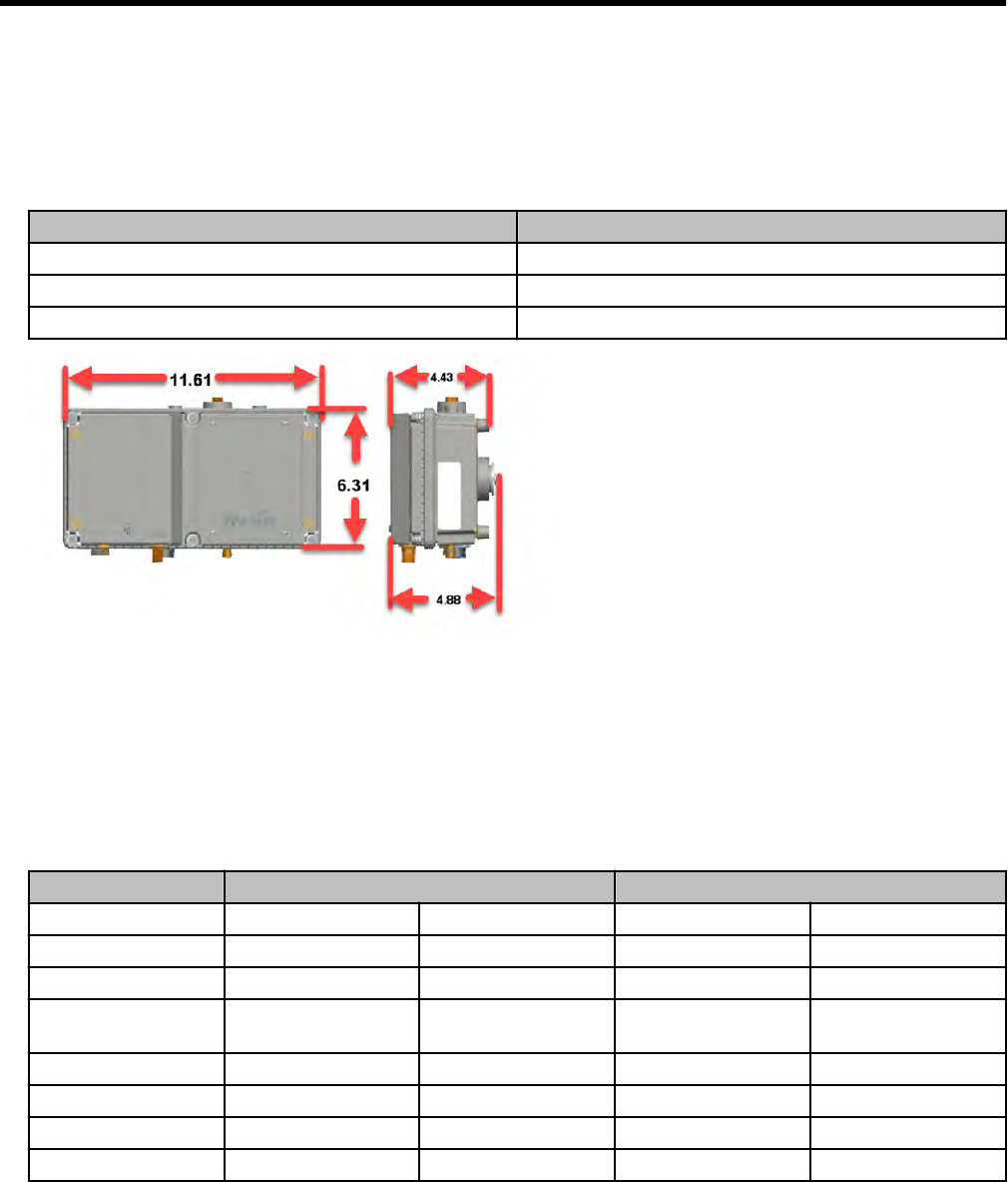
Dimensions and weight
The ERT Gateway weight is listed in pounds. The dimensions are shown in inches.
Component Weight
ERT Gateway 5.5 lbs (with antennas)
Pole mounting kit 3 lbs
Wall mounting kit 2 lbs
Antenna specifications
This section provides the specifications for the 915MHz and backhaul antennas. The ERT
Gateway is designed to operate with the antennas listed here. Antennas not listed here are
strictly prohibited for use with the ERT Gateway. The required antenna impedance is 50
ohms.
Specification 915 MHz ERT antenna 915 MHz backhaul antenna
Itron part number* MSE-0330-001 MSE-0453-001 514618-001 MSE-0452-001
Frequency range 902-932 MHz 902-928 MHz 902-928 MHz 902-928 MHz
Maximum gain 5.15 dBi 5.5 dBi 1 dBi 2.6 dBi
Horizontal
beamwidth
Omnidirectional Omnidirectional Omnidirectional Omnidirectional
Impedance 50 ohms 50 ohms 50 ohms 50 ohms
Termination Type N male Type N Male Type N male Type N male
Overall length 18 in. 18.8" 5.6" 8"
Radome diameter 1" OD 1" OD 0.84" OD 1" OD
*See the OpenWay Riva Routing Node Ordering Guide (PUB-1306-001) for availability or
contact your Itron representative.
ERT Gateway Installation Guide TDC-1744-000 21
Proprietary and Confidential
To reduce potential radio interference to other users, select an antenna type with gain such
that the equivalent isotropically radiated power (e.i.r.p.) is not more than that permitted for
successful communication.
Antenna Conformity
These radio transmitters have been approved to operate (with the antenna types listed
previously) with the maximum permissible gain and required antenna impedance for each
antenna type indicated. Antenna types not included in this list (those having a gain greater
than the maximum gain indicated for that type) are strictly prohibited for use with these
devices.
Environmental specifications
The ERT Gateway meets the listed environmental specifications.
Specification Value
Operating temperature -40°C to 60°C
Storage temperature -40°C to 85°C
Humidity 0 to 90% non-condensing
Transmitter
The ERT Gateway transmitter meets the listed specifications.
Specification Value
Maximum transmit power at ERT antenna
Maximum transmit power at backhaul antenna
Frequency band 902 to 928 MHz (USA/Canada)
ERT Gateway power operating range
The ERT Gateway meets the listed power operating ranges.
Specification Value
Voltage (AC) 102 VAC to 264 VAC
Frequency 47 to 63 Hz
Average power 5 watts
ERT Gateway Specifications
ERT Gateway Installation Guide TDC-1744-000 22
Proprietary and Confidential