Itron PETRC User Manual FCC INFO on Pg 4
Itron, Inc. FCC INFO on Pg 4
UserManual.wiki
>
Itron
>
PETRC User Manual
FCC INFO on Pg 4
Navigation menu
Upload a User Manual
Namespaces
Wiki Guide
HTML
PDF
Info
Views
User Manual
Discussion / Help
Navigation

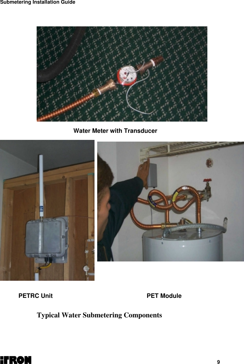
![Submetering Installation Guide8 Required Equipment and Materials for Electronic Installation Hardware • PETRC Unit• Laptop Computer• 40’ Data Cable (Part Number 520-0329-001) [See Figure 1]• 20’ DB9 serial cables• DC/AC Inverter (150 watt minimum)• 50’ AC Electrical Extension Cord• Magnetic roof top antenna• Drill (battery operated)• 12” Drill Bits (regular and able to penetrate walls)• Wrench set up-to 9/16• Socket set up-to 9/16• Screwdrivers (Phillips and Slotted)• Crimp tool• PET Module Software • Microsoft Excel (with Itron scripts and macros)• ProComm Plus• MicroSurvey Data • Installed ERT Population Database including an ERT ID listthat has been checked for corresponding apartmentnumber. (Critical for proper installation)• Maps/diagrams of area• Concentrator configuration/parametersSupplies Lag boltsClean toolsAlcoholNOTE: Use only a dry rag to clean the PETRC unit. No user-serviceable items are in thePETRC unit or PET module unit. If the PETRC unit or PET module is suspected of improperoperation see trouble shooting section of this document,](https://usermanual.wiki/Itron/PETRC/User-Guide-67614-Page-8.png)