FCC INFO on Pg 4

Installation Guide
Submetering System
Palladium Building Project
Seattle, WA
October 7, 1999

Submetering Installation Guide
2
Table of Contents
1.1 Overview
1.2 FCC Regulatory Information
1.3 Purpose
1.4 Scope
1.5 Basic Components
1.5.1 Pet Modules
1.5.2 Network PETRC Units
1.6 Trouble Shooting the System Components

Submetering Installation Guide
3
1.1 Overview
This document is intended to guide the user through the initial set-up of a Water
Gas and Electric Submetering System. The system is made up of usually one or
more PETRC units and up to 600 PET modules.
PETRC units are a receiving device that collects information from the PET
modules via Radio Frequencies in the 902 to 928 MHz band and stores this
information for later retrival by various “head end” software. The device is
powered by 110 Volts AC and incorporates a 3dBd gain antenna.
The PET module is a transmit only device that transmits its consumption
information once each 10 to 15 minutes. The consumption information is
gathered continuously from any pulse output device including Water, Gas and
Electric. The device is for indoor use in a non-condensing environment. The unit
has a battery life of greater than 4 years.
This document is intended to guide the user through the initial set-up of a Water
Gas and Electric Submetering System. The system is made up of usually one or
more PETRC units and up to 600 PET modules.
PETRC units are a receiving device that collects information from the PET
modules via Radio Frequencies in the 902 to 928 MHz band and stores this
information for later retrival by various “head end” software. The device is
powered by 110 Volts AC and incorporates a 3dBd gain antenna.
The PET module is a transmit only device that transmits its consumption
information once each 10 to 15 minutes. The consumption information is
gathered continuously from any pulse output device including Water, Gas and
Electric. The device is for indoor use in a non-condensing environment. The unit
has a battery life of greater than 4 years.Overview

Submetering Installation Guide
4
1.2 FCC Regulatory Information
This equipment has been tested and found to comply with the limits for a Class B
digital device, pursuant to part 15 of the FCC Rules. These limits are designed
to provide reasonable protection against harmful interference in a residential
installation. This equipment generates, uses and can radiate radio frequency
energy and, if not installed and used in accordance with the instructions, may
cause harmful interference to radio communications. However, there is no
guarantee that interference will not occur in a particular installation. If this
equipment does cause harmful interference to radio or television reception, which
can be determined by turning the equipment off and on, the user is encouraged
to try to correct the interference by one or more of the following measures:
• Reorient or relocate the receiving antenna.
• Increase the separation between the equipment and receiver.
• Connect the equipment into an outlet on a circuit different from that to which
the receiver is connected.
• Consult the dealer or an experienced radio/TV technician for help.
This device complies with part 15 of the FCC Rules. Operation is subject to the
following two conditions:
1. This device may not cause harmful interference, and
2. This device must accept any interference received, including interference
that may cause undesired operation.
Service Requirements
The PET modules and PETRC units have no user serviceable parts.
In the event of equipment malfunction, all repairs should be performed by Itron. It
is the responsibility of users requiring service to report the need for service to our
company. For service call 1-800-635-5461 and ask for the Customer Service
Department.
Caution changes or modifications not expressly approved by Itron, Inc. could void
the user’s authority to operate this equipment.

Submetering Installation Guide
5
1.3 Purpose
This document is intended to aid installation personnel involved in the installation
and operation of the SubMetering network’s PETRC unit and PET module and
become familiar with the details of the design. This document describes how the
units operates as a system and does not detail the specified limits or the
performance.
1.4 Scope
This document covers the Revision 1 of system hardware. Functional blocks are
broken down into component or group of components and explanations of how
they operate with each other, their inputs and outputs are given.
1.5 Basic Components of Itron’s Submetering Network
1.5.1 PET Modules
Itron’s Meter End Point RF Devices or PET modules encode consumption and
tamper information, then transmit this data and other information via RF to the
network PETRC units. The PET modules for Electric meters are normally
installed under the glass of standard meters and do not require battery power;
the Devices for Gas and Water meters are self-contained low-power units,
powered by long-life batteries. PET modules can be installed by the meter
manufacturer during the manufacturing process or easily retrofitted into most
existing meters.
1.5.2 Network PETRC Units
The network PETRC unit receives Water, Electric and Gas usage data via RF
from the PET modules, and transmits the data to the head-end MV-RS meter
reading software via telephone or cellular telephone. Two types of PETRC units
are utilized in the network: the base PETRC unit and relay PETRC units. The
base PETRC unit is similar to all other PETRC units except it is equipped with a
telephone connection. The telephone connection can be either a standard line or
a cellular type.
An optional cellular phone interconnect can be utilized on either a temporary or
permanent basis depending on the application. As a temporary option, the
varying lead time of telephone installation can be circumvented by utilizing the
cellular phone interconnect option until a cost-effective solution can be installed.
In large scale roll-outs, often in areas large enough to span multiple telephone
companies’ service territories, a single contact within one telephone company is
often not available, which inevitably results in delays. With the cellular telephone
option, these delays can be eliminated. Additionally, the cellular telephone
option can be migrated from new installation to new installation as hard-wired
telephone services are eventually installed at each site.
The base PETRC unit is generally mounted at a central point in a apartment
complex where ease of interconnection to power and telephone lines are
available. This base unit can monitor and retain data on up to 600 Water,

Submetering Installation Guide
6
Electric, and Gas PET modules. All Water, Electric, and Gas usage data is
gathered from the PET modules via a Frequency Hopping Spread Spectrum RF
technology. Having the PET modules utilize a very slow “bubble up” rate
minimizes the power consumption of the PET module, thus providing a much
longer field life. The slow bubble up rate also minimizes unnecessary RF
interference to other users in the RF band.
The relay PETRC unit provides a store-and-forward functionality in the network.
This unit receives PET module RF transmissions from surrounding PET modules,
adds a time stamp, and upon a predetermined time, forwards the stored PET
module data to other PETRC units (either additional relay PETRC units or the
base PETRC unit). Up to 8 levels can be configured in a string of PETRC units.
Each level can communicate with all of the units at lower levels. Thus, the
system can be configured to provide universal coverage in typical multi-dwelling
or high rise environments.
The ruggedized PETRC unit (both base and relay) is capable of being mounted
outside and is impervious to weather and potential vandalism.
Water, Electric and Gas usage data transmitted by the network PETRC unit via
telephone or cellular telephone is processed by the head-end MV-RS Meter
Reading Software. The MV-RS system runs on a standard PC. MV-RS not only
processes data received from network PETRC units, it provides an interactive,
graphical user interface to allow users to extract and report key information.
Itron’s MV-RS Meter Reading Software has been deployed throughout the world
at over hundreds of locations. Originating within the utility market, this Multi-
Vendor Reading Software has years of reliable service with millions of meters
read. Itron has chosen the MV-RS Meter Reading Software, along with the
network PETRC units and the PET modules, as key components in Itron’s
Submetering Network because of their substantial history of reliable operations in
the utility meter reading environment around the world.

Submetering Installation Guide
7
Figure 1 - Basic Components of Itron’s Submetering Network
PET Modules – Itron’s Meter End Point RF devices or PET modules are installed into the Water,
Electric and Gas meters and transmit usage data via RF to the PETRC unit
.
Network PETRC Unit – Itron’s Network PETRC unit receives Water, Electric and Gas usage
data via RF from the PET module, and sends the data to the head-end MV-RS Meter Reading
Software via telephone or cellular telephone.
MV-RS Meter Reading Software - Water, Electric and Gas usage data sent by the network
PETRC unit via telephone or cellular telephone is processed by the head-end MV-RS Meter
Reading Software.
Cellular Site
Base
Concentrator
Modem
PSTN
MV-RS
Meter Reading
Software
Relay
Concentrators
Gas
Meter End Point
RF Device
Electric
Meter End Point
RF Device
Water
Meter End Point
RF Device
Ovals
Represent
Antenna
Patterns of
Concentrators

Submetering Installation Guide
8
Required Equipment and Materials for Electronic Installation
Hardware • PETRC Unit
• Laptop Computer
• 40’ Data Cable (Part Number 520-0329-001) [See Figure 1]
• 20’ DB9 serial cables
• DC/AC Inverter (150 watt minimum)
• 50’ AC Electrical Extension Cord
• Magnetic roof top antenna
• Drill (battery operated)
• 12” Drill Bits (regular and able to penetrate walls)
• Wrench set up-to 9/16
• Socket set up-to 9/16
• Screwdrivers (Phillips and Slotted)
• Crimp tool
• PET Module
Software • Microsoft Excel (with Itron scripts and macros)
• ProComm Plus
• MicroSurvey
Data • Installed ERT Population Database including an ERT ID list
that has been checked for corresponding apartment
number. (Critical for proper installation)
• Maps/diagrams of area
• Concentrator configuration/parameters
Supplies Lag bolts
Clean tools
Alcohol
NOTE: Use only a dry rag to clean the PETRC unit. No user-serviceable items are in the
PETRC unit or PET module unit. If the PETRC unit or PET module is suspected of improper
operation see trouble shooting section of this document,
Submetering Installation Guide
9
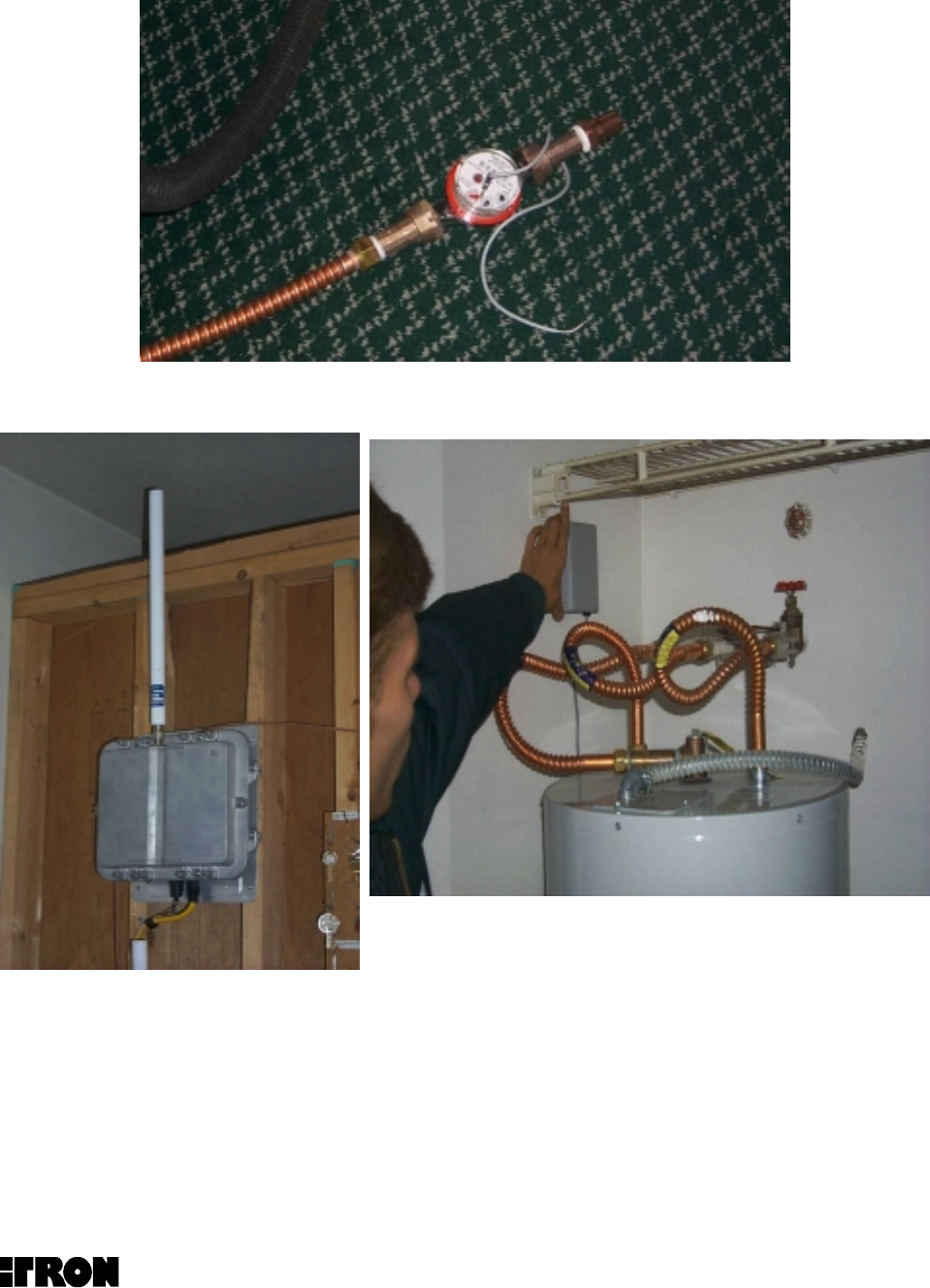
Water Meter with Transducer
PETRC Unit PET Module
Typical Water Submetering Components
Submetering Installation Guide
10
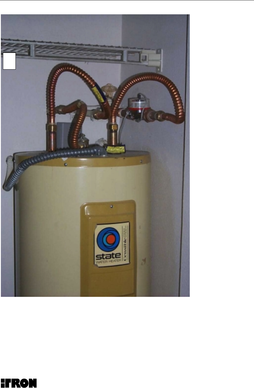
Wrong Way to Install a Pet Module
Note that the PET Module is installed behind hot water tank and under the
copper tubing. The preferred location in this instant would be at least 6 inches
from any metal surfaces as indicated

Submetering Installation Guide
11
1.6 Trouble Shooting the MicroNetwork Components
If you have difficulties with overall system operation this generally indicates a
PETRC unit problem. If you are having problems with some of the PET units this
may be an PETRC antenna or interference problem The following information
details some basic items that a user can do to correct most difficulties.
The PETRC Unit and the PET module has "No internal user Serviceable
Components" and must be returned to Itron in Spokane, WA for service. Call
1800 635 5461 and ask for Customer Service
Before you begin:
• The PC and the PETRC unit must both be powered on. Use the Itron-
supplied Concentrator power cable to power the Concentrator unit.
• With the PC and the Concentrator powered ON, connect the
Concentrator unit to the PC using the Itron-provided diagnostic
cable. The 10 pin end of the cable should be connected to the
diagnostic port on the Concentrator unit and the 9 pin end of cable
should be connected to the Com 1 com port of the PC.
Step 1:
• Click the Window 95 “Start” button in the lower left portion of the PC screen.
• Choose the “Programs” menu option.
• Choose the “MicroSurvey” menu option.
• Choose the “MicroSurvey” menu option.
• Choose “OK” on the “Select Port” screen that appears (leave the “Com 1”
default selection).
NOTE:
• The MicroSurvey application screen should appear. Maximize screen
using the maximize button in the upper right of the screen.
• The “Connection:” field on the MicroSurvey screen should be set to the
“Direct Connection” default.
Step 2:
• Click the “Terminal” button on the MicroSurvey application screen.
• In the “Terminal Screen” that appears,

Submetering Installation Guide
12
• Click the “Debug ON” button.
NOTE:
• The “Terminal Screen” screen will begin to scroll information.
NOTE:
If Information does not scroll on the screen the unit is not operating
properly and must be returned to ITRON
• Allow the system to operate independently for approximately 10 minutes.
• Click the “Receive” button.
• Click the “Debug OFF” button.
• Click the “Close” button.
Step 3:
• Click the “ERT Database” tab on the MicroSurvey application screen.
• Click the “Dial” button.
NOTE:
• The “Status Window” screen will scroll information and a “Download”
screen will be displayed.
• The first time that the “Dial” button is clicked, an error condition may occur.
To proceed, wait 10 seconds and click the “Dial” button again.
• When the “Download” screen disappears, the fields in the “ERT Database”
tab table will be filled.
Importing Site Data into the MicroSurvey Application:
Step 1:
• Click the “Import” button on the MicroSurvey screen.
• In the browser screen that appears, choose “All Files” in the “Files of Type:”
field.
• Locate your comma separated (CSV format using Microsoft Excel) file
containing two fields (ERT ID and ERT Location) and double click on the file
name.
• Verify that your comma separated file has been imported into the
MicroSurvey application by clicking the “ERT Database” tab on the
MicroSurvey application screen.
NOTE:
• The “ERT ID” and the “Location” fields should contain your data.
Exporting Field Survey Data from the MicroSurvey Application:

Submetering Installation Guide
13
Step 1:
• Click the “Export” button on the MicroSurvey application screen.
• In the “Export Text File Name” screen that appears, choose the exported data
destination in the “Save in:” field.
• Name the exported data file in the “File name” field (do not add an extension
to the file name).
• Use the default “Text File (*.txt)” in the “Save as type:” field.
• Click the “Save” button.
Step 2:
• Click the “Delete All” button on the MicroSurvey application screen.
NOTE:
• This clears the MicroSurvey database in preparation for the next field
survey.
Step 3:
• Launch Microsoft Excel from the Windows “Start” button.
• Under the “File” menu, choose “Open”
• In the “Open” screen that appears, choose “All Files (*.*) in the “Files of type:”
field.
• Locate the exported data file. (It should have a .txt extension.)
• Double click on the exported data file.
• In the “Text Import Wizard-Step 1 of 3” screen that appears, choose the
“Delimited” button in the “Original data type” field.
• Click the “Next” button.
• In the “Text Import Wizard-Step 2 of 3” screen that appears, choose the
“Comma” button in the “Delimiters” field.
• Click the “Next” button.
• In the “Text Import Wizard-Step 3 of 3” screen that appears, choose the
“Finish” button.
NOTE:
• An Excel spreadsheet will appear with the exported data in it.
• Select the entire spreadsheet by holding down the “Ctrl” key and clicking the
“a” key.
• Under the “Data” menu choose “Sort”.
• In the “Sort” screen that appears
• Select the “Header row” button in the “My list has” field.
• Select “Location” in the pull down list in the “Sort by” field.

Submetering Installation Guide
14
• Also select the “Ascending” button in the “Sort by” field.
Analyzing Survey Data:
• The Field Survey data is now sorted by location. The presence of ERT data
in columns B through G in the Excel spreadsheet indicates that the PET
Module was received by the PETRC unit.