Itron PETRPTR Water submetering system repeater User Manual PETNET InstallGuide SLC032301TCB
Itron, Inc. Water submetering system repeater PETNET InstallGuide SLC032301TCB
UserManual.wiki
>
Itron
>
PETRPTR User Manual
Manual
Navigation menu
Upload a User Manual
Namespaces
Wiki Guide
HTML
PDF
Info
Views
User Manual
Discussion / Help
Navigation
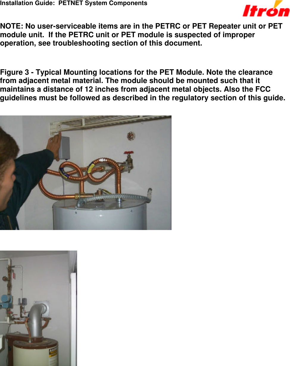
![Installation Guide: PETNET System Components 6.0 Required Equipment and Materials for Electronic Installation Hardware • PETRC Unit • PET Repeater unit and required antenna and coaxial cable • Laptop Computer • 40’ Data Cable (Part Number 520-0329-001) [See Figure 1] • 20’ DB9 serial cables • DC/AC Inverter (150 watt minimum) • 50’ AC Electrical Extension Cord • Magnetic roof top antenna • Drill (battery operated) • 12” Drill Bits (regular and able to penetrate walls) • Wrench set up-to 9/16 • Socket set up-to 9/16 • Screwdrivers (Phillips and Slotted) • Crimp tool • PET Module Software • Microsoft Excel • ProComm Plus • MicroSurvey Data • Installed PET Population Database including an PET ID list that has been checked for corresponding apartment number. (Critical for proper installation) • Maps/diagrams of area • PETRC configuration/parameters Supplies Lag bolts Antenna Brackets Grounding rod 60 feet of #10 solid core cable Cable clamps Clean tools Alcohol](https://usermanual.wiki/Itron/PETRPTR/User-Guide-142094-Page-9.png)