Itron PETRPTR Water submetering system repeater User Manual PETNET InstallGuide SLC032301TCB
Itron, Inc. Water submetering system repeater PETNET InstallGuide SLC032301TCB
Itron >
Manual

Installation Guide for the PETRC and
PET Repeater Units used in the
PETNET Submetering System
Installation of this equipment can only be accomplished by experienced, trained
professionals.
The guide details a number of Safety Requirements which must be followed in
order to protect the general public.
Submitted February 20, 2001
In accordance with FCC Regulations
Itron Inc. 2001

Installation Guide: PETNET System Components
TABLE OF CONTENTS
1.0 OVERVIEW................................................................................................................3
2.0 FCC REGULATORY INFORMATION..............................................................................4
3.0 SERVICE REQUIREMENTS...........................................................................................5
4.0 REGULATORY APPROVALS ........................................................................................5
5.0 SCOPE .....................................................................................................................5
7.0 INSTALLATION AND DIAGNOSTIC SETUP....................................................................12
8.0 CONSOLE COMMANDS.............................................................................................12
9.0 TROUBLESHOOTING THE PETNET SUBMETERING COMPONENTS ...............................15

Installation Guide: PETNET System Components
1.0 Overview
This document is intended to guide the user through the initial set-up of a Water Submetering
System. The system is made up of usually one or more PETRC units and up to 1000 PET
modules.
PETRC units are a receiving device that collects information from the PET modules via Radio
Frequencies in the 902 to 928 MHz band and stores this information for later retrieval by various
“head end” software. The device is powered by 110 Volts AC and incorporates a 3dBd gain
antenna.
PET Repeater unit operates similar to the PETRC in that collects information from the PET
modules however , the collected information is forwarded to the PETRC unit via RF. This unit is
equipped with a 5 DbD gain antenna and associated coaxial cable. This antenna and cable
assembly must be used without modification.
The PET module is a transmit only device that transmits its consumption information once each
10 to 15 minutes. The consumption information is gathered continuously from any pulse output
device including Water. The device is for indoor use in a non-condensing environment. The unit
has a battery life of greater than 4 years.
This document is intended to guide professional and trained installer through the initial set-up of
a Water Submetering System. The system is made up of usually one or more PETRC units, PET
Repeaters and up to 1,000 PET modules.

Installation Guide: PETNET System Components
2.0 FCC Regulatory Information
This equipment has been tested and found to comply with the limits for a Class B digital device, pursuant
to part 15 of the FCC Rules. These limits are designed to provide reasonable protection against harmful
interference in a residential installation. This equipment generates, uses and can radiate radio frequency
energy and, if not installed and used in accordance with the instructions, may cause harmful interference
to radio communications. However, there is no guarantee that interference will not occur in a particular
installation. If this equipment does cause harmful interference to radio or television reception, which can
be determined by turning the equipment off and on, the user is encouraged to try to correct the
interference by one or more of the following measures:
• Reorient or relocate the receiving antenna.
• Increase the separation between the equipment and receiver.
• Connect the equipment into an outlet on a circuit different from that to which the receiver is
connected.
• Consult the dealer or an experienced radio/TV technician for help.
This device complies with part 15 of the FCC Rules. Operation is subject to the following two
conditions:
1. This device may not cause harmful interference, and
2. This device must accept any interference received, including interference that may cause
undesired operation.
Important Installation Notes: This device complies with Part 15.247 of the FCC rules
governing spread spectrum devices. The Pet module operates in the 900 MHz unlicensed
band at a maximum peak power level of 40 milliwatts with a transmission rate not to
exceed one transmission every 10 minutes and a transmission time not to exceed 50
milliseconds. This device must be permanently mounted such that it retains a distance of
20 centimeters (7.9 inches) from all persons in order to comply with FCC RF exposure
levels. The device cannot be modified in any way and contains no user serviceable
parts.
The PET Repeater unit complies with Part 15.247 of the FCC rules governing spread
spectrum devices. The Echo unit operates in the 900 MHz unlicensed band at a maximum
peak power level of 200 milliwatts with a transmission rate not to exceed one
transmission every 20 seconds and a transmission time not to exceed 400 milliseconds.
This device may be mounted in any location however the antenna must be permanently
mounted such that it retains a distance of 2 meters (6.7 feet) from all persons in order to
comply with FCC RF exposure levels. In order guarantee FCC complaints and the
performance of the PETNET system, the antenna, coaxial cable must be used exactly as
provided from Itron. The device antenna and coaxial cable cannot be modified in any way
and contains no user serviceable parts.
Caution to users: This device, antenna and coaxial assembly shall not be changed or
modified without the expressed approval of Itron. Any modification could void the user’s
authority to operate the equipment.

Installation Guide: PETNET System Components
3.0 Service Requirements
The PET modules, PET Repeater and PETRC units have no user serviceable parts. In the event
of equipment malfunction, all repairs should be performed by Itron. It is the responsibility of
users requiring service to report the need for service to our company. For service call 1-800-
635-5461 and ask for the Customer Service Department.
4.0 Regulatory Approvals
As detailed later in this document, Itron believes the PETRC and PET Repeater units require the
following approvals:
• FCC Part 15: Class B digital device, per Rule 15.9(a), 15.107(a)
• FCC Part 15: Receiver at 902-928 MHz, per Rule 15.109
• FCC Part 15: Frequency Hopping Spread Spectrum Intentional Radiator, per Rule 15.247
• CSA: Listing for compliance with US National Electric Code
5.0 Scope
This document is intended to aid installation personnel involved in the installation and operation
of the SubMetering network’s PETRC, PET Repeater unit and PET module and become
familiar with the details of the design. This document describes how the units operates as a
system and does not detail the specified limits or the performance.
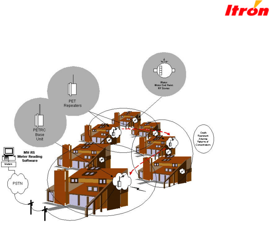
5.1 Basic Components of Itron’s Submetering Network
Itron, Inc. (“Itron”) is the manufacturer of remote utility meter reading products. Itron’s meter
end point RF devices or PET modules encode consumption and tamper information, then
transmit this data and other information via RF to the network PETRC units and/or the PET
Repeater units.
5.1.1 PET Module
The PET modules for water meters are self-contained low-power units, powered by long-life
batteries. PET modules can be installed by the meter manufacturer during the manufacturing
process or easily retrofitted into most existing meters.
5.1.2 Network PETRC and PET Repeater Units
The network PETRC unit receives water usage data via RF from the PET modules, and transmits
the data to the head-end MV-RS meter reading software via telephone or cellular telephone.
Two types of units are utilized in the network: the PETRC unit and PET Repeater units. The
base PETRC unit is similar to the PET Repeater unit except that it is equipped with a telephone
connection. The telephone connection can be either a standard line or a cellular type.
An optional cellular phone interconnect can be utilized on either a temporary or permanent basis
depending on the application. As a temporary option, the varying lead time of telephone
installation can be circumvented by utilizing the cellular phone interconnect option until a cost-

Installation Guide: PETNET System Components
effective solution can be installed. In large scale roll-outs, often in areas large enough to span
multiple telephone companies’ service territories, a single contact within one telephone company
is often not available, which inevitably results in delays. With the cellular telephone option,
these delays can be eliminated. Additionally, the cellular telephone option can be migrated from
new installation to new installation as hard-wired telephone services are eventually installed at
each site.
The base PETRC unit is mounted at a central point in an apartment complex where ease of
interconnection to power and telephone lines are available. This base unit can monitor and retain
data on up to 1000 Water PET modules. Water usage data is gathered from the PET modules via
a Frequency Hopping Spread Spectrum RF technology. Having the PET modules utilize a very
slow “bubble up” rate minimizes the power consumption of the PET module, thus providing a
much longer field life. The slow bubble up rate also minimizes unnecessary RF interference to
other users in the RF band.
The PET Repeater unit provides a store-and-forward functionality in the network. This unit
receives PET module RF transmissions from surrounding PET modules, adds a time stamp, and
upon a predetermined time, forwards the stored PET module data to other PETRC units (either
through additional PET Repeater units or the base PETRC unit). Up to 7 levels can be configured
in a string of PET Repeater units. Each level can communicate with all of the units at lower
levels. Thus, the system can be configured to provide universal coverage in typical multi-
dwelling or highrise environments.
The ruggedized PETRC and PET Repeater units are capable of being mounted outside and is
impervious to weather and potential vandalism.
Water usage data transmitted by the network PETRC unit via telephone or cellular telephone is
processed by the head-end MV-RS Meter Reading Software. The MV-RS system runs on a
standard PC. MV-RS not only processes data received from network PETRC units, it provides
an interactive, graphical user interface to allow users to extract and report key information.
Itron’s MV-RS Meter Reading Software has been deployed throughout the world at over
hundreds of locations. Originating within the utility market, this Multi-Vendor Reading
Software has years of reliable service with millions of meters read. Itron has chosen the MV-RS
Meter Reading Software, along with the network PETRC units and the PET modules, as key
components in Itron’s PETNET Submetering Network because of their substantial history of
reliable operations in the utility meter reading environment around the world.
Installation Guide: PETNET System Components
Figure 1 - Basic Components of Itron’s PETNET Submetering Network
Installation Guide: PETNET System Components
Figure 2 - Basic System Design of Itron’s PETNET Submetering Network Figure
PET Modules – Itron’s Meter End Point RF devices or PET modules are installed into the
Water, Electric and Gas meters and transmit usage data via RF to the PETRC unit
Network PETRC Unit – Itron’s Network PETRC unit receives Water, Electric and Gas usage
data via RF from the PET module, and sends the data to the head-end MV-RS Meter Reading
Software via telephone or cellular telephone.
PET Repeater Unit – Itron’s Network PET Repeater unit receives water, usage data via RF
from the PET module, and sends the data to the PETRC unit. The PET Repeater unit operates
similar to the PET in that it utilizes Frequency Hopping Spread Spectrum on a timed basis. The
transmission are relatively short < 400ms and communicate up to 45 PET message per
transmission. The PETRC unit synchronizes its receiver to the PET Repeater’s transmission
following acquisition. The PET Repeater unit also provides an identification number with each
transmission. The identification numbers of all PET Repeaters in the PETNET system are
entered into the PETRC unit to allow reception into the system database.
MV-RS Meter Reading Software - Water, Electric and Gas usage data sent by the network
PETRC unit via telephone or cellular telephone is processed by the head-end MV-RS Meter
Reading Software.

Installation Guide: PETNET System Components
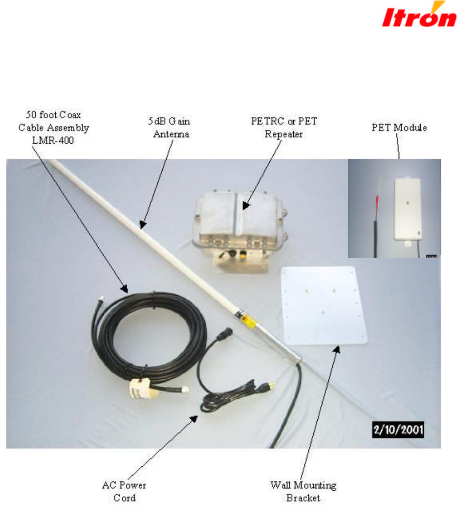
6.0 Required Equipment and Materials for Electronic Installation
Hardware • PETRC Unit
• PET Repeater unit and required antenna and
coaxial cable
• Laptop Computer
• 40’ Data Cable (Part Number 520-0329-001)
[See Figure 1]
• 20’ DB9 serial cables
• DC/AC Inverter (150 watt minimum)
• 50’ AC Electrical Extension Cord
• Magnetic roof top antenna
• Drill (battery operated)
• 12” Drill Bits (regular and able to penetrate
walls)
• Wrench set up-to 9/16
• Socket set up-to 9/16
• Screwdrivers (Phillips and Slotted)
• Crimp tool
• PET Module
Software • Microsoft Excel
• ProComm Plus
• MicroSurvey
Data • Installed PET Population Database including an
PET ID list that has been checked for
corresponding apartment number. (Critical for
proper installation)
• Maps/diagrams of area
• PETRC configuration/parameters
Supplies Lag bolts
Antenna Brackets
Grounding rod
60 feet of #10 solid core cable
Cable clamps
Clean tools
Alcohol
Installation Guide: PETNET System Components
NOTE: No user-serviceable items are in the PETRC or PET Repeater unit or PET
module unit. If the PETRC unit or PET module is suspected of improper
operation, see troubleshooting section of this document.
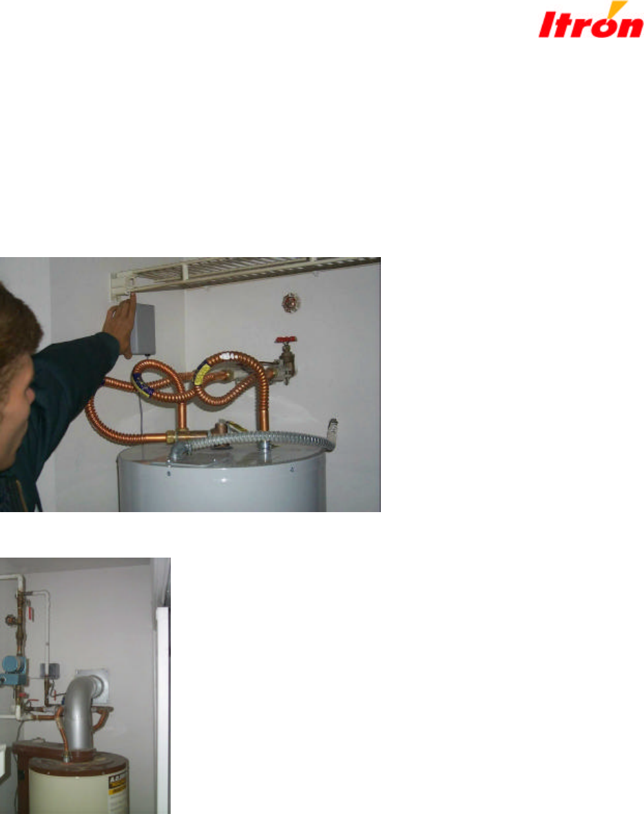
Figure 3 - Typical Mounting locations for the PET Module. Note the clearance
from adjacent metal material. The module should be mounted such that it
maintains a distance of 12 inches from adjacent metal objects. Also the FCC
guidelines must be followed as described in the regulatory section of this guide.
Installation Guide: PETNET System Components
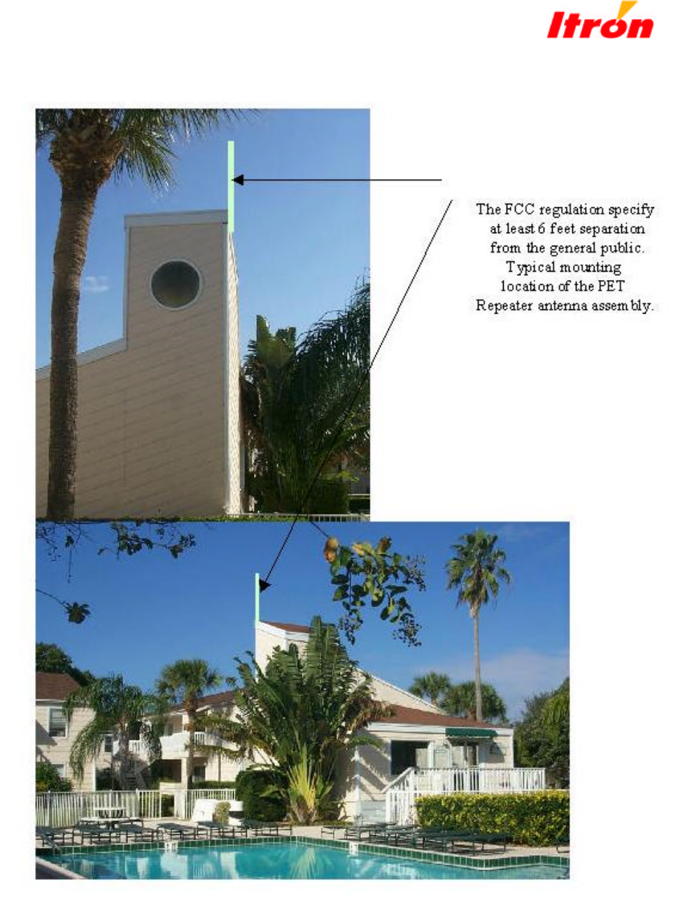
Figure 4 – Typical Mounting Location for the PET Repeater antenna

Installation Guide: PETNET System Components
The PET Repeater antenna is typically mounted in an elevated unobstructed location in order to
provide the maximum coverage between the PET modules as well as other repeaters and PETRC
units. The antenna must be grounded utilizing a # 10 gauge solid core wire and suitable ground.
In some cases a 6 foot grounding rod must be installed and connected to the #10 ground cable.
This connection must be install such that it is weather resistant. Proper material is available at
most electrical supply outlets.
7.0 Installation and Diagnostic Setup
Once the PET modules and PETRC is installed, configuration and coverage testing can begin.
The following paragraph desribe the set up procedure and configuration options.
The data cable is connected to a PC running a copy of Procomm. This software
communications package provides a number of features for displaying and capturing data for
review. Identify which COM port is available on the PC and attach the Itron Inc. data cable.
Tell Procomm which port is being used by assigning a direct connection to it and setting the
communications parameters to 19200/N/8/1.
Enter (lower case) ‘c’<enter> on the computer keyboard and observe the test computer’s display.
An ‘R>’ should appear. Repeat the previous step if the ‘R>’ did not appear. Note: Occasionally
the PETRC will ignore the communications port while it completes higher level tasks internally
that are related to collecting and managing incoming PET data. It may be necessary to repeat
the (lower case)’c’<enter> several times.
Once the R> has appeared on the screen enter the following command:
debug=y
cexit<enter>
Note: All of the console commands, with the exception of a few diagnostic commands are
entered as lower case characters – be sure the CAPS Lock is ‘OFF’.
At this time the display should be filling with information related to the tracking and processing
of PET data. The PETRC uses several different colors for different kinds of information
displayed. The reverse video lines of information relate to the ‘Large Block’ forwarding process.
If the equipment does not respond to keyboard requests check the following:
CAPS Lock (must be ‘OFF’, entries are in lower case)
Data cable from PETRC to test computer
Computer COM ports and COM port setup in Procomm
8.0 Console Commands
This section describes the commands available from the console mode. These commands are
readily available to the operator that has connected a remote computer, normally running

Installation Guide: PETNET System Components
ProComm software, to the PETRC’s serial port. The method of connection can be either via
modem or directly coupled with the appropriate data cable supplied by Itron Inc..
Note: All console commands are entered in lower case, be sure CAPS LOCK is
off.
The following commands are listed in alphabetically order:
blist Lists all of the active PETs in the PETRC database at once. The data is intended to be
captured by a remote computer program like the data capture feature in Procomm.
cexit The correct way to exit ‘console’ mode is to enter cexit. This allows information to be
saved in memory properly and begin the unattended application mode.
clear This clears the PET database without clearing the arrivals list. This allows the operator to
quickly collect new PET readings since the PETRC does not have to reacquire the PET
timing and channel again.
clearp This command clears the PET database and the arrivals list. All PET information must
now be re-acquired again.
chclr Chclr will clear the channel count data. To view the data before clearing enter ‘cview’.
clbat Clbat clears the low battery flag on all of the PETs stored in the PETRC database.
clist Clist counts all of the active PETs in the database and reports the number.
commd Commd allows the operator to turn off port diagnostic information that appears on
the screen.
commd=1, eliminates extra characters
commd=0, allows extra characters
cview Cview displays the number of successful packets received on each of the 25 receiver
channels.
dbtim Dbtim sets the amount of time that the PET will reside in the database without being
refreshed.
debug Debug is a mode of operation that will send additional messages to the screen while the
system is tracking and acquiring data. This mode is used for test.
delay Delay allows the operator to increase the delay time before a packet is retransmitted.
displ Displ limits the amount of debug data that is presented on the display.
displ=1 for terse messages
displ=0 for verbose or traditional messages

Installation Guide: PETNET System Components
dlist Dlist will list the PETs that are active in the database along with associated packet
information.
elist Elist will list the PETs that are active in the database – 3 column format, screen at a time.
gohop Gohop allows the operator to override the random number generator for the first large
block transmission frequency. The local transmitting Class 1 PETRC will initiate its
hopping sequence with the gohop value entered. The hopping sequence is tied to the
serial number, however, the starting hop is redirected.
gohop=24 for causing the first transmission to utilize frequency 926.1Mhz
lbint Lbint sets the repeat interval for sending pre-emptive large block transmissions.
lwbat Lwbat will reset all of the PETs low battery flag that reside in the PETRC’s database.
pchnl Pchnl sets the acquisition channel that the receiver will utilize when in acquisition mode.
pdump Pdump will display the PET tracking information on the screen and then return
the system immediately to automatic unattended operation.
plist Plist displays the operating parameters that deal with PET tracking and database
management.
Optional commands for shorter lists are: plist1, plist2 and plist3.
ptime Ptime sets the PET receive interval time, normally set to 600 seconds which equals 10
minutes.
rptcl Rptcl allows the operator to set the repeater class of operation.
rptcl=0 would establish the local PETRC as a base unit
rptcl=1 would establish the local PETRC as a repeater
rxtim Rxtim sets the amount of time that the PET will remain active in the database without
being updated by a more recent transmission.
rdiag Rdiag allows the operator to select the low level diagnostic mode of operation. This
mode is used for testing the PETRC on the test bench.
rxwin Rxwin sets the window size for tracking PET transmissions.
modem Modem allows the operator to edit the modem initialization string.
slist Slist Allows the operator to request information on a single PET in the local PETRC’s
database.
snchg Snchg is used to enter the local PETRC’s serial number into protected memory.
snchg=1202354 sets serial number 1202354 into protected memory

Installation Guide: PETNET System Components
snrp1 Snrp1 sets the first serial number in the allowable large block repeater ID list.
snrp2 Snrp2 sets the second serial number in the allowable large block repeater ID list.
snrp3 Snrp3 sets the third serial number in the allowable large block repeater ID list.
snrp4 Snrp4 sets the fourth serial number in the allowable large block repeater ID list.
track Track displays tracking statistics for (maximum 4 Ea.) large block repeaters.
Note: All commands are 5 characters in length and are lower case.
9.0 Troubleshooting the PETNET Submetering Components
If you have difficulties with overall system operation this generally indicates a PETRC unit
problem. If you are having problems with some of the PET units this may be an PETRC antenna
or interference problem The following information details some basic items that a user can do to
correct most difficulties.
The PETRC Unit and the PET module has "No internal user Serviceable Components" and must
be returned to Itron, Inc. in Spokane, WA for service. Call 1800 635 5461 and ask for
Customer Service.
Before you begin:
• The PC and the PETRC unit must both be powered on. Use the Itron-supplied
PETRC unit power cable to power the PETRC unit.
• With the PC and the PETRC powerede ON, connect the PETRC unit to the PC
using the Itron-provided diagnostic cable. The 10 pin end of the cable should be
connected to the diagnostic port on the PETRC unit and the 9 pin end of cable
should be connected to the Com 1 com port of the PC.
Step 1:
• Click the Window 95 “Start” button in the lower left portion of the PC screen.
• Choose the “Programs” menu option.
• Choose the “MicroSurvey” menu option.
• Choose the “MicroSurvey” menu option.
• Choose “OK” on the “Select Port” screen that appears (leave the “Com 1” default selection).
NOTE:
• The MicroSurvey application screen should appear. Maximize screen using the
maximize button in the upper right of the screen.

Installation Guide: PETNET System Components
• The “Connection:” field on the MicroSurvey screen should be set to the “Direct
Connection” default.
Step 2:
• Click the “Terminal” button on the MicroSurvey application screen.
• In the “Terminal Screen” that appears,
• Click the “Debug ON” button.
NOTE:
• The “Terminal Screen” screen will begin to scroll information.
NOTE:
NOTE: If Information does not scroll on the screen the unit is not operating
properly and must be returned to Itron, Inc.
• Allow the system to operate independently for approximately 10 minutes.
• Click the “Receive” button.
• Click the “Debug OFF” button.
• Click the “Close” button.
Step 3:
• Click the “ERT Database” tab on the MicroSurvey application screen.
• Click the “Dial” button.
NOTE:
• The “Status Window” screen will scroll information and a “Download” screen will be
displayed.
• The first time that the “Dial” button is clicked, an error condition may occur. To
proceed, wait 10 seconds and click the “Dial” button again.
• When the “Download” screen disappears, the fields in the “ERT Database” tab table will be
filled.
Importing Site Data into the MicroSurvey Application:
Step 1:
• Click the “Import” button on the MicroSurvey screen.
• In the browser screen that appears, choose “All Files” in the “Files of Type:” field.

Installation Guide: PETNET System Components
• Locate your comma separated (CSV format using Microsoft Excel) file containing two fields
(ERT ID and ERT Location) and double click on the file name.
• Verify that your comma separated file has been imported into the MicroSurvey application
by clicking the “ERT Database” tab on the MicroSurvey application screen.
NOTE:
• The “ERT ID” and the “Location” fields should contain your data.
Exporting Field Survey Data from the MicroSurvey Application:
Step 1:
• Click the “Export” button on the MicroSurvey application screen.
• In the “Export Text File Name” screen that appears, choose the exported data destination in
the “Save in:” field.
• Name the exported data file in the “File name” field (do not add an extension to the file
name).
• Use the default “Text File (*.txt)” in the “Save as type:” field.
• Click the “Save” button.
Step 2:
• Click the “Delete All” button on the MicroSurvey application screen.
NOTE:
• This clears the MicroSurvey database in preparation for the next field survey.
Step 3:
• Launch Microsoft Excel from the Windows “Start” button.
• Under the “File” menu, choose “Open”
• In the “Open” screen that appears, choose “All Files (*.*) in the “Files of type:” field.
• Locate the exported data file. (It should have a .txt extension.)
• Double click on the exported data file.
• In the “Text Import Wizard-Step 1 of 3” screen that appears, choose the “Delimited” button
in the “Original data type” field.
• Click the “Next” button.

Installation Guide: PETNET System Components
• In the “Text Import Wizard-Step 2 of 3” screen that appears, choose the “Comma” button in
the “Delimiters” field.
• Click the “Next” button.
• In the “Text Import Wizard-Step 3 of 3” screen that appears, choose the “Finish” button.
NOTE:
• An Excel spreadsheet will appear with the exported data in it.
• Select the entire spreadsheet by holding down the “Ctrl” key and clicking the “a” key.
• Under the “Data” menu choose “Sort”.
• In the “Sort” screen that appears
• Select the “Header row” button in the “My list has” field.
• Select “Location” in the pull down list in the “Sort by” field.
• Also select the “Ascending” button in the “Sort by” field.