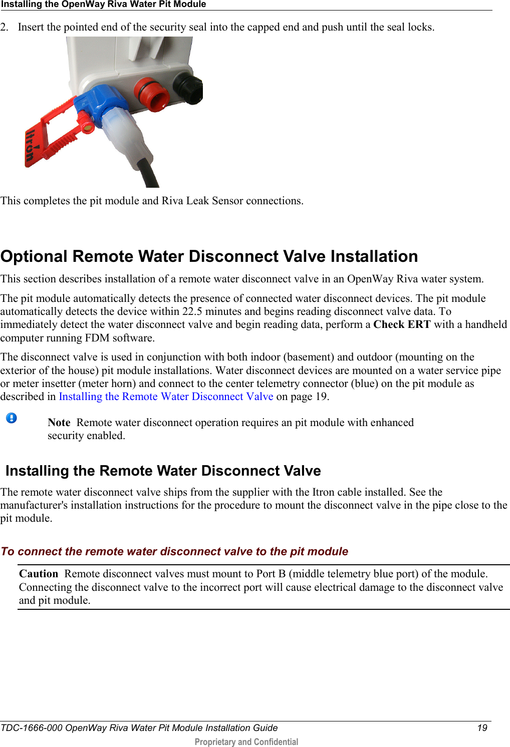
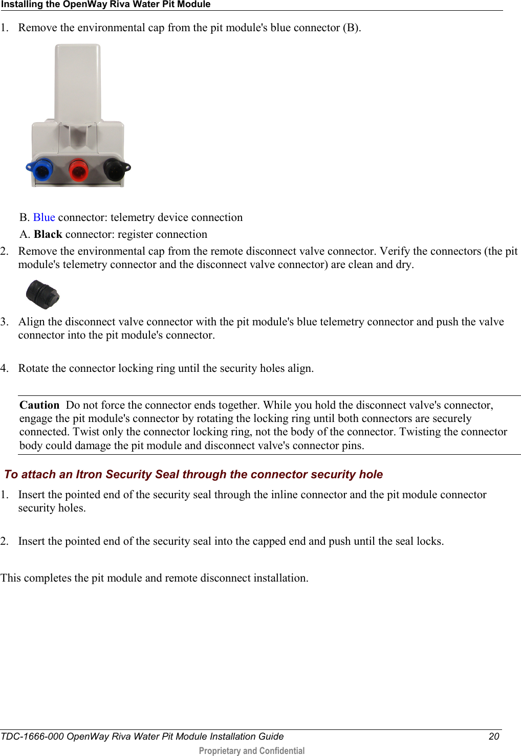
Itron RIVAW AMR transceiver device for utility meters User Manual OpenWay Riva Water Pit Module Installation Guide
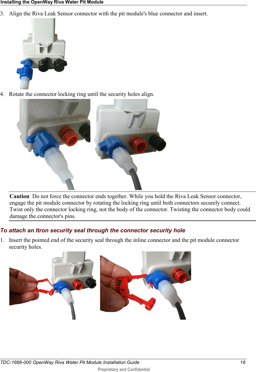
Itron Inc AMR transceiver device for utility meters OpenWay Riva Water Pit Module Installation Guide
Itron >
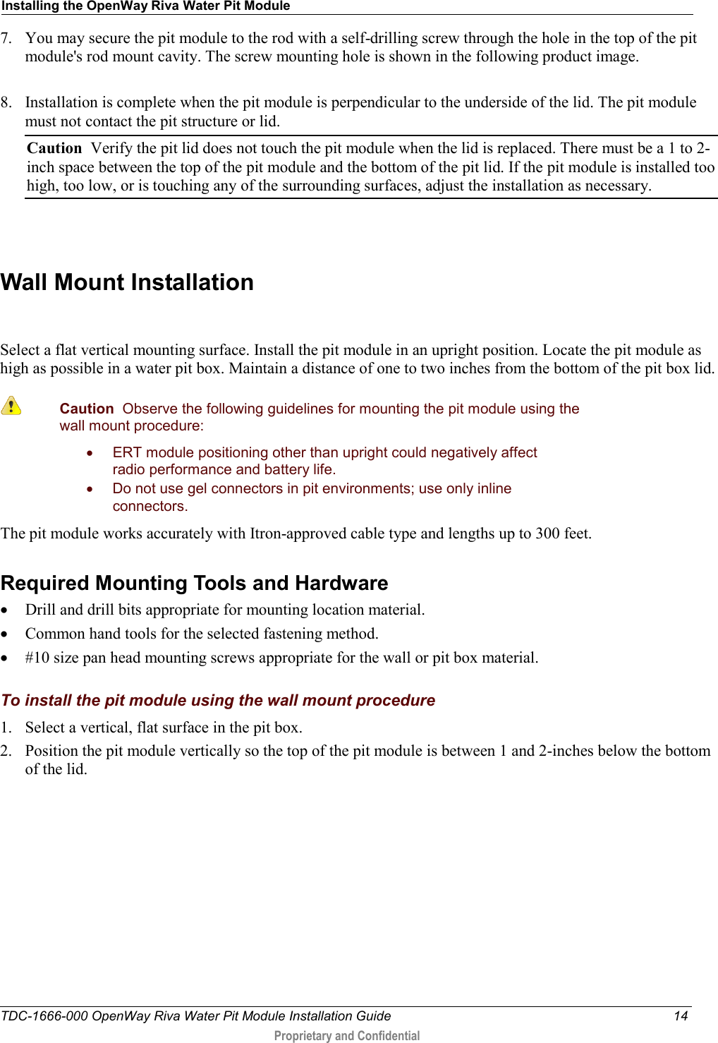
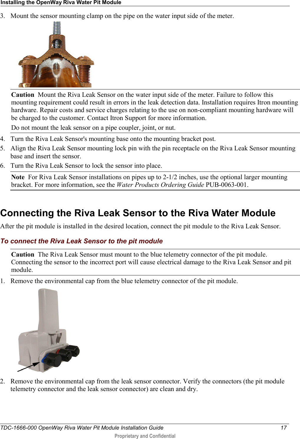
Users Manual