Itron RIVAW AMR transceiver device for utility meters User Manual OpenWay Riva Water Pit Module Installation Guide
Itron Inc AMR transceiver device for utility meters OpenWay Riva Water Pit Module Installation Guide
Itron >
Users Manual

Water Solutions
OpenWay Riva Water Pit Module Installation
Guide
TDC-1666-000

TDC
-1666-000 OpenWay Riva Water Pit Module Installation Guide ii
Proprietary and Confidential
Identification
OpenWay Riva Water Pit Module Installation Guide
26 September 2016 TDC-1666-000
OpenWay Riva Water Pit Module
Copyright
© 2016 Itron, Inc. All rights reserved.
Confidentiality Notice
The information contained herein is proprietary and confidential and provided subject to the condition that (i) it is held in confidence except to the extent required otherwise by law and (ii) it is
used only for the purposes described herein. Any third party given access to this information is similarly bound in writing.
Compliance Statement
This device complies with Part 15 of the FCC Rules. These limits are designed to provide reasonable protection against harmful interference in a residential installation. Operation is subject to
the following two conditions:
• This device may not cause harmful interference.
• This device must accept any interference that may cause undesirable operation.
This device must be permanently mounted such that it retains a distance of 20 centimeters (7.9 inches) from all persons in order to comply with FCC RF exposure levels.
This equipment has been tested and found to comply with the limits for a Class B digital device, pursuant to Part 15 of the FCC Rules. These limits are designed to provide reasonable
protection against harmful interference in a residential installation. This equipment generates, uses, and can radiate radio frequency energy and, if not installed and used in accordance with the
instructions, may cause harmful interference to radio communications. However, there is no guarantee that interference will not occur in a particular installation.
If this equipment does cause harmful interference to radio or television reception, which can be determined by turning the equipment off and on, the user is encouraged to try to correct the
interference by one or more of the following measures:
•Reorient or relocate the receiving antenna.
•Increase the separation between the equipment and receiver.
•Connect the equipment into an outlet on a circuit different from that to which the receiver is connected.
•Consult the dealer or an experienced radio or TV technician for help.
The RIVAW has not been authorized as required by the rules of the INNOVATION, SCIENCE AND ECONOMIC DEVELOPMENT of CANADA and should not be operated in Canada.
Trademark Notice
Itron is a registered trademark of Itron, Inc.
All other product names and logos in this documentation are used for identification purposes only and may be trademarks or registered trademarks of their respective companies.
Warning To prevent ignition of flammable or combustible atmospheres, disconnect power before servicing.
Warning Follow these procedures to avoid injury to yourself or others:
•The lithium battery may cause a fire or chemical burn if it is not disposed of properly.
•Do not recharge, disassemble, heat above 100° Celsius (212° Fahrenheit), crush, expose to
water, or incinerate the lithium battery. Fire, explosion, and severe burn hazard.
•Keep the lithium battery away from children.
•Replace the lithium battery only with batteries meeting Itron specifications. Any other battery may
cause a fire or explosion.
Warning ELECTROMAGNETIC COMPATIBILITY
Use only approved accessories with this equipment. Unapproved modifications or operation beyond or in conflict
with these instructions for use may void authorization by the authorities to operate the equipment.
Warning This unit cannot be modified and is not repairable. Attempts to modify or repair this device will void the
warranty.
Warning Internal circuit card components can be sensitive to electrostatic discharge. Before installation,
discharge electrostatic buildup by touching a metal water pipe or other earth-grounded metal object prior to
touching the meter body, register housing, or Riva module.
Warning Water modules contain sensitive electronic components which can be damaged if the module is
dropped from heights greater than 36 inches. Product warranty coverage is contingent on not exceeding this drop
height limitation.
Transportation Classification
The Federal Aviation Administration prohibits operating transmitters and receivers on all commercial aircraft. When powered, water modules are considered operating transmitters and
receivers and cannot be shipped by air. All product returns must be shipped by ground transportation to Itron.
Suggestions
If you have comments or suggestions on how we may improve this documentation, send them to TechnicalCommunicationsManager@itron.com
If you have questions or comments about the software or hardware product, contact Itron Technical Support:
Contact
•Internet: www.itron.com
•E-mail: support@itron.com
•Phone: 800 487 6602

TDC
-1666-000 OpenWay Riva Water Pit Module Installation Guide iii
Proprietary and Confidential

TDC
-1666-000 OpenWay Riva Water Pit Module Installation Guide v
Proprietary and Confidential
Before You Begin ........................................................................................................ vii
Document Conventions ..................................................................................................................... vii
Document Purpose ............................................................................................................................ vii
How This Document is Organized ..................................................................................................... vii
Related Documents .......................................................................................................................... viii
About the OpenWay Riva Pit Module ........................................................................... 1
OpenWay Riva Water Pit Module Description .................................................................................... 1
Itron Security Manager (ISM) .............................................................................................................. 2
Enabling OpenWay Riva Water Pit Module Security ................................................................ 2
Battery Life .......................................................................................................................................... 2
OpenWay Riva Water Pit Module Transmission Modes ..................................................................... 2
OpenWay Riva Water Pit Module Operating Modes ........................................................................... 3
Error/Warning Flags .................................................................................................................. 3
Initializing, Connecting, and Programming the OpenWay Riva Water Pit Module .. 5
OpenWay Riva Water Pit Module Start-up .......................................................................................... 5
Programming the Pit Module ............................................................................................................... 5
Connecting to a Meter Register Using the Inline Connector ............................................................... 5
Connecting the OpenWay Riva Water Pit Module to a Remote Meter Register ................................. 5
Connecting the Pit Module to a Remote Meter Register ..................................................................... 7
Verifying Pit Module Operation............................................................................................................ 7
Installing the OpenWay Riva Water Pit Module .......................................................... 9
Pit Module Mounting Accessories ....................................................................................................... 9
Pit Modules with Integral Connectors ................................................................................................ 10
Through Lid Installation ..................................................................................................................... 10
Through Lid Mount Required Tools and Hardware................................................................. 10
Rod Mount Installation ....................................................................................................................... 12
Required Tools and Hardware ................................................................................................ 12
Wall Mount Installation ...................................................................................................................... 14
Required Mounting Tools and Hardware ................................................................................ 14
Optional Riva Leak Sensor Installation ............................................................................................. 16
Riva Leak Sensor Installation Equipment ............................................................................... 16
Pipe Preparation ..................................................................................................................... 16
Connecting the Riva Leak Sensor to the Riva Water Module ................................................ 17
Optional Remote Water Disconnect Valve Installation ..................................................................... 19
Installing the Remote Water Disconnect Valve ....................................................................... 19
Using the Itron Cable Armor .............................................................................................................. 21
Required Materials .................................................................................................................. 21
Contents

Contents
TDC
-1666-000 OpenWay Riva Water Pit Module Installation Guide vi
Proprietary and Confidential
Using an Inline Connector .......................................................................................... 23
Troubleshooting .......................................................................................................... 25

TDC
-1666-000 OpenWay Riva Water Pit Module Installation Guide vii
Proprietary and Confidential
Document Conventions
Convention
Example
Itron product part numbers are noted in
parentheses.
To install the pit module (ERW-1601-XXX), do the following steps.
Hypertext links are in blue. See How The Document is Organized for document structure information.
Note A Note indicates neutral or positive information that stresses or supplements important points of
the main text. A note supplies information that may apply only in special cases.
Caution A Caution advises users that failure to take or avoid a specified action could result in a loss of
data.
Warning A Warning advises users that failure to take or avoid a specified action could result in
physical harm to the user or the hardware.
Document Purpose
This document provides the installation instructions for the OpenWay Riva Water Pit Module and details the
various mounting options.
How This Document is Organized
This document is organized into the following chapters:
Chapter
Description
1. Before You Begin
Information about this publication.
2. About the OpenWay Riva Water Pit Module Overview of pit module installation.
3. Initializing, Connecting, and Programming the Pit Module Instructions to initialize, program, and connect the pit module to the water
register/meter.
4. Installing the OpenWay Riva Water Pit Module
Step-by-step installation instructions for:
• Through lid mount
• Rod mount
• Wall mount
• Optional Riva Leak Sensor installation
• Optional remote water disconnect valve installation
Appendix A Using the Itron Cable Armor Instructions for installing the optional cable armor.
Appendix B Using an Inline Connector Instructions for installing an inline connector.
Appendix C Troubleshooting Troubleshooting pit module operation.
Before You Begin

Before You Begin
TDC
-1666-000 OpenWay Riva Water Pit Module Installation Guide viii
Proprietary and Confidential
Related Documents
Document Description
Itron Part Number
OpenWay Riva Water Remote Module Installation Guide TDC-1687-XXX
OpenWay Collection Manager Operational Guidelines
OpenWay Riva Events and Exceptions Reference Guide
Field Deployment Manager Endpoint Tools Mobile Application Guide TDC-0934-XXX
Field Deployment Manager Field Representative's Guide
TDC-0936-XXX
900 MHz Belt-Clip Radio User's Guide
TDC-0889-XXX
FC300 Getting Started Guide TDC-0898-XXX
FC200 Series Getting Started Guide TDC-0598-XXX
Water Module Products Ordering Guide
PUB-0063-001
Water Meter and Telemetry Module Compatibility List
PUB-0063-002
mlogonline™ Network Leak Monitoring System User Guide TDC-0792-XXX
Note XXX designates the document revision and is subject to change without
notice.

TDC
-1666-000 OpenWay Riva Water Pit Module Installation Guide 1
Proprietary and Confidential
OpenWay Riva water modules are high-power radio frequency transmitting modules that attach to water
registers/meters to collect consumption usage and tamper data. The OpenWay Riva water module transmits
the meter/register data to a collection device which in turn transfers the information to the utility's customer
billing system. The OpenWay Riva water module operates in a Mobile/Handheld environment. The OpenWay
Riva Water Pit Module reports 9-digit register data with Mobile SCM+. Additionally, the OpenWay Riva
water module may be programmed to truncate up to three of the meter/register's least significant digits.
The OpenWay Riva water modules ship from the factory in Factory Mode which prevents unwanted radio
transmissions during transit. After installation and programming, the OpenWay Riva Water Pit Modules
acquire and transmit meter register data in accordance with the selected pit module parameter settings.
The OpenWay Riva Water Pit Modules support protocols for a variety of meter manufacturer's registers. Refer
to the Water Meter and Telemetry Module Compatibility List (PUB-0063-002), for the list of supported meters
and registers.
OpenWay Riva Water Pit Modules feature the following capabilities:
• Leak Detection and Reverse Flow Detection. OpenWay Riva water modules feature robust algorithms
that provide Leak and Reverse Flow Detection.
• (Optional) OpenWay Riva Leak Sensor
• The optional Riva Leak Sensor analyzes water flow sound patterns to detect water leaks. Leak sensor
analysis data is uploaded to the mlogonline Network Leak Monitoring online portal. Systems with
optional Riva Leak Sensor devices access leak information through a utility-specific, secure
mlogonline portal (for more information, see the mlogonline Network Leak Monitoring System User
Guide TDC-0792-XXX).
• (Optional) Telemetry Devices
• Optional remote water disconnect valves provides water utilities with a non-intrusive means of
managing customer disconnects and reconnects that traditionally required on-site visits. The remotely-
controlled disconnect valve helps lower the utility's costs by eliminating routine move-in/move-out
service calls.
Note Remote water disconnect operation requires an OpenWay Riva water module with enhanced
security enabled. To learn more about enabling enhanced security, see the Field Deployment
Manager Endpoint Tools Mobile Application Guide (TDC-0934-XXX).
OpenWay Riva Water Pit Module Description
Description
Itron Part Number
OpenWay Riva Water Pit Module ERW-1601-001
Note The OpenWay Riva Water Pit Module works accurately with cable lengths up
to 300 feet.
CHAPTER 1
About the OpenWay Riva P
it Module

About the OpenWay Riva Pit Module
TDC
-1666-000 OpenWay Riva Water Pit Module Installation Guide 2
Proprietary and Confidential
Itron Security Manager (ISM)
Users have the option of enabling enhanced security in OpenWay Riva Water Pit Modules. Itron Security
Manager (ISM) is a feature of the OpenWay Riva system that ensures certain pit module commands are issued
through secure radio communications between the handheld computer, Mobile Collector, or OpenWay
system.
There are two fundamental security processes used in the OpenWay Riva system to ensure confidentiality and
validity of secured commands.
• Authentication. Authentication is the process of confirming that an artifact is genuine or valid.
Authentication in the OpenWay Riva Water Pit Module is the process of verifying a request is from a
valid source and in its original form.
• Encryption. Encryption is the process of transforming information to make it unreadable to anyone who
does not have a valid security key. There are two types of encryption, symmetric and asymmetric.
Symmetric encryption uses a shared key to decrypt or encrypt information. Asymmetric encryption uses a
private key to encrypt and a public key to decrypt. Data transmissions over the network are protected
using AES-256 encryption.
Enabling OpenWay Riva Water Pit Module Security
Each pit module ships from the Itron factory with a utility factory security key. The presence of this utility
factory key does not enable security. To utilize the module's security feature, the installer must use an Itron
programming device (FC300) that is configured with the corresponding security key for that particular pit
module. Initial key exchange commands are secured using the utility factory key. For more information about
programming the pit module, see the FDM Endpoint Tools Mobile Application Guide (TDC-0934).
Battery Life
The OpenWay Riva Water Pit Module is powered by two non-replaceable, long-life lithium batteries, and has
an expected battery life of 20 years when the pit module operates in default mobile operating mode. If the pit
module is programmed for hard to read mobile mode, the battery life is reduced to 12 years. To proactively
indicate the battery has reached a <10% useful battery life, a Low Battery Flag is set to indicate a low battery
warning and alert the utility of an impending battery failure.
OpenWay Riva Water Pit Module Transmission Modes
The OpenWay Riva Water Pit Module can be set to transmit in Standard Mobile/Handheld Mode (factory
default setting), Mobile High Power Mode, Hard-to-Read, or Audit Mode.
• Mobile and Handheld Mode. In Mobile and Handheld Mode:
• the pit module transmits a medium-powered SCM+ message every 10 seconds.
• (Optional) Mobile High Power Mode. The pit module transmits a high-powered SCM+ RF message
every 60 seconds.
• (Optional) Hard to Read Mobile Mode. The pit module transmits a high-powered SCM+ RF message
every 30 seconds. The hard-to-read Mobile Mode should only be used for exceptionally hard-to-read
locations as this mode reduces battery life significantly.
Note The OpenWay Riva Water Pit Module's battery life is significantly affected in hard to read mobile
mode.

About the OpenWay Riva Pit Module
TDC
-1666-000 OpenWay Riva Water Pit Module Installation Guide 3
Proprietary and Confidential
• Audit Mode. Audit mode reduces the normal read latency time associated with standard modes of
operation and is often used after initial installation. This mode is useful in installations where the normal
bubble-up rate is very slow. Audit Mode remains active for 30 days and then reverts to the initial
programmed mode. Audit Mode is intended to be used once.
An FCC license is not required to read OpenWay Riva Water Pit Modules.
OpenWay Riva Water Pit Module Operating Modes
1. Factory mode
• Pit Modules ship from the factory in Factory Mode.
• The pit module's transmitter is off.
• The pit module's receiver bubbles-up to listen for a programming command.
• pit modules attempt to read the register every hour.
• Last Good Read and Extended Tamper Flags may be set when a register is not connected.
• If the pit module reads a connected register, the pit module automatically moves to Run Mode.
2. Run mode
• Pit Module normal operation mode.
• The OpenWay Riva Water Pit Module transmitted message is dependent on its factory settings or
setting programmed with FDM for standard consumption messages (SCM+).
For SCM+ (Mobile), the pit module default bubble-up rate is 10 seconds.
3. Meter manufacturer quiet mode
• Meter manufacturers can configure the pit module for quiet mode after initializing and direct
mounting the pit module in the factory.
• The pit module awakens from quiet mode and enters run mode in one of two ways:
1. The pit module detects consumption at the top of the hour (last hourly interval >1 or <-1).
2. The pit module receives a two-way command (for example, a Read ERT using FDM software).
Error/Warning Flags
Register Error Detected. Register Error Detected indicates that the pit module is not communicating with the
register/meter. The tamper flag automatically clears after the pit module receives a successful read from the
register.
Note The Register Error Detected flag may be an indicator of a damaged register.
Extended Tamper Flag (retrievable with two-way communication).
Low Battery Warning. The pit modules include a battery life estimator. The estimator is based on the
number of data packets sent at the various power levels and the age (self-discharge) of the pit module. The
low battery warning allows the utility to easily identify which water modules are nearing end-of-life in a
mixed population and gives the utility the opportunity to schedule replacement.
Note The low battery warning is a single flag that is set when the battery has less than 10% remaining
capacity, which typically corresponds to 2 years of battery life remaining. Battery life is evaluated daily at
midnight.

About the OpenWay Riva Pit Module
TDC
-1666-000 OpenWay Riva Water Pit Module Installation Guide 4
Proprietary and Confidential
Register Error Flag
• The Register Error flag sets if the Register Error Detected flag is active for 24 hours.
• The Register Error Flag remains active for 40 days in Mobile mode.

TDC
-1666-000 OpenWay Riva Water Pit Module Installation Guide 5
Proprietary and Confidential
This chapter provides the instructions to program and connect the pit module.
OpenWay Riva Water Pit Module Start-up
The pit module automatically:
• Detects the connected register type at the top of the hour, exits Factory Mode, and enters Run Mode.
• Detects an Itron Riva Leak Sensor.
OpenWay Riva Water Pit Module programming is required to:
• Change the operation mode
• Enter a utility ID or lock type.
• To enter an E-Coder 8-digit driver.
• Commission security
Itron strongly recommends performing a Check ERT with a handheld computer running FDM to verify the
pit module is operating correctly after installation. Performing a Check ERT will:
• Generate an immediate register read.
• Verify communication with the Riva Leak Sensor.
• Check for tamper flags.
Programming the Pit Module
Programming the pit module requires one of the following handheld computers running Field Deployment
Manager (FDM) version 4.0 or later.
• FC200SR handheld computer (Itron part number FC2-0005-004 or FC2-0006-004)
• FC300 with SRead
For normal activation, connect the pit module to the water meter register and program the pit module using
FDM.
Connecting to a Meter Register Using the Inline Connector
The inline connector system provides easier general maintenance or system troubleshooting (see Using an
Inline Connector on page 23).
Connecting the OpenWay Riva Water Pit Module to a Remote
Meter Register
Order the 25-foot inline connector extension cable assembly (CFG-0151-401) to extend the cable of the pit
module.
CHAPTER 2
Initializing, Connecting, and Programming the OpenWay Ri
va
Water Pit Module

Initializing, Connecting, and Programming the OpenWay Riva Water Pit Module
TDC
-1666-000 OpenWay Riva Water Pit Module Installation Guide 6
Proprietary and Confidential
Connect the pit module cable to the register according to the following table.
Register Manufacturer
Pit Module wire color
Red
(data)
Black
(power/clock)
White
(ground)
Register screw terminal
Badger ADE
E Series
HR E LCD
HR E Mechanical
Green Red Black
Badger M5000 Mag Meter
Terminal: Out 1+ Terminal: Out 1-
Terminal: Out 1+
Elster AMCO InVision
Scancoder Red Green Black
Elster AMCO SM 700 (Severn Trent), Q200
Green Red Black
Elster AMCO evoQ4 Mag Red White Black
Itron (Actaris) Cyble Coder Green Red Black
Kamstrup flowIQ2100 Green Red Black
MasterMeter AccuLinx
Octave Green Red Black
Metron Farnier Green Red Black
Mueller (Hersey) Translator, SSR
Green Red Black
Sensus ECR
ICE
iPERL
SRII
OMNI
Green Red Black
Neptune ProRead, ProRead AutoDetect
E-Coder
ARB-V
Red Black Green
Performance ETR Green Red Black
RG3 Tomahawk
Green Red Black
Siemens Mag meter
Mag8000CT-7ME6820
Mag8000-7ME6810
92 91 93

Initializing, Connecting, and Programming the OpenWay Riva Water Pit Module
TDC
-1666-000 OpenWay Riva Water Pit Module Installation Guide 7
Proprietary and Confidential
Connecting the Pit Module to a Remote Meter Register
Connect pit module cable to the register according to the following table.
Pit Module Connections
Register Manufacturer
Pit Module wire color
Red
(signal)
Black
(common)
White
(tamper)
Register screw color designator
Badger RTR (3-wire)
Red Black Green/bare
Badger RTR (2-wire)
Red Black No connection*
Badger M5000 Mag Meter Out 1+ Out 2- Out 1+
Elster Digital Black Green Red
Elster V100T Black Red Blue
Itron (Actaris) Flostar (2-wire)
Cyble Sensor Either wire Remaining wire must be connected to both
pit module wires
Krohne IFC
Term B Term H Term B
RG3 Tomahawk
Green Black Green
Sensus PMM Red Black Bare
Verifying Pit Module Operation
Use one of the following handheld computers to verify consumption:
• FC200SR handheld computer (Itron part number FC2-0005-004 or FC2-0006-004)
• FC300 with SRead
Notes
• Each handheld radio requires special setup and configuration parameters to successfully read
and program the pit module. Refer to the respective meter reading application for specific
instructions.
• When comparing the actual register value to that reported by the pit module, please keep in
mind the ERT module's consumption value is updated once an hour when it is in Run Mode.
Caution Verifying the OpenWay Riva Water Pit Module operation requires an FC200SR or and
FC300 handheld computer running FDM v. 4.0 or higher. Legacy Itron handheld programming
devices cannot read the pit modules.

Initializing, Connecting, and Programming the OpenWay Riva Water Pit Module
TDC
-1666-000 OpenWay Riva Water Pit Module Installation Guide 8
Proprietary and Confidential

TDC
-1666-000 OpenWay Riva Water Pit Module Installation Guide 9
Proprietary and Confidential
Install the pit module using one of the following methods:
Pit Module Mounting Options
Through-Lid The pit module mounts in lids with hole sizes from 1-3/4 inches to 2-inches. Installation requires the Pit
Lid Mounting Kit.
Rod mount*
The pit module mounts on a 1/2-inch outside diameter rod.
Wall mount* The pit module mounts to a wall or other vertical surface.
* Important Rod and wall mount installations require the Itron Pit Lid Mounting Kit.
For water pit boxes, the type of installation method is based on three factors: the location of the meter in the
pit box, the lid material, and the current lid configuration. Itron recommends mounting the pit module in pit
boxes with in plastic lids (or other composite materials) for optimum network performance. The pit modules
are temperature rated from -20º C to +60º C. Do not install the pit module in locations that may exceed the
temperature rating.
Caution Pit module positioning other than upright could negatively affect radio performance and
battery life.
Warning Pit modules contain sensitive electronic components which can be damaged if the
module is dropped from heights greater than 36 inches. Product warranty coverage is contingent
on not exceeding this drop height limitation.
Warning Internal circuit card components are extremely sensitive to electrostatic discharge. Be
careful not to touch any part of the meter body, register housing, or Riva module prior to
discharging any static buildup on your person. To discharge yourself, touch a grounded metal
object such as the metal water pipe or an earth-grounded metal structure.
Pit Module Mounting Accessories
Pit Module Mounting Accessories
Accessory
Part Number
Riva Rod Mount Adapter MLD-1601-007
Riva Pit Lid Mounting Kit CFG-1601-001
Cable Armor (see Appendix C for field retrofit installation instructions)
5 foot cable thin-insulation (with protective cover and cable armor)
5 foot cable thick-insulation (with protective cover and cable armor)
5 foot cable armor for field retrofit
CFG-0151-006SS
CFG-0151-010SS
FAB-1302-001
pit module Universal Environmental Cap MSC-0019-008
Itron Security Seal
MSC-0018-001
Caution Shield unconnected pit module ports on field installed modules with protective
environmental covers. Do not leave an exposed connector in the field. Environmental caps
employ multiple seals to increase cap life.
CHAPTER 3
Installing the OpenWay Riva Water Pit Module
Installing the OpenWay Riva Water Pit Module
TDC
-1666-000 OpenWay Riva Water Pit Module Installation Guide 10
Proprietary and Confidential
Pit Modules with Integral Connectors
If pit modules with integral connectors (ERW-1601-00X) and the registers are not installed at the same time,
secure the protective environmental connector cover on the pit module using an Itron Security Seal (Itron part
number MSC-0018-001). Cable ties are not shipped with the pit module, but can be ordered from Itron. Use
the protective cover (on the pit module side) in the field for up to one year.
Warning If a three-port pit module is installed but the telemetry device is not
attached, the environmental cap (MSC-0019-008) must remain in place on the
blue connector (telemetry) to protect the connector from damage.
To install a Security Seal through the protective connector cover
1. Align the protective cover and connector security seal holes.
2. Insert the security seal pointed end through the security holes in the connector and protective cover.
3. Insert the pointed end of the security seal into the cap end and push until the seal locks.
Through Lid Installation
This section provides instructions to mount the pit module in a pit lid with a drilled, round 1-3/4-inch, 1-7/8-
inch, or 2-inch hole.
Through Lid Mount Required Tools and Hardware
This mounting method requires the Pit Lid Mounting Kit.
Pit Lid Mounting Kit (CFG-1601-001)
Note The Pit Lid Mounting Kit is not intended for applications involving vehicular traffic.
Installing the OpenWay Riva Water Pit Module
TDC
-1666-000 OpenWay Riva Water Pit Module Installation Guide 11
Proprietary and Confidential
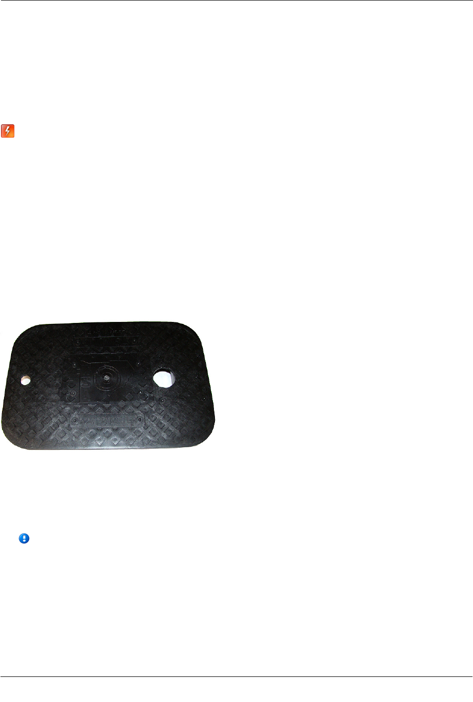
This section provides the instructions to install the pit module in a pit lid with a hole using the Pit Lid
Mounting Kit (CFG-1300-004). Verify you have the following items to complete the installation.
A Retainer clip
B Pit lid with a pre-drilled hole
C Retainer clip collar
D OpenWay Riva Water Pit
Module
To install the module in lids with holes using the Pit Lid Mounting Kit
1. Insert the retainer clip into the pit lid hole with the convex surface on the top of the pit lid.
2. From the bottom side of the lid, screw on the threaded retainer clip collar until the beveled top rests
against the pit lid.
Note Ensure the beveled edge of the clip collar is toward the top of the pit lid.
3. Align and insert the retainer clip tab into the retainer clip receptacle on the pit module housing.
4. Verify the clip locks into place in the housing.
Caution Carefully align the pit module through lid assembly. If the assembly is improperly aligned, the
pit lid may not close.
Pit lid mounting installation is complete.

Installing the OpenWay Riva Water Pit Module
TDC
-1666-000 OpenWay Riva Water Pit Module Installation Guide 12
Proprietary and Confidential
Rod Mount Installation
Important Rod mount installation requires the Rod Mount Adapter. For more information, see Pit
Module Mounting Accessories on page 9.
OpenWay Riva Water Pit Modules can mount below the pit lid on a customer-supplied 1/2-inch diameter rod.
The example installation described in this section uses a fiberglass rod. For more information, visit
www.itron.com and reference the Water Meter and Telemetry Device Compatibility List (PUB-0063-002).
Warning The rod installation area must be free from other pipes, wires, or facilities that
may be damaged by driving a rod into the ground.
Caution You must follow local codes when using the rod mount installation method. Failure
to use a 1/2-inch rod and follow instructions may result in an unreliable installation.
Caution Observe the following guidelines for mounting the pit module using the rod mount
procedure:
• Pit module positioning other than upright could negatively affect radio
performance and battery life.
Required Tools and Hardware
• Hammer
• 1/2-inch outside diameter rod (you may use either a square or round rod)*
• Tape measure
• Rod-driving tool (optional)
• Rod cutting tool
*Itron offers 12" (OEM-1006-001), 18" (OEM-1006-002), or 36" (OEM-1006-005) fiberglass mounting rods.
Minimum order quantity is 100. For more information, see the Itron Water Products Ordering Guide (PUB-
0063-001).
To install the pit module on a rod
1. Remove the pit lid. Inspect the area to make sure there are no buried cables, pipes, or other obstructions.
2. Measure the pit box depth from the top of the lip (where the lid will rest) to the bottom of the pit. Be sure
to measure the depth at the point where you will drive the rod into the ground.
3. Add 12 inches to the pit box depth measurement taken in step 2. The resulting total represents the
minimum length of rod needed. Soil types and moisture conditions may require longer rod lengths to
ensure the pit module is well supported and remains vertical.

Installing the OpenWay Riva Water Pit Module
TDC
-1666-000 OpenWay Riva Water Pit Module Installation Guide 13
Proprietary and Confidential
4. Without touching the meter body or adjacent pipes, position the rod as close to the center of the pit as
possible. Drive the rod into the ground. Ensure the rod remains vertical.
Note The rod shown has an end cap to protect the rod while driving it into the ground.
5. Drive the rod into the ground so the top of the rod is approximately 3-1/2 inches below the bottom of the
pit lid.
• If you cannot drive the rod in enough to equal the necessary spacing, cut the remaining rod length to
the proper height using an abrasive cut-off tool.
Caution Cutting fiberglass creates dust particles. Practice proper safety precautions when using cut-off
tools to prevent exposure to fiberglass dust particles.
• If the rod is the correct depth but remains loose in the soil, replace the rod with a longer version.
6. The top of the rod must be 3-1/2 inches below the bottom of the lid. Place the Riva module on the rod.
Completely insert the rod into the pit module's rod mount hole. Do not force the pit module onto the rod.
If the pit module does not slide freely on the rod, remove the pit module and examine the pit module rod
hole and rod for burrs or obstructions.

Installing the OpenWay Riva Water Pit Module
TDC
-1666-000 OpenWay Riva Water Pit Module Installation Guide 14
Proprietary and Confidential
7. You may secure the pit module to the rod with a self-drilling screw through the hole in the top of the pit
module's rod mount cavity. The screw mounting hole is shown in the following product image.
8. Installation is complete when the pit module is perpendicular to the underside of the lid. The pit module
must not contact the pit structure or lid.
Caution Verify the pit lid does not touch the pit module when the lid is replaced. There must be a 1 to 2-
inch space between the top of the pit module and the bottom of the pit lid. If the pit module is installed too
high, too low, or is touching any of the surrounding surfaces, adjust the installation as necessary.
Wall Mount Installation
Select a flat vertical mounting surface. Install the pit module in an upright position. Locate the pit module as
high as possible in a water pit box. Maintain a distance of one to two inches from the bottom of the pit box lid.
Caution Observe the following guidelines for mounting the pit module using the
wall mount procedure:
• ERT module positioning other than upright could negatively affect
radio performance and battery life.
• Do not use gel connectors in pit environments; use only inline
connectors.
The pit module works accurately with Itron-approved cable type and lengths up to 300 feet.
Required Mounting Tools and Hardware
• Drill and drill bits appropriate for mounting location material.
• Common hand tools for the selected fastening method.
• #10 size pan head mounting screws appropriate for the wall or pit box material.
To install the pit module using the wall mount procedure
1. Select a vertical, flat surface in the pit box.
2. Position the pit module vertically so the top of the pit module is between 1 and 2-inches below the bottom
of the lid.

Installing the OpenWay Riva Water Pit Module
TDC
-1666-000 OpenWay Riva Water Pit Module Installation Guide 15
Proprietary and Confidential
3. Mark the location of the top mounting hole.
4. Drill a pilot hole in the pit box wall. Follow the screw manufacturer's recommendation for the pilot hole
size.
5. For concrete-type pit boxes, it may be necessary to use a screw anchor. Choose an anchor appropriate for
a #10 pan head screw.
Caution Do not over-tighten the mounting screws. Over-tightening the mounting screws may break the
pit module mounting tabs.
6. Start a screw into the pilot hole. Using the top hole of the pit module, set the pit module over the screw
head and slide it down so the screw is now at the top of the notch. Carefully tighten the screw until snug.
Over-tightening the mounting screw could damage the pit module housing.
Note If the mounting location requires a screw anchor, mark the location of the bottom anchor and
remove the pit module. Drill the required mounting hole, insert the anchor, and re-attach the pit module.
7. Holding the pit module in the upright position, drill the second pilot hole. Use the bottom mounting hole
as a template.
Caution Any pit module position other than upright may negatively affect radio performance and battery
life.
8. Screw the bottom screw into the pilot hole until snug. Do not over-tighten the mounting screw.

Installing the OpenWay Riva Water Pit Module
TDC
-1666-000 OpenWay Riva Water Pit Module Installation Guide 16
Proprietary and Confidential
Optional Riva Leak Sensor Installation
This section describes installation of the OpenWay Riva Leak Sensor in a OpenWay Riva Water Pit Module
system.
The pit module stores 20 days of Riva Leak Sensor data. On the 21st day, the pit module begins to write over
stored data in a first in, first out manner.
The pit module automatically detects the presence of connected Riva Leak Sensor. The pit module
automatically detects the sensor within 22.5 minutes and begins reading the sensor data. To immediately
detect the Riva Leak Sensor and begin reading data, perform a Check ERT with a handheld computer running
FDM software.
The Riva Leak Sensor is used in conjunction with both indoor (basement) and outdoor (mounting on the
exterior of the house) pit module installations. Riva Leak Sensors are mounted on a water service pipe or
meter insetter (meter horn) and connect to the telemetry connector on the pit module. For more information,
see To connect the Riva Leak Sensor to the pit module on page 17. The mounting bracket shipped with the
Riva Leak Sensor accommodates an (up to) 1-1/2-inch OD pipe. An optional mounting bracket is available for
pipe sizes (up to 2 1/2-inch OD).
Riva Leak Sensor Installation Equipment
For a list of Riva Leak Sensor installation equipment, refer to the Water ERT Products Ordering Guide PUB-
0063-001.
Warning When the pit module is installed but the telemetry device is not
attached, you must protect the blue port with the universal environmental cap
(MSC-0019-008). If you disconnect the telemetry device from the pit module, the
environmental cap must be replaced to protect the connector.
Pipe Preparation
Clean any dust or dirt from the pipe to facilitate direct contact with the Riva Leak Sensor surface.
To install the Riva Leak Sensor on a pipe or meter insetter
1. Select a mounting location within 5-feet of the pit module.
2. Verify the pipe’s mounting surface is free from dirt and debris.

Installing the OpenWay Riva Water Pit Module
TDC
-1666-000 OpenWay Riva Water Pit Module Installation Guide 17
Proprietary and Confidential
3. Mount the sensor mounting clamp on the pipe on the water input side of the meter.
Caution Mount the Riva Leak Sensor on the water input side of the meter. Failure to follow this
mounting requirement could result in errors in the leak detection data. Installation requires Itron mounting
hardware. Repair costs and service charges relating to the use on non-compliant mounting hardware will
be charged to the customer. Contact Itron Support for more information.
Do not mount the leak sensor on a pipe coupler, joint, or nut.
4. Turn the Riva Leak Sensor's mounting base onto the mounting bracket post.
5. Align the Riva Leak Sensor mounting lock pin with the pin receptacle on the Riva Leak Sensor mounting
base and insert the sensor.
6. Turn the Riva Leak Sensor to lock the sensor into place.
Note For Riva Leak Sensor installations on pipes up to 2-1/2 inches, use the optional larger mounting
bracket. For more information, see the Water Products Ordering Guide PUB-0063-001.
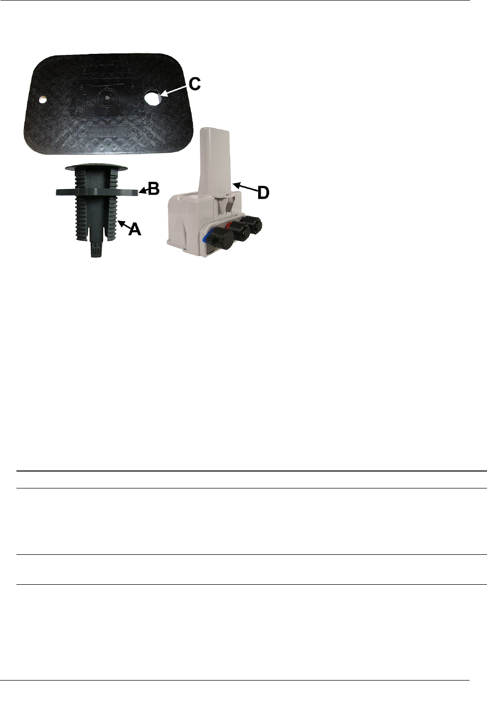
Connecting the Riva Leak Sensor to the Riva Water Module
After the pit module is installed in the desired location, connect the pit module to the Riva Leak Sensor.
To connect the Riva Leak Sensor to the pit module
Caution The Riva Leak Sensor must mount to the blue telemetry connector of the pit module.
Connecting the sensor to the incorrect port will cause electrical damage to the Riva Leak Sensor and pit
module.
1. Remove the environmental cap from the blue telemetry connector of the pit module.
2. Remove the environmental cap from the leak sensor connector. Verify the connectors (the pit module
telemetry connector and the leak sensor connector) are clean and dry.
Installing the OpenWay Riva Water Pit Module
TDC
-1666-000 OpenWay Riva Water Pit Module Installation Guide 18
Proprietary and Confidential
3. Align the Riva Leak Sensor connector with the pit module's blue connector and insert.
4. Rotate the connector locking ring until the security holes align.
Caution Do not force the connector ends together. While you hold the Riva Leak Sensor connector,
engage the pit module connector by rotating the locking ring until both connectors securely connect.
Twist only the connector locking ring, not the body of the connector. Twisting the connector body could
damage the connector's pins.
To attach an Itron security seal through the connector security hole
1. Insert the pointed end of the security seal through the inline connector and the pit module connector
security holes.

Installing the OpenWay Riva Water Pit Module
TDC
-1666-000 OpenWay Riva Water Pit Module Installation Guide 19
Proprietary and Confidential
2. Insert the pointed end of the security seal into the capped end and push until the seal locks.
This completes the pit module and Riva Leak Sensor connections.
Optional Remote Water Disconnect Valve Installation
This section describes installation of a remote water disconnect valve in an OpenWay Riva water system.
The pit module automatically detects the presence of connected water disconnect devices. The pit module
automatically detects the device within 22.5 minutes and begins reading disconnect valve data. To
immediately detect the water disconnect valve and begin reading data, perform a Check ERT with a handheld
computer running FDM software.
The disconnect valve is used in conjunction with both indoor (basement) and outdoor (mounting on the
exterior of the house) pit module installations. Water disconnect devices are mounted on a water service pipe
or meter insetter (meter horn) and connect to the center telemetry connector (blue) on the pit module as
described in Installing the Remote Water Disconnect Valve on page 19.
Note Remote water disconnect operation requires an pit module with enhanced
security enabled.
Installing the Remote Water Disconnect Valve
The remote water disconnect valve ships from the supplier with the Itron cable installed. See the
manufacturer's installation instructions for the procedure to mount the disconnect valve in the pipe close to the
pit module.
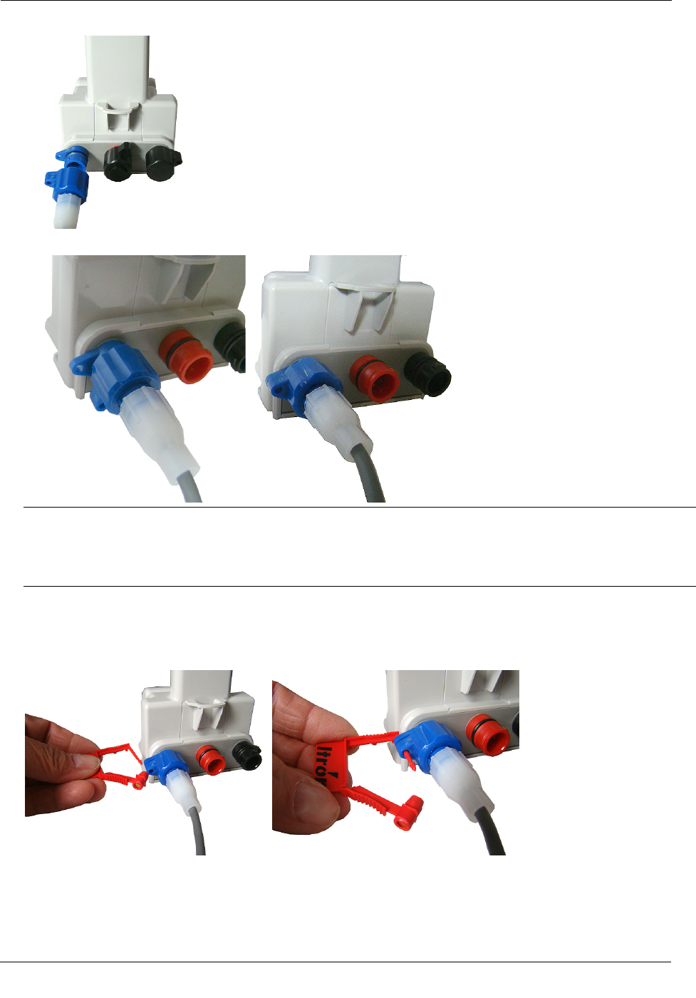
To connect the remote water disconnect valve to the pit module
Caution Remote disconnect valves must mount to Port B (middle telemetry blue port) of the module.
Connecting the disconnect valve to the incorrect port will cause electrical damage to the disconnect valve
and pit module.
Installing the OpenWay Riva Water Pit Module
TDC
-1666-000 OpenWay Riva Water Pit Module Installation Guide 20
Proprietary and Confidential
1. Remove the environmental cap from the pit module's blue connector (B).
B. Blue connector: telemetry device connection
A. Black connector: register connection
2. Remove the environmental cap from the remote disconnect valve connector. Verify the connectors (the pit
module's telemetry connector and the disconnect valve connector) are clean and dry.
3. Align the disconnect valve connector with the pit module's blue telemetry connector and push the valve
connector into the pit module's connector.
4. Rotate the connector locking ring until the security holes align.
Caution Do not force the connector ends together. While you hold the disconnect valve's connector,
engage the pit module's connector by rotating the locking ring until both connectors are securely
connected. Twist only the connector locking ring, not the body of the connector. Twisting the connector
body could damage the pit module and disconnect valve's connector pins.
To attach an Itron Security Seal through the connector security hole
1. Insert the pointed end of the security seal through the inline connector and the pit module connector
security holes.
2. Insert the pointed end of the security seal into the capped end and push until the seal locks.
This completes the pit module and remote disconnect installation.
TDC
-1666-000 OpenWay Riva Water Pit Module Installation Guide 21
Proprietary and Confidential
Using the Itron Cable Armor
This section describes the procedure for installing Itron cable armor in a field installation. The Itron cable
armor provides a layer or protection for the module's cable jacket. Itron cable armor is available in five-foot
sections.
Warning Itron cable armor is stainless steel and may have sharp edges. Use caution when you
are installing the cable armor.
Important If you remove the inline connector from the pit module to install the cable armor, you
must use an Itron handheld to reprogram the pit module using FDM Endpoint Tools. Perform a
Check Endpoint function (with FDM Endpoint Tools) after you reprogram the pit module to
verify communication with the meter register.
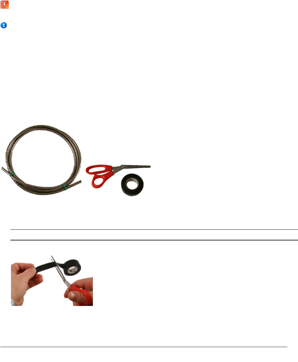
Required Materials
The following materials are required to install the Itron cable armor.
• 5-foot Itron cable armor
• Electrical tape
• (Optional) Scissors
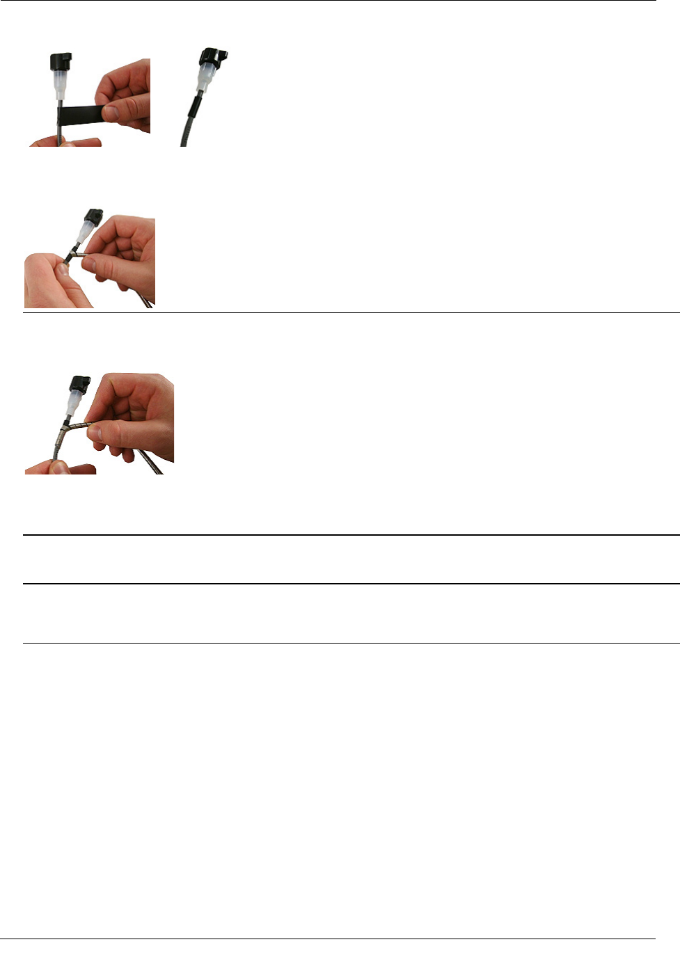
To install the Itron cable armor
1. Remove the pit module from the pit.
Note If it is possible in your field installation, keep the pit module connected to the register.
2. Cut a two to three inch strip of electrical tape.
APPENDIX A
Installing the OpenWay Riva Water Pit Module
TDC
-1666-000 OpenWay Riva Water Pit Module Installation Guide 22
Proprietary and Confidential
3. Wrap the entire piece of electrical tape around the pit module cable near the inline connector.
4. Beginning over the installed electrical tape, twist the Itron cable armor onto the pit module cable using a
right-handed twist.
Important You must twist—not wrap—the cable armor onto the pit module cable. Wrapping the cable
armor can cause the stainless steel jacket to warp.
Warning You must begin twisting the cable armor over portion of the cable protected by the electrical
tape. If you do not begin to twist the cable armor over the protected portion of the pit module cable, a cut
cable could cause an pit module/register communication failure.
5. Continue to twist the cable armor onto the pit module cable until the cable armor covers the entire cable.
Warning You must continue to twist the cable armor onto the cable protected by the electrical tape. If
you do not twist the cable armor over the protected portion of the cable, you could initiate a cut cable and
cause and pit module/register communication failure.
6. Remove any leftover materials from the customer premises. Discard or recycle leftover materials.

TDC
-1666-000 OpenWay Riva Water Pit Module Installation Guide 23
Proprietary and Confidential
This section describes the pit module connections to the water meter register using the inline connector
assembly. Follow the manufacturer's recommended procedure for installing the water meter register on the
meter.
To connect the inline connector
Note If an inline connector is not used and the pit module is already connected to the water meter
register, skip this step.
1. Remove the protective cover from the connector by twisting the two halves in opposite directions. Pull the
halves apart.
Caution Verify the connector halves are clean and dry before assembly.
If any of the following conditions occur, do not install the modules:
Any of the three pins are damaged or missing.
The O-ring is missing.
The cable is cut or nicked.
2. Connect the register cable to the pit module connector:
• Holding the connectors by the black shells, rotate one end to align the keyed slots.
• Push until snug.
• Slide the black coupling nut over the O-ring. Make sure the O-ring stays seated. (If the O-ring does
not stay seated, disconnect and repeat this step.)
• Twist the register cable's black coupling nut to align the two tabs.
3. Install the security seal as shown. Push it until it snaps into place.
Note For future meter or pit module servicing, break the security seal by pulling the seal apart. The
original protective connector covers can be reused if kept clean and dry. Install a new security seal after
servicing either device. To order replacement security seals, see the Water Products Ordering Guide
(PUB-0063-001).
Caution Shield connectors with protective environmental covers (see Pit Module Mounting Accessories
on page 9). Do not leave an exposed connector in the field.
Environmental caps employ multiple seals to increase cap life. Environmental cap design allows utilities
to install the pit module and install a Riva Leak Sensor at a future date.
APPENDIX B
Using an Inline Connector

Using an Inline Connector
TDC
-1666-000 OpenWay Riva Water Pit Module Installation Guide 24
Proprietary and Confidential

TDC
-1666-000 OpenWay Riva Water Pit Module Installation Guide 25
Proprietary and Confidential
The following information is provided to help you troubleshoot issues related to the OpenWay Riva Water Pit
Modules.
The following table describes possible issues and provides suggested actions to resolve the issue.
Issue
Action
Cannot program the pit module. Check the programming device and software version. Program pit module using the
FC300 handheld computer running Field Deployment Manager (FDM) software
v4.0 or higher.
Cannot read the pit module.
A pit module that is not programmed will not transmit an SCM or SCM+ message.
Reprogram the pit module and perform a reread. If a pit module is not initially
programmed, it will not bubble-up and listen for an SCM/SCM+ message.
The pit module is reporting an invalid read. A pit module that has set the Register Error flag will cause an Invalid Read to
display in the FDM Consumption field.
Marginal readability due to water pit module
location (for example, an pit module deep
inside a pit).
Consider reprogramming the pit module for Hard-to-read (H2R) mode.
Programming the pit module for hard-to-read mode increases the output to high
power.
Note Hard-to-read mode will reduce battery life.
The handheld programmer is locked up and
button presses produce no response.
Soft boot the handheld by pressing and holding buttons A and B until the screen
fades. Release the buttons and allow the handheld to reboot.
APPENDIX C
Troubleshooting

Troubleshooting
TDC
-1666-000 OpenWay Riva Water Pit Module Installation Guide 26
Proprietary and Confidential