Ives INTRO 2011 Product Catalog Ivescatalog
User Manual: Ives Ives Product Catalog Catalog
Open the PDF directly: View PDF ![]() .
.
Page Count: 160 [warning: Documents this large are best viewed by clicking the View PDF Link!]

Architectural Hardware Products

i
USA 1.877.671.7011 Canada 1.905.403.1800 www.ives.ingersollrand.com
Table of Contents
B
Pulls & Plates
A
Hinges & Pivots
C
Flush Bolts & Coordinators
D
Latches, Catches & Bolts
E
Stops
F
Exterior Hardware
G
Miscellaneous Hardware
page
Terms and Conditions . . . . . . . . . . . . . . . . . . . . . . . . . . . . . . . . . . . . . . .ii-iii
Index by Product Description . . . . . . . . . . . . . . . . . . . . . . . . . . . . . . . . . . .iv
Index by Part Number . . . . . . . . . . . . . . . . . . . . . . . . . . . . . . . . . . . . . . . . .v
Finish Chart . . . . . . . . . . . . . . . . . . . . . . . . . . . . . . . . . . . . . . . . . . . . . .vi-vii
Packaging, Handing . . . . . . . . . . . . . . . . . . . . . . . . . . . . . . . . . . . . . . . . .viii
A - Hinges and Pivots
Architectural Hinges . . . . . . . . . . . . . . . . . . . . . . . . . . . . . . . . . . . .A2 - A11
Residential Hinges . . . . . . . . . . . . . . . . . . . . . . . . . . . . . . . . . . . . . . . . . .A12
Continuous Hinges . . . . . . . . . . . . . . . . . . . . . . . . . . . . . . . . . . . .A13 - A30
Pivots . . . . . . . . . . . . . . . . . . . . . . . . . . . . . . . . . . . . . . . . . . . . . .A31 - A49
Pocket Pivot/Hinges . . . . . . . . . . . . . . . . . . . . . . . . . . . . . . . . . . . . . . . .A50
B - Pulls and Push Plates
Pulls . . . . . . . . . . . . . . . . . . . . . . . . . . . . . . . . . . . . . . . . . . . . . . . . .B2 - B8
Push Bars . . . . . . . . . . . . . . . . . . . . . . . . . . . . . . . . . . . . . . . . . . . . .B8 - B9
Vandal Resistant Trim . . . . . . . . . . . . . . . . . . . . . . . . . . . . . . . . . .B10 - B12
Protection Plates . . . . . . . . . . . . . . . . . . . . . . . . . . . . . . . . . . . . . .B13 - B14
Mounting Detail . . . . . . . . . . . . . . . . . . . . . . . . . . . . . . . . . . . . . .B15 - B17
C - Flush Bolts & Coordinators
Flush Bolts . . . . . . . . . . . . . . . . . . . . . . . . . . . . . . . . . . . . . . . . . . . .C2 - C11
Coordinators . . . . . . . . . . . . . . . . . . . . . . . . . . . . . . . . . . . . . . . . .C12 - C16
D - Latches, Catches & Bolts
Surface Bolts . . . . . . . . . . . . . . . . . . . . . . . . . . . . . . . . . . . . . . . . . . .D2 - D6
Door Guards . . . . . . . . . . . . . . . . . . . . . . . . . . . . . . . . . . . . . . . . . . . . . . .D7
Roller Latches . . . . . . . . . . . . . . . . . . . . . . . . . . . . . . . . . . . . . . . . .D8 - D10
Angle Stops . . . . . . . . . . . . . . . . . . . . . . . . . . . . . . . . . . . . . . . . . . . . . . .D11
Latches/Catches . . . . . . . . . . . . . . . . . . . . . . . . . . . . . . . . . . . . . .D12 - D16
E - Stops
Floor Stops . . . . . . . . . . . . . . . . . . . . . . . . . . . . . . . . . . . . . . . . . . . .E2 - E5
Floor Stops & Holders . . . . . . . . . . . . . . . . . . . . . . . . . . . . . . . . . . . .E6 - E8
Wall Bumpers/Stops . . . . . . . . . . . . . . . . . . . . . . . . . . . . . . . . . . . .E9 - E14
Wall Holders . . . . . . . . . . . . . . . . . . . . . . . . . . . . . . . . . . . . . . . . . . . . . .E15
Kick Down Holders . . . . . . . . . . . . . . . . . . . . . . . . . . . . . . . . . . . .E16 - E17
Plunger Door Holders . . . . . . . . . . . . . . . . . . . . . . . . . . . . . . . . . . . . . . .E17
Roller Bumpers . . . . . . . . . . . . . . . . . . . . . . . . . . . . . . . . . . . . . . . . . . . .E19
Residential Door Stops . . . . . . . . . . . . . . . . . . . . . . . . . . . . . . . . . .E20 - E21
Hinge Pin Stops . . . . . . . . . . . . . . . . . . . . . . . . . . . . . . . . . . . . . . .E21 - E22
Silencers . . . . . . . . . . . . . . . . . . . . . . . . . . . . . . . . . . . . . . . . . . . . . . . . .E23
F - Exterior Hardware
Lock Guards . . . . . . . . . . . . . . . . . . . . . . . . . . . . . . . . . . . . . . . . . . . .F2 - F4
Door Viewers . . . . . . . . . . . . . . . . . . . . . . . . . . . . . . . . . . . . . . . . . . .F5 - F6
Door Knockers . . . . . . . . . . . . . . . . . . . . . . . . . . . . . . . . . . . . . . . . . . . . . .F7
Letter Box/Plates . . . . . . . . . . . . . . . . . . . . . . . . . . . . . . . . . . . . . . . . . . .F8
Door Numbers . . . . . . . . . . . . . . . . . . . . . . . . . . . . . . . . . . . . . . . . . . . . . .F9
Storm Door Latch . . . . . . . . . . . . . . . . . . . . . . . . . . . . . . . . . . . . . . . . . . .F9
Screen Door Pull . . . . . . . . . . . . . . . . . . . . . . . . . . . . . . . . . . . . . . . . . . .F10
Crash Stops . . . . . . . . . . . . . . . . . . . . . . . . . . . . . . . . . . . . . . . . . . . . . . .F10
G - Miscellaneous Hardware
Hooks & Brackets . . . . . . . . . . . . . . . . . . . . . . . . . . . . . . . . . . . . . . .G2 - G6
Window Hardware . . . . . . . . . . . . . . . . . . . . . . . . . . . . . . . . . . . . . . .G6 - G8
Hobby Hardware . . . . . . . . . . . . . . . . . . . . . . . . . . . . . . . . . . . . . . .G9 - G12
Cabinet/Closet Hardware . . . . . . . . . . . . . . . . . . . . . . . . . . . . . . .G13 - G16
ii
USA 1.877.671.7011 Canada 1.905.403.1800 www.ives.ingersollrand.com
Terms and Conditions
B
Pulls & Plates
A
Hinges & Pivots
C
Flush Bolts & Coordinators
D
Latches, Catches & Bolts
E
Stops
F
Exterior Hardware
G
Miscellaneous Hardware
INGERSOLL-RAND COMPANY, SECURITY TECHNOLOGIES SECTOR,
GENERAL TERMS AND CONDITIONS OF SALE AND SERVICE
1. GENERAL. (a) This Agreement contains the terms and conditions by which
Company will quote and sell its Products and Services to Customer. (b) The terms
“purchase order” or “order” for the purposes of this Agreement include the term “request
for quotation,” as appropriate. (c) This Agreement supersedes all
pre-printed
and
boilerplate terms and conditions set forth in any purchase order issued by Customer.
(d) No reference herein to Customer’s purchase order will in any way
incorporate
different or additional terms and conditions
which are hereby objected to.
(e) ANY ACCEPTANCE BY COMPANY OF CUSTOMER’S PURCHASE ORDER
IS EXPRESSLY CONDITIONED ON THE CUSTOMER’S ASSENT TO AND
ACCEPTANCE OF THE TERMS AND CONDITIONS CONTAINED IN THIS
AGREEMENT. (f) In the event of a
conflict
between this Agreement and a purchase
order issued by Customer, the terms of this Agreement will prevail. In the event of a
conflict
between this Agreement and any specific Product or Service terms and
conditions, the specific Product or Service terms and conditions will prevail.
2. SCOPE OF PRODUCTS AND SERVICES AND ORDERS.
(a) Scope of Products and Services.The scope of the Products and Services
(including, but not limited to location) are (i) attached to this Agreement, (ii) separately
furnished by Company to Customer, or (iii) subject to Section 1 herein, contained in an
order
submitted by Customer. Non-standard finishes and special items may be available.
Contact Company for such availability. All Products that come in “kits” cannot be sold
as individual pieces. See the specific product terms and conditions for exceptions.
(b) Orders.All orders submitted by Customer must be in written form acceptable to
Company. (c) Receipt of an Order.Company will acknowledge receipt of each order
issued in accordance with this Agreement and will notify Customer whether such order
has been accepted or rejected, in whole or in part, by Company. If Company fails to
acknowledge receipt of an order, within a reasonable time period, such failure to
acknowledge receipt will be deemed a rejection of the entire order. (d) Changes to
Orders or Cancellation of Orders. Change order request and Cancellations can be
by phone, fax, or email. Changes and Cancellations are allowed without penalty if made
within 48 hours of order receipt if the order has not shipped. Some exceptions do apply -
please consult the factory. After 48 hours, all changes or cancellations are subject to a
charge of 25% of the net product or service value plus the cost of any fabrication or raw
materials that have been purchased for the order. Unless otherwise specified by
Company in writing, any changes to orders acknowledged by Company that affect the
delivery date will be deemed a new order and will require acknowledgement by
Company as provided in this Section 2.
3. PRICES AND PAYMENT.(a) Prices.The prices specified by Company are subject
to change, without notice, to Company’s prices in effect at the time of each shipment of
Products or performance of Services. Additional charges may be applied for product
modification or engineering services. Oral prices specified by Company are null and
void. (b) Invoices.Company will submit invoices to Customer stating amounts due.
(c) Payment Terms.Payment terms are 2% cash discount 20 days, net 35 days from
date of invoice. Payment will be made in United States dollars. (d) Credit Terms. All
orders are subject to Company’s credit limit and terms of credit required by Company
or contained in Company’s credit application, which is subject to change by Company
at any time either before or after delivery of any part of the order. Company reserves the
right to request payment in advance of shipment or any order or to request adequate
assurances for Customer’s payment of an order and may withhold or stop shipment,
without any liability to Company, until Customer submits payment or assurance of
payment, as required by Company. (e) Default.If Customer is in default in payment or
otherwise with respect to any order for Products or Services or any other contract with
Company, Company shall have the right, in addition to all other legal remedies and with-
out prejudice to any of its right hereunder, to defer further shipments until such default is
corrected and to declare all outstanding bills of Customer to be immediately due and
payable. (f) Taxes.Any taxes, charges, or duties imposed by any governmental authority
on the sale of Products or Services will be paid by Customer, in addition to the selling
price specified by Company. (g) Late Payment Charge.A late payment charge of
1.5% per month equivalent to 18% per annum will be charged on past due balances owed
Company. Provided however, that in the event that applicable governmental law sets a
maximum rate for late payment fees which is less than 18% per annum, then the late
payment charge assessed will be set at the maximum rate permitted by law.
4. INSPECTION, DELIVERY, SHIPPING, FREIGHT CHARGES, CLAIMS, AND
PACKING.(a) Inspection.Inspection of Products and Services will be done by
Customer immediately after receipt of Products or completion of Services. Inspection of
Products or Services by Customer at Company's facility is not permitted. (b) Delivery.
Product delivery schedules are based upon current production capacities, material or
component availability, and inventory, and may be changed by Company as conditions
require. Service delivery schedules are based upon prompt receipt of, and prompt access
to, Customer’s equipment and all information necessary to complete the Services. In no
event will Product or Service delivery dates be construed as falling within the meaning of
“time is of the essence.” Partial delivery shall be accepted by Customer and paid for at the
price and on the terms stated herein. Any partial delivery of Products or Services, shall
constitute a separate sale and payment shall be separately made when due. If any part of
the Products or Services are not delivered by Company in accordance with Customer’s
order, this Agreement shall not be affected thereby. (c) Shipping.Unless otherwise
specified by Company, (i) where the Customer is located in the United States, all Products
will be sold “Uniform Commercial Code, F.O.B. Origin, Company's factory”; and (ii)
where the Customer is located outside of the United States, all Products will be sold
“ Ex-works, Company's factory (Incoterms 2000).” In either instance, title and risk of
loss will pass to Customer upon delivery to the carrier at Company's factory. Provided
however, a security interest will remain in the Products, regardless of mode of attachment
to realty or other property, until full payment has been made therefore, and Customer
agrees, upon request, to do all things and acts necessary to protect Company’s interest by
adequately insuring the Products against loss from damage from any cause and to have
Company named as an additional insured. Copies of all Certificates of Insurance will be
provided to Company upon request. Customer will also assist Company in providing all
necessary documents or signatures required to file any documents to perfect Company’s
interest in such Products.
(d) Freight Charges. The full cost of freight, via a carrier of our choice, will be
allowed (and prepaid) on shipments of the net dollar amount or more indicated in the
chart below within the United States of America, excluding all territores.
Brand Net Dollar Amount
Schlage Mechanical $7,000
Schlage Electronic Security (excluding Biometrics) $7,000
Schlage Biometrics Refer to separate freight terms
Von Duprin $7,000
LCN $7,000
IR FASTRACK $7,000
Falcon Locks $5,000
Falcon Exits $5,000
Falcon Closers $5,000
Falcon FASTRACK $5,000
Ives & Glynn-Johnson $1,000
Steelcraft Refer to separate freight terms
On shipments of the net dollar amount or more to all foreign countries
and US territories,
freight will be allowed (and prepaid) to the Port of Embarkation. Shipments
under the net
dollar amount will be prepaid by Ingersoll Rand and 3.0% of the net invoice amount
or $10, whichever is greater, will be added to the invoice. All expedited methods of
shipment, such as 'next day air', will be prepaid by Ingersoll Rand but the entire
shipping costs will be added to the invoice. Ingersoll Rand will ship as requested, freight
collect, if the customer is willing to bear the entire expense and so indicates on the order.
Once received by IR, a purchase order cannot be combined with another purchase order
to qualify for freight allowed. In addition the customer may not combine any of the
brands or product categories listed above on a single purchase order to qualify for freight
allowed, except in the case of FASTRACK. IR FASTRACK may not be combined with
Falcon FASTRACK to qualify for freight allowed. (e) Claims. All claims for loss or
damage to Products while in the care, custody, and/or control of a carrier will be the
responsibility of Customer, who will submit any claims. (f) Packing. Company will
pack, mark, and ship the Products according to its standard procedures for shipment,
unless the parties agree, in writing, that Company will comply with any special instruc-
tions provided by Customer. Compliance with special instructions may result in an
increased price.
5. CLAIMS.Claims due to shortages, errors, omissions, damaged goods, or defective
material must be submitted within 30 days from the date of the invoice.
6. PRODUCT CHANGES. Company reserves the right to change without notice the
design of, or the process of manufacturing, the Products covered by this Agreement;
provided that the foregoing will not be construed as relieving Company from its
obligation to deliver Products which conform to the specifications which Company
may have furnished to Customer.
7. PRODUCT RETURNS. Purchased material can only be returned to the factory by
obtaining Return Material Authorization (RMA) and must be returned to Company within
90 days of issuance of the RMA. Returned material must be new, unused, non-obsolete,
and non-specially manufactured and been in Customer’s inventory no more than 180 days
from the date of shipment by Company. The RMA number, the original invoice number,
and the reason for the return must be included in the return. If the company approves the
return, a credit will be issued to the Customer’s account less freight and a handling charge
of 35% of the net material on the original invoice. Handling charges may vary depending
on the condition of the return. The amount of final credit will be determined upon receipt
at the factory and analyzing the condition of the material. Factory retains the right to
deny credit to anyone for any reason.
8. TECHNICAL INFORMATION AND ADVICE. (a) All designs, data, and
specifications provided by Company are proprietary and will not be disclosed or reused
by Customer without the prior written consent of Company. (b) Company assumes no
obligation or liability for any advice given by Company, the results obtained, or
damages incurred, and all such advice is given and accepted at Customer’s risk.
9. LIMITED WARRANTY.
(a) Company's Standard Limited Warranty(ies) relating to
Products or Services
are applicable to this Agreement. The limited warranty(ies) are (i) attached to this
Agreement; (ii) separately identified in the specific Product Price Book; or
(iii) separately furnished by Company to Customer.
(b) (i) In the event that certain Product warranties are not attached to this Agreement or
separately furnished, Company warrants only to Customer that Products will be free from
defects in material and workmanship for a period of 12 months from the date of shipment
of the Products. Company’s sole obligation under this warranty is limited to repairing or
replacing, at its option, the defective Products. (ii) The provisions of this limited Product
warranty do not apply to Products: (A) used for the purposes for which they are not
designed or intended; (B) which have been repaired or altered without Company's prior

iii
USA 1.877.671.7011 Canada 1.905.403.1800 www.ives.ingersollrand.com
Terms and Conditions
B
Pulls & Plates
A
Hinges & Pivots
C
Flush Bolts & Coordinators
D
Latches, Catches & Bolts
E
Stops
F
Exterior Hardware
G
Miscellaneous Hardware
written consent; (C) which have been subjected to misuse, abuse, negligence, or accident;
(D) which have been improperly stored, installed, maintained, or operated; (E) which have
been used in violation of written instructions provided by Company to Customer; (F)
which have subjected to improper temperature, humidity, or other environmental
conditions; (G) which have been affected by normal wear and tear; or (H) which, based
on Company's examination, do not disclose to Company's satisfaction nonconformance to
the warranty.
(c) (i) In the event that certain Service warranties are not attached to this Agreement or
separately furnished, Company warrants only to Customer that the Services will be free
from defects in material and workmanship for a period of 6 months from the date of
completion of the particular items of Service. Company’s sole obligation under this
warranty is limited to repairing or reperformance, at its option, of the Service; provided
however, if repair or reperformance is either impractical or impossible, the Company will
refund to Customer that portion of the price paid to the Company for the defective item
of Service. This warranty only applies if the company is given written notice of the defect
or nonconformance by the Customer within 30 days of discovery. (ii) The provisions of
this limited Service warranty does not apply to any defects or issues with the design or
performance of equipment or products not manufactured by Company, nor does it apply
to any code compliance or permit requirements for the assembly, installation, erection,
or construction of any goods.
(d) NO OTHER WARRANTIES, EXPRESS OR IMPLIED, ARE MADE WITH
RESPECT TO THE PRODUCTS OR SERVICES INCLUDING, BUT NOT
LIMITED TO, ANY IMPLIED WARRANTY OF MERCHANTABILITY OR FIT-
NESS FOR A PARTICULAR PURPOSE.
(e) The following costs and expenses are not covered by the provisions of these limited
warranties: (i) labor costs for the removal and reinstallation of Products or other
manufacturer’s products; (ii) shipping and freight expenses required to return Products to
Company; (iii) normal maintenance; and (iv) economic losses. In addition, the provisions
of this warranty are not applicable to anything other than defects in Company’s material
(products only) or workmanship.
10. CUSTOMER’S REMEDIES.THE CUSTOMER’S EXCLUSIVE AND
SOLE REMEDY ON ACCOUNT OF, OR IN RESPECT OF, THE FURNISHING
OF PRODUCTS OR SERVICES THAT DO NOT CONFORM TO THIS
AGREEMENT WILL BE TO (A) SECURE REPAIR OR REPLACEMENT OF
THE PRODUCTS; OR (B) SECURE REPAIR OR REPERFORMANCE OF THE
SERVICES OR TO OBTAIN A REFUND OF THE PRICE PAID FOR THE
DEFECTIVE SERVICE, ALL AT COMPANYS OPTION. IN NO EVENT WILL
THE COMPANY’S MAXIMUM LIABILITY EXCEED THE SELLING PRICE
FOR THE PRODUCTS OR ITEM OF SERVICE.
11. LIMITATION OF LIABILITY.IN NO EVENT WILL COMPANY BE LIABLE
FOR INCIDENTAL, CONSEQUENTIAL, INDIRECT, SPECIAL, OR PUNITIVE
DAMAGES INCLUDING, BUT NOT LIMITED TO, LOSS OF USE OF THE
PRODUCTS, SERVICE INTERRUPTION, LOSS OF PROFITS, LOSS OF REV-
ENUE, INTEREST, LOST GOODWILL, WORK STOPPAGE,
IMPAIRMENT OF OTHER GOODS, LOSS BY REASON OF SHUTDOWN OR
NON-OPERATION, INCREASED EXPENSES OF OPERATION, OR CLAIMS
OF CUSTOMER’S CUSTOMERS, WHETHER BASED ON CONTRACT,
WARRANTY, TORT (INCLUDING, BUT NOT LIMITED TO, STRICT
LIABILITY OR NEGLIGENCE), PATENT INFRINGEMENT, OR OTHERWISE,
EVEN IF ADVISED OF THE POSSIBILITY OF SUCH DAMAGES.
12. STATUTE OF LIMITATIONS.NO ACTION ARISING OUT OF ANY
CLAIMED BREACH OF THIS AGREEMENT BY COMPANY MAY BE
BROUGHT BY CUSTOMER MORE THAN ONE (1) YEAR AFTER THE
CAUSE OF ACTION HAS ARISEN.
13. CONSUMER PRODUCTS. With respect to “consumer products” as defined under
the Magnuson-Moss Warranty Act (“MMWA”), the following statements are made.
(a) Some states do not allow limitations on how long an implied warranty lasts, so the
above limitation may not apply to you. IF ANY IMPLIED WARRANTY IS
PROVIDED UNDER THE MMWA, IT IS LIMITED TO THE DURATION OF
THE WARRANTY PROVIDED IN SECTION 9 ABOVE.(b) Some states do not
allow the exclusion or limitation of incidental or consequential damages, so the above lim-
itation or exclusion may not apply to you. (c) This warranty gives you specific legal rights
and you may also have other rights which vary from state to state.
14. FORCE MAJEURE. Any delay or failure of Company to perform its obligations
hereunder will be excused to the extent that it is caused by an event or occurrence beyond
its control such as, by way of example and not by way of limitation, acts of God, actions
by any governmental authority (whether valid or invalid), governmental laws and
regulations not presently in effect, fires, floods, windstorms, explosions, riots, natural
disasters, wars, sabotage, accidents, labor problems (including, but not limited to,
lockouts, strikes, and slowdowns) at Company's facility, its source plant or their suppliers,
inability to obtain power, material, labor equipment, or transportation, or court injunction
or order. The delivery date will be extended for a time equal to that of the delay and the
schedule for Company’s performance will be deemed adjusted in the individual order(s)
to that effect.
15. ENTIRE AGREEMENT AND AMENDMENT . This Agreement, together with
any attachments or supplements specifically referenced in this Agreement, constitutes the
entire agreement between the parties hereto and supersedes all previous communications,
representations, or agreements, either oral or written, between the parties hereto with
respect to the subject matter hereof. No agreement or understanding varying or expanding
this Agreement will be binding upon either party hereto unless it is in writing and signed
by a duly authorized representative thereof.
16. TERMINATION. (a) This Agreement may be terminated by either party by giving
30 days' written notice to the other party in the event of failure by such other party to
fulfill any of its obligations hereunder. However, if during the period of such notice,
such other party remedies such failure, this Agreement will continue with the same force
and effect as if such notice had not been given. (b) This Agreement may be terminated
upon the written mutual consent of the parties. (c) Either party may immediately
terminate this Agreement by giving written notice to the other party in the event of the
happening of any of the following or any other comparable event: (i) insolvency of the
other party; (ii) filing of a petition in bankruptcy by or against the other party; (iii)
appointment of a receiver or trustee for the other party; or (iv) execution of an assignment
for the benefit of creditors by the other party, all of which will allow Company to demand
reclamation of all affected orders. (d) Except as provided in this section 16, Customer
may not terminate this Agreement, in whole or in part, unless Company’s prior written
consent is obtained and Customer agrees to pay all of Company’s cancellation charges.
17. GOVERNING LAW; VENUE; AND EXPENSES.(a)This Agreement and any
disputes or controversies arising hereunder will be governed by and construed according
to the internal laws of the State of Indiana, United States of America, without regard to its
conflict of law principles, and not including the United Nations Convention on Contracts
for the International Sale of Goods. (b) Jurisdiction and venue with respect to any action,
proceeding, or suit in connection with this Agreement will reside in the courts of the State
of Indiana. (c) Customer agrees to pay for all expenses (including attorney’s fees) incurred
by Company in enforcing the obligations of Customer under this Agreement.
18. COMPLIANCE WITH LAWS, EXPORT CONTROLS, CERTIFICATIONS,
AND NUCLEAR LIABILITY.(a) This Agreement is be subject to, and Company
and Customer will comply with, all laws and export controls, regulations, rules, orders,
licenses, requirements, and governmental requests now or hereafter in effect in the United
States of America that pertain to the Products or the initial sale of the Products or that
pertain to Services. Provided however, Company is not responsible for obtaining or
maintaining any permits for the performance of Services or the verification or compliance
with any code requirements relative to the performance of Services. To the extent any
sale of Products or Services pursuant to this Agreement may require approval of the U.S.
Government, Company’s obligations under this Agreement are conditioned upon the
grant of such approval and upon compliance by Customer with any restrictions imposed
by the U.S. Government in connection with such approval. (b) Certain Products are noted
by Company as tested by independent laboratories for compliance with UL and/or ANSI
standards. Any and all modifications or alterations to such Products will void such
certification, and Company is not liable to Customer to certify any modified or altered
Product. (c) In the event the Products are to be used in a nuclear facility, the Customer
shall, prior to such use, arrange for insurance or governmental indemnity protecting
Company against liability. The Customer hereby releases and agrees to indemnify
Company and its suppliers for any nuclear damage including, but not limited to,
loss of use, in any manner arising out of the nuclear incident, whether alleged to be due,
in whole or in part by Company or its suppliers.
19. NO INDUCEMENTS. The parties hereto represent to each other and each agrees
that, neither it nor any person acting on its behalf has, in contravention of any applicable
law, given or offered to give, or will give or offer to give, any sum of money or other
material consideration to any person, directly or indirectly, as an inducement to obtain
business hereunder or to influence the granting of licenses or other governmental
permissions to enter into this Agreement or perform obligations hereunder.
20. SEVERABILITY.If any provision of this Agreement is held to be invalid, illegal,
or unenforceable under any statute, regulation, ordinance, executive order, or other rule
of law, that provision will be deemed severed to the extent necessary to comply with such
statute, regulation, ordinance, order, or rule. In the event such provision is deemed
severed, the parties will negotiate in good faith to arrive at an alternative arrangement
approximating the original business objective of the parties. The remaining terms and
conditions of this Agreement will remain in effect.
21. NO IMPLIED WAIVER.The failure of either party at any time to require
performance by the other party of any provision of this Agreement will in no way affect
the right to require such performance at any time thereafter, nor will the waiver of either
party of a breach of any provision of this Agreement constitute a waiver of any succeeding
breach of the same or any other provision.
22. MISCELLANEOUS. (a) This Agreement does not constitute either party the agent
or legal representative of the other party. Neither party is authorized to create any
obligation on behalf of the other party including, but not limited to, the obligation for
payment of any service or warranty obligation hereunder. (b) Neither this Agreement nor
any right or obligation hereunder may be transferred or assigned by either party without
the prior written approval of the other party, except that Company can transfer or assign
this Agreement or any right or obligation (including, but not limited to the right to receive
payments for any orders) to Ingersoll-Rand Company or an Ingersoll-Rand Company
entity without first obtaining Customer’s consent. (c) The rights and remedies herein
reserved to Company will be cumulative and additional to any other or further rights and
remedies provided at law or equity. (d) Customer does not have the right to setoff or to
back charge against any amounts which become payable to Company under this
Agreement or otherwise. (e) The official text of this Agreement is in the English language.
If this Agreement is translated into another language, the English text will govern any
question with respect to interpretation. (f) The headings in this Agreement are for
convenience of reference only and do not affect the meaning of this Agreement in any
manner.
23. DEFINITIONS.(a)
Agreement
means Ingersoll-Rand Company, Security
Technologies Sector Terms and Conditions of Sale and Service. (b) “
Company
” means
Ingersoll-Rand Company, Security Technologies Sector. (c)
Customer
means the
Buyer. (d)
Buyer
means the purchaser of products or Services from Company.

iv
USA 1.877.671.7011 Canada 1.905.403.1800 www.ives.ingersollrand.com
Index by Product Description
B
Pulls & Plates
A
Hinges & Pivots
C
Flush Bolts & Coordinators
D
Latches, Catches & Bolts
E
Stops
F
Exterior Hardware
G
Miscellaneous Hardware
A
Angle Stop . . . . . . . . . . . . . . . . . .D11
Automatic Flush Bolt . . . . .C2, C3, C4
Automatic Wall Holder . . . . . . . . .E15
Auxiliary Pusher . . . . . . . . . . . . . .D12
B
Ball Catch . . . . . . . . . . . . . .D13, D16
Ball Catch, Adjustable . . . . . . . . .D16
Ball Catch, Dual Adjustable . . . . .D16
Bar Coordinator . . . . . . . . . . . . . .C12
Bar Window Lift . . . . . . . . . . . . . . .G7
Bracket . . . . . . . . . . . . . . . . . . . . .G12
Broad Butt Hinge . . . . . . . . . . . . . .G9
C
Carry Bar . . . . . . . . . . . . . . . . . . . .C14
Casement Adjuster . . . . . . . . . . . . .G8
Casement Fastener . . . . . . . . .G7, G8
Ceiling Hook . . . . . . . . . . . . . . . . .G4
Chain Door Guard . . . . . . . . . . . . .D7
Chest Handle . . . . . . . . . . . . . . . .G12
Closet Pole Socket . . . . . . . . . . . . .G6
Coat & Hat Hook . . . . . . . . . .G3, G4
Constant Latching Flush Bolt . . . . .C5
Coordinator, Bar . . . . . . . . . . . . . .C12
Coordinator, Filler Bar . . . . . . . . .C12
Coordinator, Mounting Bracket . .C13
Crash Stop . . . . . . . . . . . . . . . . . .F10
D
Decorative Corner . . . . . . . . . . . .G11
Decorative Hasp . . . . . . . . . . . . . .G10
Decorative Hinge . . . . . . . . . . . . .G10
Door Base Stop, Residential E20, E21
Door Bolt, Dutch . . . . . . . . . . . . . .D6
Door Bolt, Mortise . . . . . . . . . . . . .D6
Door Guard, Chain . . . . . . . . . . . . .D7
Door Guard, Solid Bar . . . . . . . . . .D7
Door Knocker . . . . . . . . . . . . . . . . .F7
Door Numbers . . . . . . . . . . . . . . . .F9
Door Pull . . . . . . . . . . .B2, B3, B4, B5
Door Pull, Offset . . . . . . . . . . . . . .B5
Door Silencer . . . . . . . . . . . . . . . .E23
Draw Catch . . . . . . . . . . . . . . . . . .G12
Dust Proof Strike . . . . . . . . . . . . .C11
Dutch Door Bolt . . . . . . . . . . . . . .D6
E
Elbow Catch . . . . . . . . . . . . . . . . .G13
F
Filler Bar . . . . . . . . . . . . . . . . . . . .C12
Finger Pull . . . . . . . . . . . . . . . . . .G13
Flexible Door Stop, ResidentialE20, E21
Floor Stop . . . . . . . . . .E2, E3, E4, E5
Floor Stop & Automatic Holder E6, E8
Floor Stop & Manual Holder . . . . .E7
Floor Stop & Semi-automatic HolderE6
Flush Bolt, Automatic . . . .C2, C3, C4
Flush Bolt, Constant Latching . . . .C5
Flush Bolt, ManualC6, C7, C8, C9, C10
Flush Pull . . . . . . . . . . . . . . .G13, G14
Friction Lid Support . . . . . . . . . . .G11
G
Gravity Coordinator . . . . . . . . . . .C14
H
Handrail Bracket . . . . . . . . . . . . . . .G2
Hasp . . . . . . . . . . . . . . . . . . . . . . .G10
Hinge Pin Stop . . . . . . . . . . .E21, E22
Hinge, 3 Knuckle,
Full Mortise . . . . . . . . . . . . . . .A5, A6
Hinge, 5 Knuckle,
Full Mortise . . . . . . . . .A6, A7, A8, A9
Hinge, 5 Knuckle, Half Surface . .A10
Hinge, Continuous
Pin & Barrel Full Mortise . . . . . . .A28
Hinge, Continuous Geared
Full Surface . . . . . . . . . . . . .A19, A20
Hinge, Continuous Geared
Half Surface . . . . . . . . . . . . .A21, A22
Hinge, Continuous Pin & Barrel
Full Mortise, Full Wrap . . . .A29, A30
Hinge, Continuous Pin & Barrel
Swing Clear . . . . . . . . . . . . . . . . .A29
Hinge, Electrifies . . . . . . . . . . . . .A11
Hinge, Pocket . . . . . . . . . . . . . . .A52
Hinge, Residential . . . . . . . . . . . .A12
Hobbyist Barrel Bolt . . . . . . . . . . . .G9
Holder, Kick Down . . . . . . . .E16, E17
Hook and Hasp . . . . . . . . . . . . . .G11
Hook and Staple . . . . . . . . . . . . . .G9
I
Invisible Latch . . . . . . . . . . . . . . .D12
K
Kick Down Holder . . . . . . . .E16, E17
Knocker, Door . . . . . . . . . . . . . . . . .F7
L
Letter Box Plate . . . . . . . . . . . . . . .F8
Letter Box Sleeve . . . . . . . . . . . . . .F8
Lock Guard . . . . . . . . . . . . .F2, F3, F4
M
Magnetic Catch . . . . . . . . . . . . . .D14
Manual Flush BoltC6, C7, C8, C9, C10
Manual Wall Holder . . . . . . . .E9, E14
Middle Butt Hinge . . . . . . . . . . . . .G9
Mortise Door Bolt . . . . . . . . . . . . .D6
Mounting Brackets . . . . . . . . . . . .C13
N
Numbers, Door . . . . . . . . . . . . . . . .F9
P
Pivot, 1/2" Offset . . . . . . . .A43, A44
Pivot, 3/4" Offset A36, A37, A38,
A39, A40,
A41, A42
Pivot, Center Hung A45, A46,
A47, A48
Pivot, Intermediate . . . . . . .A49, A50
Pivot, Intermediate, Electrified . .A51
Pivot, Pocket . . . . . . . . . . . . . . . .A52
Pocket Sliding Door Bolt . . . . . . .G15
Protection Plates . . . . . . . . . . . . .B13
Pull Plate . . . . . . . . . . . . . . . .B7, B8
Pull Plate (less pull) . . . . . . . . . . . .B6
Push Bar . . . . . . . . . . . . . . . . . . . . .B8
Push Bar with Pull . . . . . . . . . . . . .B9
Push Plate . . . . . . . . . . . . . . . . . . .B6
R
Riser . . . . . . . . . . . . . . . . . . . . .E2, E4
Roller Bumper . . . . . . . . . . . . . . . .E19
Roller Catch . . . . . . . . . . . . . . . . .D15
Roller Latch . . . . . . . . . .D8, D9, D10
S
Screen Door Pull . . . . . . . . . . . . . .F10
Side Window Lock . . . . . . . . . . . . .G7
Slide Door Edge Pull . . . . . . . . . .G15
Sliding Door Pull . . . . . . . . . . . . .G16
Solid Bar Door Guard . . . . . . . . . . .D7
Stop, Crash . . . . . . . . . . . . . . . . . .F10
Stop, Hinge Pin . . . . . . . . . .E21, E22
Strike Plate . . . . . . . . . . . . . . . . . .D10
Strike, Dust Proof . . . . . . . . . . . . .C11
Storm Door Latch . . . . . . . . . . . . . .F9
Support Hinge . . . . . . . . . . . . . . .G11
Surface Bolt . . . . . . . . . . . . . . .D2, D3
Surface Bolt, Decorative . . . . .D4, D5
V
Vandal Resistant Trim .B10, B11, B12
Viewer, One Way . . . . . . . . . . .F5, F6
W
Wall Bumper . . . . . . . . . . . . .E11, E12
Wall Holder, Automatic . . . . . . . . .E15
Wall Holder, Manual . . . . . . . .E9, E14
Wall Stop . . . . . . . . . . . .E9, E10, E14
Wardrobe Hook . . . . . . . . . . . . . . .G5
Window Lock . . . . . . . . . . . . . . . . .G6

v
USA 1.877.671.7011 Canada 1.905.403.1800 www.ives.ingersollrand.com
Nurmerical Part Index
B
Pulls & Plates
A
Hinges & Pivots
C
Flush Bolts & Coordinators
D
Latches, Catches & Bolts
E
Stops
F
Exterior Hardware
G
Miscellaneous Hardware
CB1 . . . . . . . . . . . . . . . . . . . . . . . .C14
DP1 . . . . . . . . . . . . . . . . . . . . . . .C11
LG1 . . . . . . . . . . . . . . . . . . . . . . . . .F2
MB1 . . . . . . . . . . . . . . . . . . . . . . .C13
MB1F . . . . . . . . . . . . . . . . . . . . . .C13
MB1V . . . . . . . . . . . . . . . . . . . . . .C13
2 . . . . . . . . . . . . . . . . . . . . . . . . . .G13
DP2 . . . . . . . . . . . . . . . . . . . . . . .C11
MB2 . . . . . . . . . . . . . . . . . . . . . . .C13
MB2F . . . . . . . . . . . . . . . . . . . . . .C13
MB2V . . . . . . . . . . . . . . . . . . . . . .C13
3CB1 . . . . . . . . . . . . . . . . . . . . . . . .A5
3CB1HW . . . . . . . . . . . . . . . . . . . . .A6
3PB1 . . . . . . . . . . . . . . . . . . . . . . . .A5
3SP1 . . . . . . . . . . . . . . . . . . . . . . . .A6
MB1F . . . . . . . . . . . . . . . . . . . . . .C13
MB3F . . . . . . . . . . . . . . . . . . . . . .C13
MB3V . . . . . . . . . . . . . . . . . . . . . .C13
5BB1 . . . . . . . . . . . . . . . . . . . . . . . .A7
5BB1HW . . . . . . . . . . . . . . . . . . . . .A8
5BB1SC . . . . . . . . . . . . . . . . . . . .A10
5BB1SCHW . . . . . . . . . . . . . . . . .A10
5BB1WT . . . . . . . . . . . . . . . . . . . . .A8
5BB4 . . . . . . . . . . . . . . . . . . . . . . . .A9
5BB4HW . . . . . . . . . . . . . . . . . . . . .A9
5PB1 . . . . . . . . . . . . . . . . . . . . . . . .A7
07, . . . . . . . . . . . . . . . . . . . . . . . . .G6
COR7G . . . . . . . . . . . . . . . . . . . . .C14
LB7 . . . . . . . . . . . . . . . . . . . . . . . . .F2
FS9 . . . . . . . . . . . . . . . . . . . . . . . . .E6
COR9G . . . . . . . . . . . . . . . . . . . . .C14
LG10 . . . . . . . . . . . . . . . . . . . . . . . .F2
CL11 . . . . . . . . . . . . . . . . . . . . . . .D12
LG11 . . . . . . . . . . . . . . . . . . . . . . . .F3
WS11 . . . . . . . . . . . . . . . . . . . . . . .E9
WS11X . . . . . . . . . . . . . . . . . . . . . .E9
CL12 . . . . . . . . . . . . . . . . . . . . . . .D12
LG12 . . . . . . . . . . . . . . . . . . . . . . . .F3
FS13 . . . . . . . . . . . . . . . . . . . . . . . .E2
LG13 . . . . . . . . . . . . . . . . . . . . . . . .F4
CL14 . . . . . . . . . . . . . . . . . . . . . . .D12
LG14 . . . . . . . . . . . . . . . . . . . . . . . .F4
R14 . . . . . . . . . . . . . . . . . . . . . . . . .E2
FS17 . . . . . . . . . . . . . . . . . . . . . . . .E2
AS18 . . . . . . . . . . . . . . . . . . . . . .D11
FS18L . . . . . . . . . . . . . . . . . . . . . . .E3
FS18S . . . . . . . . . . . . . . . . . . . . . . .E3
FL20 . . . . . . . . . . . . . . . . . . . . . . .C12
WS20 . . . . . . . . . . . . . . . . . . . . . . .E9
WS20X . . . . . . . . . . . . . . . . . . . . . .E9
CL21 . . . . . . . . . . . . . . . . . . . . . . .D13
CL21A . . . . . . . . . . . . . . . . . . . . .D13
22 . . . . . . . . . . . . . . . . . . . . . . . . .G13
CL22 . . . . . . . . . . . . . . . . . . . . . . .D13
25 . . . . . . . . . . . . . . . . . . . . . . . . .F10
026 . . . . . . . . . . . . . . . . . . . . . . . . .G7
026, . . . . . . . . . . . . . . . . . . . . . . . .G7
2 30 . . . . . . . . . . . . . . . . . . . . . . . .F9
RL30 . . . . . . . . . . . . . . . . . . . . . . . .D8
FB31 . . . . . . . . . . . . . . . . . . . . . . .C2
COR32 . . . . . . . . . . . . . . . . . . . . .C12
FB32 . . . . . . . . . . . . . . . . . . . . . . . .C2
FL32 . . . . . . . . . . . . . . . . . . . . . . .C12
RL32 . . . . . . . . . . . . . . . . . . . . . . . .D8
FB33 . . . . . . . . . . . . . . . . . . . . . . . .C2
WS33 . . . . . . . . . . . . . . . . . . . . . .E10
WS33X . . . . . . . . . . . . . . . . . . . . .E10
RL36 . . . . . . . . . . . . . . . . . . . . . . .D10
RL38 . . . . . . . . . . . . . . . . . . . . . . .D10
40 . . . . . . . . . . . . . . . . . . . . . . . . . .D4
FS40 . . . . . . . . . . . . . . . . . . . . . . . .E6
WS40 . . . . . . . . . . . . . . . . . . . . . .E15
FB41 . . . . . . . . . . . . . . . . . . . . . . . .C3
FS41 . . . . . . . . . . . . . . . . . . . . . . . .E6
42 . . . . . . . . . . . . . . . . . . . . . . . . .G15
COR42 . . . . . . . . . . . . . . . . . . . . .C12
FB42 . . . . . . . . . . . . . . . . . . . . . . . .C3
FS42 . . . . . . . . . . . . . . . . . . . . . . . .E6
FS43 . . . . . . . . . . . . . . . . . . . . . . . .E6
FL44 . . . . . . . . . . . . . . . . . . . . . . .C12
045HD . . . . . . . . . . . . . . . . . . . . .A19
WS45 . . . . . . . . . . . . . . . . . . . . . .E15
WS45X . . . . . . . . . . . . . . . . . . . . .E15
046HD . . . . . . . . . . . . . . . . . . . . .A19
S48 . . . . . . . . . . . . . . . . . . . . . . . . .D6
FB51 . . . . . . . . . . . . . . . . . . . . . . . .C4
COR52 . . . . . . . . . . . . . . . . . . . . .C12
FB52 . . . . . . . . . . . . . . . . . . . . . . . .C4
053HD . . . . . . . . . . . . . . . . . . . . .A22
FB53 . . . . . . . . . . . . . . . . . . . . . . . .C4
054, . . . . . . . . . . . . . . . . . . . . . . . .D6
054HD . . . . . . . . . . . . . . . . . . . . .A22
59 . . . . . . . . . . . . . . . . . . . . . . . . . .G2
059, . . . . . . . . . . . . . . . . . . . . . . . .G2
60 . . . . . . . . . . . . . . . . . . . . . . . . .E20
060, . . . . . . . . . . . . . . . . . . . . . . .E20
COR60 . . . . . . . . . . . . . . . . . . . . .C12
61 . . . . . . . . . . . . . . . . . . . . . . . . .E20
061, . . . . . . . . . . . . . . . . . . . . . . .E20
FB61 . . . . . . . . . . . . . . . . . . . . . . . .C5
FB62 . . . . . . . . . . . . . . . . . . . . . . . .C5
63 . . . . . . . . . . . . . . . . . . . . . . . . .E21
64 . . . . . . . . . . . . . . . . . . . . . . . . .E21
SR64 . . . . . . . . . . . . . . . . . . . . . . .E23
SR65 . . . . . . . . . . . . . . . . . . . . . . .E23
WS65 . . . . . . . . . . . . . . . . . . . . . .E10
66 . . . . . . . . . . . . . . . . . . . . . . . . . .G8
066 . . . . . . . . . . . . . . . . . . . . . . . . .G7
SR66 . . . . . . . . . . . . . . . . . . . . . . .E23
69 . . . . . . . . . . . . . . . . . . . . . . . . .E21
70 . . . . . . . . . . . . . . . . . . . . . . . . .E22
71 . . . . . . . . . . . . . . . . . . . . . . . . . .G8
72 . . . . . . . . . . . . . . . . . . . . . . . . .E22
COR72 . . . . . . . . . . . . . . . . . . . . .C12
73 . . . . . . . . . . . . . . . . . . . . . . . . .E22
78 . . . . . . . . . . . . . . . . . . . . . . . . . .G9
86 . . . . . . . . . . . . . . . . . . . . . . . . . .G9
90 . . . . . . . . . . . . . . . . . . . . . . . . . .G7
112HD . . . . . . . . . . . . . . . . . . . . .A21
CS115 . . . . . . . . . . . . . . . . . . . . . .F10
157HD . . . . . . . . . . . . . . . . . . . . .A21
159 . . . . . . . . . . . . . . . . . . . . . . . . .G2
210HD . . . . . . . . . . . . . . . . . . . . .A22
218 . . . . . . . . . . . . . . . . . . . . . . . .G13
221 . . . . . . . . . . . . . . . . . . . . . . . .G14
222 . . . . . . . . . . . . . . . . . . . . . . . .G14
223 . . . . . . . . . . . . . . . . . . . . . . . .G14
224HD . . . . . . . . . . . . . . . . . . . . .A22
227 . . . . . . . . . . . . . . . . . . . . . . . .G15
230 . . . . . . . . . . . . . . . . . . . . . . . .G15
253 . . . . . . . . . . . . . . . . . . . . . . . . .D5
261 . . . . . . . . . . . . . . . . . . . . . . . . .C6
262 . . . . . . . . . . . . . . . . . . . . . . . . .C6
265 . . . . . . . . . . . . . . . . . . . . . . . . .C7
325 . . . . . . . . . . . . . . . . . . . . . . . .D14
326 . . . . . . . . . . . . . . . . . . . . . . . .D14
327 . . . . . . . . . . . . . . . . . . . . . . . .D14
330 . . . . . . . . . . . . . . . . . . . . . . . .D15
335 . . . . . . . . . . . . . . . . . . . . . . . .D15
336 . . . . . . . . . . . . . . . . . . . . . . . .D15
345 . . . . . . . . . . . . . . . . . . . . . . . .D16
347 . . . . . . . . . . . . . . . . . . . . . . . .D16
349 . . . . . . . . . . . . . . . . . . . . . . . .D16
FB358 . . . . . . . . . . . . . . . . . . . . . . .C8
SB360 . . . . . . . . . . . . . . . . . . . . . . .D2
WS401 . . . . . . . . . . . . . . . . . . . . .E11
WS402 . . . . . . . . . . . . . . . . . . . . .E11
WS404CVX . . . . . . . . . . . . . . . . . .E11
405 . . . . . . . . . . . . . . . . . . . . . . . . .G3
WS406 . . . . . . . . . . . . . . . . . . . . .E12
WS407 . . . . . . . . . . . . . . . . . . . . .E12
411R . . . . . . . . . . . . . . . . . . . . . . .E13
430 . . . . . . . . . . . . . . . . . . . . . . . . .E4
FS434 . . . . . . . . . . . . . . . . . . . . . . .E3
R435 . . . . . . . . . . . . . . . . . . . . . . . .E4
FS436 . . . . . . . . . . . . . . . . . . . . . . .E4
R437 . . . . . . . . . . . . . . . . . . . . . . . .E4
FS438 . . . . . . . . . . . . . . . . . . . . . . .E4
FS441 . . . . . . . . . . . . . . . . . . . . . .E5
WS443 . . . . . . . . . . . . . . . . . . . . .E14
FS444 . . . . . . . . . . . . . . . . . . . . . . .E5
WS445 . . . . . . . . . . . . . . . . . . . . .E14
FS446 . . . . . . . . . . . . . . . . . . . . . . .E7
WS447 . . . . . . . . . . . . . . . . . . . . .E14
FS448 . . . . . . . . . . . . . . . . . . . . . . .E5
WS449 . . . . . . . . . . . . . . . . . . . . .E14
FS450 . . . . . . . . . . . . . . . . . . . . . . .E7
FS452 . . . . . . . . . . . . . . . . . . . . . .E15
SB453 . . . . . . . . . . . . . . . . . . . . . . .D2
FS455 . . . . . . . . . . . . . . . . . . . . . .E15
FB457 . . . . . . . . . . . . . . . . . . . . . . .C9
FB458 . . . . . . . . . . . . . . . . . . . . . .C10
FB458 . . . . . . . . . . . . . . . . . . . . . .C10
RB470 . . . . . . . . . . . . . . . . . . . . . .E19
RB471 . . . . . . . . . . . . . . . . . . . . . .E19
RB472 . . . . . . . . . . . . . . . . . . . . . .E19
481 . . . . . . . . . . . . . . . . . . . . . . . . .D7
482 . . . . . . . . . . . . . . . . . . . . . . . . .D7
FS495 . . . . . . . . . . . . . . . . . . . . . .E8
FS496 . . . . . . . . . . . . . . . . . . . . . . .E8
FS497 . . . . . . . . . . . . . . . . . . . . . . .E8
FS544 . . . . . . . . . . . . . . . . . . . . . .E17
FS555 . . . . . . . . . . . . . . . . . . . . . .E17
571 . . . . . . . . . . . . . . . . . . . . . . . . .G3
572 . . . . . . . . . . . . . . . . . . . . . . . . .G3
574 . . . . . . . . . . . . . . . . . . . . . . . . .G4
575 . . . . . . . . . . . . . . . . . . . . . . . . .G4
580 . . . . . . . . . . . . . . . . . . . . . . . . .G4
581 . . . . . . . . . . . . . . . . . . . . . . . . .G5
582 . . . . . . . . . . . . . . . . . . . . . . . . .G5
585 . . . . . . . . . . . . . . . . . . . . . . . . .G6
586 . . . . . . . . . . . . . . . . . . . . . . . . .G6
600, 700 . . . . . . . . . . . . . . . . . . . .A27
601 . . . . . . . . . . . . . . . . . . . . . . . . .F8
602, 702 . . . . . . . . . . . . . . . . . . . .A27
611, 711 . . . . . . . . . . . . . . . . . . . .A28
620 . . . . . . . . . . . . . . . . . . . . . . . . .F8
STK685 . . . . . . . . . . . . . . . . . . . .D10
STK685L . . . . . . . . . . . . . . . . . . .D10
U696 . . . . . . . . . . . . . . . . . . . . . . . .F5
698 . . . . . . . . . . . . . . . . . . . . . . . . .F5
U698 . . . . . . . . . . . . . . . . . . . . . . . .F5
700 . . . . . . . . . . . . . . . . . . . . . . . .A27
700 . . . . . . . . . . . . . . . . . . . . . . . . .F6
U700 . . . . . . . . . . . . . . . . . . . . . . . .F6
701 . . . . . . . . . . . . . . . . . . . . . . . . .F6
U701 . . . . . . . . . . . . . . . . . . . . . . . .F6
702 . . . . . . . . . . . . . . . . . . . . . . . .A27
705 . . . . . . . . . . . . . . . . . . . . . . . .A28
711 . . . . . . . . . . . . . . . . . . . . . . . .A28
715 . . . . . . . . . . . . . . . . . . . . . . . .A29
VR810-DT . . . . . . . . . . . . . . . . . .B10
VR810-NL . . . . . . . . . . . . . . . . . .B10
VR814-DT . . . . . . . . . . . . . . . . . .B10
VR814-NL . . . . . . . . . . . . . . . . . .B10
AS895 . . . . . . . . . . . . . . . . . . . . .D11
VR900 . . . . . . . . . . . . . . . . . . . . .B11
VR900LLP . . . . . . . . . . . . . . . . . .B11
VR910-DT . . . . . . . . . . . . . . . . . .B12
VR910M-DT . . . . . . . . . . . . . . . . .B12
VR910M-NL . . . . . . . . . . . . . . . . .B12
VR910-NL . . . . . . . . . . . . . . . . . .B12
980 . . . . . . . . . . . . . . . . . . . . . . . . .F9
990 . . . . . . . . . . . . . . . . . . . . . . . .G16
991 . . . . . . . . . . . . . . . . . . . . . . . .G16
1010 . . . . . . . . . . . . . . . . . . . . . . .A12
1011 . . . . . . . . . . . . . . . . . . . . . . .A12
1012 . . . . . . . . . . . . . . . . . . . . . . .A12
1020 . . . . . . . . . . . . . . . . . . . . . . .A12
1021 . . . . . . . . . . . . . . . . . . . . . . .A12
RL1152 . . . . . . . . . . . . . . . . . . . .D10
FS1153 . . . . . . . . . . . . . . . . . . . . .E18
FS1154 . . . . . . . . . . . . . . . . . . . . .E18
SB1600 . . . . . . . . . . . . . . . . . . . . . .D3
SB1601M1 . . . . . . . . . . . . . . . . . . .D3
SB1601M2 . . . . . . . . . . . . . . . . . . .D3
02-3107, . . . . . . . . . . . . . . . . . . . . .F8
02/25 . . . . . . . . . . . . . . . . . . . . . . .F7
7212 . . . . . . . . . . . . . . . . . . . . . . .A34
7212-7212V-7222 INT . . . . . . . .A47
7212V . . . . . . . . . . . . . . . . . . . . . .A34
7215, 7215F . . . . . . . . . . . . . . . . .A35
7215-7226-7227 INT . . . . . . . . .A47
7215F-7226F-7227F INT . . . . . .A47
7215PT-7226PT-7227PT . . . . . .A49
7222 . . . . . . . . . . . . . . . . . . . . . . .A36
7226, 7226F . . . . . . . . . . . . . . . . .A37
7227, 7227F . . . . . . . . . . . . . . . . .A38
7230F . . . . . . . . . . . . . . . . . . . . . .A39
7230F-7237F INT . . . . . . . . . . . .A48
7237F . . . . . . . . . . . . . . . . . . . . . .A40
7244F . . . . . . . . . . . . . . . . . . . . . .A41
7244F-7245F INT . . . . . . . . . . . .A48
7245F . . . . . . . . . . . . . . . . . . . . . .A42
7253 . . . . . . . . . . . . . . . . . . . . . . .A43
7255 . . . . . . . . . . . . . . . . . . . . . . .A44
7255J . . . . . . . . . . . . . . . . . . . . . .A44
7256 . . . . . . . . . . . . . . . . . . . . . . .A45
7259 . . . . . . . . . . . . . . . . . . . . . . .A46
8102 . . . . . . . . . . . . . . . . . . . . . . . .B2
8103 . . . . . . . . . . . . . . . . . . . . . . . .B2
8103EZ . . . . . . . . . . . . . . . . . . . . . .B3
8105 . . . . . . . . . . . . . . . . . . . . . . . .B3
8111-5 . . . . . . . . . . . . . . . . . . . . . .B4
8112-5 . . . . . . . . . . . . . . . . . . . . . .B4
8121 . . . . . . . . . . . . . . . . . . . . . . . .B5
8190 . . . . . . . . . . . . . . . . . . . . . . . .B5
8200 . . . . . . . . . . . . . . . . . . . . . . . .B6
8300 . . . . . . . . . . . . . . . . . . . . . . . .B6
8302 . . . . . . . . . . . . . . . . . . . . . . . .B7
8303 . . . . . . . . . . . . . . . . . . . . . . . .B7
8305 . . . . . . . . . . . . . . . . . . . . . . . .B7
8311 . . . . . . . . . . . . . . . . . . . . . . . .B8
8400 . . . . . . . . . . . . . . . . . . . . . . .B13
8402 . . . . . . . . . . . . . . . . . . . . . . .B13
9011 . . . . . . . . . . . . . . . . . . . . . . . .G9
9031 . . . . . . . . . . . . . . . . . . . . . . . .G9
9041 . . . . . . . . . . . . . . . . . . . . . . . .G9
9042 . . . . . . . . . . . . . . . . . . . . . . . .G9
9070 . . . . . . . . . . . . . . . . . . . . . . .G10
9071 . . . . . . . . . . . . . . . . . . . . . . .G10
9072 . . . . . . . . . . . . . . . . . . . . . . .G10
9100 . . . . . . . . . . . . . . . . . . . . . . . .B8
9103EZ . . . . . . . . . . . . . . . . . . . . . .B9
9110 . . . . . . . . . . . . . . . . . . . . . . .G10
9120 . . . . . . . . . . . . . . . . . . . . . . .G10
9130 . . . . . . . . . . . . . . . . . . . . . . .G11
9190 . . . . . . . . . . . . . . . . . . . . . . . .B9
9210 . . . . . . . . . . . . . . . . . . . . . . .G11
9212 . . . . . . . . . . . . . . . . . . . . . . .G11
9220 . . . . . . . . . . . . . . . . . . . . . . .G11
9311 . . . . . . . . . . . . . . . . . . . . . . .G11
9320 . . . . . . . . . . . . . . . . . . . . . . .G12
9321 . . . . . . . . . . . . . . . . . . . . . . .G12
9330 . . . . . . . . . . . . . . . . . . . . . . .G12
9340 . . . . . . . . . . . . . . . . . . . . . . .G12
91105F . . . . . . . . . . . . . . . . . . . . .A50
91105F-PT . . . . . . . . . . . . . . . . . .A50
vi
USA 1.877.671.7011 Canada 1.905.403.1800 www.ives.ingersollrand.com
Finishes
B
Pulls & Plates
A
Hinges & Pivots
C
Flush Bolts & Coordinators
D
Latches, Catches & Bolts
E
Stops
F
Exterior Hardware
G
Miscellaneous Hardware
BHMA US Description Base Material
609 US5 Satin Brass Plated, Blackened, Satin Relieved, Clear Coated Aluminum
628 US28 Satin Aluminum, Clear Coated Aluminum
666 US3 Bright Brass Plated, Clear Coated Aluminum
666 US3AL Bright Brass Plated, Clear Coated Aluminum
667 US4 Satin Brass Plated, Clear Coated Aluminum
668 US10A Satin Bronze Plated, Clear Coated Aluminum
668 US10AL Satin Bronze Plated, Clear Coated Aluminum
669 US14 Bright Nickel Plated Aluminum
670 US15 Satin Nickel Plate Aluminum
673 US92 Aluminum, Clear Coated Aluminum
689 US65 Aluminum Painted Aluminum
702 US26D Satin Chrome Plated Aluminum
703 US10B Oxidized Satin Bronze Plated, Oil Rubbed Aluminum
710 313AN Dark Bronze Anodized Aluminum
711 315AN Black Anodizes Aluminum
713 US26D Aluminum
716 A10B Satin Bronze Plated, Clear Coated Aluminum
BLK Black Epoxy Coated Aluminum
W White Epoxy Coated Aluminum
T Tan Epoxy Coated Aluminum
BRN Brown Epoxy Coated Aluminum
CLR Clear Expoxy Coated Aluminum
US5 Satin Brass Plated, Blackened, Satin Relieved, Clear Coated Aluminum
A5 Aluminum Aluminum
AP Aluminum, Prime Paint Aluminum
R Red Epoxy Coated Aluminum
US26D Satin Chrome Plated Aluminum
690 US69 Dark Bronze Painted Any
605 US3 Bright Brass, Clear Coated Brass
606 US4 Satin Brass, Clear Coated Brass
689 SP28 Aluminum Painted Brass
691 SP10 Light Bronze Painted Brass
693 SPBLK Black Painted Brass
695 SP313 Dark Bronze Painted Brass
706 SP4 Brass Brass
716 Satin Bronze Plated, Clear Coated Brass
P600 P600 Primed for Paint Brass
BRN Brown Brass
GRY Gray Brass
TAN Tan Brass
White White Rubber Brass
618 US14 Bright Nickel Plated, Clear Coated Brass, Bronze
619 US15 Satin Nickel Plated, Clear Coated Brass, Bronze
620 US15A Satin Nickel Plated, Blackened, Satin Relieved, Clear Coated Brass, Bronze
622 US19 Flat Black Coated Brass, Bronze
625 US26 Polished Chrome Plated Brass, Bronze
626 US26D Satin Chrome Plated Brass, Bronze
612 US10 Satin Bronze, Clear Coated Bronze
vii
USA 1.877.671.7011 Canada 1.905.403.1800 www.ives.ingersollrand.com
Finishes
B
Pulls & Plates
A
Hinges & Pivots
C
Flush Bolts & Coordinators
D
Latches, Catches & Bolts
E
Stops
F
Exterior Hardware
G
Miscellaneous Hardware
BHMA US Description Base Material
613 US10B Dark Oxidized Satin Bronze, Clear Coated Bronze
White White Plastic
BLK Black Plastic Plastic
BRN Brown Plastic Plastic
CLR Clear Plastic Plastic
P Plastic Plastic
A3 Rubber Rubber
R Rubber Rubber
Brown Brown Rubber Rubber
Tan Tan Rubber Rubber
Gray Gray Rubber Rubber
629 US32 Polished Stainless Steel Stainless Steel 300
630 US32D Satin Stainless Steel Stainless Steel 300
600 USP Primed for Paint - Steel Steel
600 FP Primed for Paint - Steel Steel
603 2G Zinc Plated Steel
603 2C Zinc Plated Steel
604 2G Zinc Plated/Dichromate Sealed Steel
632 US3 Bright Brass Plated, Clear Coated Steel
638 US5 Satin Brass Plated, Blackened, Satin Relieved, Clear Coated Steel
639 US10 Satin Bronze Plated, Clear Coated Steel
640 US10B Dark Oxidized Satin Bronze, Clear Coated Steel
645 US24 Bright Nickel Plated, Clear Coated Steel
646 US15 Satin Nickel Plated, Clear Coated Steel
652 US26D Satin Chrome Plated Steel
689 SP28 Aluminum Painted Steel
693 SPBLK Black Painted Steel
695 SP313 Dark Bronze Painted Steel
695 SP313 Dark Bronze Painted Steel
706 SP4 Brass Steel
716 Satin Bronze Plated, Clear Coated Steel
716 F10B Steel
A5 Steel Steel
406 Zinc/Brass
Antimicrobial Coating (AM) inhibits the growth of bacteria, available on many Ives Architectural Hardware Products.
viii
USA 1.877.671.7011 Canada 1.905.403.1800 www.ives.ingersollrand.com
Packaging, Handing
B
Pulls & Plates
A
Hinges & Pivots
C
Flush Bolts & Coordinators
D
Latches, Catches & Bolts
E
Stops
F
Exterior Hardware
G
Miscellaneous Hardware
Packaging Key
Many Ives items are available in a variety of packaging forms designated by a prefix. The Ives Price Book contains the specific
packaging options for each Ives product. Below is a description of these options.
Symbol Description of Package
C Carded
CGC Commercial Grade Carded
SC Schlage Branded Carded
SP Slim-Pak
SPS Schlage Branded Slim-Pak
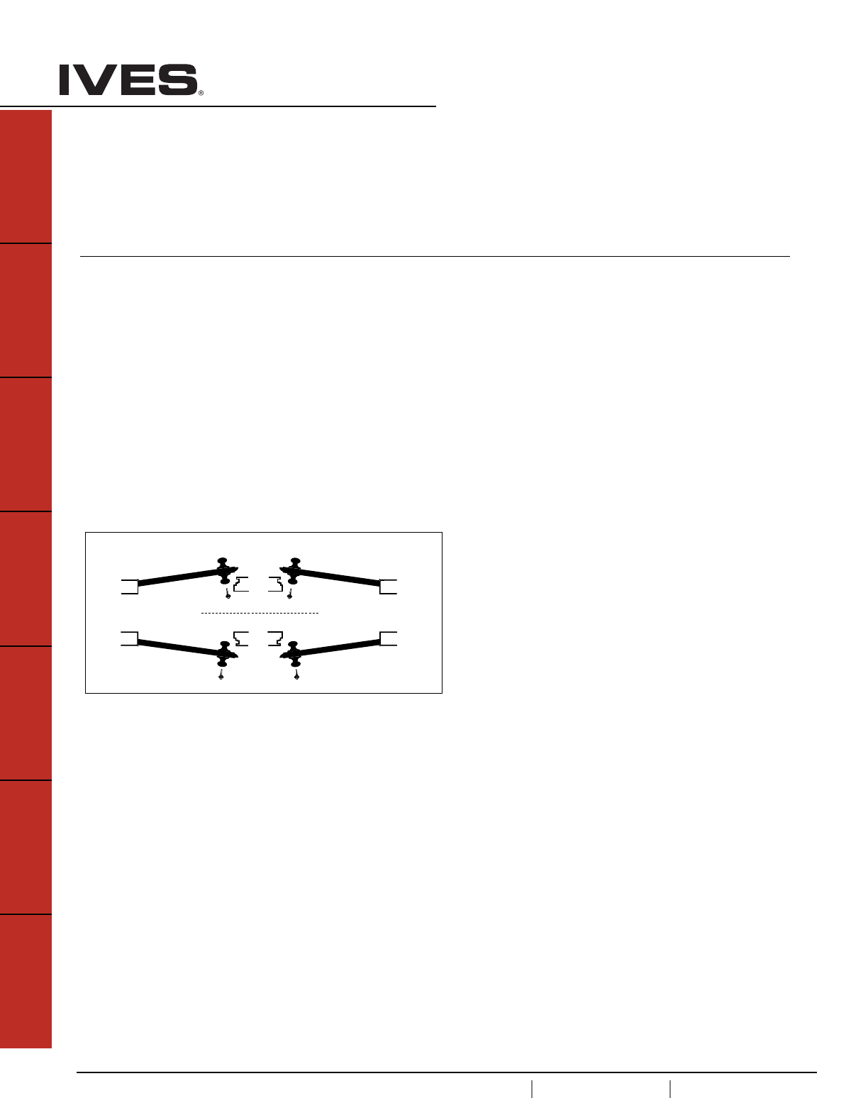
Door Handing
LH INSIDE RH
Left Hand Right Hand
LRB RRB
Left Hand Right Hand
Reverse Bevel OUTSIDE Reverse Bevel
OUTSIDE
INSIDE
A1
USA 1.877.671.7011 Canada 1.905.403.1800 www.ives.ingersollrand.com
Architectural Hinges, Continuous Hinges and Pivots
B
Pulls & Plates
A1
Hinges & Pivots
C
Flush Bolts & Coordinators
D
Latches, Catches & Bolts
E
Stops
F
Exterior Hardware
G
Miscellaneous Hardware
Table Of Contents
Architectural Hinges page
General Hinge Information . . . . . . . . . . . . . . . . . . . . . . . . . . . . . . . . . . . . . A2
How to Order . . . . . . . . . . . . . . . . . . . . . . . . . . . . . . . . . . . . . . . . . . . . . . .A3
ANSI Hinge Identification Reference . . . . . . . . . . . . . . . . . . . . . . . . . . . . . .A4
3PB1 3 Knuckle, Full Mortise . . . . . . . . . . . . . . . . . . . . . . . . . . . .A5
3CB1 3 Knuckle, Full Mortise . . . . . . . . . . . . . . . . . . . . . . . . . . . .A5
3CB1HW 3 Knuckle, Full Mortise . . . . . . . . . . . . . . . . . . . . . . . . . . . . A6
3SP1 3 Knuckle, Full Mortise . . . . . . . . . . . . . . . . . . . . . . . . . . . .A6
5PB1 5 Knuckle, Full Mortise . . . . . . . . . . . . . . . . . . . . . . . . . . . .A7
5BB1 5 Knuckle, Full Mortise . . . . . . . . . . . . . . . . . . . . . . . . . . . .A7
5BB1HW 5 Knuckle, Full Mortise . . . . . . . . . . . . . . . . . . . . . . . . . . . .A8
5BB1WT 5 Knuckle, Full Mortise . . . . . . . . . . . . . . . . . . . . . . . . . . . .A8
5BB4 5 Knuckle, Full Mortise . . . . . . . . . . . . . . . . . . . . . . . . . . . .A9
5BB4HW 5 Knuckle, Full Mortise . . . . . . . . . . . . . . . . . . . . . . . . . . . .A9
5BB1SC 5 Knuckle, Full Mortise . . . . . . . . . . . . . . . . . . . . . . . . . . .A10
5BB1SCHW 5 Knuckle, Full Mortise . . . . . . . . . . . . . . . . . . . . . . . . . . .A10
Electrified Hinge . . . . . . . . . . . . . . . . . . . . . . . . . . . . . . . . . . . . . . . . . . . .A11
Residential Hinges . . . . . . . . . . . . . . . . . . . . . . . . . . . . . . . . . . . . . . . . .A12
Continuous Hinges . . . . . . . . . . . . . . . . . . . . . . . . . . . . . . . . . . . . . . . . .A13
Pivots . . . . . . . . . . . . . . . . . . . . . . . . . . . . . . . . . . . . . . . . . . . . . .A31
A2
USA 1.877.671.7011 Canada 1.905.403.1800 www.ives.ingersollrand.com
Architectural Hinges, Continuous Hinges and Pivots
B
Pulls & Plates
A2
Hinges & Pivots
C
Flush Bolts & Coordinators
D
Latches, Catches & Bolts
E
Stops
F
Exterior Hardware
G
Miscellaneous Hardware
SELECTION OF THE PROPER WEIGHT AND BEARING TYPE
Standard Weight . . . . . Plain Bearing
Standard Weight . . . . . Ball Bearing, Concealed Bearing
Heavy Weight . . . . . . . Ball Bearing, Concealed Bearing
CONSIDERATIONS TO DETERMINE WEIGHT AND BEARING TYPE:
- Weight of Door
- Frequency of use
- Frame
- Door Hardware
Always use ball bearing or concealed bearing hinges for doors with door
closers and in all fire rated openings. Heavy weight doors and high fre-
quency doors should use heavy weight ball bearing or concealed bearing
hinges.
CONSIDERATIONS TO DETERMINE HINGE SIZE
- Door Width
- Door Thickness
- Weight
- Clearance
GUIDELINES FOR HINGE HEIGHT
DOOR THICKNESS DOOR WIDTH HINGE HEIGHT
IN INCHES IN INCHES IN INCHES
1-3/8” Up to 32” 3-1/2
1-3/8 32” to 37” 4”
1-3/4 Up to 36” 4-1/2”
1-3/4 36” to 48” 5”
1-3/4 Over 48” 6”
2” - 2-1/2” Up to 42” 5” heavy weight
2” - 2-1/2” Over 42” 6” heavy weight
General Hinge Information
GUIDELINES FOR HINGE METAL
- Interior door or non-corrosive area use: Plated or painted Steel
- Interior labeled door use: Plated or Painted Steel, Stainless Steel
- Interior door in corrosive area use: Stainless Steel , Brass, Bronze
- Exterior doors use: Stainless Steel, Brass, Bronze
Standard pin material are Brass Hinge – Steel Pin,
Stainless Steel Hinge – Stainless Steel Pin, Steel Hinge – Steel Pin
GUIDELINES FOR FREQUENCY OF DOOR USAGE:
Build Type Daily Usage Hinge Type
High Frequency/ Heavy Weight Door
Large Department Store Entrance 5,000 Heavy Weight
Hospital Corridor and Surgical Doors 5,000 Heavy Weight
Large Office Building Entrance 4,000 Heavy Weight
School Entrance 1,250 Heavy Weight
School Toilet Door 1,250 Heavy Weight
Office Stairwell 500 Heavy Weight
Office Building Toilet Door 400 Heavy Weight
Medium Frequency/ Medium Weight Door
School Corridor Door 100 Standard Weight
Hospital Consultation Rooms 100 Standard Weight
Office Building Corridor Door 80 Standard Weight
Store Toilet Door 60 Standard Weight
Storage Room 50 Standard Weight
Low Frequency /Light Door
Residential Entrance 30 Plain Bearing
Interior Residential 20 Plain Bearing
ANSI/BHMA GRADE/MINIMUM CYCLE REQUIREMENTS
Grade 1: 2,500,000 Heavy Weight Ball & Concealed Bearing
Grade 2: 1,500,000 Standard Weight Ball & Concealed Bearing
Grade 3: 350,000 Light Weight Plain Bearing
CLEARANCE REQUIREMENT*
DOOR THICKNESS CLEARANCE NEEDED HINGE OPEN WIDTH
1-3/8 3/4 4
1-3/4 14
1-3/4 1-1/2 4-1/2
1-3/4 25
1-3/4 36
214-1/2
2 1-1/2 5
2 2-1/2 6
2-1/4 15
2-1/4 26
2-1/2 3/4 5
2-1/2 1-3/4 6
3 3/4 8
3 2-3/4 8
*Distance needed between wall and door at 180º to allow for any projections
from wall; trim, decorative molding, etc.
GUIDELINES FOR NUMBER OF HINGES
- Doors under 7'6" . . . . . . 3 hinges
- Doors over 7'6" . . . . . . . 4 hinges
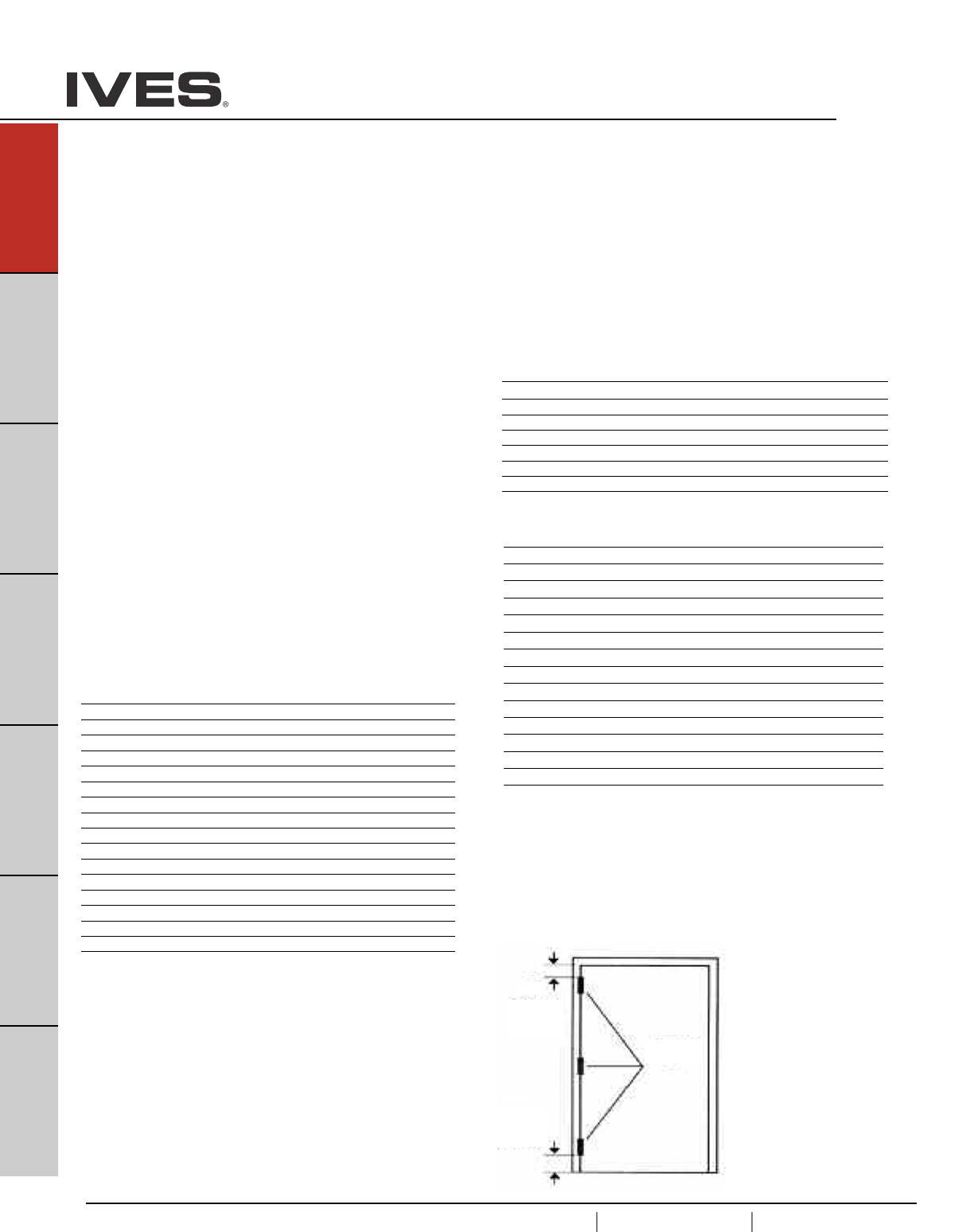
LOCATION OF HINGES
Top hinge 5" from jamb
rabbet to top of barrel
Bottom hinge 10" from
bottom edge of barrel to
finished floor
Third hinge centered
between top and bottom
hinges
Note: Some western states
use a standard 7" from top
and 11" from the bottom
Equal
5"
(127mm)
10"
(254mm)
A3
USA 1.877.671.7011 Canada 1.905.403.1800 www.ives.ingersollrand.com
Architectural Hinges, Continuous Hinges and Pivots
B
Pulls & Plates
A3
Hinges & Pivots
C
Flush Bolts & Coordinators
D
Latches, Catches & Bolts
E
Stops
F
Exterior Hardware
G
Miscellaneous Hardware
How to Order:
Number of Knuckles:
3 - 3 Knuckle
5 - 5 Knuckle
Function:
PB Plain Bearing
BB Ball Bearing
CB Concealed Bearing
SP Spring Hinge
Type:
1Full Mortise
2Half Mortise
3Full Surface
4Half Surface
Weight/Options:
Blank Standard Weight
HW Heavy Weight
SC Swing Clear
SH Security Stud
WT Wide Throw
HT Hospital Tip
RC Round Corners, 1/4" or 5/8" Radius
Size Examples:
3.5 x 3.5
4 x 4
4.5 x 4
4.5 x 4.5
Finish (Some models require extended lead times):
600 USP - Steel
605 US3 - Brass
606 US4 - Brass
612 US10 - Brass
613 US10B - Brass
619 US15 - Brass
625 US26 - Brass
626 US26D - Brass
630 US32D - Stainless
632 US3 - Steel
633 US4 - Steel
639 US10 - Steel
640 US10B - Steel
641 US10A - Steel
643 US11 - Steel
646 US15 - Steel
651 US26 - Steel
652 US26D - Steel
Special Pins Applications:
NRP Non-Removable Pin
TW4 Four Wire
TW8 Eight Wire
MON Monitor
TW4M Four Wire with Monitor
TW8M Eight Wire with Monitor
Ives Hinge Number System
Please note: For availability of specific models, please refer to the item’s catalog page or consult Customer Service.
____ - ____- ____ - ____- ____ - ____- ____
5 BB 1 HW 4.5x4.5 652 NRP
4.5 x 5
4.5 x 6
5 x 4.5
5 x 5
5 x 6
5 x 7 Larger sizes, up to 6 x 8 are available.
Consult factory.

A4
USA 1.877.671.7011 Canada 1.905.403.1800 www.ives.ingersollrand.com
Architectural Hinges
B
Pulls & Plates
A4
Hinges & Pivots
C
Flush Bolts & Coordinators
D
Latches, Catches & Bolts
E
Stops
F
Exterior Hardware
G
Miscellaneous Hardware
ANSI Hinge Identification Reference
A= ANSI
First number indicates material
1 – Cast, forged or extruded brass or bronze
2 – Wrought brass or bronze
5 – Stainless steel
8 – Wrought or forged steel, or malleable iron
Second number indicates product type
1 – Full mortise
2 – Half mortise
3 – Full surface
4 – Half surface
5 – Anchor, pivot reinforced or thrust pivot unit or hinge sets
6 – Olive knuckle hinges
7 – Pivot hinge
8 – Rescue hardware
Third number indicates function
1 – Anti-friction bearing
2 – Anti-friction bearing, swing clear
3 – Plain bearing
4 – 4 to 0, special conditions
Fourth number indicates grade
1 – Grade 1, 4BB Extra Heavy Duty
2 – Grade 2, 2BB Standard Duty
3 – Grade 3, Plain Bearing
Example:
A8111 – Steel, Full Mortise, Anti-friction, Grade 1
A5112 – Stainless, Full Mortise, Anti Friction Bearing, Grade 2
USA 1.877.671.7011 Canada 1.905.403.1800 www.ives.ingersollrand.com
Architectural Hinges
B
Pulls & Plates
A5
Hinges & Pivots
C
Flush Bolts & Coordinators
D
Latches, Catches & Bolts
E
Stops
F
Exterior Hardware
G
Miscellaneous Hardware
A5
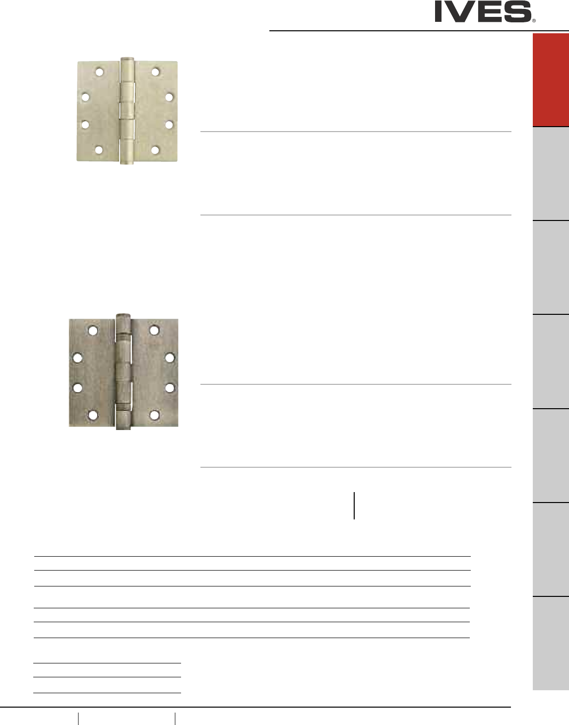
Meets ANSI/BHMA A156.1
A8133 – Steel
A5133 – Stainless Steel
A2133 – Brass
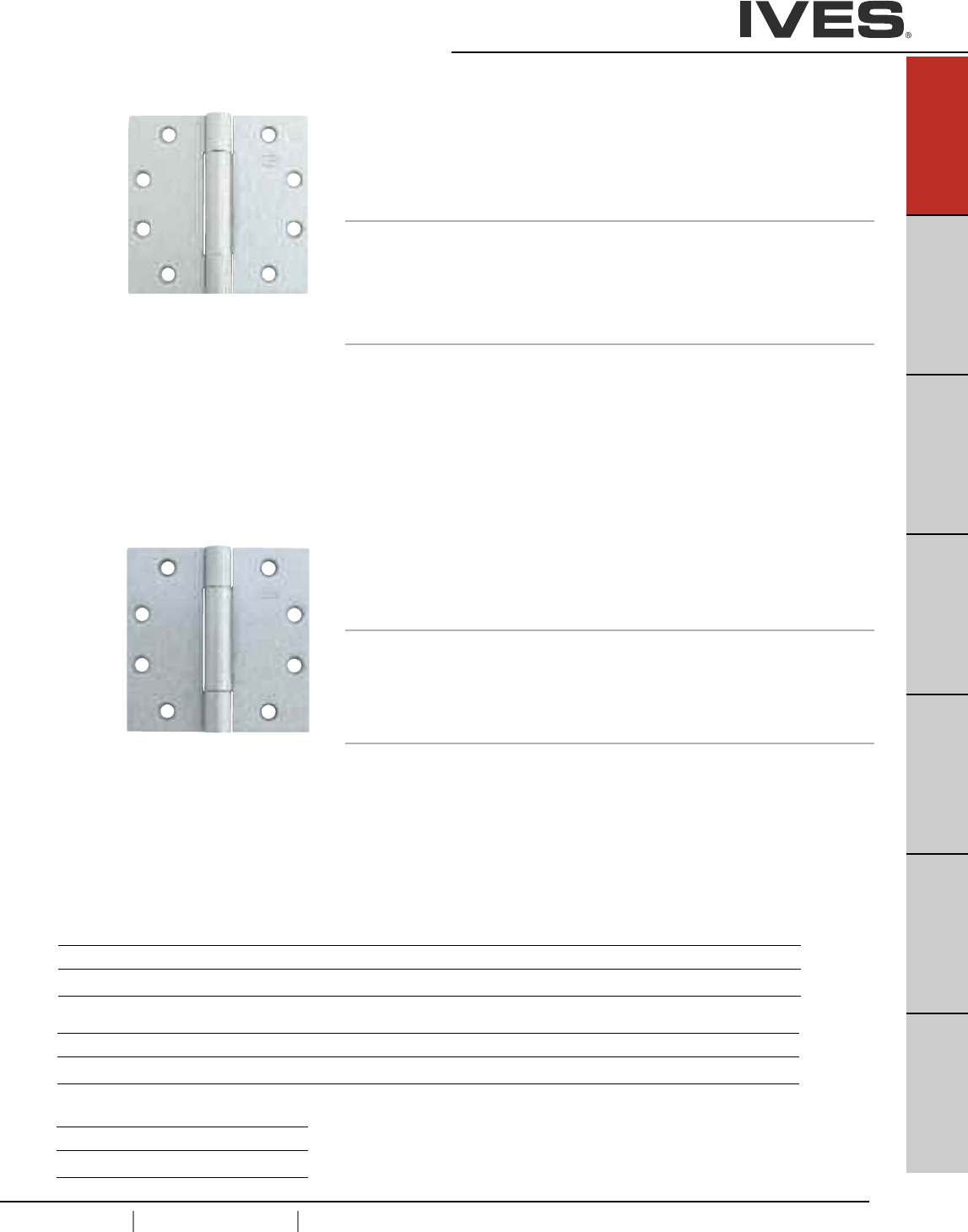
3PB1 3 Knuckle, Plain Bearing Full Mortise Hinge
• For standard weight doors
• Low frequency usage
• Packed with wood and metal screws
Not for use with a door closer.
Options
• NRP, Non-Removable Pin
• SH, Security Stud
• HT, Hospital Tip
• RC, Round Corners - 1/4" or 5/8" Radius
• SEC, Security Fasteners - Pin-in-Socket
Dimensions
Size (Inches) Size (mm) Gauge
3.5 x 3.5 90 x 90 0.134
4 x 4 102 x 102 0.134
4.5 x 4 114 x 102 0.134
4.5 x 4.5 114 x 114 0.134
5 x 4.5 127 x 114 0.134
Meets ANSI/BHMA A156.1
A8112 – Steel
A5112 – Stainless Steel
A2112 – Brass
3CB1 3 Knuckle, Concealed Bearing Full Mortise Hinge
• For standard weight doors
• Medium frequency usage
• Packed with wood and metal screws
Options
• NRP, Non-Removable Pin
• SH, Security stud
• HT, Hospital Tip
• RC, Round Corners - 1/4" or 5/8" Radius
• SEC, Security Fastners - Pin-in-Socket
Dimensions
Size (Inches) Size (mm) Gauge
3.5 x 3.5 90 x 90 0.134
4 x 4 102 x 102 0.134
4.5 x 4 114 x 102 0.134
4.5 x 4.5 114 x 114 0.134
5 x 4.5 127 x 114 0.134
Finishes brass
Ives Finish US3 US4 US10 US10B US10A US11 US15 US26 US26D
BHMA 605 606 612 613 614 616 619 625 626
Finishes steel
Ives Finish USP US3 US4 US10 US10B US10A US11 US15 US26 US26D
BHMA 600 632 633 639 640 641 643 646 651 652
Finishes stainless steel
Ives Finish US32 US32D
BHMA 629 630
A6
USA 1.877.671.7011 Canada 1.905.403.1800 www.ives.ingersollrand.com
Architectural Hinges
B
Pulls & Plates
A6
Hinges & Pivots
C
Flush Bolts & Coordinators
D
Latches, Catches & Bolts
E
Stops
F
Exterior Hardware
G
Miscellaneous Hardware
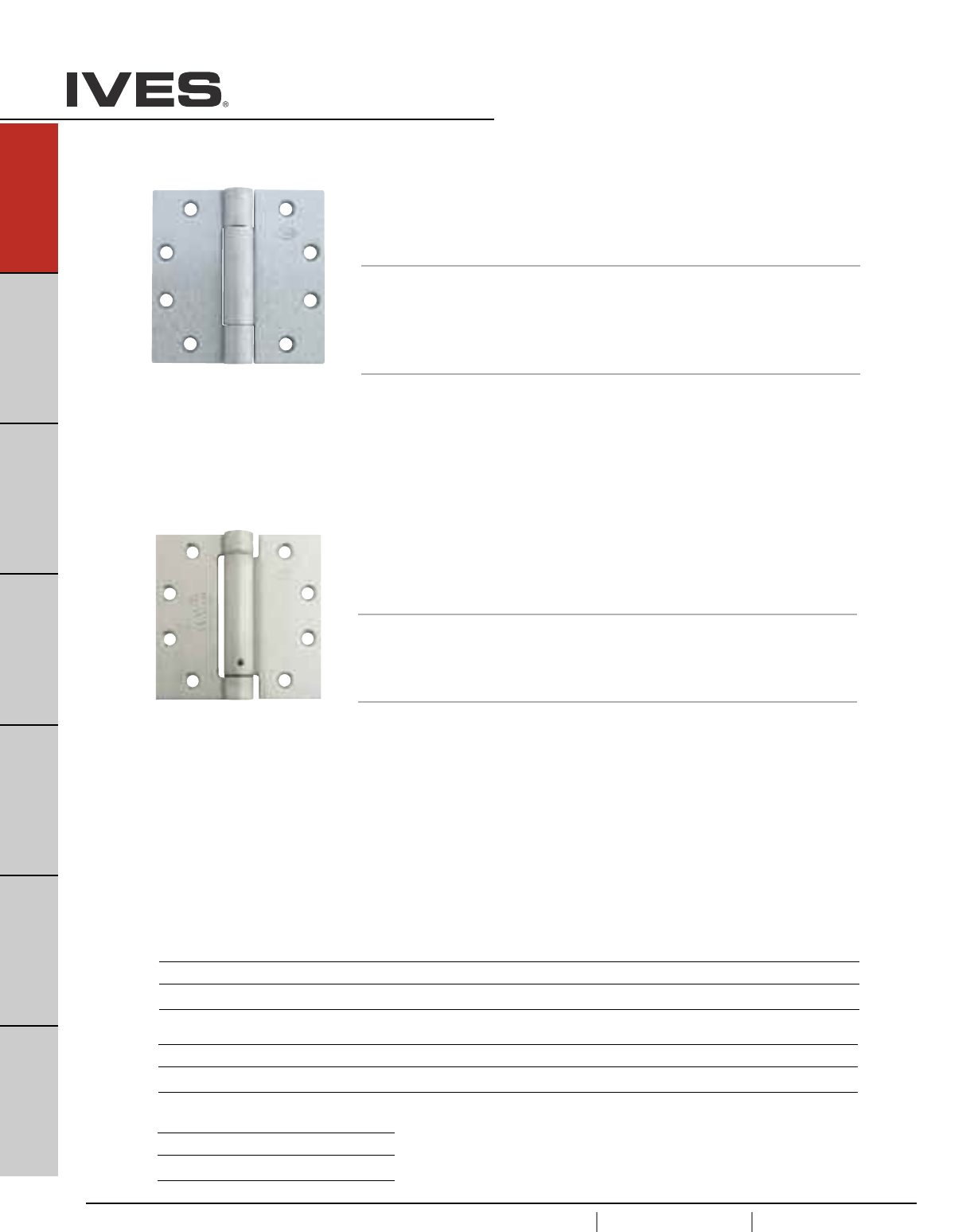
Meets ANSI/BHMA A156.7
K81071F – Steel
K51071F – Stainless Steel
UL listed for use with fire rated doors
3SP1 3 Knuckle Spring Full Mortise Hinge
• For automatic closing of doors
• Packed with wood and metal screws
Options
• HT, Hospital Tip
• RC, Round Corners - 1/4" or 5/8" Radius
• SEC, Security Fastners - Pin-in-Socket
Dimensions
Size (Inches) Size (mm) Gauge
4 x 4 102 x 102 0.134
4.5 x 4 114 x 102 0.134
4.5 x 4.5 114 x 114 0.134
Meets ANSI/BHMA A156.1
A8112 – Steel
A5112 – Stainless Steel
A2112 – Brass
3CB1HW 3 Knuckle, Concealed Bearing Full Mortise Hinge
• For heavy weight doors
• High frequency usage
• Packed with wood and metal screws
Options
• NRP, Non-Removable Pin
• SH, Security stud
• HT, Hospital Tip
• RC, Round Corners - 1/4" or 5/8" Radius
• SEC, Security Fastners - Pin-in-Socket
Dimensions
Size (Inches) Size (mm) Gauge
4.5 x 4 114 x 102 0.180
4.5 x 4.5 114 x 114 0.180
5 x 4.5 127 x 114 0.190
5 x 5 127 x 127 0.190
Finishes brass
Ives Finish US3 US4 US10 US10B US10A US11 US15 US26 US26D
BHMA 605 606 612 613 614 616 619 625 626
Finishes steel
Ives Finish USP US3 US4 US10 US10B US10A US11 US15 US26 US26D
BHMA 600 632 633 639 640 641 643 646 651 652
Finishes stainless steel
Ives Finish US32 US32D
BHMA 629 630
USA 1.877.671.7011 Canada 1.905.403.1800 www.ives.ingersollrand.com
Architectural Hinges
B
Pulls & Plates
A7
Hinges & Pivots
C
Flush Bolts & Coordinators
D
Latches, Catches & Bolts
E
Stops
F
Exterior Hardware
G
Miscellaneous Hardware
A7
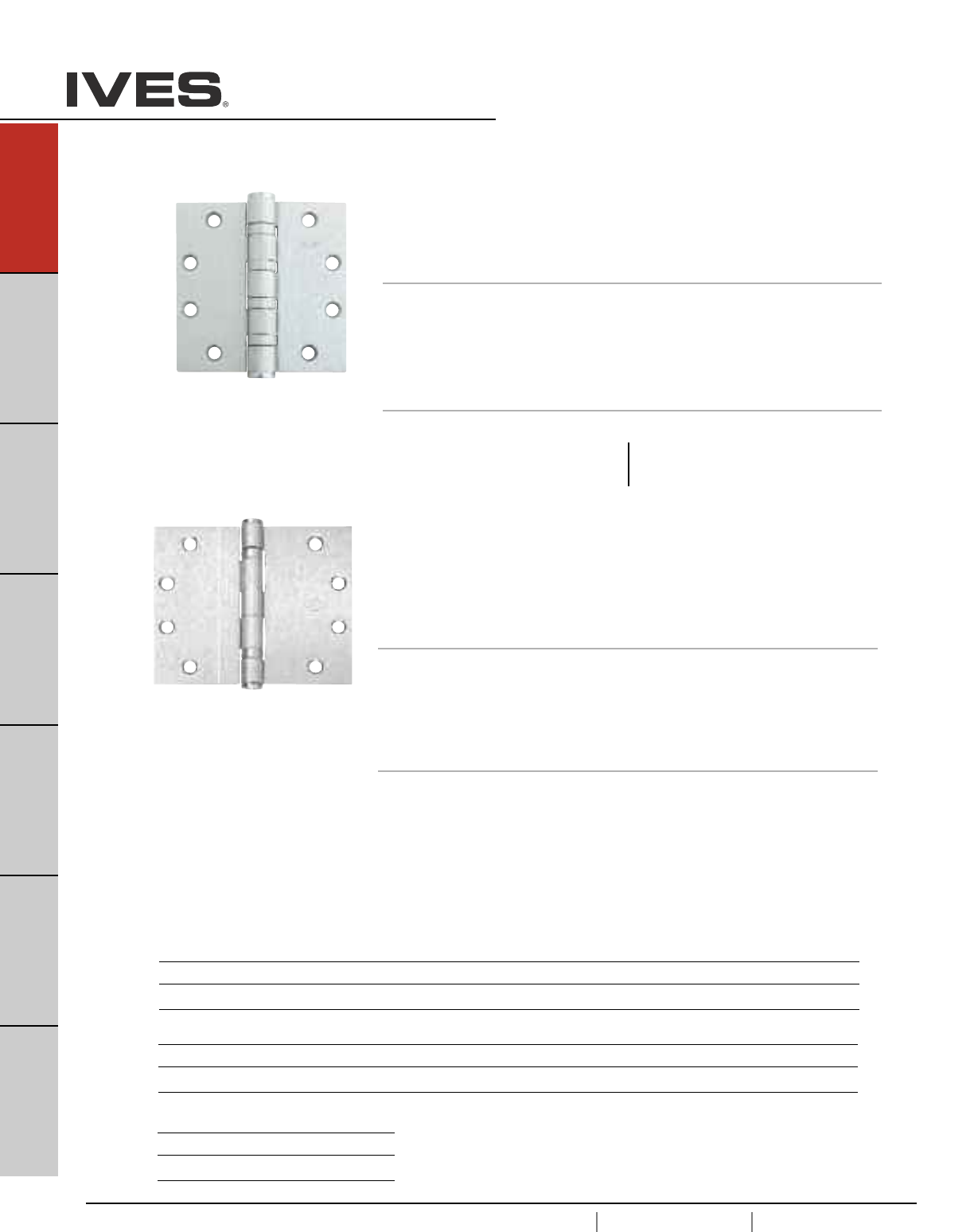
Meets ANSI/BHMA A156.1
A8112 – Steel
A5112 – Stainless Steel
A2112 – Brass
5BB1 5 Knuckle, Ball Bearing Full Mortise Hinge
• For standard weight doors
• Medium frequency usage
• 2 ball bearing
• Packed with wood and metal screws
Options
• NRP, Non-Removable Pin
• SH, Security Stud
• HT, Hospital Tip
• RC, Round Corners - 1/4" or 5/8" Radius
• SEC, Security Fastners - Pin-in-Socket
Dimensions
Size (Inches) Size (mm) Gauge
3.5 x 3.5 80 x 102 0.130
4 x 4 102 x 102 0.130
4.5 x 4 114 x 102 0.134
4.5 x 4.5 114 x 114 0.134
Size (Inches) Size (mm) Gauge
5 x 4.5 127 x 114 0.146
5 x 5 127 x 127 0.146
Meets ANSI/BHMA A156.1
A8133 – Steel
A5133 – Stainless Steel
A2133 – Brass
5PB1 5 Knuckle, Plain Bearing Full Mortise Hinge
• For standard weight doors
• Low frequency usage
• Packed with wood and metal screws
Not for use with a door closer.
Options
• NRP, Non-Removable Pin
• SH, Security Stud
• HT, Hospital Tip
• RC, Round Corners - 1/4" or 5/8" Radius
• SEC, Security Fastners - Pin-in-Socket
Dimensions
Size (Inches) Size (mm) Gauge
3.5 x 3.5 89 x 89 0.123
4 x 4 102 x 102 0.134
4.5 x 4 114 x 102 0.134
4.5 x 4.5 114 x 114 0.134
5 x 4.5 127 x 114 0.134
Finishes brass
Ives Finish US3 US4 US10 US10B US10A US11 US15 US26 US26D
BHMA 605 606 612 613 614 616 619 625 626
Finishes steel
Ives Finish USP US3 US4 US10 US10B US10A US11 US15 US26 US26D
BHMA 600 632 633 639 640 641 643 646 651 652
Finishes stainless steel
Ives Finish US32 US32D
BHMA 629 630
A8
USA 1.877.671.7011 Canada 1.905.403.1800 www.ives.ingersollrand.com
Architectural Hinges
B
Pulls & Plates
A8
Hinges & Pivots
C
Flush Bolts & Coordinators
D
Latches, Catches & Bolts
E
Stops
F
Exterior Hardware
G
Miscellaneous Hardware
Meets ANSI/BHMA A156.1
A8111 – Steel
5BB1WT 5 Knuckle, Ball Bearing, Wide Throw
Full Mortise Hinge
• For medium weight doors
• Medium frequency usage
• 2 ball bearing
• Packed with wood and metal screws
Options
• NRP, Non-Removable Pin
• SH, Security Stud
• HT, Hospital Tip
• RC, Round Corners - 1/4" or 5/8" Radius
• SEC, Security Fastners - Pin-in-Socket
Dimensions
Size (Inches) Size (mm) Gauge
4.5 x 5 114 x 127 0.134
4.5 x 6 114 x 152 0.134
5 x 6 127 x 152 0.146
5 x 7 127 x 178 0.146
5 x 8 127 x 203 0.146
Meets ANSI/BHMA A156.1
A8111 – Steel
A5111 – Stainless Steel
A2111 – Brass
5BB1HW 5 Knuckle, Ball Bearing, Heavy Weight
Full Mortise Hinge
• For heavy weight doors
• High frequency usage
• 4 ball bearing
• Packed with wood and metal screws
Options
• NRP, Non-Removable Pin
• SH, Security Stud
• HT, Hospital Tip
• RC, Round Corners - 1/4" or 5/8" Radius
• SEC, Security Fastners - Pin-in-Socket
Dimensions
Size (Inches) Size (mm) Gauge
4.5 x 4 114 x 102 0.180
4.5 x 4.5 114 x 114 0.180
Size (Inches) Size (mm) Gauge
5 x 4.5 127 x 114 0.190
5 x 5 127 x 127 0.190
Finishes brass
Ives Finish US3 US4 US10 US10B US10A US11 US15 US26 US26D
BHMA 605 606 612 613 614 616 619 625 626
Finishes steel
Ives Finish USP US3 US4 US10 US10B US10A US11 US15 US26 US26D
BHMA 600 632 633 639 640 641 643 646 651 652
Finishes stainless steel
Ives Finish US32 US32D
BHMA 629 630
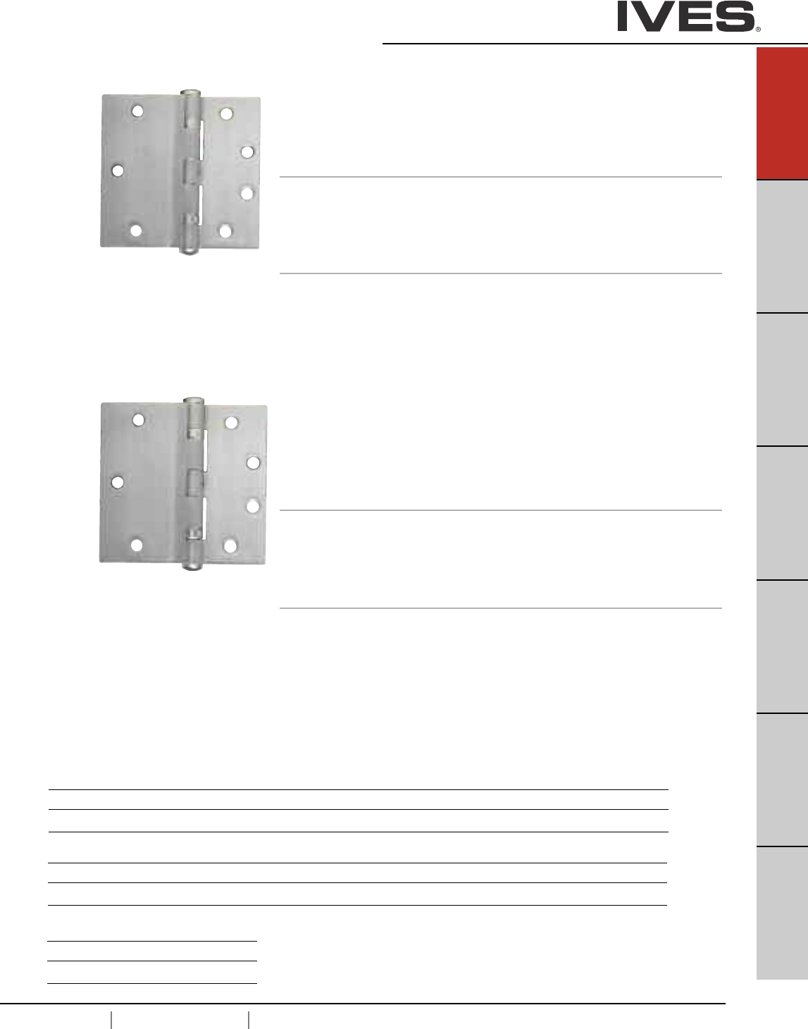
USA 1.877.671.7011 Canada 1.905.403.1800 www.ives.ingersollrand.com
Architectural Hinges
B
Pulls & Plates
A9
Hinges & Pivots
C
Flush Bolts & Coordinators
D
Latches, Catches & Bolts
E
Stops
F
Exterior Hardware
G
Miscellaneous Hardware
A9
Meets ANSI/BHMA A156.1
A8412 – Steel
5BB4 5 Knuckle, Ball Bearing, Half Surface Hinge
• For standard weight doors
• Medium frequency usage
• 2 ball bearing
• Packed with through bolts, grommets and sheet metal screws
Options
• NRP, Non-Removable Pin
• HT, Hospital Tip
• RC, Round Corners - 1/4" or 5/8" Radius
• SEC, Security Fastners - Pin-in-Socket
Dimensions
Size (Inches) Size (mm) Gauge
4.5 114 0.134
Meets ANSI/BHMA A156.1
A8411 – Steel
5BB4HW 5 Knuckle, Ball Bearing, Half Surface
Heavy Weight Hinge
• For heavy weight doors
• High frequency usage
• 4 ball bearing
• Packed with through bolts, grommets and sheet metal screws
Options
• NRP, Non-Removable Pin
• HT, Hospital Tip
• RC, Round Corners - 1/4" or 5/8" Radius
• SEC, Security Fastners - Pin-in-Socket
Dimensions
Size (Inches) Size (mm) Gauge
4.5 114 0.180
Finishes brass
Ives Finish US3 US4 US10 US10B US10A US11 US15 US26 US26D
BHMA 605 606 612 613 614 616 619 625 626
Finishes steel
Ives Finish USP US3 US4 US10 US10B US10A US11 US15 US26 US26D
BHMA 600 632 633 639 640 641 643 646 651 652
Finishes stainless steel
Ives Finish US32 US32D
BHMA 629 630
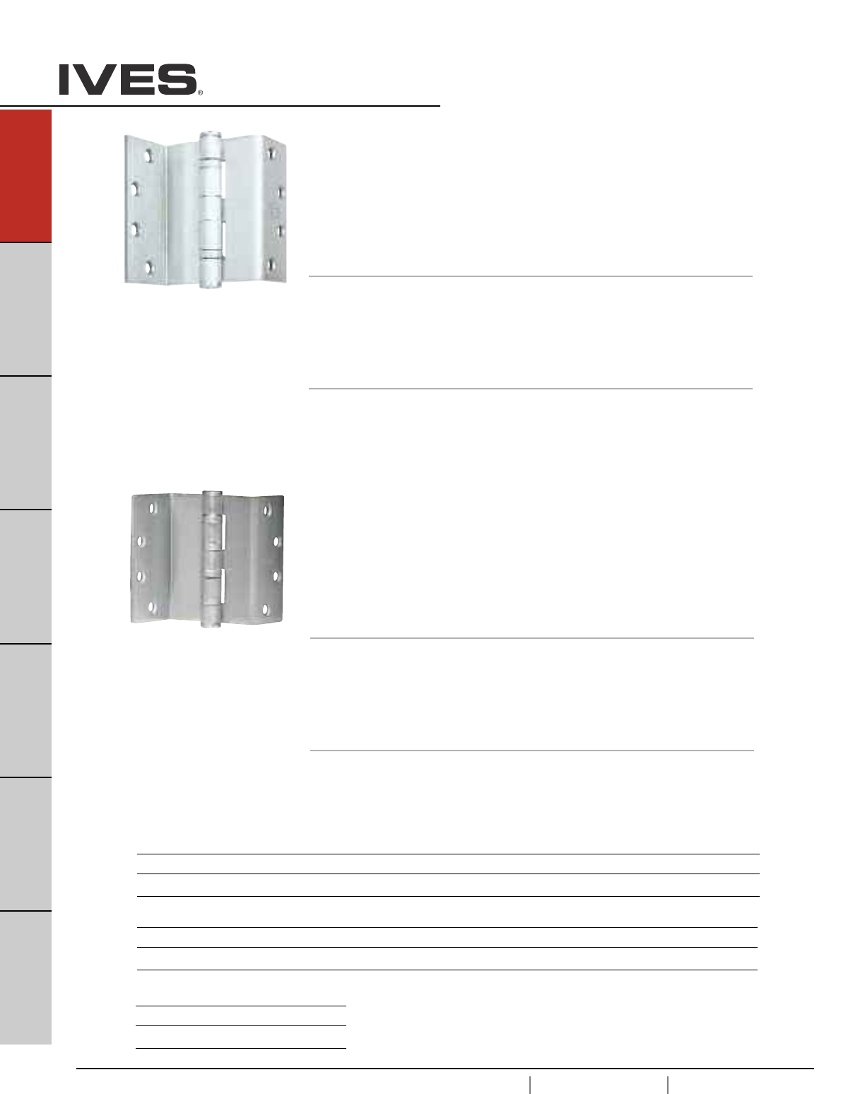
A10
USA 1.877.671.7011 Canada 1.905.403.1800 www.ives.ingersollrand.com
Architectural Hinges
B
Pulls & Plates
A10
Hinges & Pivots
C
Flush Bolts & Coordinators
D
Latches, Catches & Bolts
E
Stops
F
Exterior Hardware
G
Miscellaneous Hardware
Meets ANSI/BHMA A156.1
A8121 – Steel
5BB1SCHW 5 Knuckle, Ball Bearing, Swing Clear
Heavy Weight Full Mortise Hinge
• For heavy weight doors
• Beveled edge standard
• High frequency usage
• 2 ball bearing
• Packed with flat head wood and metal screws
Designed to completely clear the opening when door is opened 92 degrees.
Options
• NRP, Non-Removable Pin
• B, beveled edge door
• HT, Hospital Tip
• RC, Round Corners - 1/4" or 5/8" Radius
• SEC, Security Fastners - Pin-in-Socket
Dimensions
Size (Inches) Size (mm) Gauge
4.5 114 0.180
5 127 0.190
Meets ANSI/BHMA A156.1
A8122 – Steel
A5122 – Stainless Steel
A2122 – Brass
5BB1SC 5 Knuckle, Ball Bearing, Swing Clear
Full Mortise Hinge
• For standard weight doors
• Square edge standard
• Medium frequency usage
• 2 ball bearing
• Packed with flat head wood and metal screws
Designed to completely clear the opening when door is opened 92 degrees.
Options
• NRP, Non-Removable Pin
• B, beveled edge door
• HT, Hospital Tip
• RC, Round Corners - 1/4" or 5/8" Radius
• SEC, Security Fastners - Pin-in-Socket
Dimensions
Size (Inches) Size (mm) Gauge
4.5 114 0.134
5 127 0.134
Finishes brass
Ives Finish US3 US4 US10 US10B US10A US11 US15 US26 US26D
BHMA 605 606 612 613 614 616 619 625 626
Finishes steel
Ives Finish USP US3 US4 US10 US10B US10A US11 US15 US26 US26D
BHMA 600 632 633 639 640 641 643 646 651 652
Finishes stainless steel
Ives Finish US32 US32D
BHMA 629 630
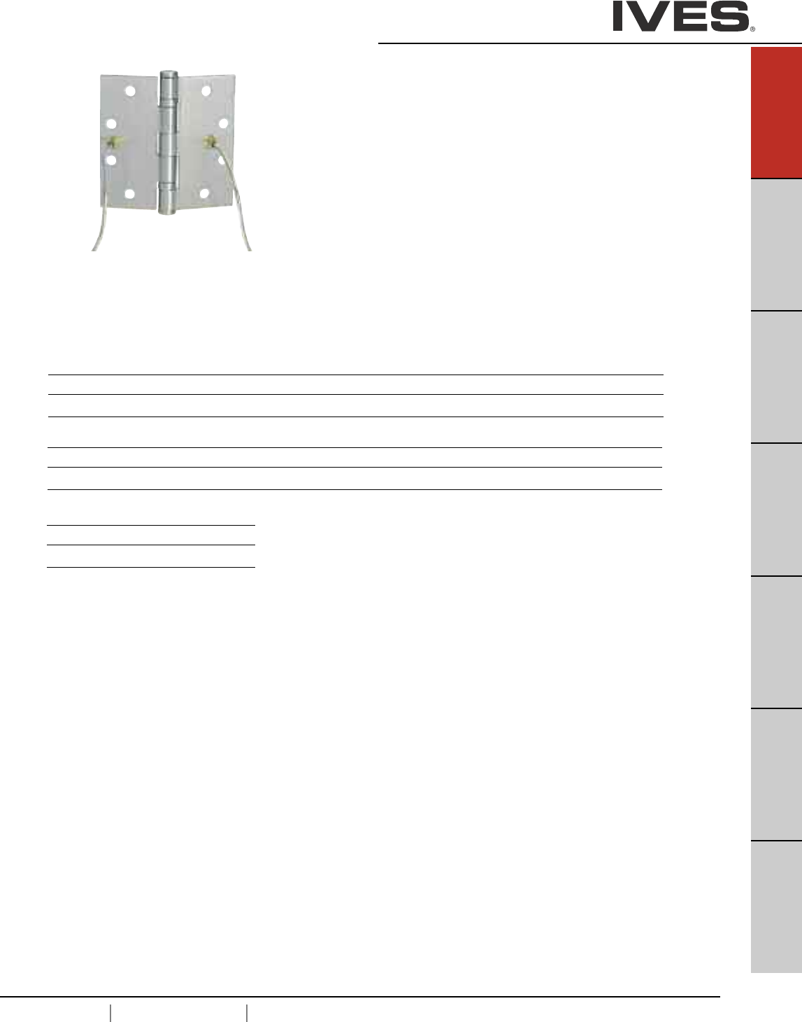
USA 1.877.671.7011 Canada 1.905.403.1800 www.ives.ingersollrand.com
Architectural Hinges
B
Pulls & Plates
A11
Hinges & Pivots
C
Flush Bolts & Coordinators
D
Latches, Catches & Bolts
E
Stops
F
Exterior Hardware
G
Miscellaneous Hardware
A11
UL Listed - UL634
Meets ANSI/BHMA A156.1
A8111 – Steel
A5111 – Stainless Steel
A2111 – Brass
Electrified Hinge
Available Options
- Through Wire - TW4 (4 wires) & TW8 (8 wires)
- Monitor – MON
- Through Wire with Monitor – TW4M & TW8M
• Available in 3 and 5 Knuckle
• One hinge per box, packed with wood and machine screws
• Hinge is NRP as a standard
• High quality brass ferrules and plastic tubing protect the wires
• Through-wire hinges cycle tested to ensure durability
• Ives warranty applies - 12 months from date of shipment
Through-Wire is rated for 50 volts AC/DC at 3.5 amp continuous and 16 amp pulse,
maximum pulse 400 mili second.
Monitor rated 30VDC at .5 amp
Finishes brass
Ives Finish US3 US4 US10 US10B US10A US11 US15 US26 US26D
BHMA 605 606 612 613 614 616 619 625 626
Finishes steel
Ives Finish USP US3 US4 US10 US10B US10A US11 US15 US26 US26D
BHMA 600 632 633 639 640 641 643 646 651 652
Finishes stainless steel
Ives Finish US32 US32D
BHMA 629 630
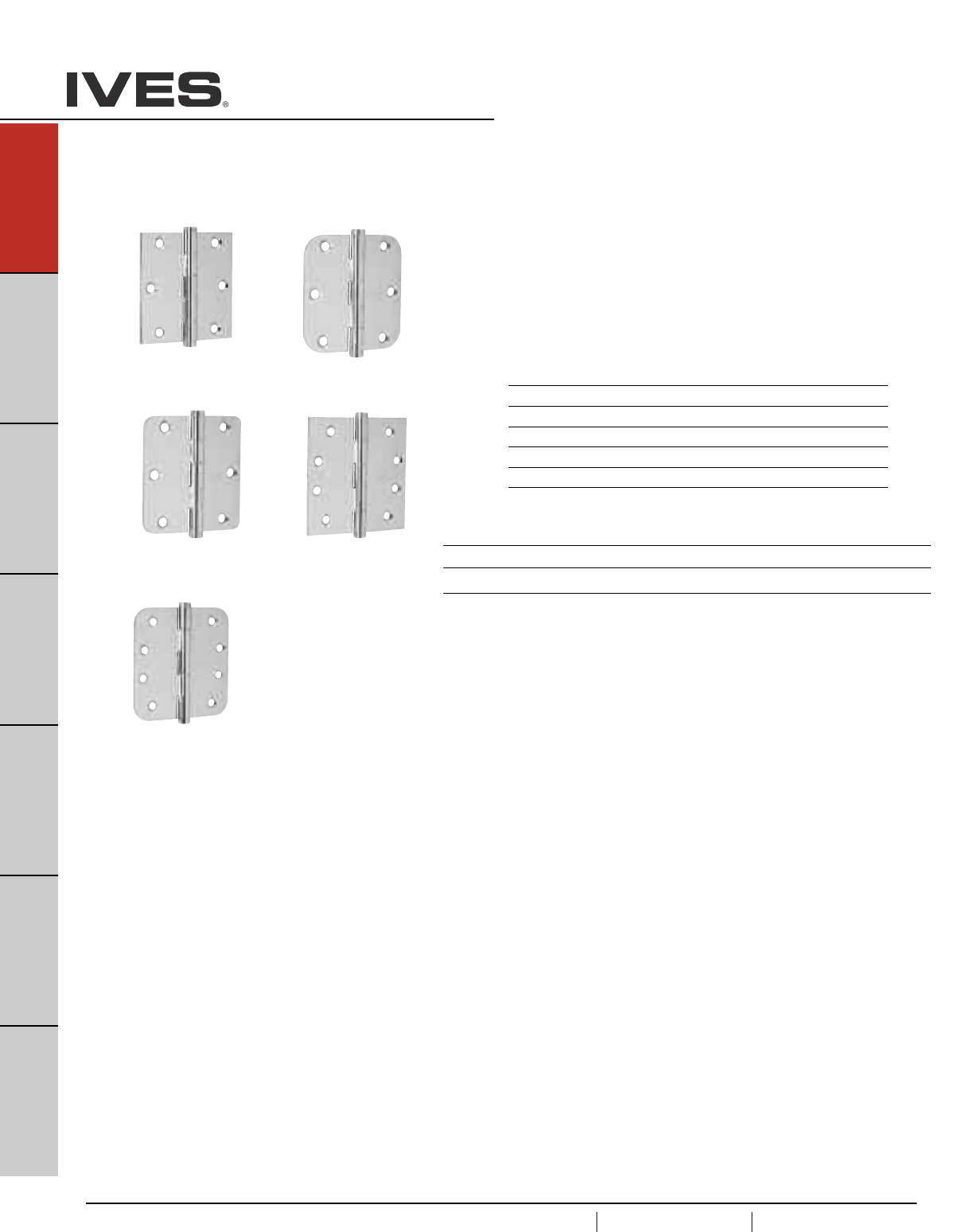
A12
USA 1.877.671.7011 Canada 1.905.403.1800 www.ives.ingersollrand.com
Architectural Hinges
B
Pulls & Plates
A12
Hinges & Pivots
C
Flush Bolts & Coordinators
D
Latches, Catches & Bolts
E
Stops
F
Exterior Hardware
G
Miscellaneous Hardware
1000 Series Residential Hinges
• Full mortise hinges in 2 sizes: 3-1/2" and 4".
• Two corner options: Square corners and 5/8" or 1/4"
radius corners.
• Substrates include: Steel.
Model Size Corner
1010 3-1/2" x 3-1/2" Square Corner
1011 3-1/2" x 3-1/2" 5/8" Radius Corner
1012 3-1/2" x 3-1/2" 1/4" Radius Corner
1020 4" x 4" Square Corner
1021 4" x 4" 5/8" Radius Corner
1010
Schlage Carded Only
1011
1012
Schlage Carded Only
1021
Schlage Carded Only
1020
Schlage Carded Only
Finishes steel
Ives Finish F605E F609E F619E F620E* F625E** F716E
BHMA 632 646 651
* not available on 1012 hinge
* only available on 1011
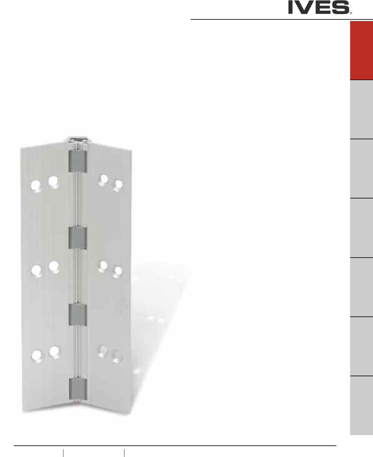
USA 1.877.671.7011 Canada 1.905.403.1800 www.ives.ingersollrand.com
Continuous Hinges
Ives Continuous Hinges are designed to last the life of the building.
The unique design distributes the weight of the door along the entire
length of the frame, reducing the high amount of stress normally
associated at top of door and frame on butt hinge applications. Not
only does this reduce hinge failure, it also keeps your door in constant
alignment, eliminating the chance of door sag. These characteristics
make continuous hinges suitable for high use/high traffic doors.
The design of a continuous hinge eliminates the gap between the
door and the frame. The absence of gap also helps prevents finger
from being pinched, making it a safer device than traditional hinges.
These benefits result in higher efficiency and less maintenance,
maximizing the value of your opening investment.
Continuous hinges are available in two styles; aluminum geared
and pin and barrel in steel or stainless steel.
B
Pulls & Plates
A13
Hinges & Pivots
C
Flush Bolts & Coordinators
D
Latches, Catches & Bolts
E
Stops
F
Exterior Hardware
G
Miscellaneous Hardware
A13
Continuous Hinge Table Of Contents
page
Continuous Hinge Types . . . . . . . . . . . . . . . . . . . . . . . . . . . . . . . . . . . . .A14
Cross Reference Guide . . . . . . . . . . . . . . . . . . . . . . . . . . . . . . . . . . . . . .A15
Aluminum Geared Hinges
General Information . . . . . . . . . . . . . . . . . . . . . . . . . . . . . . . . . . . . . . . .A16
Electrified Options . . . . . . . . . . . . . . . . . . . . . . . . . . . . . . . . . . . . . . . . .A16
How to Order . . . . . . . . . . . . . . . . . . . . . . . . . . . . . . . . . . . . . . . . . . . . .A17
Door Sizing . . . . . . . . . . . . . . . . . . . . . . . . . . . . . . . . . . . . . . . . . . . . . . .A18
045HD . . . . . . . . . . . . . . .Half Surface . . . . . . . . . . . . . . . . . . . . . . . . .A19
046HD . . . . . . . . . . . . . . .Half Surface . . . . . . . . . . . . . . . . . . . . . . . . .A19
053HD . . . . . . . . . . . . . . .Half Surface . . . . . . . . . . . . . . . . . . . . . . . . .A20
054HD . . . . . . . . . . . . . . .Half Surface . . . . . . . . . . . . . . . . . . . . . . . . .A20
112HD . . . . . . . . . . . . . . .Full Mortise . . . . . . . . . . . . . . . . . . . . . . . . .A21
157HD . . . . . . . . . . . . . . .Full Surface, Center Pivot . . . . . . . . . . . . . . .A21
210HD . . . . . . . . . . . . . . .Full Surface, Swing Clear . . . . . . . . . . . . . . .A22
224HD . . . . . . . . . . . . . . .Full Mortise, Edge Protector . . . . . . . . . . . . .A22
Electrical Cutouts . . . . . . . . . . . . . . . . . . . . . . . . . . . . . . . . . . . . . . . . . .A23
Pin and Barrel Hinges
General Information . . . . . . . . . . . . . . . . . . . . . . . . . . . . . . . . . . . . . . . .A24
Electrified Options . . . . . . . . . . . . . . . . . . . . . . . . . . . . . . . . . . . . . . . . .A24
How to Order . . . . . . . . . . . . . . . . . . . . . . . . . . . . . . . . . . . . . . . . . . . . .A25
Door Sizing . . . . . . . . . . . . . . . . . . . . . . . . . . . . . . . . . . . . . . . . . . . . . . .A26
600, 700 . . . . . . . . . . . . . .Full Mortise . . . . . . . . . . . . . . . . . . . . . . . . .A27
602, 702 . . . . . . . . . . . . . .Full Surface . . . . . . . . . . . . . . . . . . . . . . . . .A27
611, 711 . . . . . . . . . . . . . .Swing Clear . . . . . . . . . . . . . . . . . . . . . . . . . .A28
705 . . . . . . . . . . . . . . . . . .Full Mortise, Full Wrap . . . . . . . . . . . . . . . . .A28
715 . . . . . . . . . . . . . . . . . .Full Mortise, Full Wrap . . . . . . . . . . . . . . . . .A29
Electrical Cutouts . . . . . . . . . . . . . . . . . . . . . . . . . . . . . . . . . . . . . . . . . .A30
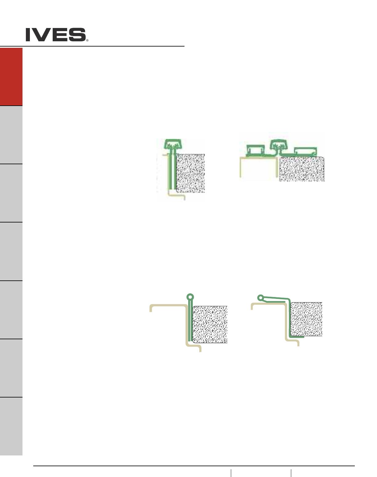
A14
USA 1.877.671.7011 Canada 1.905.403.1800 www.ives.ingersollrand.com
Continuous Hinges
B
Pulls & Plates
A14
Hinges & Pivots
C
Flush Bolts & Coordinators
D
Latches, Catches & Bolts
E
Stops
F
Exterior Hardware
G
Miscellaneous Hardware
Aluminum Geared
Geared continuous hinges utilize a single gear section for the leaf and
a separate gear section for the frame side of the door. The two are
held in place together by a full length cover channel and rotate on a
series of bearings.
Pin and Barrel
Pin and Barrel hinges share many of the same characteristics of a
traditional hinge. Both have a center pin and rolled knuckles. However,
a continuous Pin and Barrel hinge stretches along the entire length of
the frame. IVES offers both stainless steel and primed steel to best
match your specific application.
0.060"
[
Lifetime Warranty Ives continuous hinges carry a limited lifetime war-
ranty, ensuring your opening will function to your satisfaction every time.
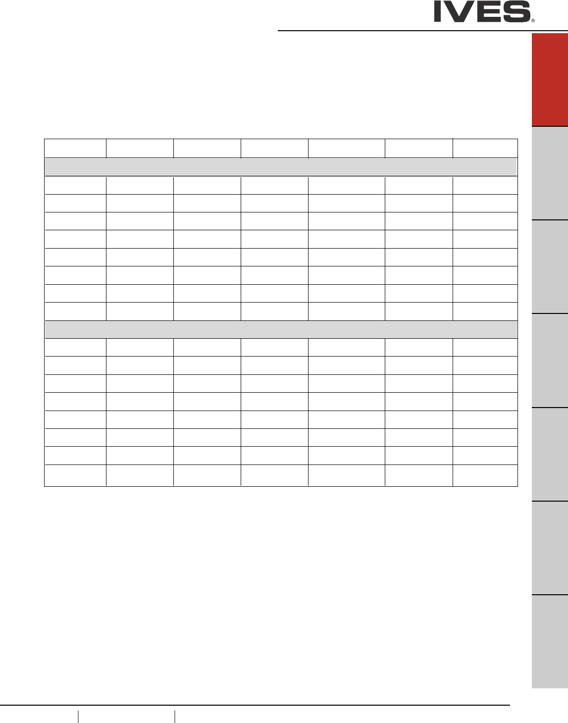
USA 1.877.671.7011 Canada 1.905.403.1800 www.ives.ingersollrand.com
Continuous Hinges
B
Pulls & Plates
A15
Hinges & Pivots
C
Flush Bolts & Coordinators
D
Latches, Catches & Bolts
E
Stops
F
Exterior Hardware
G
Miscellaneous Hardware
A15
Ives Hager Markar McKinney Pemko Select Stanley
Geared
045HD 780-045HD
046HD 780-046HD
053HD 780-053HD
054HD 780-054HD
112HD 780-112HD MCK-12HD FMSLFHD SL11HD 661HD
210HD 780-210HD MCK-22HD FSHD SL21HD 665HD
224HD 780-224HD MCK-25HD FMHD SL24HD 662HD
157HD 780-157HD MCK-58HD FSCPHD SL57HD 664HD
Pin and Barrel
600 FM200 SL200
602 FS202
611 N/A
700 790-900 FM300 SL300 651
702 FS302 SL302
705 790-905 HG305 SL305 652
711 790-911 HG311 SL311 656
715 790-915 HG315 653
Cross Reference Guide

A16
USA 1.877.671.7011 Canada 1.905.403.1800 www.ives.ingersollrand.com
Continuous Hinges
B
Pulls & Plates
A16
Hinges & Pivots
C
Flush Bolts & Coordinators
D
Latches, Catches & Bolts
E
Stops
F
Exterior Hardware
G
Miscellaneous Hardware
General Information
Material
6063-T6 Aluminum
Standard Lengths
83", 85", 95", 120"
Custom lengths are available up to 120", consult factory.
Finishes
CL - US28 (628) Clear Anodized
BR - 313AN (710) Dark Bronze
Hinge Duty
All Ives Aluminum Geared Hinges are Heavy Duty (HD).
Amount of bearings varies by size:
83" – 32 Bearings
85" – 32 Bearings
95" – 36 Bearings
120"- 47 Bearings
Door Weight
Each hinge can hold a door up to 450 lbs (Rivet nuts recommended)
and a max door width of 4'0".
ANSI Certified
All Ives Aluminum Geared Hinges are certified to ANSI 156.26, Grade 1
UL Listed
All Ives Aluminum Geared Hinges are tested and approved UL 10C (90 minutes).
Field Modifications:
All Ives Aluminum Geared Continuous Hinges can be cut to length during installation. The unique
mounting pattern allows to cut up to 6" from bottom while still having double row fasteners. If cut more
than 13.5", other modifications may be necessary.
Electrification Options
Only available for the full mortise hinges
Electric Power Transfer (EPT)
Electric power transfer provides a means of transferring power from the door frame to the edge of a
swinging door. Ives Continuous Hinges provide standard cut outs to fit Von Duprin EPT-2, EPT-10 and
PNT-1 devices. Consult factory for other electrical cut out options.
Electrical Through-Wire (TW)
Provides electric power transfer from the frame to the door in order to supply power to an electrified
mortise or cylindrical locks, exit devices with electric latch retraction, and/or electric strikes (pairs of
doors). Through-wire is rated 50 volts AC/DC at 3.5 amp continuous and 16 amp pulse. Maximum pulse
400 milliseconds. Ives thru-wire hinges are fully compatible with 4 wire and 8 wire installations.
Aluminum Geared Hinges
USA 1.877.671.7011 Canada 1.905.403.1800 www.ives.ingersollrand.com
Continuous Hinges
B
Pulls & Plates
A17
Hinges & Pivots
C
Flush Bolts & Coordinators
D
Latches, Catches & Bolts
E
Stops
F
Exterior Hardware
G
Miscellaneous Hardware
A17
How to Order:
Model
045HD Half Surface
046HD Half Surface
053HD Half Surface
054HD Half Surface
112HD Full Mortise
157HD Full Surface - Center Pivot
210HD Full Surface - Swing Clear
224HD Full Mortise - Edge Protector
Finish
CL Clear
BR Bronze
Length
83"
85"
95"
120"
Options
*EPT Electric Power Transfer Prep
*TW8 Electric Through Wire
SEC Security Fasteners - Pin-in-Socket
WD Wood Fasteners
HM Thread forming screws (pilot hole required)
* Full Mortise Models Only
____ - ____ - __ - ____
112HD CL 83 EPT
Aluminum Geared Hinges
Other lengths available up to 120", consult factory. Handing required.
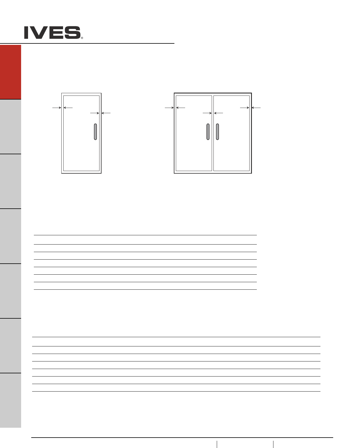
A18
USA 1.877.671.7011 Canada 1.905.403.1800 www.ives.ingersollrand.com
Continuous Hinges
B
Pulls & Plates
A18
Hinges & Pivots
C
Flush Bolts & Coordinators
D
Latches, Catches & Bolts
E
Stops
F
Exterior Hardware
G
Miscellaneous Hardware
SINGLE DOOR
Door Under-Sizing
Hinge-Side Lock-Side Frame Beveled Door Square Beveled
Model Clearance Clearance Irregularity Clearance Edged Edged
045HD 5/32" 1/8" 1/32" 1/32" 5/16" 11/32"
046HD 5/32" 1/8" 1/32" 1/32" 5/16" 11/32"
053HD 5/32" 1/8" 1/32" 1/32" 5/16" 11/32"
054HD 5/32" 1/8" 1/32" 1/32" 5/16" 11/32"
112HD 5/16" 1/8" 1/32" 1/32" 15/32" 1/2"
224HD 5/16" 1/8" 1/32" 1/32" 15/32" 1/2"
210HD 1/16" 1/8" 1/32" 1/32" 7/32" 1/4"
157HD 1/16" 1/8" 1/32" 1/32" 7/32" 1/4"
PAIR OF DOORS
Door Under-Sizing
Square Square Beveled Beveled
Hinge-Side Lock-Side Frame Beveled Door Edged Edged Edged Edged
Model Clearance Clearance Irregularity Clearance Total Each Door Total Each Door
045HD 5/32" 3/16" 1/16" 1/16" 9/16" 9/32" 5/8" 5/16"
046HD 5/32" 3/16" 1/16" 1/16" 9/16" 9/32" 5/8" 5/16"
053HD 5/32" 3/16" 1/16" 1/16" 9/16" 9/32" 5/8" 5/16"
054HD 5/32" 3/16" 1/16" 1/16" 9/16" 9/32" 5/8" 5/16"
112HD 5/16" 3/16" 1/16" 1/16" 7/8" 7/16" 15/16" 15/32"
224HD 5/16" 3/16" 1/16" 1/16" 7/8" 7/16" 15/16" 15/32"
210HD 1/16" 3/16" 1/16" 1/16" 3/8" 3/16" 7/16" 7/32"
157HD 1/16" 3/16" 1/16" 1/16" 3/8" 3/16" 7/16" 7/32"
Hinge
Side
Clearance
1/32”
Frame
Irregularity
1/8” Hinge
Side
Clearance
Hinge
Side
Clearance
1/16”
Frame
Irregularity
3/16”
Aluminum Geared Hinges - Clearance Requirements
Templates and installation instructions available on line at ives.ingersollrand.com
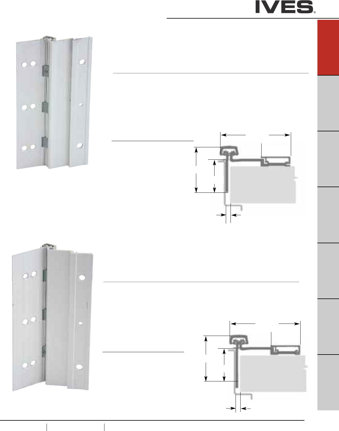
045HD Half Surface Continuous Hinge
• Half surface for retrofit or new construction
• Non-handed
• Frame leaf depth 1-9/16"
• 9/32" door inset
Standard lengths 83", 85", 95", 120"
Standard Mounting Hardware
12-24 x 1/2" steel self tapping screw
1/4-20 x 1-1/2" AL Sex Bolt
1/4-20 x 1" Steel Shoulder Bolt
12-24 x 3/4" Steel Self Drilling Shoulder Bolt
Optional SEC-Security Fasteners available
046HD Half Surface Continuous Hinge
• Half surface for retrofit or new construction
• Non-handed
• Frame leaf depth 1-15/16"
• 9/32" door inset
Standard lengths 83", 85", 95", 120"
Standard Mounting Hardware
12-24 x 1/2" steel self tapping screw
1/4-20 x 1-1/2" AL Sex Bolt
1/4-20 x 1" Steel Shoulder Bolt
12-24 x 3/4" Steel Self Drilling Shoulder Bolt
Optional SEC-Security Fasteners available
Finishes
Clear (CL), Dark Bronze (DB)
Custom Anodizing and Painting are
available, consult factory.
Finishes
Clear (CL), Dark Bronze (DB)
Custom Anodizing and Painting are
available, consult factory.
USA 1.877.671.7011 Canada 1.905.403.1800 www.ives.ingersollrand.com
Continuous Hinges
B
Pulls & Plates
A19
Hinges & Pivots
C
Flush Bolts & Coordinators
D
Latches, Catches & Bolts
E
Stops
F
Exterior Hardware
G
Miscellaneous Hardware
A19
3-1/16"
1-9/32"
2-9/32"
1-9/16"
5/32" Clearance for Square Edge Door
3/16" Clearance For Beveled Edge Door
3-1/16"
1-9/32"
2-5/8"
1-15/16"
5/32" Clearance for Square Edge Door
3/16" Clearance For Beveled Edge Door
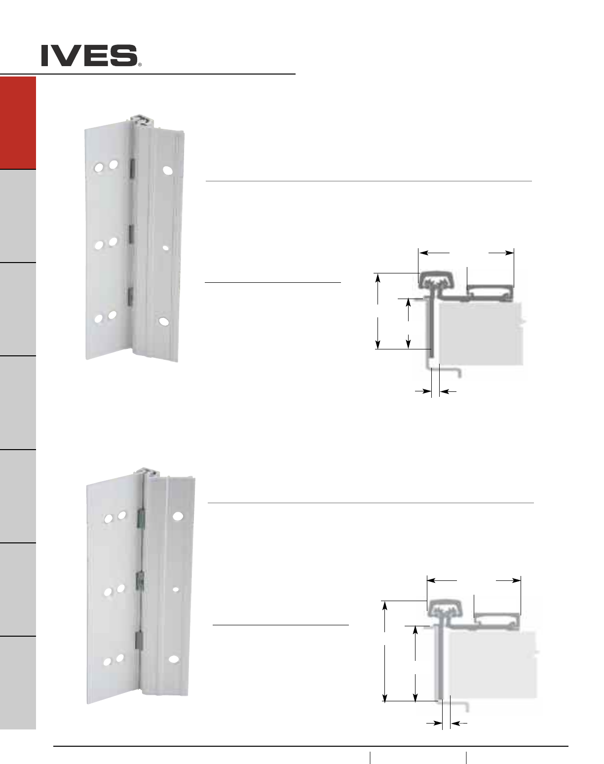
A20
USA 1.877.671.7011 Canada 1.905.403.1800 www.ives.ingersollrand.com
Continuous Hinges
B
Pulls & Plates
A20
Hinges & Pivots
C
Flush Bolts & Coordinators
D
Latches, Catches & Bolts
E
Stops
F
Exterior Hardware
G
Miscellaneous Hardware
053HD Half Surface Continuous Hinge
•Half surface for retrofit or new construction
• Non-handed
• Frame leaf depth 1-9/16"
• 1/8" door inset
Standard lengths 83", 85", 95", 120"
Standard Mounting Hardware
12-24 x 1/2" steel self tapping screw
1/4-20 x 1-1/2" AL Sex Bolt
1/4-20 x 1" Steel Shoulder Bolt
12-24 x 3/4" Steel Self Drilling Shoulder Bolt
Optional SEC-Security Fasteners available
054HD Half Surface Continuous Hinge
• Half surface for retrofit or new construction
• Non-handed
• Frame leaf depth 1-15/16"
• 1/8" door inset
Standard lengths 83", 85", 95", 120"
Standard Mounting Hardware
12-24 x 1/2" steel self tapping screw
1/4-20 x 1-1/2" AL Sex Bolt
1/4-20 x 1" Steel Shoulder Bolt
12-24 x 3/4" Steel Self Drilling Shoulder Bolt
Optional SEC-Security Fasteners available
Finishes
Clear (CL), Dark Bronze (DB)
Custom Anodizing and Painting are
available, consult factory.
Finishes
Clear (CL), Dark Bronze (DB)
Custom Anodizing and Painting are
available, consult factory.
2-1/8"
1-5/32"
2-9/32"
1-9/16"
5/32" Clearance for Square Edge Door
3/16" Clearance For Beveled Edge Door
2-1/8"
1-5/32"
2-5/8"
1-15/16"
5/32" Clearance for Square Edge Door
3/16" Clearance For Beveled Edge Door
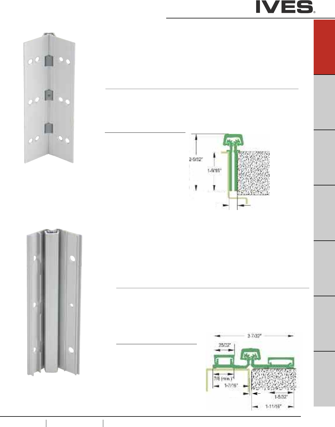
USA 1.877.671.7011 Canada 1.905.403.1800 www.ives.ingersollrand.com
Continuous Hinges
B
Pulls & Plates
A21
Hinges & Pivots
C
Flush Bolts & Coordinators
D
Latches, Catches & Bolts
E
Stops
F
Exterior Hardware
G
Miscellaneous Hardware
A21
157HD Full Surface, Center Pivot
Aluminum Geared Continuous Hinge
• Non Handed
• Narrow Frame
• 1/16" Door Inset
• 48" Maximum Door Width
• Beveled or Square Edge Doors
For Doors Weighing up to 600 pounds
Standard lengths 83", 85", 95", 120"
Standard Mounting Hardware
12-24 X 1/2" Steel Self Tapping Screws,
1/4-20 X 1-1/2" AL Sex Bolt, 1/4-20 X 1" Steel Shoulder Bolt,
12-24 X 3/4” Steel Self Drilling,
Optional SEC - Security Fasteners Available
Finishes
Clear (CL), Dark Bronze (DB)
Custom Anodizing and Painting are
available, consult factory.
112HD Full Moritse Aluminum Geared Continuous Hinge
• Non Handed
•Flush Mounted, No Inset
• 48" Maximum Door Width
• Beveled or Square Edge Doors
For Doors Weighing up to 450 pounds without reinforcing,
600 pounds with reinforcing
Standard lengths 83", 85", 95", 120"
Standard Mounting Hardware
12-24 X 3/4" Steel Self Drilling, Self Tapping Screws
Optional WD - Wood Screws or SEC - Security Fasteners Available
Finishes
Clear (CL), Dark Bronze (DB)
Custom Anodizing and Painting are
available, consult factory.
1/16" Clearance for Square Edge Door
3/32" Clearance For Beveled Edge Door
5/16" Clearance for Square Edge Door
1/32" Clearance For Beveled Edge Door
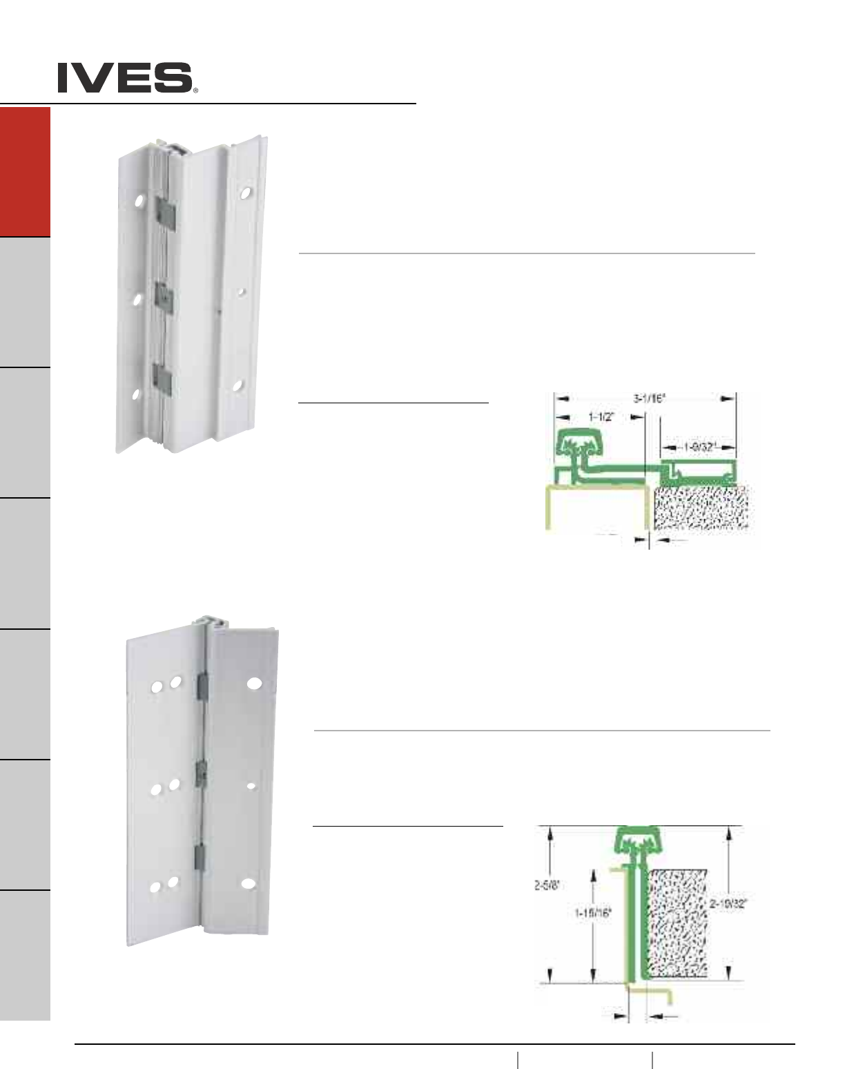
A22
USA 1.877.671.7011 Canada 1.905.403.1800 www.ives.ingersollrand.com
Continuous Hinges
B
Pulls & Plates
A22
Hinges & Pivots
C
Flush Bolts & Coordinators
D
Latches, Catches & Bolts
E
Stops
F
Exterior Hardware
G
Miscellaneous Hardware
210HD Full Surface, Swing Clear
Aluminum Geared Continuous Hinge
• Non Handed
• 1/32" Door Inset
• 48" Maximum Door Width
• Beveled or Square Edge Doors
For Doors Weighing up to 600 pounds
Standard lengths 83", 85", 95", 120"
Standard Mounting Hardware
12-24 X 1/2" Steel Self Tapping Screws,
1/4-20 X 1-1/2" AL Sex Bolt
1/4-20 X 1" Steel
Shoulder Bolt, 12-24 X 3/4" Steel Self Drilling,
Optional SEC - Security Fasteners Available
Finishes
Clear (CL), Dark Bronze (DB)
Custom Anodizing and Painting are
available, consult factory.
224HD Full Mortise Aluminum Geared Continuous Hinge
• Non Handed
• Door Edge Protector
• 48" Maximum Door Width
• 1/16" Door Inset
• Beveled or Square Edge Doors
For Doors Weighing up to 450 pounds without reinforcing,
600 pounds with reinforcing
Standard lengths 83", 85", 95", 120"
Standard Mounting Hardware
12-24 X 3/4" Steel Self Drilling, Self Tapping Screws
Optional WD - Wood Screws or SEC - Security Fasteners Available
Finishes
Clear (CL), Dark Bronze (DB)
Custom Anodizing and Painting are
available, consult factory.
1/16" Clearance for Square Edge Door
3/32" Clearance For Beveled Edge Door
5/16" Clearance for Square Edge Door
1/32" Clearance For Beveled Edge Door
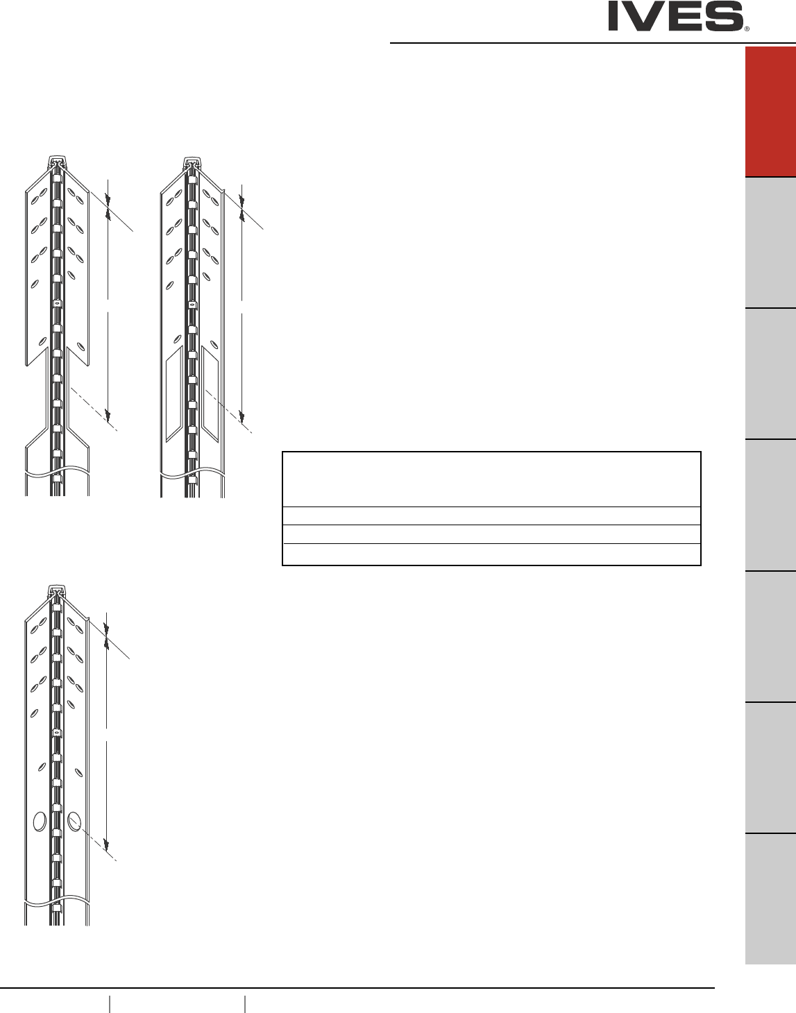
USA 1.877.671.7011 Canada 1.905.403.1800 www.ives.ingersollrand.com
Continuous Hinges
B
Pulls & Plates
A23
Hinges & Pivots
C
Flush Bolts & Coordinators
D
Latches, Catches & Bolts
E
Stops
F
Exterior Hardware
G
Miscellaneous Hardware
A23
Electrical Cutouts
Ives Aluminum Geared Continuous Hinges are available with factory modified
cutouts to accommodate most electrical frame to door requirements. Special
templates are required.
When ordering indicate the following:
1. Opening size.
2. Handing. LH, RH, RHR or LHR.
3. Manufacturer and model number of the electrical product being used. Example;
Von Duprin EPT2
Because clearances may vary between door and frame manufacturer, and locations
can be influenced by the door hardware it is always recommend contacting Ives
Customer Technical for specific template information.
For your general information below are standard locations for Von Duprin EPT2 or
EPT10, and monitor switch.
EPT
112HD
From Top Edge of Door to Center Line of Cut-Out
Standard 112HD 224HD 112HD/224HD
Length EPT EPT TW
83" 30" 30" 41-1/2"
85" 32" 32" 42-1/2"
95" 42" 42" 57-3/4"
120" 67" 67" 81-25/32"
“C EPT”
L
T
op of
hinge/door
T
Top of
hinge/door
2
“C TW”
L
EPT
224HD
“C EPT”
L
Top of
hinge/door
T
TW
112HD
224HD

A24
USA 1.877.671.7011 Canada 1.905.403.1800 www.ives.ingersollrand.com
Continuous Hinges
B
Pulls & Plates
A24
Hinges & Pivots
C
Flush Bolts & Coordinators
D
Latches, Catches & Bolts
E
Stops
F
Exterior Hardware
G
Miscellaneous Hardware
General Information
Standard Lengths
83", 85", 95", 120"
Custom lengths are available up to 120", consult factory.
Finishes
US32D (630) Satin Stainless Steel
USP (600) Steel, Primed for Paint
Barrel Type
Twin Self Lubricated Nylon Bearings with Stainless Steel Pin.
Door Weight
Each hinge can hold a door up to 600 lbs (Rivet nuts recommended) and a max door width of 4'0".
ANSI Certified
All Ives Pin and Barrel Hinges certified to ANSI 156.26, Grade 1.
UL Listed
All Ives Steel and Stainless Steel Pin and Barrel Hinges are tested and approved UL 10C (3 hr).
Field Modifications
All Ives Pin and Barrel Continuous Hinges can be cut to length during installation. If more than 6" from
bottom of hinge, additional modifications may be necessary.
Electrification Options
Only available for the Full Mortise Hinges
Electric Power Transfer (EPT)
Electric power transfer provides a means of transferring power from the door frame to the edge of a
swinging door. Ives Continuous Hinges provide cut outs to fit Von Duprin EPT-2, EPT-10 and
PNT-1 devices. Consult factory for other EPT cut out options.
Electrical Through-Wire (TW)
Provides electric power transfer from the frame to the door in order to supply power to an electrified
mortise or cylindrical locks, exit devices with electric latch retraction, and/or electric strikes (pairs of
doors). Through-wire is rated for 3.5 amp continuous and 16 amp pulse. Ives thru-wire are fully
compatible with 4 wire and 8 wire installations.
Pin and Barrel Hinges

USA 1.877.671.7011 Canada 1.905.403.1800 www.ives.ingersollrand.com
Continuous Hinges
B
Pulls & Plates
A25
Hinges & Pivots
C
Flush Bolts & Coordinators
D
Latches, Catches & Bolts
E
Stops
F
Exterior Hardware
G
Miscellaneous Hardware
A25
How to Order:
Model
Stainless Steel
700 Full Mortise
702 Full Surface - Center Pivot
705 Full Mortise - Full Wrap
711 Full Surface - Swing Clear
715 Full Mortise - Half Wrap
Steel
600 Full Mortise
602 Full Surface - Center Pivot
611 Full Surface - Swing Clear
Finish
Stainless Steel
US32D (630)
Steel
USP (600) Primed
Length
83"
85"
95"
120"
Options
*EPT Electric Power Transfer Prep
*TW8 Electric Through Wire
*TW4M, TW8M Electric Through Wire + Monitoring
SF Security Fasteners - Torx
WD Wood Fasteners
* Full Mortise Models Only
____ - ____ - ____ - ____
700 US32D 83 EPT
Pin and Barrel Hinges
Other lengths available up to 120”, consult factory. Handing is required.

A26
USA 1.877.671.7011 Canada 1.905.403.1800 www.ives.ingersollrand.com
Continuous Hinges
B
Pulls & Plates
A26
Hinges & Pivots
C
Flush Bolts & Coordinators
D
Latches, Catches & Bolts
E
Stops
F
Exterior Hardware
G
Miscellaneous Hardware
SINGLE DOOR
Door Under-Sizing
Hinge-Side Lock-Side Frame Beveled Door Square Beveled
Model Clearance Clearance Irregularity Clearance Edged Edged
600 1/4" 1/8" 1/32" 1/32" 13/32" 7/16"
602 1/8" 1/8" 1/32" 1/32" 9/32" 5/16"
700 1/4" 1/8" 1/32" 1/32" 13/32" 7/16"
702 1/8" 1/8" 1/32" 1/32" 9/32" 5/16"
705 3/8" 1/8" 1/32" 1/32" 17/32" 9/16"
705* 1/2" 1/8" 1/32" 1/32" 21/32" 11/16"
711 7/32" 1/8" 1/32" 1/32" 3/8" 13/32"
715 1/4" 1/8" 1/32" 1/32" 13/32" 7/16"
PAIR OF DOORS
Door Under-Sizing
Square Square Beveled Beveled
Hinge-Side Lock-Side Frame Beveled Door Edged Edged Edged Edged
Model Clearance Clearance Irregularity Clearance Total Each Door Total Each Door
600 1/4" 3/16" 1/16" 1/16" 3/4" 3/8" 13/16" 13/32"
602 1/8" 3/16" 1/16" 1/16" 1/2" 1/4" 9/16" 9/32"
700 1/4" 3/16" 1/16" 1/16" 3/4" 3/8" 13/16" 13/32"
702 1/8" 3/16" 1/16" 1/16" 1/2" 1/4" 9/16" 9/32"
705 3/8" 3/16" 1/16" 1/16" 1" 1/2" 1-1/16" 17/32"
705* 1/2" 3/16" 1/16" 1/16" 1-1/4" 5/8" 1-5/16" 21/32"
711 7/32" 3/16" 1/16" 1/16" 11/16" 11/32" 3/4" 3/8"
715 1/4" 3/16" 1/16" 1/16" 3/4" 3/8" 13/16" 13/32"
Hinge
Side
Clearance
1/32”
Frame
Irregularity
1/8” Hinge
Side
Clearance
Hinge
Side
Clearance
1/16”
Frame
Irregularity
3/16”
* Use the Adjusta-Studs with 705
* Use the Adjusta-Studs with 705
Pin and Barrel Hinges - Clearance Requirements
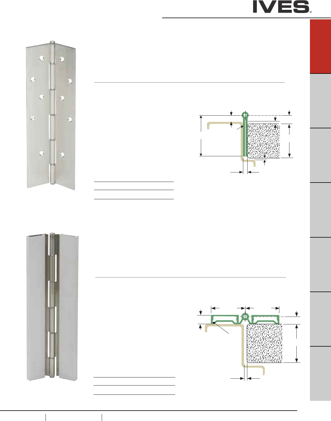
USA 1.877.671.7011 Canada 1.905.403.1800 www.ives.ingersollrand.com
Continuous Hinges
B
Pulls & Plates
A27
Hinges & Pivots
C
Flush Bolts & Coordinators
D
Latches, Catches & Bolts
E
Stops
F
Exterior Hardware
G
Miscellaneous Hardware
A27
” 4 / 3 -
1
”
2
/
1
s s e n k c i h T e g
n
i H ” 5 7
0
. 0 A G
”4
/ 1
” 6 1 / 1
”4/ 1- 2
” 8 /
1
”
8 / 3
0
[5.6] HINGE ALLOWANCE
2 [50.8]
G
0.060"
[
600
700 Full Mortise Pin and Barrel Continuous Hinge
For Doors Weighing up to 600 pounds
• Non Handed
•1/8” Inset
• 48" Maximum Door Width
• Non Handed
• Bevel or Square Edge Door
Standard lengths 83", 85", 95", 120"
Standard Mounting Hardware
#10 X 1/2" Self Drilling Self Tapping Screws,
#10 X 1" Wood Screws
Optional SEC - Security Fasteners Available
Material
600- 1012 Cold-Rolled Steel
700- 14 Gauge Type 304 Stainless Steel
1/4" Diameter 304 Stainless Pin with
Nylon Split Bearing
Finishes 600 700
BHMA 600 630
US Numbers USP US32D
Custom Paint Available, on 600
consult factory.
” 4 /
3 -
1
”
8
/ 3
”
8
/ 1
1-3/4” 1-3/4”
s
se
nk
c
i
h
T
e
gni
H
”
5
70.0
AG
7/16”
602
702 Full Surface Pin and Barrel Continuous Hinge
For Doors Weighing up to 600 pounds
• Non Handed
• Flush Mounted, No Inset
• 48" Maximum Door Width
• Bevel or Square Edge Door
Standard lengths 83", 85", 95", 120"
Standard Mounting Hardware
1/4"-20 x 3/4" Self Drilling Self Tapping Screws,
Cover Clips
Optional SEC - Security Fasteners Available
Material
602- 1012 Cold-Rolled Steel
702 - 14 Gauge Type 304 Stainless Steel
1/4" Diameter 304 Stainless Pin with
Nylon Split Bearing
Brushed Aluminum Leaf Covers
Finishes 602 702
BHMA 600 630
US Numbers USP US32D
Custom Paint Available, on 602
consult factory
Clearance for
Square Edge
5/16" Clearance for
Beveled Edge
Clearance for
Square Edge
5/32" Clearance for
Beveled Edge
1/8"
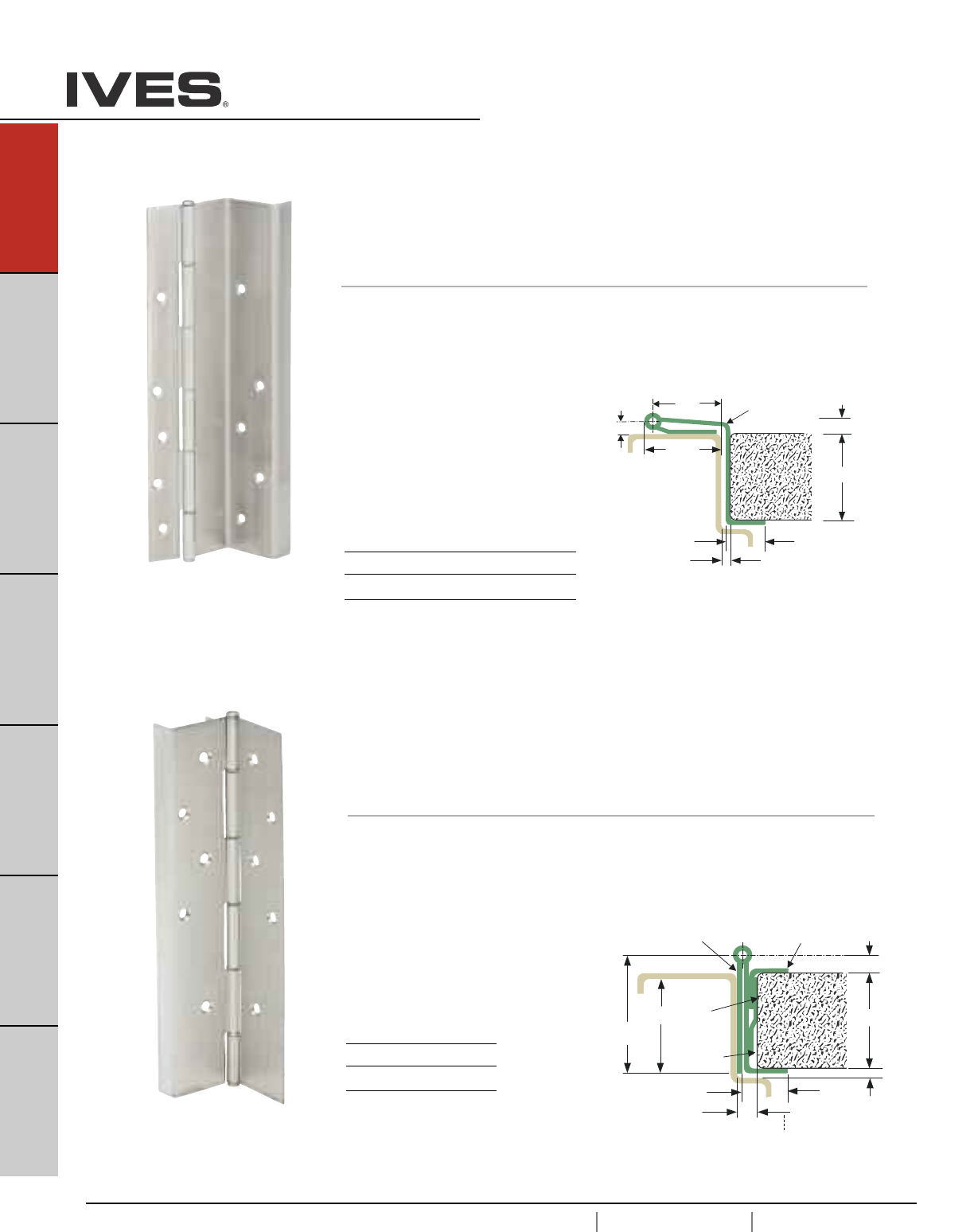
A28
USA 1.877.671.7011 Canada 1.905.403.1800 www.ives.ingersollrand.com
Continuous Hinges
B
Pulls & Plates
A28
Hinges & Pivots
C
Flush Bolts & Coordinators
D
Latches, Catches & Bolts
E
Stops
F
Exterior Hardware
G
Miscellaneous Hardware
”
4 / 3
- 1
”4/1-2
”8/7-1
” 8
/ 3
s s e n k c i h T e
g
n i H ” 5 7 0 . 0 A G
”8/
3
” 4
3/16”
/ 3
”
5 2
6
0
. 0 A G
”570.0 AG
Note:
Provide
0.125”
Adjustment
705 Full Moritse, Full Wrap
Pin and Barrel Continuous Hinge
For Doors Weighing up to 600 pounds
• Non Handed
• Flush Mounted, No Inset
• 48" Maximum Door Width
• Full Wrap Edge Guard
• Bevel or Square Edge Door
Standard lengths 83", 85", 95", 120"
Standard Mounting Hardware
#10 X 1/2" Self Drilling Self Tapping Screws, #10 X 1" Wood Screws
Adjusta-stud 1-3/8"
with 10-32 internal thread
Optional SEC - Security Fasteners Available.
Material
14 Gauge Type 304 Stainless Steel
1/4" diameter 304 stanless pin with
nylon split bearings
Finishes
BHMA 630
US Numbers US32D
”
4 / 3
-
1
”
8 /
3
” 2
3
/ 5
”
4 / 3
e
g
n
i H
”
5 7
0 . 0 A G
s s e n
k
c i h T
”
4 /
1
”
8
/ 3 - 1
”
16
/
9
-
1
611
711 Swing Clear Pin and Barrel Continuous Hinge
For Doors Weighing up to 600 pounds
• Non Handed
•Edge Guard
• 48" Maximum Door Width
• Square Edge Door
Standard lengths 83", 85", 95", 120"
Standard Mounting Hardware
#10 X 1/2" Self Drilling Self Tapping Screws
#10 X 1" Wood Screws
Optional SEC - Security Fasteners Available
Material
611- 1012 Cold-Rolled Steel
711- 14 Gauge Type 304 Stainless Steel
1/4" diameter 304 stanless pin with
nylon split bearings
Finishes 611 711
BHMA 600 630
US Numbers USP US32D
Custom Paint Available, on 611
consult factory
*
Adjusta-Stud
allows up to 3/8” width adjustment which ensures proper alignment and easy installation.
Adjusta-Stud also makes it possible for future adjustments of the door on the frame through repositioning.
7/32" Clearance for
Square Edge
1/4" Clearance for
Beveled Edge
3/8" Clearance for
Square Edge
13/32" Clearance for
Beveled Edge
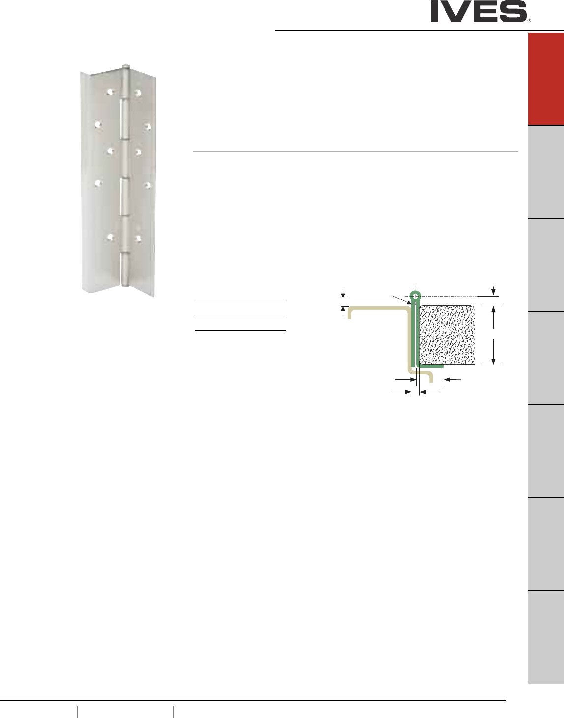
USA 1.877.671.7011 Canada 1.905.403.1800 www.ives.ingersollrand.com
Continuous Hinges
B
Pulls & Plates
A29
Hinges & Pivots
C
Flush Bolts & Coordinators
D
Latches, Catches & Bolts
E
Stops
F
Exterior Hardware
G
Miscellaneous Hardware
A29
”
4 / 3
-
1
”
8 / 3
” 4 / 1
”
4 /
3
e g
n i H
” 5
7 0 . 0
A
G
s s
e
n
k
c i h
T
” 4 / 1
715 Full Mortise, Half Wrap
Pin and Barrel Continuous Hinge
For Doors Weighing up to 600 pounds
• Non Handed
• Flush Mounted, No Inset
• Half Wrap Edge Guard
• 48" Maximum Door Width
• Square Edge Door
Standard lengths 83", 85", 95", 120"
Standard Mounting Hardware
#10 X 1/2" Self Drilling Tek Screws,
#10 X 1" Wood Screws
Optional SEC - Security Fasteners Available
Material
14 Gauge Type 304 Stainless Steel
1/4" diameter 304 stanless pin with
nylon split bearings
Finishes
BHMA 630
US Numbers US32D
Custom Paint Available,
consult factory
1/4" Clearance for
Square Edge
4/32" Clearance for
Beveled Edge

Electrical Cutouts
Ives Pin & Barrel Continuous Hinges are available with factory modified cutouts to
accommodate most electrical frame to door requirements. Special templates
are required.
When ordering indicate the following:
1. Opening size.
2. Handing. LH, RH, RHR or LHR.
3. Manufacturer and model number of the electrical product being used.
Example; Von Duprin EPT2
Because clearances may vary between door and frame manufacturer, and
locations can be influenced by the door hardware it is always recommend
contacting Ives Customer Technical for specific template information.
For your general information following are standard locations for Von Duprin
EPT2 or EPT10, and TW (through wire)
Standard centerline cutout locations
A30
USA 1.877.671.7011 Canada 1.905.403.1800 www.ives.ingersollrand.com
Continuous Hinges
B
Pulls & Plates
A30
Hinges & Pivots
C
Flush Bolts & Coordinators
D
Latches, Catches & Bolts
E
Stops
F
Exterior Hardware
G
Miscellaneous Hardware
Top of door
“C EPT”
L
EPT
600/700
T
op of door
“C TW”
L
TW
600/700
From Top Edge o top of Door to Center Line of Cut-Out
Standard
Length EPT TW
83" 30" 43-19/32"
85" 32" 45-17/32"
95" 42" 55-17/32"
120" 67" 80-17/32"
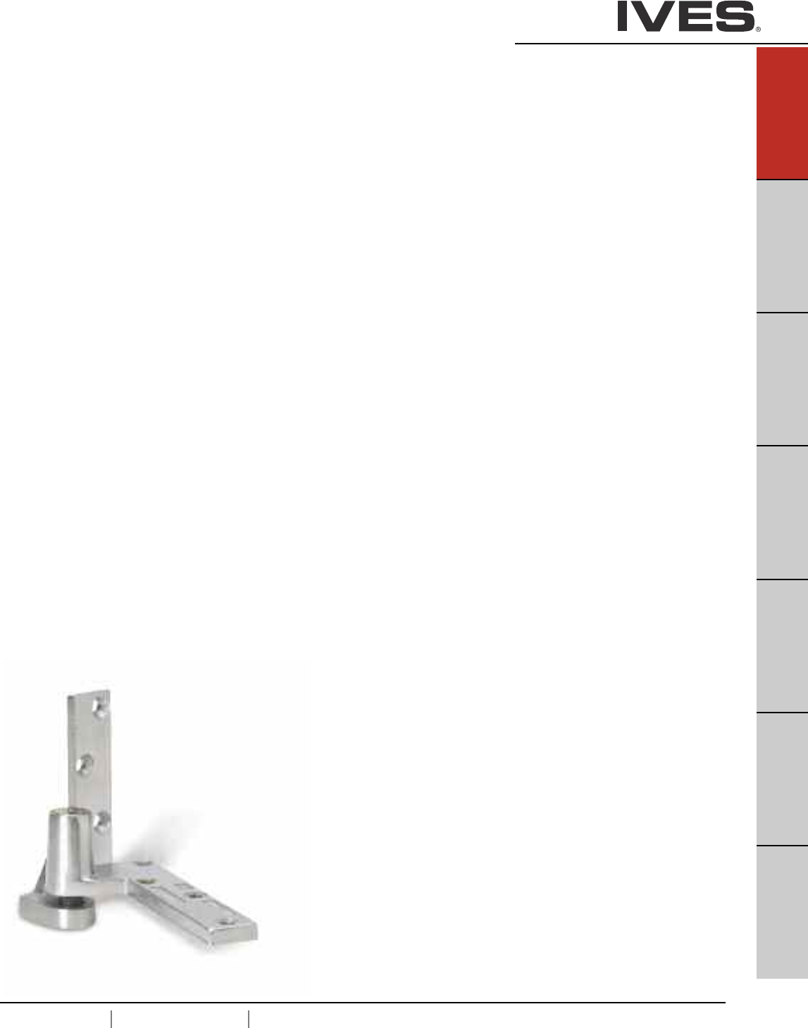
USA 1.877.671.7011 Canada 1.905.403.1800 www.ives.ingersollrand.com
Pivots
B
Pulls & Plates
A31
Hinges & Pivots
C
Flush Bolts & Coordinators
D
Latches, Catches & Bolts
E
Stops
F
Exterior Hardware
G
Miscellaneous Hardware
A31
The door rests on the bottom pivot in this application. This reduces
the stress on the frame by distributing the weight of the door
throughout the floor and structure. By taking advantage of the
strength of the structure, this makes a pivot the ideal solution for your
heavy doors. Center and pocket pivots also provide an aesthetic
option for your opening.
Pivots Table Of Contents
page
General Information . . . . . . . . . . . . . . . . . . . . . . . . . . . . . . . . . . . . . . . .A32
Selection Chart and Parts Reference . . . . . . . . . . . . . . . . . . . . . . . . . . . .A32
How To Order . . . . . . . . . . . . . . . . . . . . . . . . . . . . . . . . . . . . . . . . . . . . .A33
7212 . . . . . . . . . . . . . . . .3/4" Offset . . . . . . . . . . . . . . . . . . . . . . . . .A34
7212V . . . . . . . . . . . . . . .3/4" Offset . . . . . . . . . . . . . . . . . . . . . . . . .A34
7215, 7215F . . . . . . . . . .3/4" Offset . . . . . . . . . . . . . . . . . . . . . . . . .A35
7222 . . . . . . . . . . . . . . . .3/4" Offset . . . . . . . . . . . . . . . . . . . . . . . . .A36
7226, 7226F . . . . . . . . . .3/4" Offset . . . . . . . . . . . . . . . . . . . . . . . . .A37
7227, 7227F . . . . . . . . . .3/4" Offset . . . . . . . . . . . . . . . . . . . . . . . . .A38
7230F . . . . . . . . . . . . . . .3/4" Offset . . . . . . . . . . . . . . . . . . . . . . . . .A39
7237F . . . . . . . . . . . . . . .3/4" Offset . . . . . . . . . . . . . . . . . . . . . . . . .A40
7244F . . . . . . . . . . . . . . .1-1/2" Offset . . . . . . . . . . . . . . . . . . . . . . .A41
7245F . . . . . . . . . . . . . . .1-1/2" Offset . . . . . . . . . . . . . . . . . . . . . . . .A42
7212-722V-7222 INT . . . .Intermediate . . . . . . . . . . . . . . . . . . . . . . . . .A43
7215-7226-7227 INT . . . .Intermediate . . . . . . . . . . . . . . . . . . . . . . . . .A43
7215F-7226F-7227F INT .Intermediate . . . . . . . . . . . . . . . . . . . . . . . . .A43
7230F-7237F INT . . . . . . .Intermediate . . . . . . . . . . . . . . . . . . . . . . . . .A44
7244F-7245F INT . . . . . . .Intermediate . . . . . . . . . . . . . . . . . . . . . . . . .A44
7215PT-7226PT-7227PT .Intermediate, Electrified . . . . . . . . . . . . . . . .A45
7253 . . . . . . . . . . . . . . . .Center Hung . . . . . . . . . . . . . . . . . . . . . . . .A46
7255 . . . . . . . . . . . . . . . .Center Hung . . . . . . . . . . . . . . . . . . . . . . . .A47
7255J . . . . . . . . . . . . . . .Center Hung . . . . . . . . . . . . . . . . . . . . . . . .A47
7256 . . . . . . . . . . . . . . . .Center Hung . . . . . . . . . . . . . . . . . . . . . . . .A48
7259 . . . . . . . . . . . . . . . .Center Hung . . . . . . . . . . . . . . . . . . . . . . . .A49
Pocket Pivots
91105 . . . . . . . . . . . . . . . . . . . . . . . . . . . . . . . . . . . . . . . . . . . . . . . . . . .A50
91105F . . . . . . . . . . . . . . . . . . . . . . . . . . . . . . . . . . . . . . . . . . . . . . . . .A50
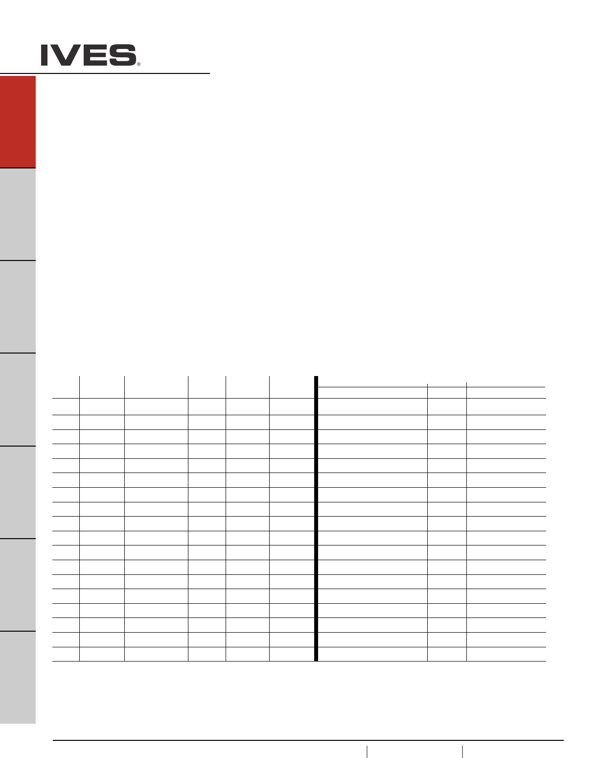
A32
USA 1.877.671.7011 Canada 1.905.403.1800 www.ives.ingersollrand.com
Pivots
B
Pulls & Plates
A32
Hinges & Pivots
C
Flush Bolts & Coordinators
D
Latches, Catches & Bolts
E
Stops
F
Exterior Hardware
G
Miscellaneous Hardware
7200 Series Pivots
General Information:
Complete line of 3/4" offset, 1-1/2" offset, center hung, intermediate and
power transfer pivots with all exposed parts made of brass or stainless steel
for maximum corrosion resistance.
High strength brass and stainless steel forgings, and castings for rated and
non-rated doors combined with precision bearings for smooth operation.
Stainless steel machine screws and wood screws standard. Positive locking
vertical adjustment mechanism allows the installer to precisely position the
door and balance the load.
Last digit in pivot set number reflects the maximum door weight in
hundreds of pound, e.g., 7215 = 500 pounds. For sets designated as
“heavy duty”, add 1,000 pounds, e.g., 7237F HD set = 1700 pounds.
Pivots for lead lined doors are available, consult factory.
Pivot Pivot Type Bottom Mounting UL Listing Max. Door Handing When Ordering Separate Parts
Set Style Weight Top Bottom Intermediate
7212 3/4" Offset Jamb Mounted none 200 LH or RH 7212-7215-7222-7226-7227 TOP 7212 BTM 7212-7212V-7222 INT
7212V 3/4" Offset Jamb Mounted none 200 LH or RH 7212V TOP 7212 BTM 7212-7212V-7222 INT
7215 3/4" Offset Jamb Mounted 20 Minute 500 LH or RH 7212-7215-7222-7226-7227 TOP 7215 BTM 7215-7226-7227 INT
7215F 3/4" Offset Jamb Mounted 3 Hour 500 LH or RH 7215F-7226F-7227F TOP 7215F BTM 7215F-7226F-7227F INT
7222 3/4" Offset Floor Mounted none 200 LH or RH 7212-7215-7222-7226-7227 TOP 7222 BTM 7212-7212V-7222 INT
7226 3/4" Offset Floor Mounted 20 Minute 600 Non-Handed 7212-7215-7222-7226-7227 TOP 7226 BTM 7215-7226-7227 INT
7226F 3/4" Offset Floor Mounted 3 Hour 600 Non-Handed 7215F-7226F-7227F TOP 7226F BTM 7215F-7226F-7227F INT
7227 3/4" Offset Mortise Cement Case 20 Minute 700 Non-Handed 7212-7215-7222-7226-7227 TOP 7227 BTM 7215-7226-7227 INT
7227F 3/4" Offset Mortise Cement Case 3 Hour 700 Non-Handed 7215F-7226F-7227F TOP 7227F BTM 7215-7226-7227 INT
7230F 3/4" Offset Floor Mounted 3 Hour 1,000 Non-Handed 7230F-7237F TOP 7230F BTM 7215F-7226F-7227F INT
7237F 3/4" Offset Mortise Cement Case 3 Hour 1,750 Non-Handed 7230F-7237F TOP 7237F BTM 7230F-7237F INT
7244F 1-1/2" Offset Floor Mounted 3 Hour 400 Non-Handed 7244F-7245F TOP 7244F BTM 7230F-7237F INT
7245F 1-1/2" Offset Mortise Cement Case 3 Hour 500 Non-Handed 7244F-7245F TOP 7245F BTM 7244F-7245F INT
7253 Center Hung Floor Mounted none 300 Non-Handed 7253-7255-7255J-7256 TOP 7253 BTM 7244F-7245F INT
7255 Center Hung Floor Mounted none 500 Non-Handed 7253-7255-7255J-7256 TOP 7255 BTM none
7255J Center Hung Jamb Mounted none 500 Non-Handed 7253-7255-7255J-7256 TOP 7255J BTM none
7256 Center Hung Mortise Cement Case none 600 Non-Handed 7253-7255-7255J-7256 TOP 7256 BTM none
7259 Center Hung Mortise Cement Case none 1,000 Non-Handed 7259 TOP 7259 BTM none
7200 series Pivot Selection Chart

USA 1.877.671.7011 Canada 1.905.403.1800 www.ives.ingersollrand.com
Pivots
B
Pulls & Plates
A33
Hinges & Pivots
C
Flush Bolts & Coordinators
D
Latches, Catches & Bolts
E
Stops
F
Exterior Hardware
G
Miscellaneous Hardware
A33
How to Order:
____ - ___ - ____- ____
Pivot:
7212
7212V
7215
7215F
7222
7226
7226F
7227
7227F
7230F
7237F
7244F
7245F
7253
7255
7255J
7256
7259
Pivot Style:
Blank Top and bottom set
TOP Top pivot only
BTM Bottom pivot only
INT Intermediate pivot only
PT INT Power transfer intermendiate pivot only
Hand:
LH Left hand door
RH Right hand door
Finish:
US3
US4
US10
US10B
US26
US26D
SP4
SP10
SP28
SP313
SPBLK
USP
optional finishes are available, consult factory
7212 LH US3
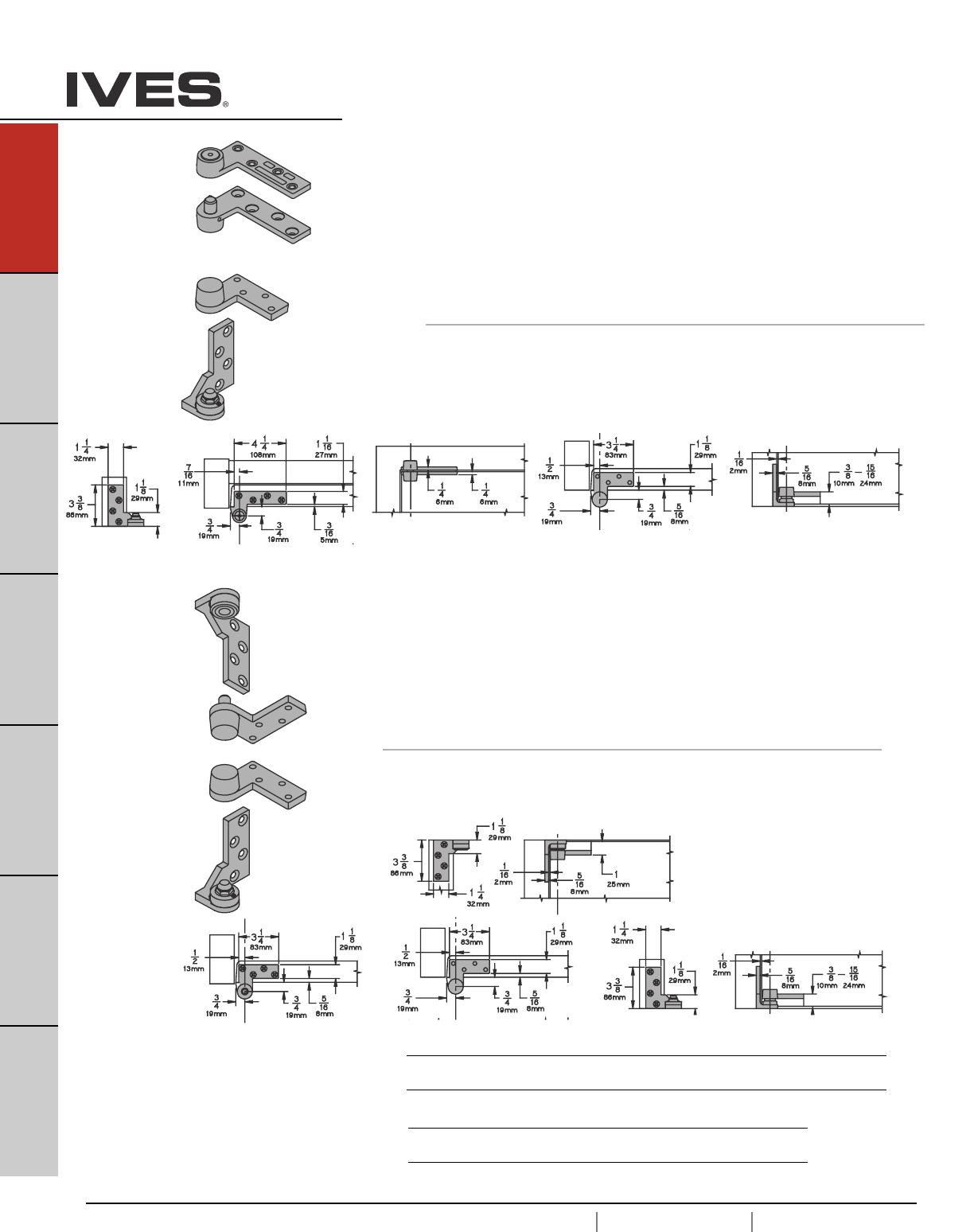
A34
USA 1.877.671.7011 Canada 1.905.403.1800 www.ives.ingersollrand.com
Pivots
B
Pulls & Plates
A34
Hinges & Pivots
C
Flush Bolts & Coordinators
D
Latches, Catches & Bolts
E
Stops
F
Exterior Hardware
G
Miscellaneous Hardware
7212V Pivot Set
7212 3/4" Offset Pivot
• Handed
•Top, header mount
• Bottom, jamb mount
• Use with 1-3/4" minimum door thickness, with 1/8" bevel in 2"
• Maximum door load 200 pounds
• Vertical adjustment range 3/16", with positive locking
Optional 7212-7212V-7222 Intermediate Pivot (handed) for each
additional 100 pounds or doors over 7'. See page A47.
7212V 3/4" Offset Pivot
• Handed
• Top, jamb mount
• Bottom, jamb mount
• Use with 1-3/4" minimum door thickness, with 1/8" bevel in 2"
• Maximum door load 200 pounds
• Vertical adjustment range 3/16", with positive locking
Optional 7212-7212V-7222 Intermediate Pivot (handed) for each
additional 100 pounds or doors over 7'. See page A47.
Plated Finishes brass
US Number US3 US4 US10 US10B US26 US26D
BHMA Number 605 606 612 613 625 626
Painted Finishes brass
US Number SP4 SP10 SP28 SP313 SPBLK
BHMA Number 706 691 689 695 622
Meets ANSI/BHMA A156.4 C07131
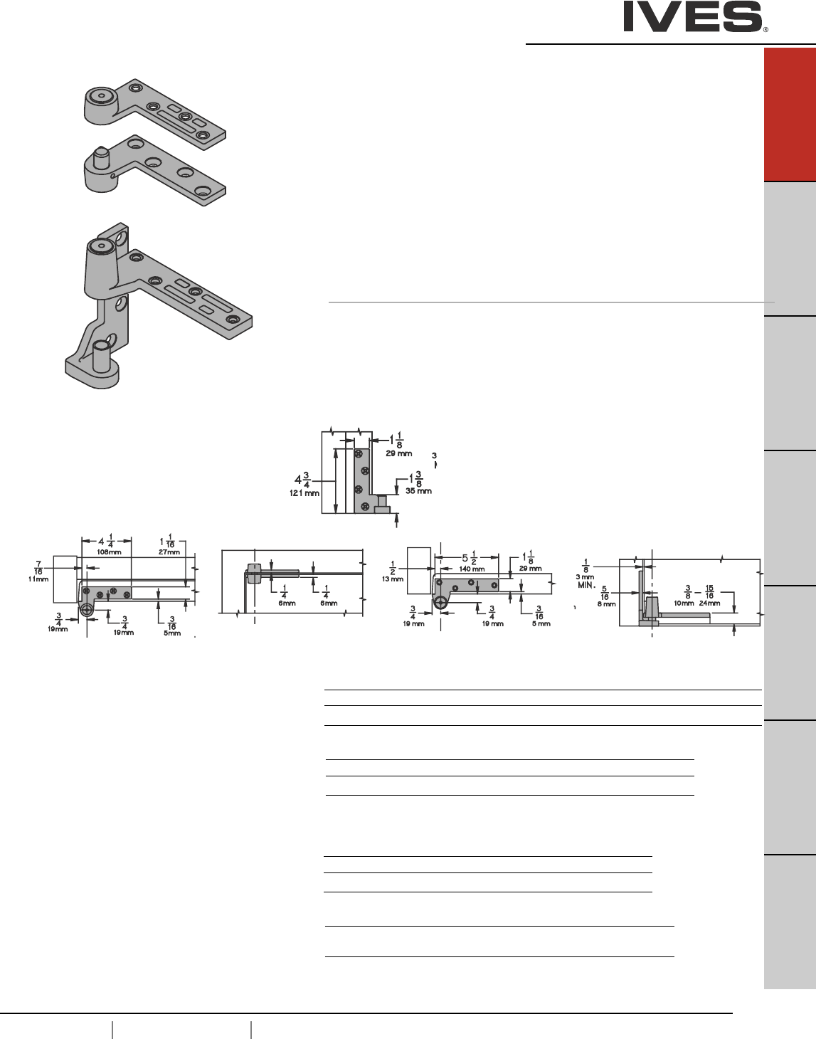
USA 1.877.671.7011 Canada 1.905.403.1800 www.ives.ingersollrand.com
Pivots
B
Pulls & Plates
A35
Hinges & Pivots
C
Flush Bolts & Coordinators
D
Latches, Catches & Bolts
E
Stops
F
Exterior Hardware
G
Miscellaneous Hardware
A35
7215 - Ul Listed 20 minute fire doors
7215F - UL Listed 3 hour fire doors
7215
7215F 3/4" Offset Pivot
• Handed
• Top, header mount
• Bottom, jamb mount
• Use with 1-3/4" minimum door thickness, with 1/8" bevel in 2"
• Maximum door load 500 pounds
• Vertical adjustment range 3/16", with positive locking
• WP - optional weather resistant bottom pivot is modified for
improved corrosion resistance. Available in US26D (626) or
US32D (630) only.
Optional 7215-7226-7227 or 7215F-7226F-7227F Intermediate Pivot
(handed) for each additional 100 pounds or doors over 7'. See page A47.
Optional 7215PT Power Transfer, non-load bearing. See page A49
7215
Plated Finishes brass
US Number US3 US4 US10 US10B US26 US26D
BHMA Number 605 606 612 613 625 626
Painted Finishes brass
US Number SP4 SP10 SP28 SP313 SPBLK
BHMA Number 706 691 689 695 622
7215F
Plated Finishes steel
US Number US3 US10 US32 US32D
BHMA Number 632 639 629 630
Painted Finishes steel
US Number SP4 SP10 SP28 SP313 SPBLK
BHMA Number 706 691 689 695 622
Meets ANSI/BHMA A156.4 C07131
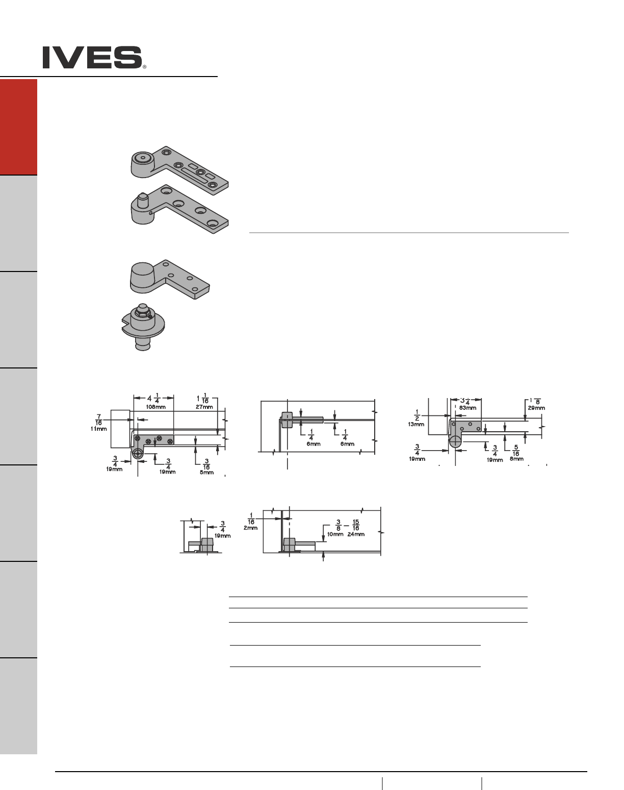
A36
USA 1.877.671.7011 Canada 1.905.403.1800 www.ives.ingersollrand.com
Pivots
B
Pulls & Plates
A36
Hinges & Pivots
C
Flush Bolts & Coordinators
D
Latches, Catches & Bolts
E
Stops
F
Exterior Hardware
G
Miscellaneous Hardware
7222 3/4" Offset Pivot
•Handed
• Top, header mount
• Bottom, base plate mount
• Use with 1-3/4" minimum door thickness, with 1/8" bevel in 2"
• Maximum door load 200 pounds
• Vertical adjustment range 3/16", with positive locking
Optional 7212-7212V-7222 Intermediate Pivot (handed) for each
additional 100 pounds or doors over 7'. See page A47.
Plated Finishes brass
US Number US3 US4 US10 US10B US26 US26D
BHMA Number 605 606 612 613 625 626
Painted Finishes brass
US Number SP4 SP10 SP28 SP313 SPBLK
BHMA Number 706 691 689 695 622
Meets ANSI/BHMA A156.4 C07162
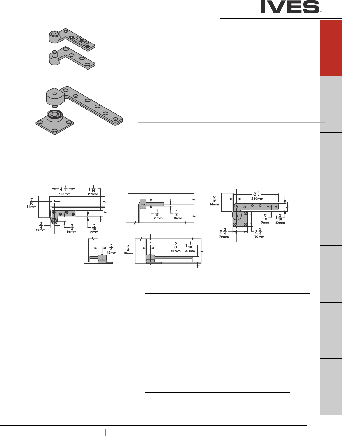
USA 1.877.671.7011 Canada 1.905.403.1800 www.ives.ingersollrand.com
Pivots
B
Pulls & Plates
A37
Hinges & Pivots
C
Flush Bolts & Coordinators
D
Latches, Catches & Bolts
E
Stops
F
Exterior Hardware
G
Miscellaneous Hardware
A37
7226
7226F 3/4" Offset Pivot
• Non-handed
• Top, header mount
• Bottom, base plate mount
• Use with 1-3/4" minimum door thickness, with 1/8" bevel in 2"
• Maximum door load 600 pounds
• Vertical adjustment range 3/16", with positive locking
Optional 7215-7226-7227or 7226F-722 Intermediate Pivot (handed) for each
additional 100 pounds or doors over 7'. See page A47.
Optional 7226PT Power Transfer (four wires), non-load bearing. See page A49
7226 - Ul Listed 20 minute fire doors
7226F - UL Listed 3 hour fire doors
7226
Plated Finishes brass
US Number US3 US4 US10 US10B US26 US26D
BHMA Number 605 606 612 613 625 626
Painted Finishes brass
US Number SP4 SP10 SP28 SP313 SPBLK
BHMA Number 706 691 689 695 622
7226F
Plated Finishes steel
US Number US3 US10 US32 US32D
BHMA Number 632 639 629 630
Painted Finishes steel
US Number SP4 SP10 SP28 SP313 SPBLK
BHMA Number 706 691 689 695 622
Meets ANSI/BHMA A156.4 C07162
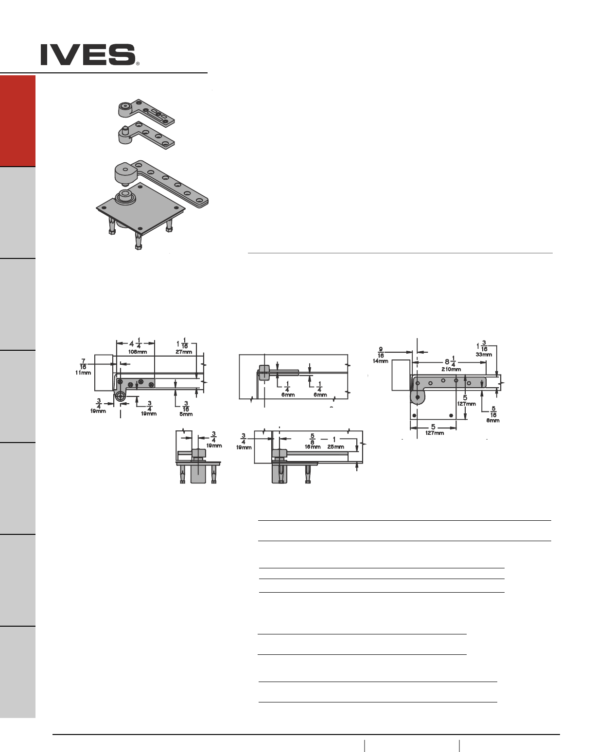
A38
USA 1.877.671.7011 Canada 1.905.403.1800 www.ives.ingersollrand.com
Pivots
B
Pulls & Plates
A38
Hinges & Pivots
C
Flush Bolts & Coordinators
D
Latches, Catches & Bolts
E
Stops
F
Exterior Hardware
G
Miscellaneous Hardware
7227
7227F 3/4" Offset Pivot
• Non-handed
• Top, header mount
• Bottom, base plate mount
• Use with 1-3/4" minimum door thickness, with 1/8" bevel in 2"
• Maximum door load 700 pounds
• Vertical adjustment range 3/16", with positive locking
Optional 7215-7226-7227 or 7215F-7226F-7227F Intermediate Pivot (handed)
for each additional 100 pounds or doors over 7'. See page A47.
Optional 7227PT Power Transfer (four wires), non-load bearing. See page A49.
7227 - Ul Listed 20 minute fire doors
7227F - UL Listed 3 hour fire doors
7227
Plated Finishes brass
US Number US3 US4 US10 US10B US26 US26D
BHMA Number 605 606 612 613 625 626
Painted Finishes brass
US Number SP4 SP10 SP28 SP313 SPBLK
BHMA Number 706 691 689 695 622
7227F
Plated Finishes steel
US Number US3 US10 US32 US32D
BHMA Number 632 639 629 630
Painted Finishes steel
US Number SP4 SP10 SP28 SP313 SPBLK
BHMA Number 706 691 689 695 622
Meets ANSI/BHMA A156.4 C07121
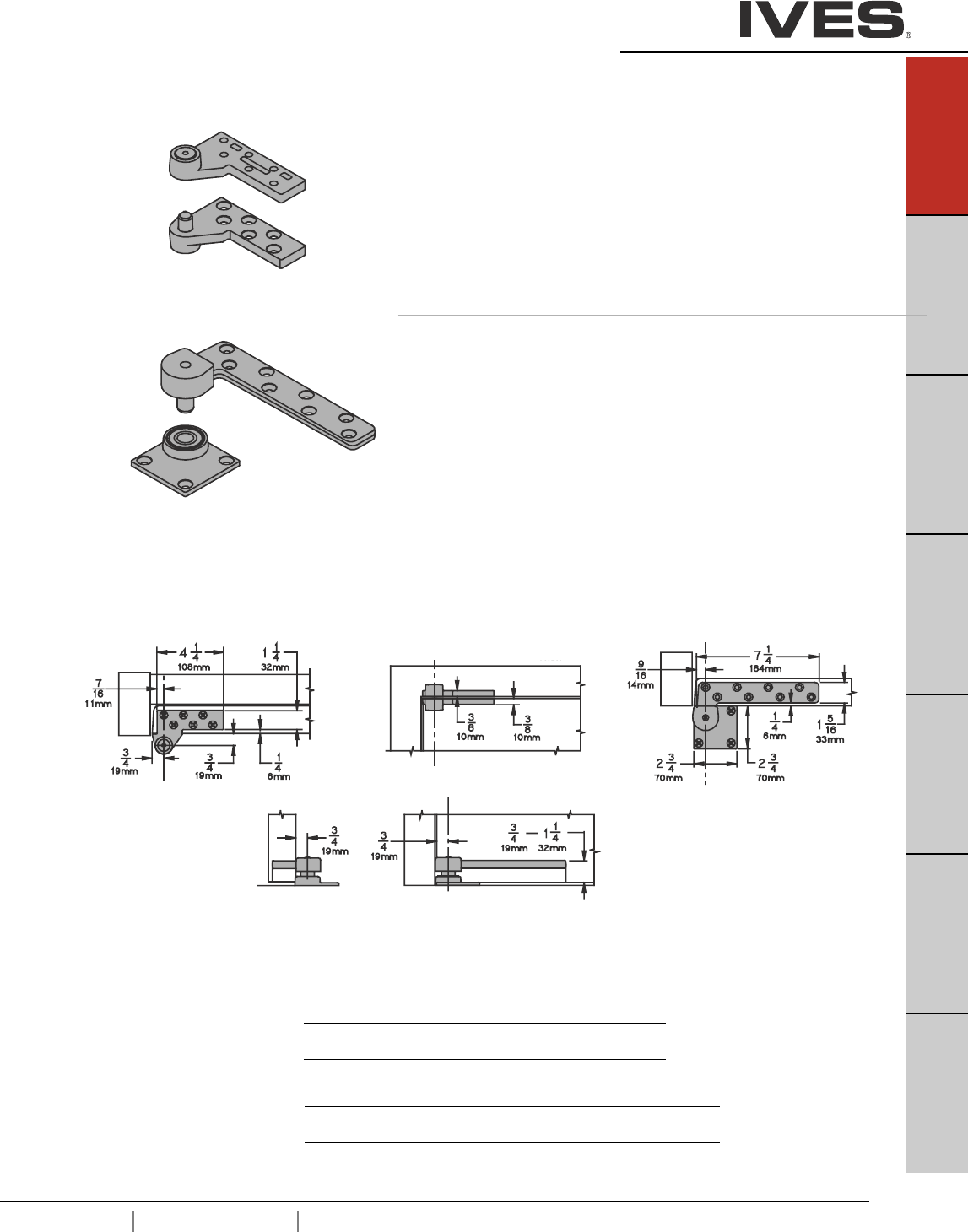
USA 1.877.671.7011 Canada 1.905.403.1800 www.ives.ingersollrand.com
Pivots
B
Pulls & Plates
A39
Hinges & Pivots
C
Flush Bolts & Coordinators
D
Latches, Catches & Bolts
E
Stops
F
Exterior Hardware
G
Miscellaneous Hardware
A39
7230F 3/4" Offset Pivot - Heavy Duty
• Non-Handed
• Top, header mount
• Bottom, base plate mount
• Use with 1-3/4" minimum door thickness, with 1/8" bevel in 2"
• Maximum door load 1,000 pounds
• Vertical adjustment range 3/16", with positive locking
Optional 7230F-7237F Intermediate Pivot (handed) for each
additional 100 pounds or doors over 7'. See page A48.
Meets ANSI/BHMA A156.4 C07162
UL Listed 3 Hour Fire Doors
Plated Finishes steel
US Number US3 US10 US32 US32D
BHMA Number 632 639 629 630
Painted Finishes steel
US Number SP4 SP10 SP28 SP313 SPBLK
BHMA Number 706 691 689 695 622
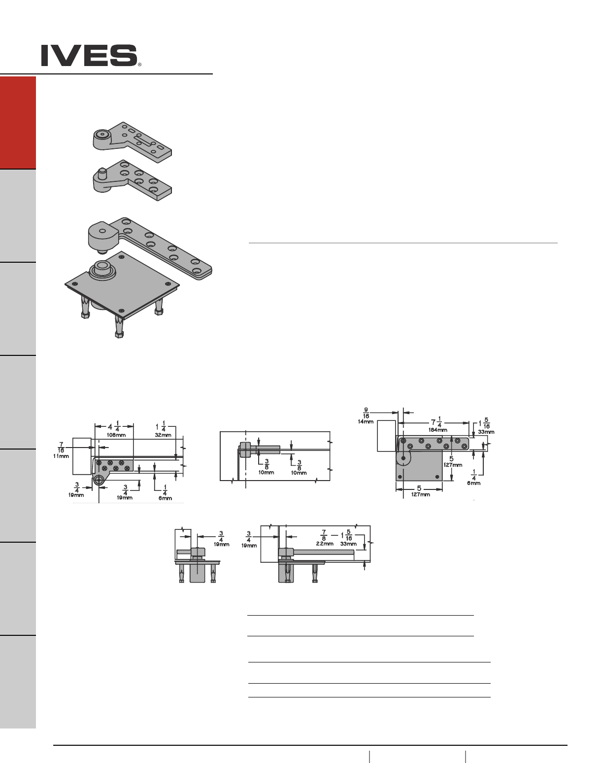
A40
USA 1.877.671.7011 Canada 1.905.403.1800 www.ives.ingersollrand.com
Pivots
B
Pulls & Plates
A40
Hinges & Pivots
C
Flush Bolts & Coordinators
D
Latches, Catches & Bolts
E
Stops
F
Exterior Hardware
G
Miscellaneous Hardware
7237F 3/4" Offset Pivot - Heavy Duty
• Non-Handed
• Top, header mount
• Bottom, mortised cement case mount
• Use with 1-3/4" minimum door thickness, with 1/8" bevel in 2"
• Maximum door load 1,750 pounds
• Vertical adjustment range 3/16", with positive locking
Optional 7230F-7237F Intermediate Pivot (handed) for each
additional 100 pounds or doors over 7'. See page A48.
Meets ANSI/BHMA A156.4 C07111
UL Listed 3 Hour Fire Doors
Plated Finishes steel
US Number US3 US10 US32 US32D
BHMA Number 632 639 629 630
Painted Finishes steel
US Number SP4 SP10 SP28 SP313 SPBLK
BHMA Number 706 691 689 695 622
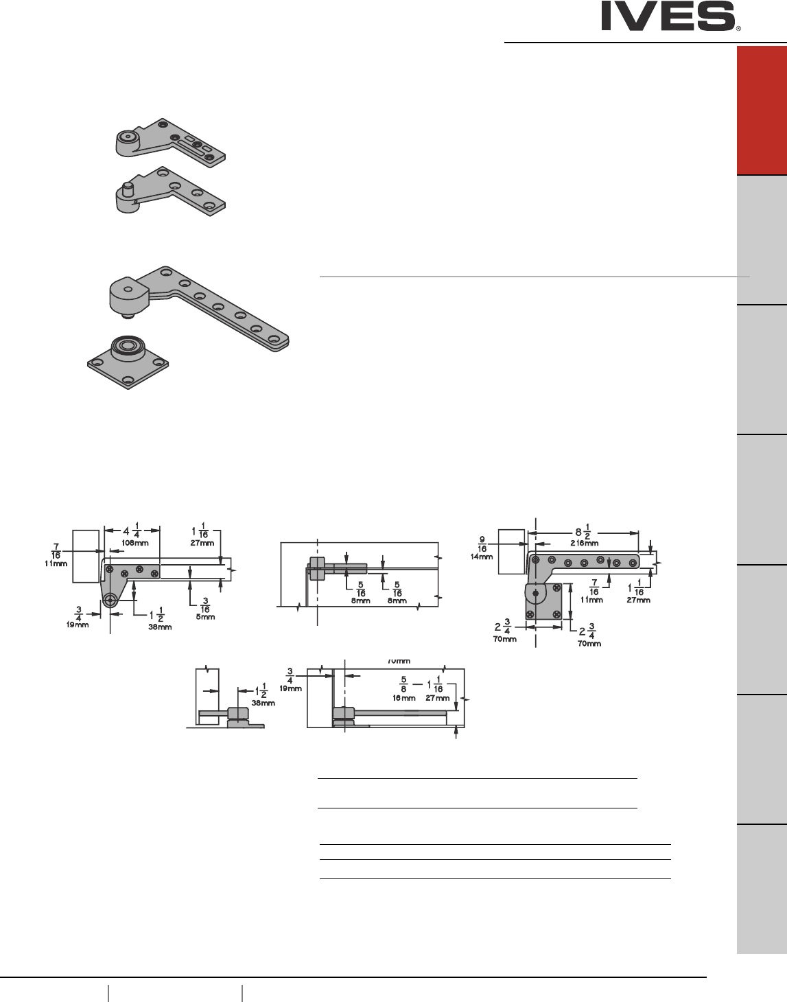
USA 1.877.671.7011 Canada 1.905.403.1800 www.ives.ingersollrand.com
Pivots
B
Pulls & Plates
A41
Hinges & Pivots
C
Flush Bolts & Coordinators
D
Latches, Catches & Bolts
E
Stops
F
Exterior Hardware
G
Miscellaneous Hardware
A41
Meets ANSI/BHMA A156.4 C07162
UL Listed 3 Hour Fire Doors
7244F 1-1/2" Offset Pivot - Heavy Duty
• Non-Handed
• Top, header mount
• Bottom, base mount
• Use with 1-3/4" minimum door thickness
• Maximum door load 400 pounds
• Vertical adjustment range 3/16", with positive locking
Optional 7244F-7245F Intermediate Pivot (handed) for each
additional 100 pounds or doors over 7'. See page A48.
Plated Finishes steel
US Number US3 US10 US32 US32D
BHMA Number 632 639 629 630
Painted Finishes steel
US Number SP4 SP10 SP28 SP313 SPBLK
BHMA Number 706 691 689 695 622
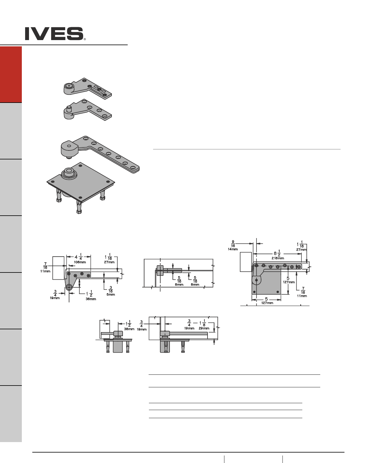
A42
USA 1.877.671.7011 Canada 1.905.403.1800 www.ives.ingersollrand.com
Pivots
B
Pulls & Plates
A42
Hinges & Pivots
C
Flush Bolts & Coordinators
D
Latches, Catches & Bolts
E
Stops
F
Exterior Hardware
G
Miscellaneous Hardware
Meets ANSI/BHMA A156.4 C07121
UL Listed 3 Hour Fire Doors
7245F 1-1/2" Offset Pivot - Heavy Duty
• Non-Handed
• Top, header mount
• Bottom, mortised cement case mount
• Use with 1-3/4" minimum door thickness, with 1/8" bevel in 2"
• Maximum door load 500 pounds
• Vertical adjustment range 3/16", with positive locking
Optional 7244F-7245F Intermediate Pivot (handed) for each
additional 100 pounds or doors over 7'. See page A48.
Plated Finishes steel
US Number US3 US4 US10 US10B US26 US26D
BHMA Number 632 639 612 613 625 626
Painted Finishes steel
US Number SP4 SP10 SP28 SP313 SPBLK
BHMA Number 706 691 689 695 622
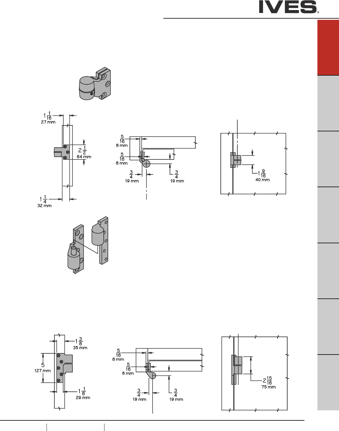
USA 1.877.671.7011 Canada 1.905.403.1800 www.ives.ingersollrand.com
Intermediate Pivots
B
Pulls & Plates
A43
Hinges & Pivots
C
Flush Bolts & Coordinators
D
Latches, Catches & Bolts
E
Stops
F
Exterior Hardware
G
Miscellaneous Hardware
A43
NFPA 80, Section 3-3.8 requires intermediate pivot on some fire door applications, consult
factory. Use for door heights over 7'0" and one every 2'6" or . Use for door weight over
the pivot set limit. One additional for every additional 100 pounds. Door thickness 1-3/4"
mimumum with 1/8" bevel in 2".
7212-7212V-7222 INT
• Use with 7212, 7212V or 7222 3/4 Offset Pivot
• Handed
• Vertical adjustment 3/16", include positive locking.
7215-7226-7227 INT
• Use with 7215, 7226 or 7227 3/4 Offset Pivot
• Handed
• Vertical adjustment 3/16", include positive locking.
7215F-7226F-7227F INT
• Use with 7215F, 7226F or 7227F 3/4 Offset Pivot
• Handed
• Vertical adjustment 3/16", include positive locking.
7215-7226-7227 INT:
UL listed 20 minute fire doors
Meets ANSI/BHMA A156.4 C07321
7215F-7226F-7227F INT:
UL listed 3 hour fire doors
Meets ANSI/BHMA A156.4 C07371
Meets ANSI/BHMA A156.4 C07382
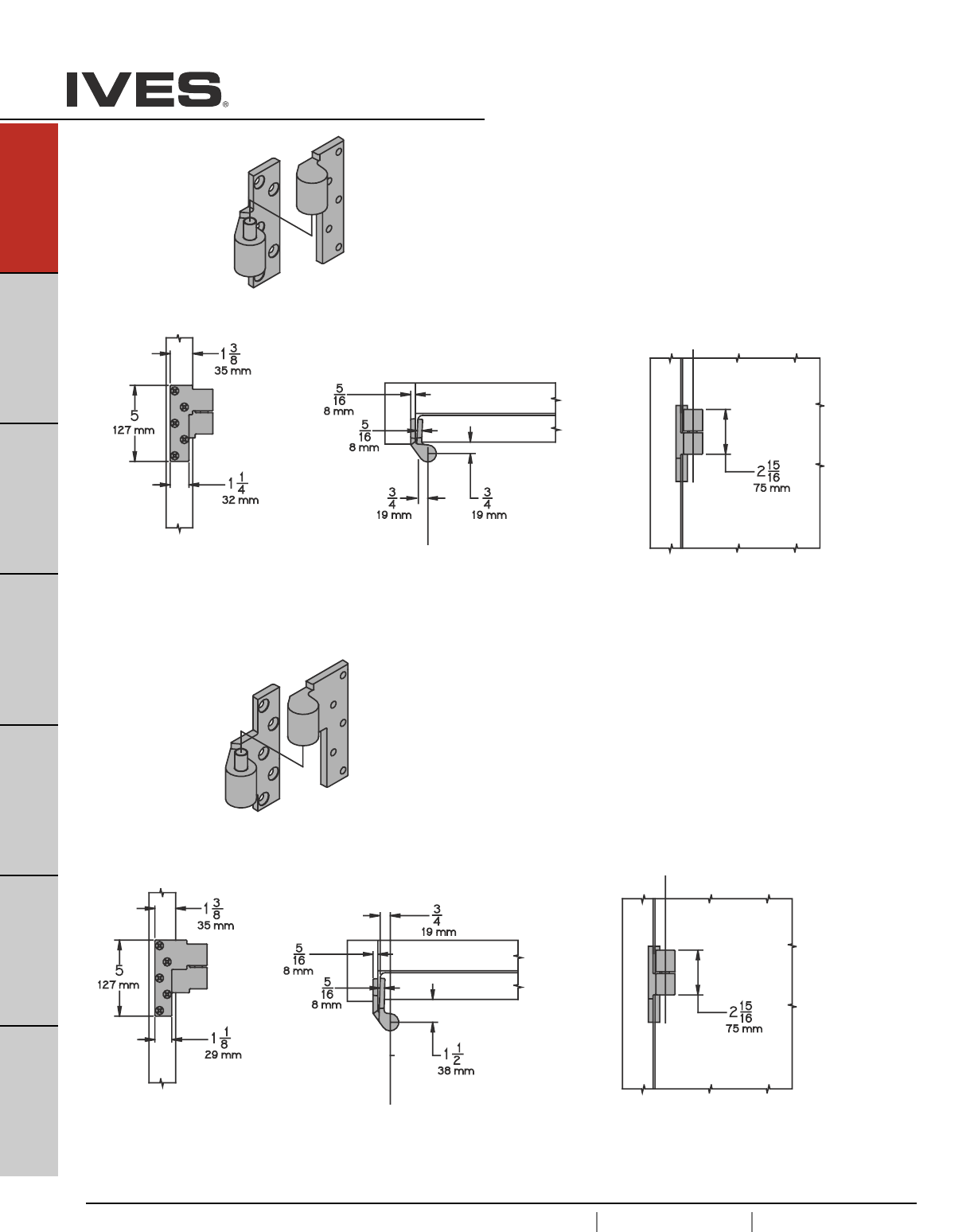
A44
USA 1.877.671.7011 Canada 1.905.403.1800 www.ives.ingersollrand.com
Intermediate Pivots
B
Pulls & Plates
A44
Hinges & Pivots
C
Flush Bolts & Coordinators
D
Latches, Catches & Bolts
E
Stops
F
Exterior Hardware
G
Miscellaneous Hardware
UL listed 3 hour fire doors
Meets ANSI/BHMA A156.4 C07311
UL listed 3 hour fire doors
Meets ANSI/BHMA A156.4 C07371
7230F-7237F INT
• Use with 7230F or 7237F 3/4 Offset Pivot
• Handed
• Vertical adjustment 3/16", include positive locking.
7244F-7245F
• Use with 7244F or 7245F 1-1/2" Offset Pivot
• Handed
• Vertical adjustment 3/16", include positive locking.
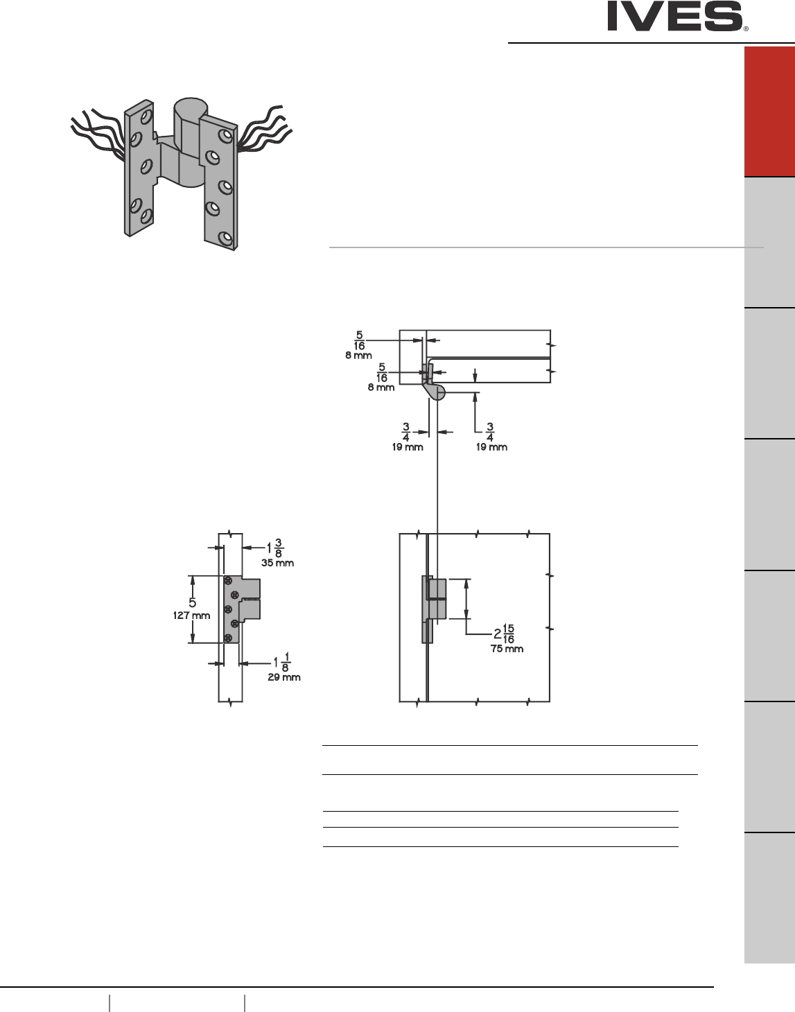
USA 1.877.671.7011 Canada 1.905.403.1800 www.ives.ingersollrand.com
Pivots
B
Pulls & Plates
A45
Hinges & Pivots
C
Flush Bolts & Coordinators
D
Latches, Catches & Bolts
E
Stops
F
Exterior Hardware
G
Miscellaneous Hardware
A45
7215PT-7226PT-7227PT Power Transfer Pivot
• Use with 7215, 7226 or 7227 3/4" Offset Pivots
• Four wires, 28 guage
• Optional 8 wire available
• Rated 50 VDC or VAC @ 3.5 amps. Continuous or
16 amps pulse, maximum pulse 400 milliseconds.
• Non-load bearing
• Use with 1-3/4" thick door mimimum, 1/8" bevel in 2".
Plate Finishes brass
US Number US3 US4 US10 US10B US26 US26D
BHMA Number 605 606 612 613 625 626
Painted Finishes brass
US Number SP4 SP10 SP28 SP313 SPBLK
BHMA Number 706 691 689 695 622
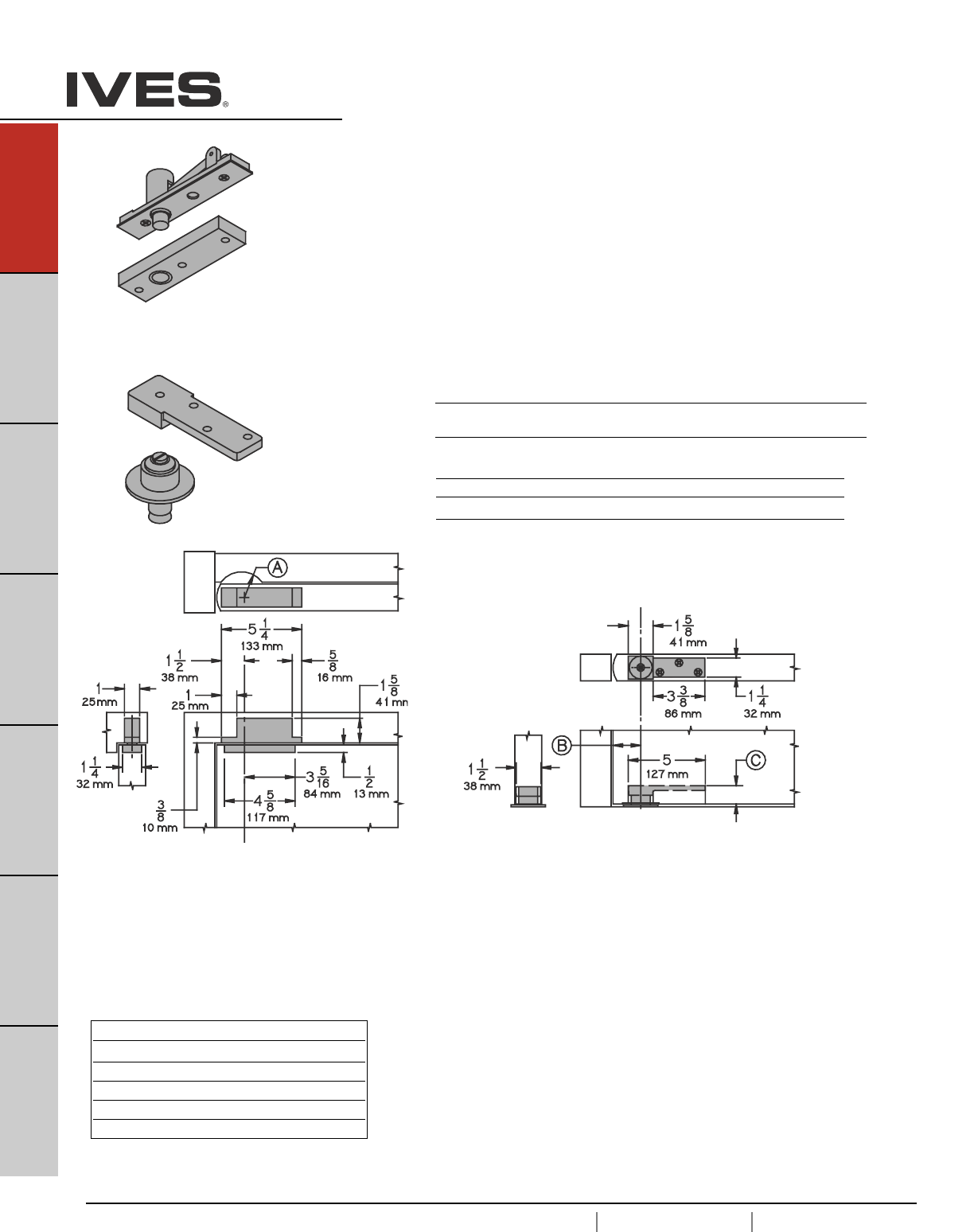
A46
USA 1.877.671.7011 Canada 1.905.403.1800 www.ives.ingersollrand.com
Pivots
B
Pulls & Plates
A46
Hinges & Pivots
C
Flush Bolts & Coordinators
D
Latches, Catches & Bolts
E
Stops
F
Exterior Hardware
G
Miscellaneous Hardware
Table D
Clearance Depth of Mortise
3/16" (5mm) 1-3/16" (30mm)
3/8" (10mm) 1" (25mm)
1/2" (13mm) 7/8" (22mm)
5/8" (16mm) 3/4" (19mm)
3/4" (19mm) 5/8" (16mm)
7253 Center Hung Pivot
• Non-Handed
• Top, header mount
• Bottom, base plate mount
• Easy installation tilt on bearing and bearing pin.
• Use with 1-3/4" minimum door thickness.
• Adjustable floor to door clearance 3/16" to 3/4".
• Maximum door load 300 pounds
• Vertical adjustment range 3/16", with positive locking
• Radius Stop (A) to clear heel of door edge.
• Pivot distance (B) 1-3/4" (44mm) mimumum from jamb to centerline of pivot pin. Radius heel
edge of door, 1-5/8" (41mm) mimumum recommended.
• Clearance from bottom edge of door to floor mounting surface is adjustable from 3/16" (5mm)
to 3/4" (19mm) by varing the depth of the mortise (C ) in the bottom of the door, refer to
Chart D. Consult factory when clearance is over 3/4" (19mm).
Plated Finishes brass
US Number US3 US4 US10 US10B US26 US26D
BHMA Number 605 606 612 613 625 626
Painted Finishes brass
US Number SP4 SP10 SP28 SP313 SPBLK
BHMA Number 706 691 689 695 622
Meets ANSI/BHMA A156.4 C07032
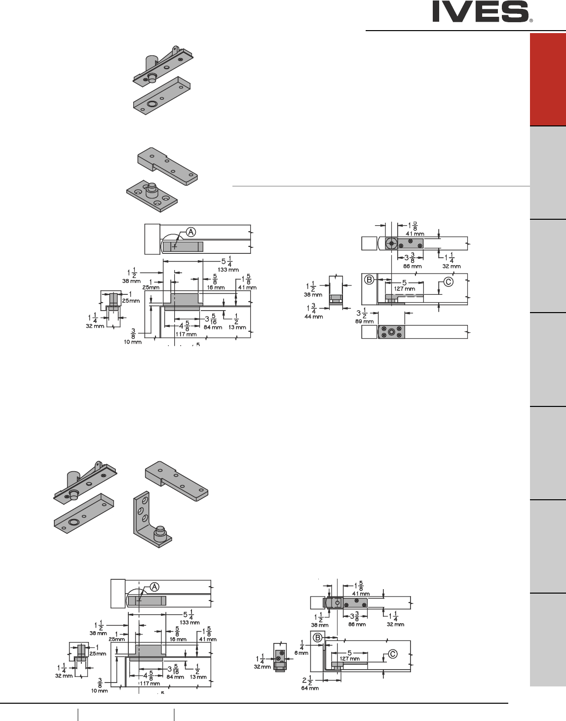
7255 Center Hung Pivot
• Non-Handed
• Top, header mount
• Bottom, base plate mount
• Easy installation tilt on bearing and bearing pin.
• Use with 1-3/4" minimum door thickness.
• Adjustable floor to door clearance 3/16" to 3/4", consultant
factory if greater than 3/4"..
• Maximum door load 500 pounds
• Vertical adjustment range 3/16", with positive locking
7255J Center Hung Pivot
• Non-Handed
• Top, header mount
• Bottom, jamb mount
• Easy installation tilt on bearing and bearing pin.
• Use with 1-3/4" minimum door thickness.
• Adjustable floor to door clearance 3/16" to 3/4", consult factory
if greater than 3/4".
• Maximum door load 500 pounds
• Vertical adjustment range 3/16", with positive locking
• Radius Stop (A) to clear heel of door edge.
• Pivot distance (B) 1-3/4" (44mm) mimumum from jamb to centerline of pivot pin. Radius
heel edge of door, 1-5/8" (41mm) mimumum recommended.
• Clearance from bottom edge of door to floor mounting surface is adjustable from 3/16"
(5mm) to 3/4" (19mm) by varing the depth of the mortise (C ) in the bottom of the door,
refer to Chart D. Consult factory when clearance is over 3/4" (19mm).
Meets ANSI/BHMA A156.4 C07032
Meets ANSI/BHMA A156.4 C07042
USA 1.877.671.7011 Canada 1.905.403.1800 www.ives.ingersollrand.com
Pivots
B
Pulls & Plates
A47
Hinges & Pivots
C
Flush Bolts & Coordinators
D
Latches, Catches & Bolts
E
Stops
F
Exterior Hardware
G
Miscellaneous Hardware
A47
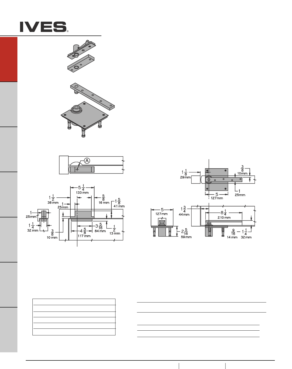
A48
USA 1.877.671.7011 Canada 1.905.403.1800 www.ives.ingersollrand.com
Pivots
B
Pulls & Plates
A48
Hinges & Pivots
C
Flush Bolts & Coordinators
D
Latches, Catches & Bolts
E
Stops
F
Exterior Hardware
G
Miscellaneous Hardware
Table D
Clearance Depth of Mortise
3/16" (5mm) 1-3/16" (30mm)
3/8" (10mm) 1" (25mm)
1/2" (13mm) 7/8" (22mm)
5/8" (16mm) 3/4" (19mm)
3/4" (19mm) 5/8" (16mm)
Meets ANSI/BHMA A156.4 C07021
7256 Center Hung Pivot
• Non-Handed
• Top, header mount
• Bottom, base frame mount
• Easy installation tilt on bearing and bearing pin.
• Use with 1-3/4" minimum door thickness.
• Adjustable floor to door clearance 3/16" to 3/4", consult factory
if greater than 3/4".
• Maximum door load 600 pounds
• Vertical adjustment range 3/16", with positive locking
• Radius Stop (A) to clear heel of door edge.
• Pivot distance (B) 1-3/4" (44mm) mimumum from jamb to centerline of pivot pin. Radius heel
edge of door, 1-5/8" (41mm) mimumum recommended.
• Clearance from bottom edge of door to floor mounting surface is adjustable from 3/16" (5mm)
to 3/4" (19mm) by varing the depth of the mortise (C ) in the bottom of the door,
refer to Chart D. Consult factory when clearance is over 3/4" (19mm).
Plated Finishes brass
US Number US3 US4 US10 US10B US26 US26D
BHMA Number 605 606 612 613 625 626
Painted Finishes brass
US Number SP4 SP10 SP28 SP313 SPBLK
BHMA Number 706 691 689 695 622
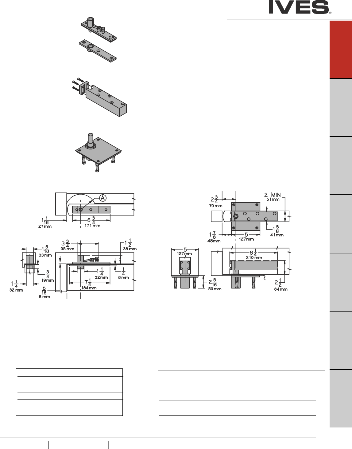
USA 1.877.671.7011 Canada 1.905.403.1800 www.ives.ingersollrand.com
Pivots
B
Pulls & Plates
A49
Hinges & Pivots
C
Flush Bolts & Coordinators
D
Latches, Catches & Bolts
E
Stops
F
Exterior Hardware
G
Miscellaneous Hardware
A49
Table D
Clearance Depth of Mortise
3/16" (5mm) 1-3/16" (30mm)
3/8" (10mm) 1" (25mm)
1/2" (13mm) 7/8" (22mm)
5/8" (16mm) 3/4" (19mm)
3/4" (19mm) 5/8" (16mm)
Meets ANSI/BHMA A156.4 C07011
• Radius Stop (A) to clear heel of door edge.
• Pivot distance (B) 1-3/4" (44mm) mimumum from jamb to centerline of pivot pin. Radius heel
edge of door, 1-5/8" (41mm) mimumum recommended.
• Clearance from bottom edge of door to floor mounting surface is adjustable from 3/16" (5mm) to
3/4" (19mm) by varing the depth of the mortise (C ) in the bottom of the door, refer to Chart D.
Consult factory when clearance is over 3/4" (19mm).
7259 Center Hung Pivot
• Non-Handed
•Top, header mount
• Bottom, base frame mount
• Easy installation tilt on bearing and bearing pin.
• Use with 2" minimum door thickness.
• Adjustable floor to door clearance 3/16" to 3/4", consult factory
if greater than 3/4".
• Maximum door load 1,000 pounds
• Vertical adjustment range 3/16", with positive locking
Plated Finishes brass
US Number US3 US4 US10 US10B US26 US26D
BHMA Number 605 606 612 613 625 626
Painted Finishes brass
US Number SP4 SP10 SP28 SP313 SPBLK
BHMA Number 706 691 689 695 622
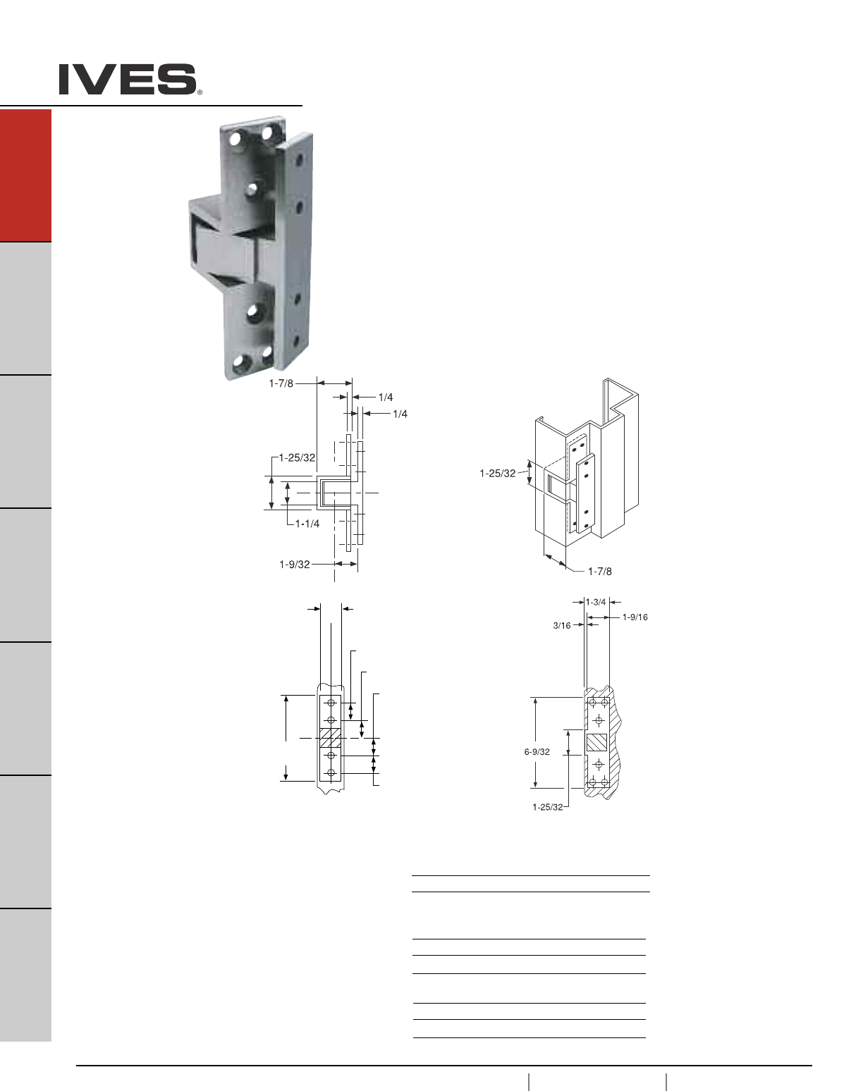
A50
USA 1.877.671.7011 Canada 1.905.403.1800 www.ives.ingersollrand.com
Pivots
B
Pulls & Plates
A50
Hinges & Pivots
C
Flush Bolts & Coordinators
D
Latches, Catches & Bolts
E
Stops
F
Exterior Hardware
G
Miscellaneous Hardware
UL Listed 3 hour fire doors
or 20 minute wood fire doors
Meets ANSI/BHMA A156.4 C07611
91105F, 91105F-PT Pocket Pivot/Hinge
•Non-handed
• All stainless steel construction.
• Allows door to open a full 90 (* degree mark)
• Full mortise
• 90 pound load bearing
• Use two for doors up to 7'0" and over 7'0" use three.
• PT, Power Transfer version has four 28 guage wires. Rated 50 VOC
or VAC @ 3.5 amps. Continuous or 16 amps pulse.
Maximum pulse 400 milliseconds.
91105F Pocket Pivot
Pocket
Pivot
Cutout
1-3/8
1-1/8
1-1/8
5-17/32
1-9/64
1-9/64
C
L
of Door
Door
Portion
Jamb
Portion
Plated Finishes steel
US Number US3 US10 US10B
BHMA Number 632 639 640
Finishes stainless steel
US Number US32 US32D
BHMA Number 629 630
Painted Finishes steel
US Number USP SP313
BHMA Number 600 695
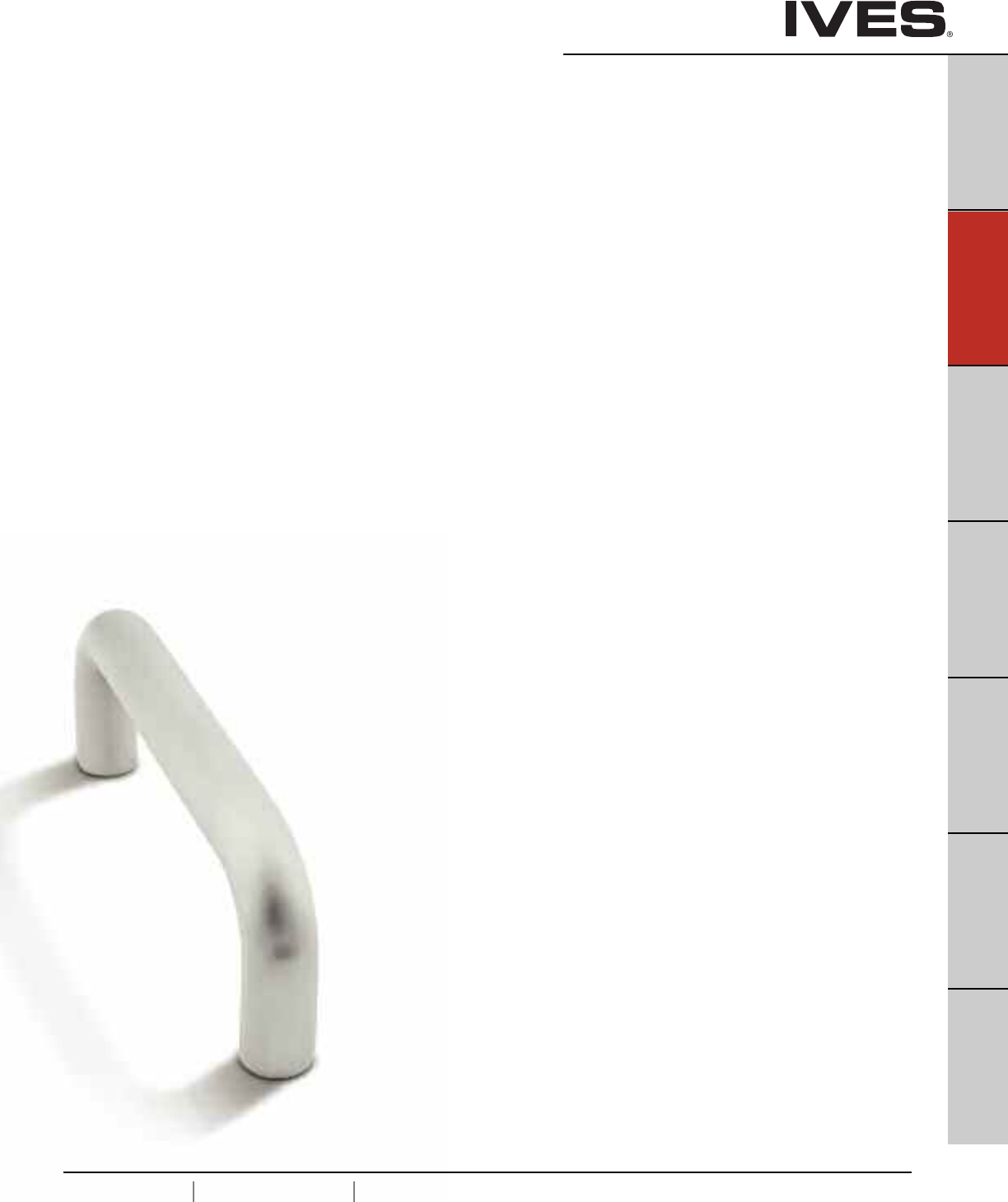
B1
USA 1.877.671.7011 Canada 1.905.403.1800 www.ives.ingersollrand.com
Pulls & Plates
B1
Pulls & Plates
A
Hinges & Pivots
C
Flush Bolts & Coordinators
D
Latches, Catches & Bolts
E
Stops
F
Exterior Hardware
G
Miscellaneous Hardware
Table Of Contents
Pulls, Plates and Trim
Pulls page
8102 Door Pull . . . . . . . . . . . . . . . . . . . . . . . . . . . . . . . . . . . . . . . . . . . . . .B2
8103 Door Pull . . . . . . . . . . . . . . . . . . . . . . . . . . . . . . . . . . . . . . . . . . . . . .B2
8103EZ Door Pull . . . . . . . . . . . . . . . . . . . . . . . . . . . . . . . . . . . . . . . . . . . .B3
8105 Door Pull . . . . . . . . . . . . . . . . . . . . . . . . . . . . . . . . . . . . . . . . . . . . . .B3
8111-5 Door Pull . . . . . . . . . . . . . . . . . . . . . . . . . . . . . . . . . . . . . . . . . . . .B4
8112-5 Door Pull . . . . . . . . . . . . . . . . . . . . . . . . . . . . . . . . . . . . . . . . . . . .B4
8121 Door Pull . . . . . . . . . . . . . . . . . . . . . . . . . . . . . . . . . . . . . . . . . . . . . .B5
8190 Offset Door Pull . . . . . . . . . . . . . . . . . . . . . . . . . . . . . . . . . . . . . . . . .B5
Push and Pull Plates
8200 Push Plate . . . . . . . . . . . . . . . . . . . . . . . . . . . . . . . . . . . . . . . . . . . . .B6
8300 Pull Plate (less pull) . . . . . . . . . . . . . . . . . . . . . . . . . . . . . . . . . . . . . .B6
8302 Pull Plate . . . . . . . . . . . . . . . . . . . . . . . . . . . . . . . . . . . . . . . . . . . . . .B7
8303 Pull Plate . . . . . . . . . . . . . . . . . . . . . . . . . . . . . . . . . . . . . . . . . . . . . .B7
8305 Pull Plate (with 8105) . . . . . . . . . . . . . . . . . . . . . . . . . . . . . . . . . . . .B7
8311 Pull Plate (with 8111-5) . . . . . . . . . . . . . . . . . . . . . . . . . . . . . . . . . . .B8
Push Bars
9100 Pushbar . . . . . . . . . . . . . . . . . . . . . . . . . . . . . . . . . . . . . . . . . . . . . . .B8
9103EZ Pushber & Pull . . . . . . . . . . . . . . . . . . . . . . . . . . . . . . . . . . . . . . . .B9
9190 Pushbar & Pull . . . . . . . . . . . . . . . . . . . . . . . . . . . . . . . . . . . . . . . . . .B9
Vandal Resistant Trim
VR810-DT, VR814DT Vandal Resistant Trim . . . . . . . . . . . . . . . . . . . . . . .B10
VR810-NL, VR814-NL Vandal Resistant Trim . . . . . . . . . . . . . . . . . . . . . .B10
VR900, VR904 Vandual Resistant Trim . . . . . . . . . . . . . . . . . . . . . . . . . . .B11
VR900LLP, VR904LLP Vandual Resistant Trim . . . . . . . . . . . . . . . . . . . . . .B11
VR910-DT, VR914-DT Vandual Resistant Trim . . . . . . . . . . . . . . . . . . . . . .B12
VR910-NL, VR914-NL Vandual Resistant Trim . . . . . . . . . . . . . . . . . . . . .B12
VR910M-DT, VR914M-DT Vandual Resistant trim . . . . . . . . . . . . . . . . . . .B12
VR910M-NL, VR914M-NL Vandual Resistant Trim . . . . . . . . . . . . . . . . . .B12
Protection Plates
8400 Protection Plate . . . . . . . . . . . . . . . . . . . . . . . . . . . . . . . . . . . . .B13-14
8402 Protection Plate (UL) . . . . . . . . . . . . . . . . . . . . . . . . . . . . . . . . .B13-14
Mounting Detail
Special Mounting Detail . . . . . . . . . . . . . . . . . . . . . . . . . . . . . . . . . . . .B15-17
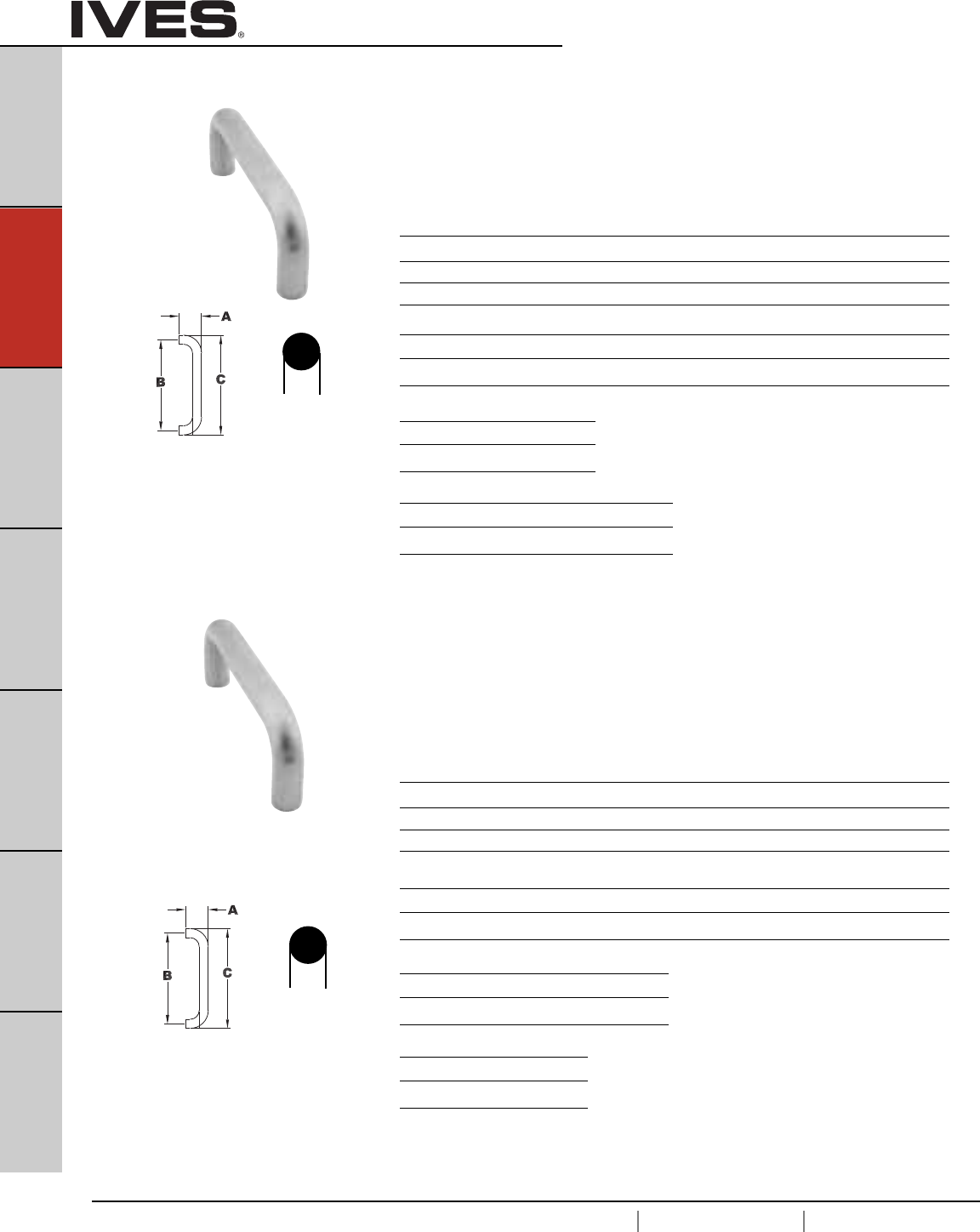
B2
USA 1.877.671.7011 Canada 1.905.403.1800 www.ives.ingersollrand.com
Architectural Door Trim
B2
Pulls & Plates
A
Hinges & Pivots
C
Flush Bolts & Coordinators
D
Latches, Catches & Bolts
E
Stops
F
Exterior Hardware
G
Miscellaneous Hardware
Projection Center to Center Overall Length
Product No. “A” Clearance “B” “C”
8102-6 2-1/4" 1-1/2" 6" 6-3/4"
8102-8 2-1/4" 1-1/2" 8" 8-3/4"
8102-0 2-1/4" 1-1/2" 10" 10-3/4"
Available Sizes
8", 10", 12"
Projection Center to Center Overall Length
Product No. “A” Clearance “B” “C”
8103-8 2-1/2" 1-1/2" 8" 9"
8103-0 2-1/2" 1-1/2" 10" 11"
8103-2 2-1/2" 1-1/2" 12" 13"
Finishes brass
US Number US3 US4 US10 US10B US15 US26 US26D*
BHMA 605 606 612 613 619 625 626
Finishes stainless steel
US Number US32D*
BHMA 630
Finishes aluminum
US Number US28
BHMA 628
Finishes brass
US Number US3 US4 US10 US10B US15 US26 US26D*
BHMA 605 606 612 613 619 625 626
Finishes stainless steel
US Number US32 US32D*
BHMA 629 630
Finishes aluminum
US Number US28
BHMA 628
8102 Door Pull - 3/4" Round
Available mounting – standard, F, H-I-L, orJ see pages B15 and B16
8103 Door Pull - 1" Round
Available mounting – standard, F, H-I-L, or J see pages B15 and B16
Available Sizes
6", 8", 10"
* Available with Antimicrobial Coating, use suffix AM
* Available with Antimicrobial Coating, use suffix AM
3/4”
ROUND
1”
ROUND
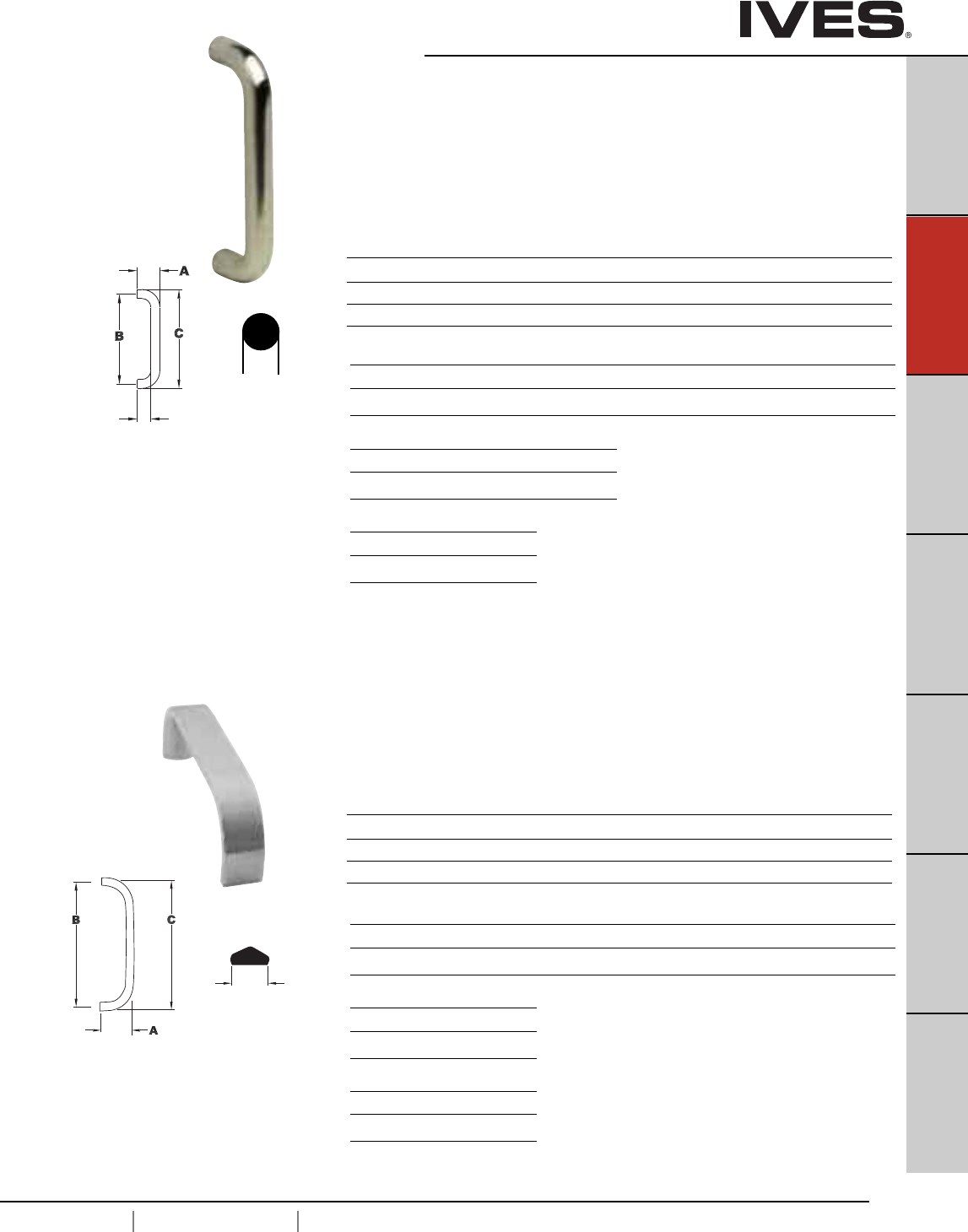
B3
USA 1.877.671.7011 Canada 1.905.403.1800 www.ives.ingersollrand.com
Architectural Door Trim
B3
Pulls & Plates
A
Hinges & Pivots
C
Flush Bolts & Coordinators
D
Latches, Catches & Bolts
E
Stops
F
Exterior Hardware
G
Miscellaneous Hardware
8103EZ Door Pull -1” Round
Large 2-1/2" Clearance for the Accessibility Applications
Available mounting – standard, M, O, H-I-L, J see pages B15 and B17
Available Sizes
8", 10", 12"
Projection Center to Center Overall Length
Product No. “A” Clearance “B” “C”
8103EZ 3-1/2" 2-1/2" 8" 9"
8103EZ 3-1/2" 2-1/2" 10" 11"
8103EZ 3-1/2" 2-1/2" 12" 13"
8105 Door Pull -1” Flattened
Available mounting – standard or F see page B15
Available Sizes
6", 8", 10"
Projection Center to Center Overall Length
Product No. “A” “B” “C”
8105-6 2" 6" 6-1/2"
8105-8 2" 8" 8-1/2"
8105-0 2" 10" 10-1/2"
1”
FLATTED
1/2 ROUND
Finishes brass
US Number US3 US4 US10 US10B US15 US26 US26D*
BHMA 605 606 612 613 619 625 626
Finishes stainless steel
US Number US32 US32D*
BHMA 629 630
Finishes aluminum
US Number US28
BHMA 628
Finishes brass
US Number US3 US4 US10 US10B US15 US26 US26D*
BHMA 605 606 612 613 619 625 626
Finishes stainless steel
US Number US32D*
BHMA 630
Finishes aluminum
US Number US28
BHMA 628
* Available with Antimicrobial Coating, use suffix AM
* Available with Antimicrobial Coating, use suffix AM
1”
ROUND
2-1/2”
CLEARANCE
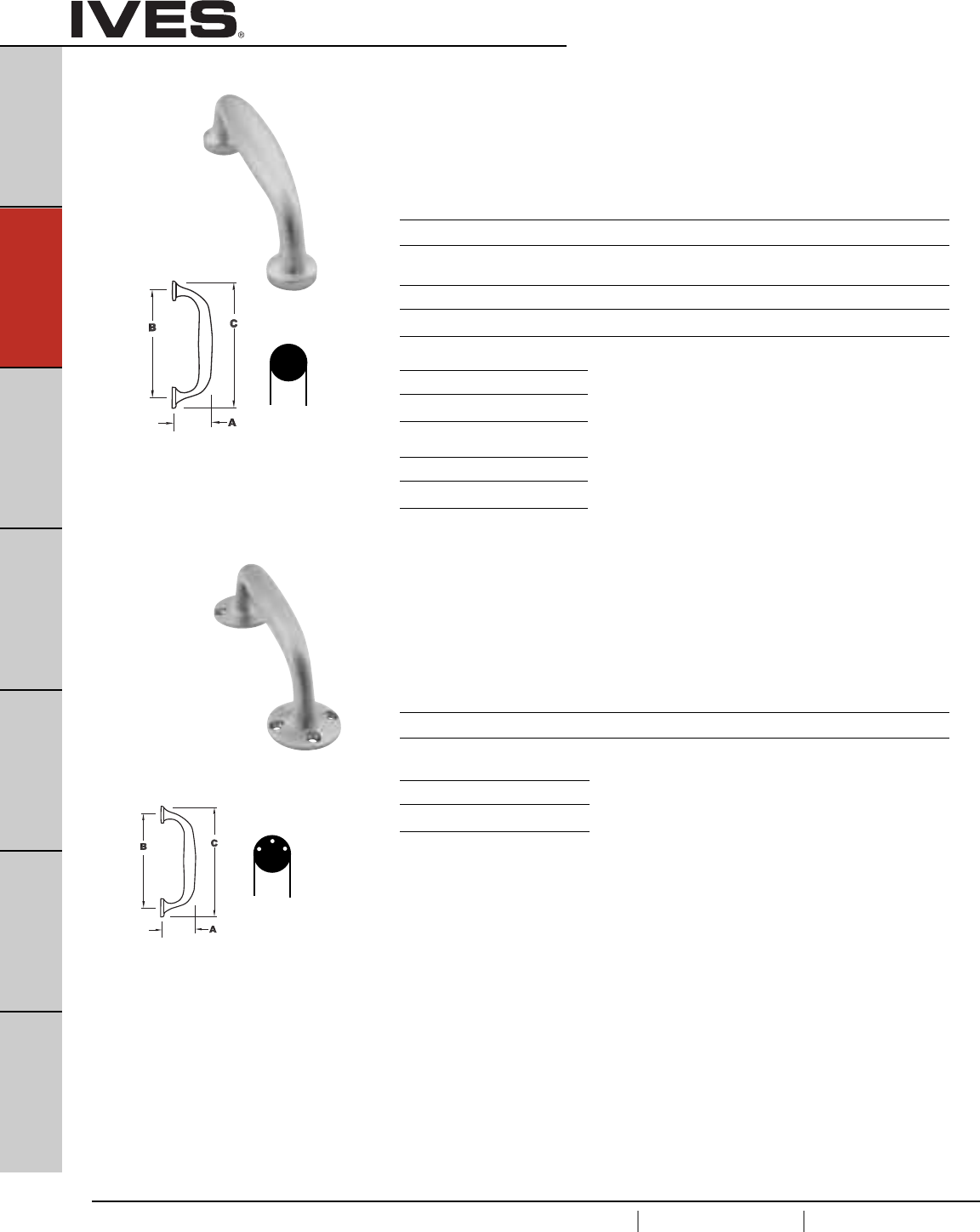
B4
USA 1.877.671.7011 Canada 1.905.403.1800 www.ives.ingersollrand.com
Architectural Door Trim
B4
Pulls & Plates
A
Hinges & Pivots
C
Flush Bolts & Coordinators
D
Latches, Catches & Bolts
E
Stops
F
Exterior Hardware
G
Miscellaneous Hardware
8111-5 Door Pull
Available mounting – standard see page B15
Size
5-1/4"
Projection Center to Center Overall Length
Product No. “A” “B” “C”
8111-5 1-13/16" 5-1/4" 6-1/4"
Finishes brass
US Number US3 US4 US10 US10B US15 US26 US26D*
BHMA 605 606 612 613 619 625 626
Finishes stainless steel
US Number US32D*
BHMA 630
Finishes aluminum
US Number US28
BHMA 628
8112-5 Door Pull
Standard sheet metal screws for surface mounting
Size
5-1/4"
Projection Center to Center Overall Length
Product No. “A” “B” “C”
8112-5 2-13/16" 5-5/8" 7-1/2"
Finishes brass
US Number US26D*
BHMA 626
* Available with Antimicrobial Coating, use suffix AM
* Available with Antimicrobial Coating, use suffix AM
1”
ROUND
BASE
1-7/8”
SURFACE
MOUNTED
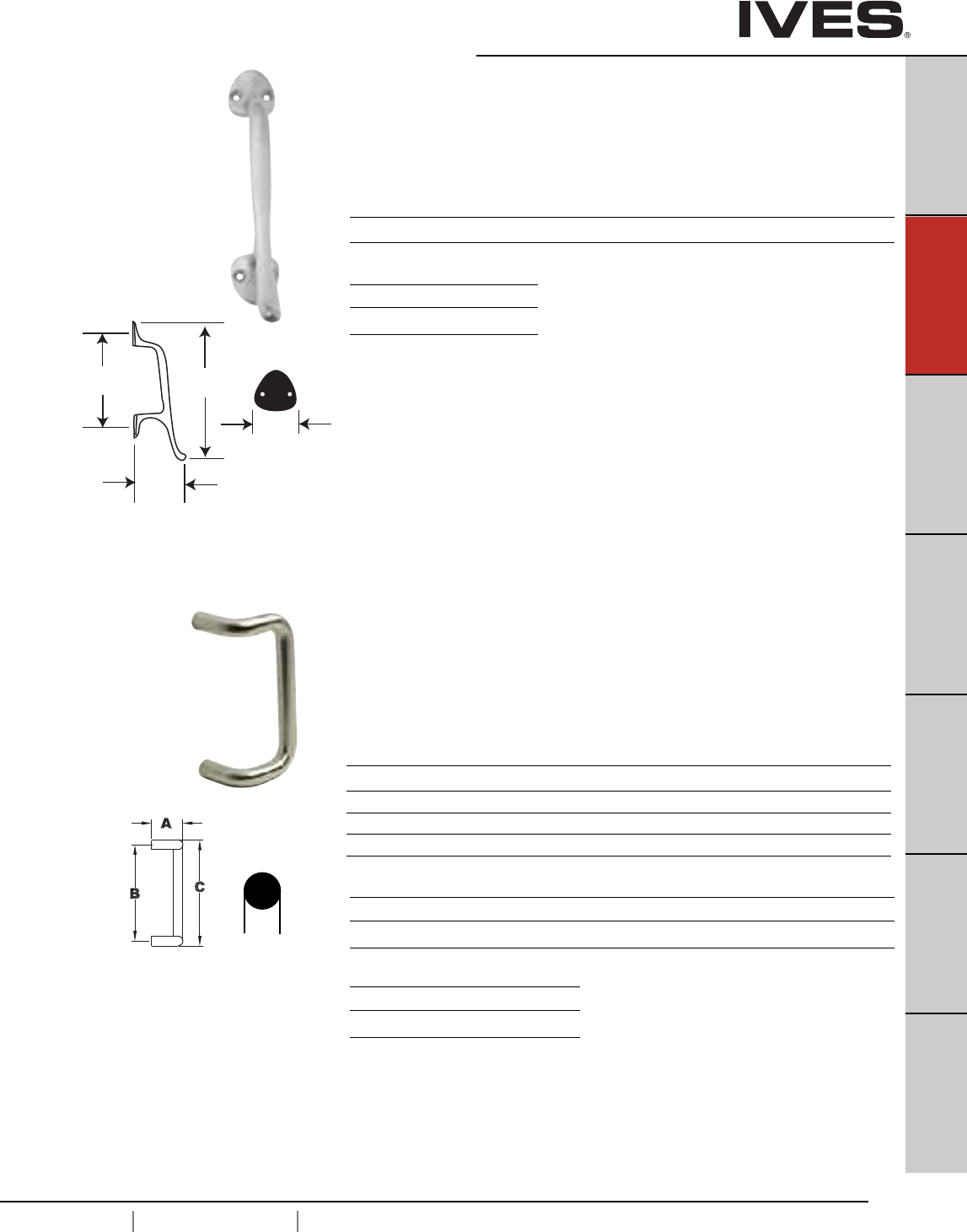
B5
USA 1.877.671.7011 Canada 1.905.403.1800 www.ives.ingersollrand.com
Architectural Door
B5
Pulls & Plates
A
Hinges & Pivots
C
Flush Bolts & Coordinators
D
Latches, Catches & Bolts
E
Stops
F
Exterior Hardware
G
Miscellaneous Hardware
8121 Door Pull
Available mounting – K see page B16
Size
5-3/4"
Projection Center to Center Overall Length
Product No. “A” “B” “C”
8121-5 3-1/2" 5-3/4" 8-3/4"
C
A
1-1/2”
HOSPITAL
B
8190 90° Offset Door Pull
Available mounting – standard H-I-L,M, N or O see page B15 and B17
Available Sizes
8", 10", 12", 18"
Projection Center to Center Overall Length
Product No. “A” Clearance “B” “C”
8190-8 3-1/4" 2-1/4" 8" 9"
8190-0 3-1/4" 2-1/4" 10" 11"
8190-2 3-1/4" 2-1/4" 12" 13"
8190-18 3-1/4" 2-1/4" 18" 19"
Finishes brass
US Number US3 US4 US10 US10B US15 US26 US26D*
BHMA 605 606 612 613 619 625 626
Finishes stainless steel
US Number US32 US32D*
BHMA 629 630
Finishes brass
US Number US26D*
BHMA 626
* Available with Antimicrobial Coating, use suffix AM
* Available with Antimicrobial Coating, use suffix AM
1”
ROUND
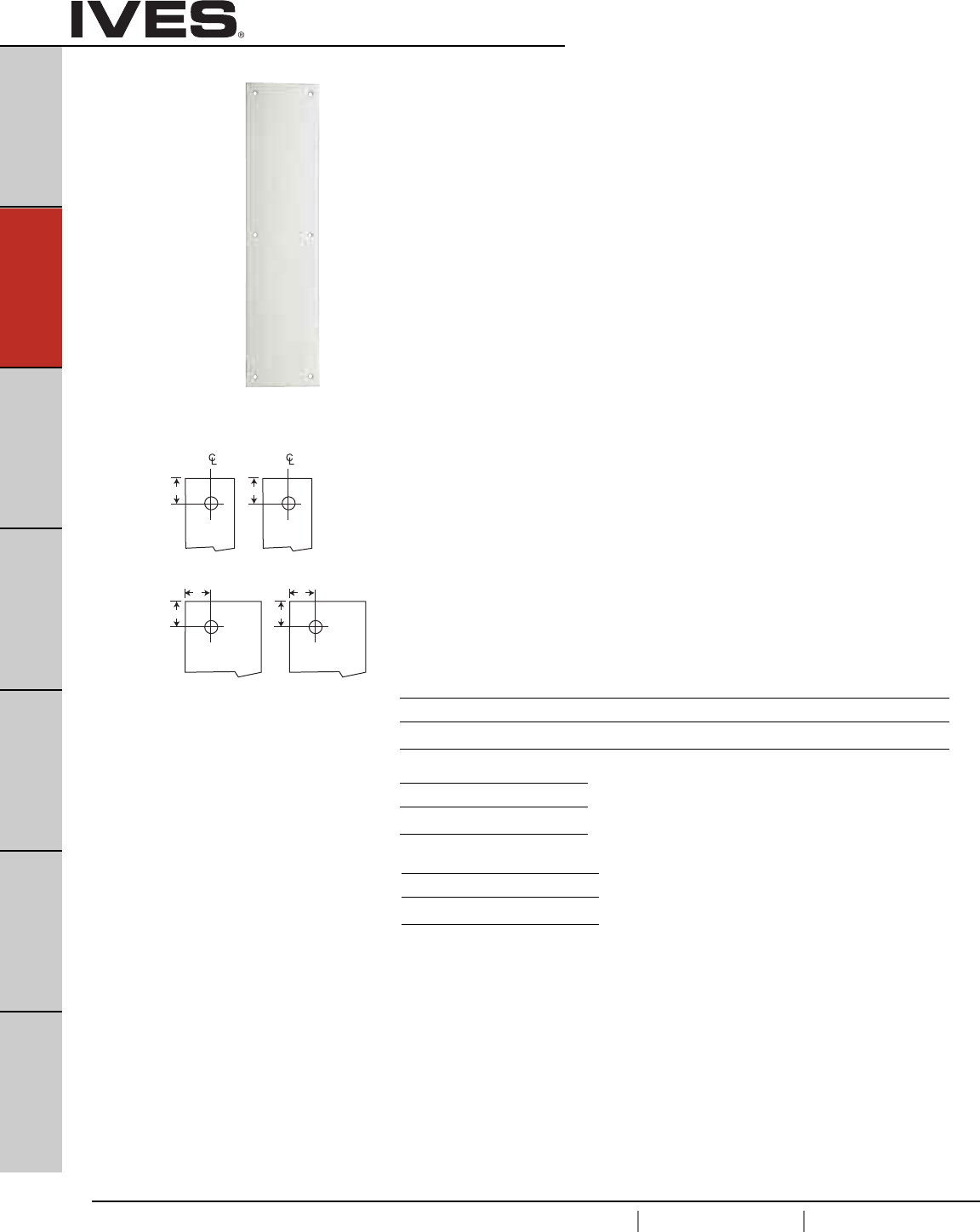
B6
USA 1.877.671.7011 Canada 1.905.403.1800 www.ives.ingersollrand.com
Architectural Door Trim
B6
Pulls & Plates
A
Hinges & Pivots
C
Flush Bolts & Coordinators
D
Latches, Catches & Bolts
E
Stops
F
Exterior Hardware
G
Miscellaneous Hardware
Plates Cut for Cylinder or Thumbturns
Plates are available with cutout for cylinder or thumbturn; standard cutout is 2” from
top and centered on plates up to 4” wide. For plates wider than 4” cutout is located
2” from outer edge, specify LH or RH. When pull location interferes with standard
cutout location a detail drawing should be furnished with the order.
Standard cutout is 1-1/4” for cylinder and 3/8” for thumbturn.
Specify CFC for cutout for cylinder or CFT for cutout for thumbturn.
8200 Push Plate
8300 Pull Plate, Prep for Pull (less pull)
Available Sizes
3" x 12"
3.5" x 15"
4" x 16"
6" x 16"
8" x 16"
Special sizes are available. Consult factory.
2”
2”
2”
CFC
2”
CFT
CFC
2”
2”
CFT
Finishes brass
US Number US3 US4 US10 US10B US15 US26 US26D*
BHMA 605 606 612 613 619 625 626
Finishes stainless steel
US Number US32D*
BHMA 630
Finishes aluminum
US Number US28
BHMA 628
* Available with Antimicrobial Coating, use suffix AM
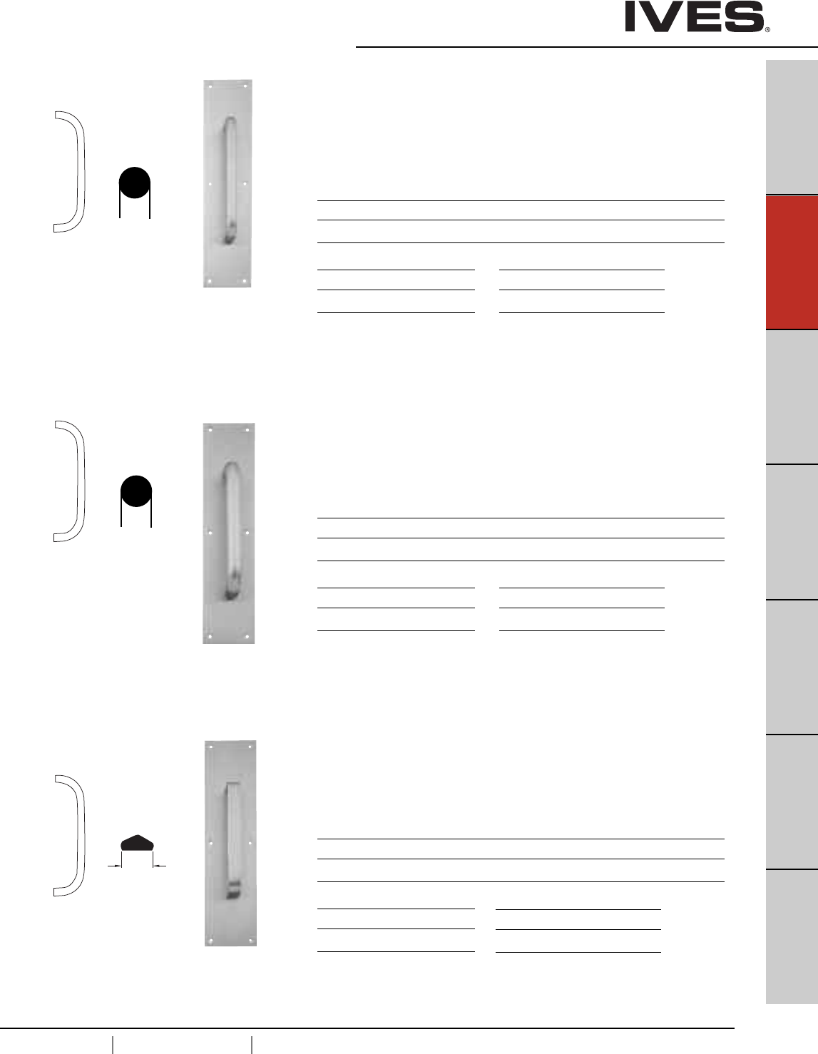
B7
USA 1.877.671.7011 Canada 1.905.403.1800 www.ives.ingersollrand.com
Architectural Door Trim
B7
Pulls & Plates
A
Hinges & Pivots
C
Flush Bolts & Coordinators
D
Latches, Catches & Bolts
E
Stops
F
Exterior Hardware
G
Miscellaneous Hardware
8302 Pull plate
Available mounting – Standard, F, G, H-I-L, or J see pages B15 and B16
8300 Plate 8102 Pull
3-1/2" x 15" 6" centers
4" x 16" 8" centers
6" x 16" 10" centers
8303 Pull plate
Available mounting – Standard, F, G, H-I-L, or J see pages B15 and B16
8300 Plate 8103 Pull
3-1/2" x 15" 8" centers
4" x 16" 10" centers
6" x 16" 7" centers
8305 Pull plate
Available mounting – Standard or F see page B15
8300 Plate 8105 Pull
3-1/2" x 15" 6" centers
4" x 16" 8" centers
6" x 16" 10" centers
Finishes brass
US Number US3 US4 US10 US10B US26 US26D*
BHMA 605 606 612 613 625 626
Finishes stainless steel
US Number US32D*
BHMA 630
Finishes aluminum
US Number US28
BHMA 628
Finishes brass
US Number US3 US4 US10 US10B US26 US26D*
BHMA 605 606 612 613 625 626
Finishes stainless steel
US Number US32D*
BHMA 630
Finishes aluminum
US Number US28
BHMA 628
Finishes brass
US Number US3 US4 US10 US10B US26 US26D
BHMA 605 606 612 613 625 626
Finishes stainless steel
US Number US32D
BHMA 630
Finishes aluminum
US Number US28
BHMA 628
* Available with Antimicrobial Coating, use suffix AM
* Available with Antimicrobial Coating, use suffix AM
* Available with Antimicrobial Coating, use suffix AM
3/4”
ROUND
1”
ROUND
1”
FLATTED
1/2 ROUND
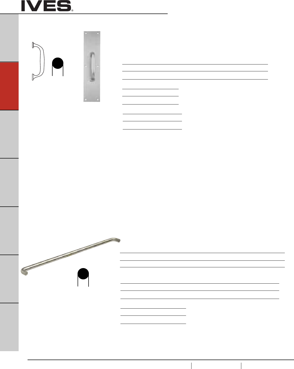
B8
USA 1.877.671.7011 Canada 1.905.403.1800 www.ives.ingersollrand.com
Architectural Door Trim
B8
Pulls & Plates
A
Hinges & Pivots
C
Flush Bolts & Coordinators
D
Latches, Catches & Bolts
E
Stops
F
Exterior Hardware
G
Miscellaneous Hardware
9100 Series Door Push Bars and Pulls
• Available in brass, stainless steel or aluminum.
• Standard fasteners furnished for 1-3/4” thick doors. Specify door
thick if other than standard.
• Special lengths are available, contact customer service.
See page B17 for special mounting requirements.
Caution – the length of the pushbar should not interfere with the door jamb or
cause a pinch point.
Product No. Projection Clearance Center to Center Overall Length
9100-28 2-1/2" 1-1/2" 28" 29"
9100-33 2-1/2" 1-1/2" 33" 34"
Finishes brass
US Number US3 US4 US10 US10B US15 US26 US26D*
BHMA 605 606 612 613 619 625 626
Finishes stainless steel
US Number US32 US32D*
BHMA 629 630
9100 Push Bar
Available mounting – NO or NS see page B17
8311 Pull plate
Available mounting – Standard or F see page B15
8300 Plate 8111-5 Pull
3-1/2" x 15" 5-1/8" centers
4" x 16"
6" x 16"
Finishes brass
US Number US3 US4 US10 US10B US26 US26D*
BHMA 605 606 612 613 625 626
Finishes stainless steel
US Number US32D*
BHMA 630
Finishes aluminum
US Number US28
BHMA 628
* Available with Antimicrobial Coating, use suffix AM
* Available with Antimicrobial Coating, use suffix AM
Special lengths available, consult factory
1”
ROUND
BASE
1”
ROUND
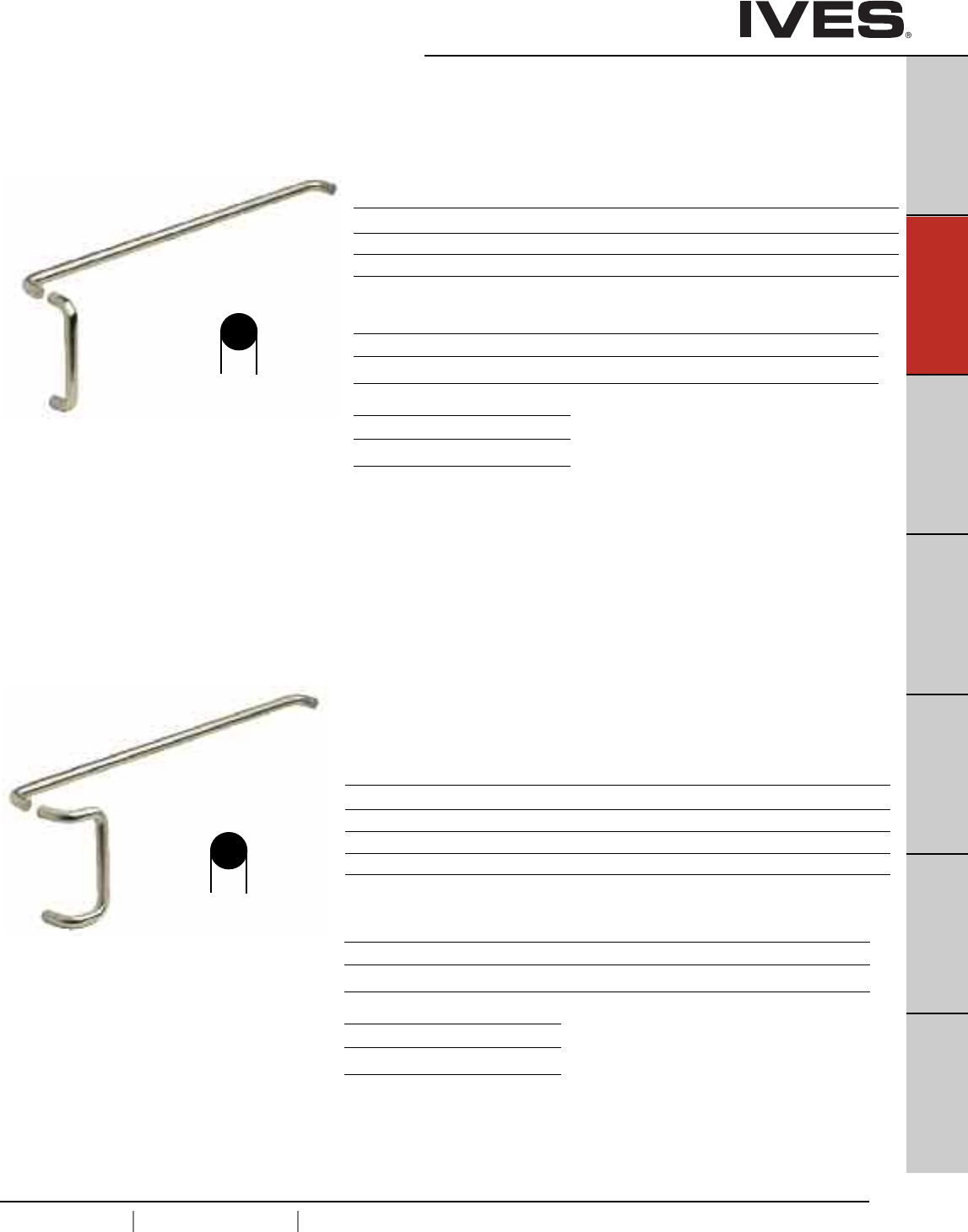
B9
USA 1.877.671.7011 Canada 1.905.403.1800 www.ives.ingersollrand.com
Architectural Door Trim
B9
Pulls & Plates
A
Hinges & Pivots
C
Flush Bolts & Coordinators
D
Latches, Catches & Bolts
E
Stops
F
Exterior Hardware
G
Miscellaneous Hardware
Finishes brass
US Number US3 US4 US10 US10B US15 US26 US26D*
BHMA 605 606 612 613 619 625 626
Finishes stainless steel
US Number US32 US32D*
BHMA 629 630
9103EZ Straight Pull/Pushbar Combo
(8103EZ Pull + 9100 Push)
Available mounting – NO or NS see page B17
Projection
Product No. CTC Push CTC Pull Push & Pull
9103EZ 28", 33" 8" 2-1/2" & 3-1/2"
9103EZ 28", 33" 10" 2-1/2" & 3-1/2"
9103EZ 28", 33" 12" 2-1/2" & 3-1/2"
9190 Offset Pull/Pushbar Combo (8190 pull + 9100 push)
Available mounting – NO or NS see page B17
Projection
Product No. CTC Push CTC Pull Push & Pull
9190 28", 33" 8" 2-1/2" & 3-1/4"
9190 28", 33" 10" 2-1/2" & 3-1/4"
9190 28", 33" 12" 2-1/2" & 3-1/4"
9190 28", 33" 18" 2-1/2" & 3-1/4"
Finishes brass
US Number US3 US4 US10 US10B US15 US26 US26D*
BHMA 605 606 612 613 619 625 626
Finishes stainless steel
US Number US32 US32D*
BHMA 629 630
* Available with Antimicrobial Coating, use suffix AM
Special lengths available, consult factory
* Available with Antimicrobial Coating, use suffix AM
Special lengths available, consult factory
1”
ROUND
1”
ROUND
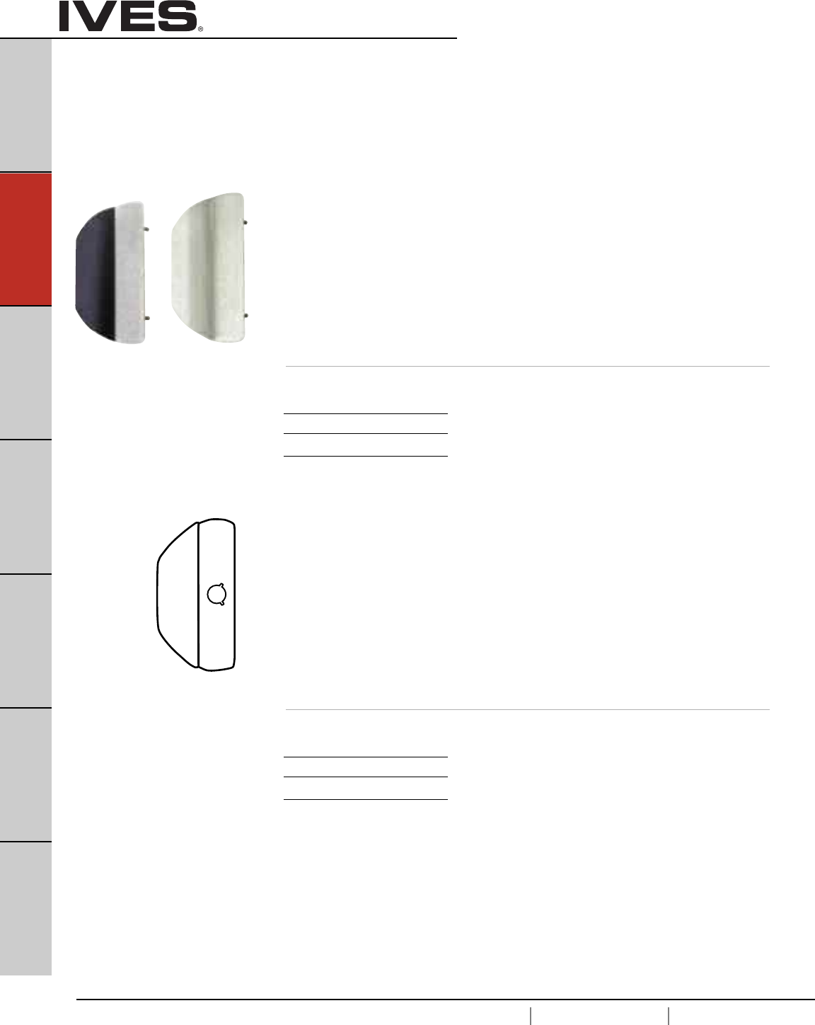
B10
USA 1.877.671.7011 Canada 1.905.403.1800 www.ives.ingersollrand.com
Vandal Resistant Trim
B10
Pulls & Plates
A
Hinges & Pivots
C
Flush Bolts & Coordinators
D
Latches, Catches & Bolts
E
Stops
F
Exterior Hardware
G
Miscellaneous Hardware
Vandal Resistant Trim
All stainless steel, 11 gauge (0.120” thick), using stainless steel fasteners for door
thickness of 1-3/4” to 2-1/4”. Built-in lock protector prevents tampering on
certain models. Protective cylinder collar spins to reduce damage from pipe wrench
or other tools. Models are available with or without attractive black plastisol
edge grip.
VR810-DT With black grip
VR814-DT Without black grip
• For use with Monarch XX, 18 Series or 25 Series rim exit device
• Non-handed
• Thru-bolts direct to the exit device
• Pull operation only
Prod. Thru-Bolt Clearance
No. Width Height Pattern Grip to Door Projection
VR810DT 5-1/4" 11" 1-3/4" Wide x 7-3/4" High 1-1/2" 1-7/8"
Finishes
US Finish US32D
BHMA 630
VR810-NL LHR With black grip
VR810-NL RHR With black grip
VR814-NL LHR Without black grip
VR814-NL RHR Without black grip
• For use with Monarch XX-V, 18-V Series or 25-V Series vertical
rod exit device
• Thru-bolts direct to the exit device
• Night latch operation (cylinder not furnished)
Prod. Thru-Bolt Clearance
No. Width Height Pattern Grip to Door Projection
VR810NL 5-1/4" 11" 1-3/4" Wide x 7-3/4" High 1-1/2" 1-7/8"
Finishes
US Finish US32D
BHMA 630
VR814 VR810
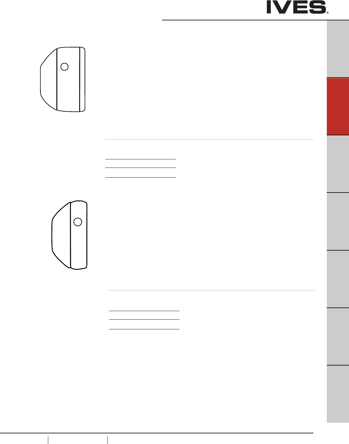
B11
USA 1.877.671.7011 Canada 1.905.403.1800 www.ives.ingersollrand.com
Vandal Resistant Trim
B11
Pulls & Plates
A
Hinges & Pivots
C
Flush Bolts & Coordinators
D
Latches, Catches & Bolts
E
Stops
F
Exterior Hardware
G
Miscellaneous Hardware
VR900 RHR With black grip
VR900 LHR With black grip
VR904 RHR Without black grip
VR904 LHR Without black grip
• For use with most mortise locks on outswinging doors including
• Schlage L9000 Series with interior L or N escutcheon, and rose trim.
• Includes built-in lock protector and cylinder cutout.
• Handed design allows trim to be positioned to coordinate with the
centerline of inside hardware.
Thru-Bolt Clearance
Width Height Pattern Grip to Door Projection
7-1/4" 11" 2" Wide x 10" High 1-1/2" 1-7/8"
VR900LLP RH With black grip
VR900LLP LH With black grip
VR904LLP RH Without black grip
VR904LLP LH Without black grip
• For use with most mortise locks on outswinging doors including
• Schlage L9000 Series with interior L or N escutcheon, and rose trim.
• Includes built-in lock protector and cylinder cutout.
• Handed design allows trim to be positioned to coordinate with the
centerline of inside hardware.
Thru-Bolt Clearance
Width Height Pattern Grip to Door Projection
5-1/4" 11" 1-3/4" Wide x 10" High 1-1/2" 1-7/8"
Finishes
US Finish US32D
BHMA 630
Finishes
US Finish US32D
BHMA 630
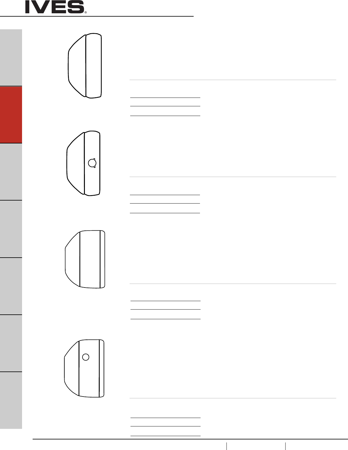
B12
USA 1.877.671.7011 Canada 1.905.403.1800 www.ives.ingersollrand.com
Vandal Resistant Trim
B12
Pulls & Plates
A
Hinges & Pivots
C
Flush Bolts & Coordinators
D
Latches, Catches & Bolts
E
Stops
F
Exterior Hardware
G
Miscellaneous Hardware
VR910-DT With black grip
VR914-DT Without black grip
• For use with Von Duprin 98/99 Series rim and vertical rod exit device
• Non-handed
• Thru-bolts direct to the exit device
• Pull operation only.
Thru-Bolt Clearance
Width Height Pattern Grip to Door Projection
5-1/4" 11" 1-3/8" Wide x 7" High 1-1/2" 1-7/8"
VR910-NL With black grip
VR914-NL Without black grip
• For use with Von Duprin 98/99 rim and vertical rod exit device
• Non-handed
• Thru-bolts direct to the exit device
Thru-Bolt Clearance
Width Height Pattern Grip to Door Projection
5-1/4" 11" 1-3/8" Wide x 7" High 1-1/2" 1-7/8"
VR910M-DT With black grip
VR914M-DT Without black grip
• For use with Von Duprin 9875/9975 mortise lock exit device
• Non-handed
• Thru-bolts direct to the exit device
Thru-Bolt Clearance
Width Height Pattern Grip to Door Projection
7-1/4" 11" 1-3/8" Wide x 7" High 1-1/2" 1-7/8"
VR910M-NL RHR With black grip
VR910M-NL LHR With black grip
VR914M-NL RHR Without black grip
VR914M-NL LHR Without black grip
• For use with Von Duprin 9875/9975 Series mortise lock exit device
• Thru-bolts direct to the exit device
• Night latch operation (cylinder not furnished)
Thru-Bolt Clearance
Width Height Pattern Grip to Door Projection
7-1/4" 11" 1-3/8" Wide x 7" High 1-1/2" 1-7/8"
Finishes
US Finish US32D
BHMA 630
Finishes
US Finish US32D
BHMA 630
Finishes
US Finish US32D
BHMA 630
Finishes
US Finish US32D
BHMA 630
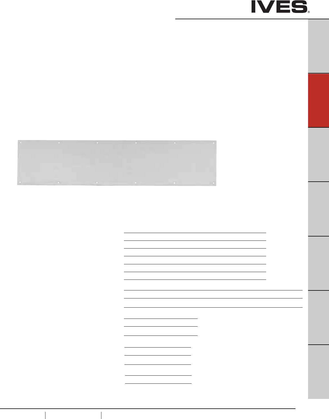
B13
USA 1.877.671.7011 Canada 1.905.403.1800 www.ives.ingersollrand.com
Protection Trim
B13
Pulls & Plates
A
Hinges & Pivots
C
Flush Bolts & Coordinators
D
Latches, Catches & Bolts
E
Stops
F
Exterior Hardware
G
Miscellaneous Hardware
8400 Series Protection Plates
• Door protection plates are available in .050” thick brass, stainless
steel or aluminum; and 1/8” thick high impact polyethylene in clear
or black.
•Bevel edge options; specify B4E for all four edges.
• Mounting screw pack furnished standard, 16 screws per pack.
Optional screw packs are available for TEK or TORK screw heads.
Refer to the following chart for ordering.
• Specify NMH for no mounting holes.
• Specify NMH-A for no mounting holes with adhesive.
• Specify CS for counter sunk mounting holes.
• Specify ERS prepped with extra row of screws.
Kickplate Gasket Tape Tape is recommended when using a
brass plate on a metal door to reduce tarnishing from electrolytic
oxidation. One tape pack will cover an the perimeters of a 8” x 34”
kickplate. Order 8401 Gasket Tape.
8400 Protection Plate
8402 (UL)* Protection Plate
*UL mark appears in upper right corner.
Number of screw packs required by plate size (specify TEK Screws or TORK screws).
22"-25" 26"-33" 34"-41" 42"-48"
4"-8" 11 1 1
9"-16" 11 1 1
17"-24" 11 1 2
25"-32" 11 2 2
33"-40" 12 2 2
41"-48" 22 2 2
Finishes brass
US Number US3 US4 US10 US10B US15 US26 US26D
BHMA 605 606 612 613 619 625 626
Finishes stainless steel
US Number US32 US32D
BHMA 629 630
Finishes aluminum
US Number US28
BHMA 628
Finishes plastic
Clear and Black
Residential Grade Kickplates available Carded only, finishes PA28, PA3, PA619,
PA716, B3, B505, B619, B716
B14
USA 1.877.671.7011 Canada 1.905.403.1800 www.ives.ingersollrand.com
Protection Trim
B14
Pulls & Plates
A
Hinges & Pivots
C
Flush Bolts & Coordinators
D
Latches, Catches & Bolts
E
Stops
F
Exterior Hardware
G
Miscellaneous Hardware
Mop Plates
• Protect the bottom of the pull side of door subject to cleaning
and mopping procedures.
• Size Ranges:4" to 6" high, 22" to 48" wide
Kick Plates
• Protect the bottom of the push side of doors subject to
scuffing from foot traffic.
• Recommended for all doors subject to normal use
(especially doors using a closer).
• Size Ranges: 8" to 24" high, 22" to 48" wide
Stretcher Plates
• Protect doors at specific areas where consistent contact is made by
stretchers, service carts or other equipment.
• Usually applied to push side of doors.
• Specify “B4E” Option for beveled edges.
• Size Ranges: 6" to 8" high, 22" to 48" wide
Armor Plates
• Protect lower half of doors from abuse by hard carts,
trucks and rough usage.
• Usually applied to push side of single doors and both sides
of double acting doors.
• Size Ranges: 26" to 48" high, 22" to 48" wide
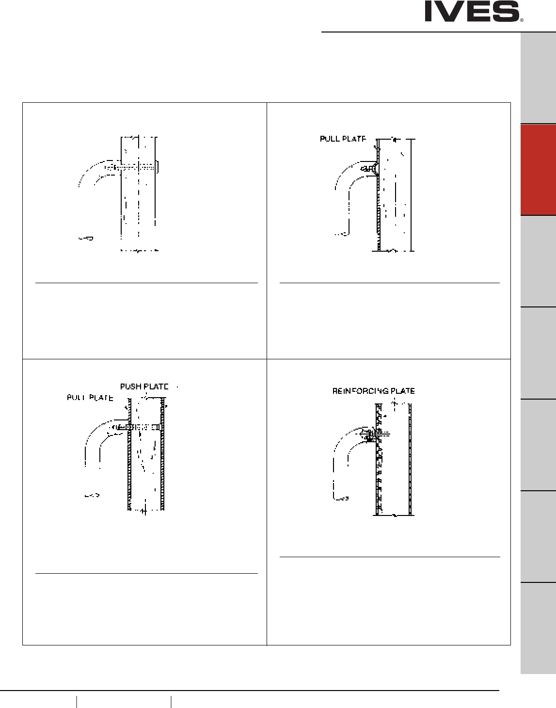
B15
USA 1.877.671.7011 Canada 1.905.403.1800 www.ives.ingersollrand.com
Push Plates
B15
Pulls & Plates
A
Hinges & Pivots
C
Flush Bolts & Coordinators
D
Latches, Catches & Bolts
E
Stops
F
Exterior Hardware
G
Miscellaneous Hardware
Wood Doors
Concealed Pull Mounting With Push Plate
• (2) 1/4-20 x 2-1/4" steel flat head machine screws; zinc plated.
Available only for 8102, 8103, 8105, 8111, 8302, 8303, 8305 and
8311. Plate on opposite side of door must be ordered separately.
Standard Mounting
• (2) 1/4-20 x 2-1/4" brass, oval head machine screws;
plated to match.
• (2) No. 14 countersunk washers; plated to match
Concealed Pull Plate Mounting
Available only for 8302, 8303, 8311 Pull Plates.
• (2) 1/4-20 x 5/8" steel flat head machine screws; zinc plated.
Pull mounts directly onto plate.
Plate is attached to door by 6 screws.
Reinforced Hollow Metal Door
Concealed Pull Mounting
Available only for 8102 8103, 8103EZ or wood door Pulls and
8302, 8303 pull plates.
• (2) Steel screw sleeves; zinc plated.
• (2) 1/4-20 x 1-1/4" steel countersunk trim head machine
screw; zinc plated for reinforced metal door.
• (2) 1/4 x 1-1/2" steel countersunk trim head steel metal screw;
zinc plated for wood doors.
Mounting
Standard Mount Type G Mount
• All mounting hardware is for standard 1-3/4" door.
•Consult Customer Service if other than standard.
Type F Mount Type H-I-L Mount
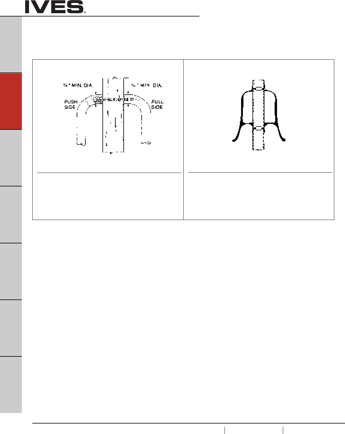
B16
USA 1.877.671.7011 Canada 1.905.403.1800 www.ives.ingersollrand.com
Architectural Door Trim
B16
Pulls & Plates
A
Hinges & Pivots
C
Flush Bolts & Coordinators
D
Latches, Catches & Bolts
E
Stops
F
Exterior Hardware
G
Miscellaneous Hardware
Mounting
• All mounting hardware is for standard 1-3/4" door.
• Consult Customer Service if other than standard.
Back to Back Pull Mounting
Available only for 8121-5 Pulls.
• (4) Steel screw sleeve nuts; steel zinc plated.
• (8) No. 8-32 x 1" brass oval head machine screws; plated to match.
Pulls furnished in pairs (PR).
Back to Back Pull Mounting
Available only for 8102, 8103, Pulls and 8302, 8303 Pull plates.
• (2) Steel screw sleeves; zinc plated.
• (2) 1/4-20 x 2-3/4" steel countersunk trim head
machine screws; zinc plated.
Pulls furnished in pairs (PR) unless single (SGL) specified.
Type J Mount Type K Mount
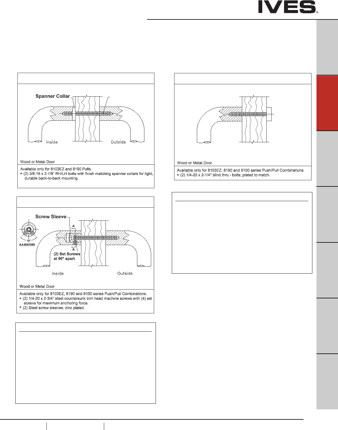
B17
USA 1.877.671.7011 Canada 1.905.403.1800 www.ives.ingersollrand.com
Architectural Door Trim
B17
Pulls & Plates
A
Hinges & Pivots
C
Flush Bolts & Coordinators
D
Latches, Catches & Bolts
E
Stops
F
Exterior Hardware
G
Miscellaneous Hardware
Type NS-Standard Push/Pull Mounting
Type N & Standard
Pushbar to Pull
- (1) 1/4-20 X 3"steel countersunk trim head machine screws
with (2) set screws.
- (1) steel screw sleeve, zinc plated.
Free End Pushbar & Pull
- (2) 1/4-20 X 2-1/4" brass, oval head mach screws;
plated to match.
- (2) No. 14 countersunk washers; plated to match.
Type NO Push/Pull Mounting
Type N & Type O
Pushbar to Pull
- (1) 1/4-20 X 3"steel countersunk trim head machine screws
with (2) set screws.
- (1) steel screw sleeve, zinc plated.
Free End Pushbar & Pull
- (2) 1/4-20 X 2-1/4" blind thru-bolts; plated to match.
Mounting for 8103EZ, 8190, 9100, 9103EZ and 9190
• All mounting hardware is for standard 1-3/4" door.
• Consult Customer Service if other than standard.
Type M Mount
Type N Mount
Type O Mount
Back-to-Back with Spanner Collar Decorative Blind Thru - Bolt
Pulls furnished in pairs (PR) or Single
(SGL) must specify M1 or RH thread or M2 for LH thread.
RH (M1) and
LH (M2) Thread
(push)
Back-to-Back “Two-Anchor”
(pull)

B18
USA 1.877.671.7011 Canada 1.905.403.1800 www.ives.ingersollrand.com
Notes
B18
Pulls & Plates
A
Hinges & Pivots
C
Flush Bolts & Coordinators
D
Latches, Catches & Bolts
E
Stops
F
Exterior Hardware
G
Miscellaneous Hardware
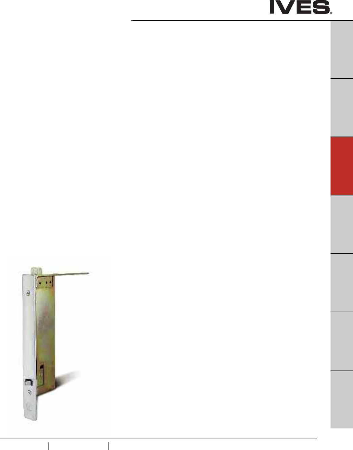
C1
USA 1.877.671.7011 Canada 1.905.403.1800 www.ives.ingersollrand.com
Flush Bolts and Coordinators
B
Pulls & Plates
A
Hinges & Pivots
C1
Flush Bolts & Coordinators
D
Latches, Catches & Bolts
E
Stops
F
Exterior Hardware
G
Miscellaneous Hardware
Table Of Contents
Flush Bolts page
FB31, FB32, FB33 Automatic Flush Bolt . . . . . . . . . . . . . . . . . . . . . . . . .C2
FB41, FB42 Automatic Flush Bolt . . . . . . . . . . . . . . . . . . . . . . . . . . . . . .C3
FB51, FB52, FB53 Automatic Flush Bolt . . . . . . . . . . . . . . . . . . . . . . . . .C4
FB61, FB62 Constant Latching Flush Bolt . . . . . . . . . . . . . . . . . . . . . . . .C5
261 Manual Flush Bolt . . . . . . . . . . . . . . . . . . . . . . . . . . . . . . . . . . . . . . .C6
262 Manual Flush Bolt . . . . . . . . . . . . . . . . . . . . . . . . . . . . . . . . . . . . . . .C6
265 Manual Flush Bolt . . . . . . . . . . . . . . . . . . . . . . . . . . . . . . . . . . . . . . .C7
FB358 Manual Flush Bolt . . . . . . . . . . . . . . . . . . . . . . . . . . . . . . . . . . . . .C8
FB457 Manual Flush Bolt . . . . . . . . . . . . . . . . . . . . . . . . . . . . . . . . . . . . .C9
FB458 Manual Flush Bolt . . . . . . . . . . . . . . . . . . . . . . . . . . . . . . . . . . . .C10
DP1, DP2 Dust Proof Strike . . . . . . . . . . . . . . . . . . . . . . . . . . . . . . . . . .C11
Coordinators
COR Series Bar Coordinator . . . . . . . . . . . . . . . . . . . . . . . . . . . . . . . . . .C12
FL Series Filler bar . . . . . . . . . . . . . . . . . . . . . . . . . . . . . . . . . . . . . . . . .C12
MB1, MB2 Mounting Brackets . . . . . . . . . . . . . . . . . . . . . . . . . . . . . . . .C13
MB1F, MB2F, MB3F Mounting Brackets . . . . . . . . . . . . . . . . . . . . . . . .C13
MB1V, MB2V, MB3V Mounting Brackets . . . . . . . . . . . . . . . . . . . . . . . .C13
COR7G, CORG Gravity Coordinator . . . . . . . . . . . . . . . . . . . . . . . . . . . .C14
CB1 Carry Bar . . . . . . . . . . . . . . . . . . . . . . . . . . . . . . . . . . . . . . . . . . . . .C14
How to order . . . . . . . . . . . . . . . . . . . . . . . . . . . . . . . . . . . . . . . . . . . . .C15
Special factory prep . . . . . . . . . . . . . . . . . . . . . . . . . . . . . . . . . . . . . . . .C16
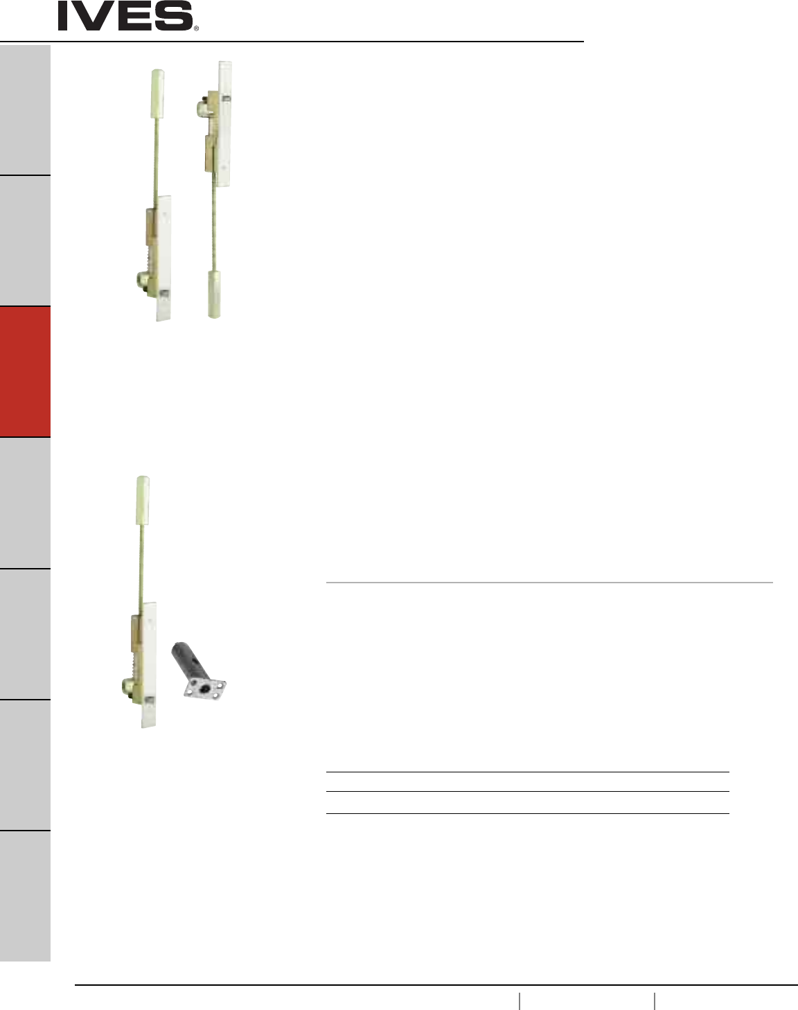
C2
USA 1.877.671.7011 Canada 1.905.403.1800 www.ives.ingersollrand.com
Automatic Flush Bolts – Metal Doors
B
Pulls & Plates
A
Hinges & Pivots
C2
Flush Bolts & Coordinators
D
Latches, Catches & Bolts
E
Stops
F
Exterior Hardware
G
Miscellaneous Hardware
FB31P Top and Bottom Bolts (Pair)
• Fully Automatic—inactive door is latched, bolts are extended when
active door closes, door is unlatched, bolts retract when active door
is opened.
• Low Actuation Forces—Top Bolt Has No Spring Tension.
• Fits standard ANSI A115.4 Door Frame Preparations.
• Non-handed.
• Bolt throw is 3/4" with a 7/8" vertical adjustment.
• Bolt backset is 3/4"
• Standard Rod Length is 12", which is measured from the center
of the flush bolt body to the bolt tip. Optional rod lengths available
for top bolt only on non-fire rated openings—18", 24", 36" and 48.
DP1 or DP2 optional dust proof strike available, see page C11.
FB31T Top Bolt Only
FB31B Bottom Bolt Only
FB32 Top Bolt with Auxiliary Fire Latch
• FB32 Model with Auxiliary Fire Latch eliminates the bottom bolt
and is UL Listed for Fire Doors.
FB33 Top Bolt with Auxiliary Fire Latch and Retrofit Plate
• FB33 Model with Auxillary Fire Latch eliminates the bottom bolt and
includes a retrofit plate to cover existing bottom bolt prep.
UL Listed for Fire Doors.
Dimensions
Body Size: 1" Wide x 6-3/4" Long x 2" Deep
Guide Size: 1" Wide x 1-27/32" Long x 27/32" High x 3/32" Thick
Strike Size: 15/16" Wide x 2-1/4" Long x 1/16" Thick
Rub Plate Size: 1-1/4" Wide x 1-11/16" Long x 3/64" Thick
Auxiliary Fire Latch Size: 1" Wide x 1-3/4" Long x 3-1/4" Deep
Retrofit Plate Size: 1" Wide x 6-3/4" Long x 3/32" Thick
Meets ANSI A156.3 Type 25.
UL Listed 3 Hour Fire Doors 8'0" x 10'0"
Meets ANSI A156.3 Type 25.
UL Listed 3 Hour Fire Doors 8'0" x 10'0"
Finishes
Ives Number US3 US4 US10 US10B US32 US32D
BHMA 605 606 612 613 629 630
Top
Bolt
Top
Bolt
Auxiliary
Fire Latch
Bottom
Bolt
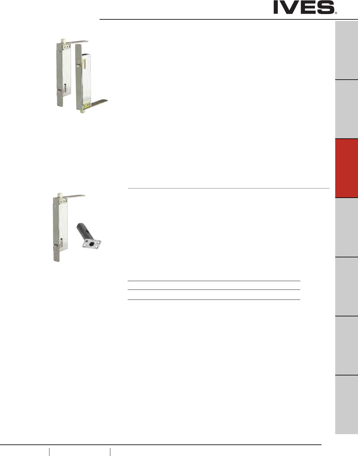
C3
USA 1.877.671.7011 Canada 1.905.403.1800 www.ives.ingersollrand.com
Automatic Flush Bolts – Wood Doors
B
Pulls & Plates
A
Hinges & Pivots
C3
Flush Bolts & Coordinators
D
Latches, Catches & Bolts
E
Stops
F
Exterior Hardware
G
Miscellaneous Hardware
FB41P Top and Bottom Bolts (Pair)
• Fully Automatic—inactive door is latched, bolts are extended when
active door closes, door is unlatched bolts retract when active door
is opened.
• Low Actuation Forces—Top Bolt Has No Spring Tension.
• Non-handed.
• Bolt throw is 3/4" with a 7/8" vertical adjustment.
• Bolt backset is 3/4"
DP1 or DP2 optional dust proof strike available, see page C11.
FB41T Top Bolt Only
FB41B Bottom Bolt Only
FB42 Top Bolt with Auxiliary Fire Latch
• FB42 Model with Auxiliary Fire Latch eliminates the bottom bolt
and is UL Listed for Fire Doors.
Dimensions
Body Size: 1" Wide x 8-1/2" Long x 2" Deep
Guide Size: 1" Wide x 6" Long x 1/8" Thick
Strike Size: 15/16" Wide x 2-1/4" Long x 1/16" Thick
Rub Plate Size: 1-1/4" Wide x 1-11/16" Long x 3/64" Thick
Auxiliary Fire Latch Size: 1" Wide x 1-3/4" Long x 3-1/4" Deep
Meets ANSI A156.3 Type 25.
UL Listed 90 Minute Fire Doors 8'0" x 8'0"
Finishes
Ives Number US3 US4 US10 US10B US32 US32D
BHMA 605 606 612 613 629 630
Top
Bolt
Meets ANSI A156.3 Type 25.
UL Listed 20 Minute Fire Doors 8'0" x 8'0"
Top
Bolt
Bottom
Bolt
Auxiliary
Fire Latch
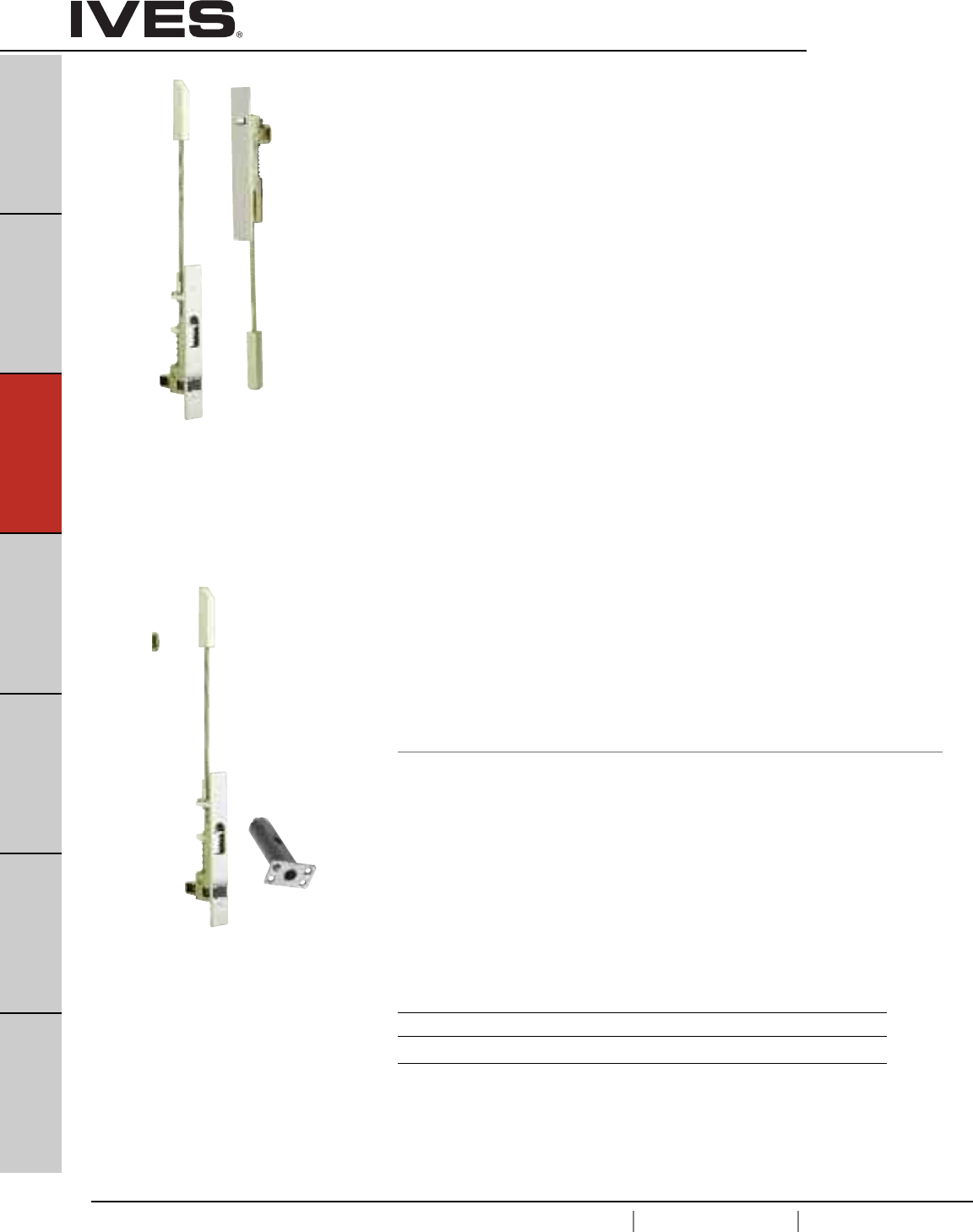
C4
USA 1.877.671.7011 Canada 1.905.403.1800 www.ives.ingersollrand.com
Constant Latching Flush Bolts – Metal Doors
B
Pulls & Plates
A
Hinges & Pivots
C4
Flush Bolts & Coordinators
D
Latches, Catches & Bolts
E
Stops
F
Exterior Hardware
G
Miscellaneous Hardware
FB51P Top and Bottom Bolts (Pair)
• Constant Latching—inactive door remains latched until
the active door is opened, releasing the automatic bottom
bolt and then the top bolt can be manually released.
Inactive door will relatch automatically when closed.
• Low Actuation Forces.
• Fits standard ANSI A115.4 Door and Frame Preparations.
• Non-handed.
• 3/4" bolt throw with a 7/8" vertical adjustment.
• 3/4" backset
• Standard Rod Length is 12", which is measured from the center
of the flush bolt body to the bolt tip. Optional rod lengths available
for top bolt only on non-fire rated openings—18", 24", 36" and 48".
DP1 or DP2 optional dust proof strike available, see page C11.
FB51T Top Bolt Only
FB52 Top Bolt with Auxiliary Fire Latch
• FB52 Model with Auxiliary Fire Latch eliminates the bottom bolt
and is UL Listed for Fire Doors.
FB53 Top Bolt with Auxiliary Fire Latch & Retrofit Plate
• FB53 Model with Auxiliary Fire Latch eliminates the bottom bolt
and includes a retrofit plate to cover existing bottom bolt prep.
UL Listed for Fire Doors.
Dimensions
Body Size: 1" Wide x 6-3/4" Long x 2" Deep
Guide Size: 1" Wide x 1-27/32" Long x 11/16" High x 3/32" Thick
Strike Size: 15/16" Wide x 2-1/4" Long x 1/16" Thick
Rub Plate Size: 1-1/4" Wide x 1-11/16" Long x 3/64" Thick
Auxiliary Fire Latch Size: 1" Wide x 1-3⁄4" Long x 3-1/4" Deep
Retrofit Plate Size: 1" Wide x 6-3/4" Long x 3/32" Thick
Meets ANSI A156.3 Type 27.
UL Listed 3 Hour Fire Doors 8'0" x 10'0"
Finishes
Ives Number US3 US4 US10 US10B US32 US32D
BHMA 605 606 612 613 629 630
Meets ANSI A156.3 Type 27.
UL Listed 3 Hour Fire Doors 8'0" x 10'0"
Top
Bolt
Auxiliary
Fire Latch
Top
Bolt
Bottom
Bolt
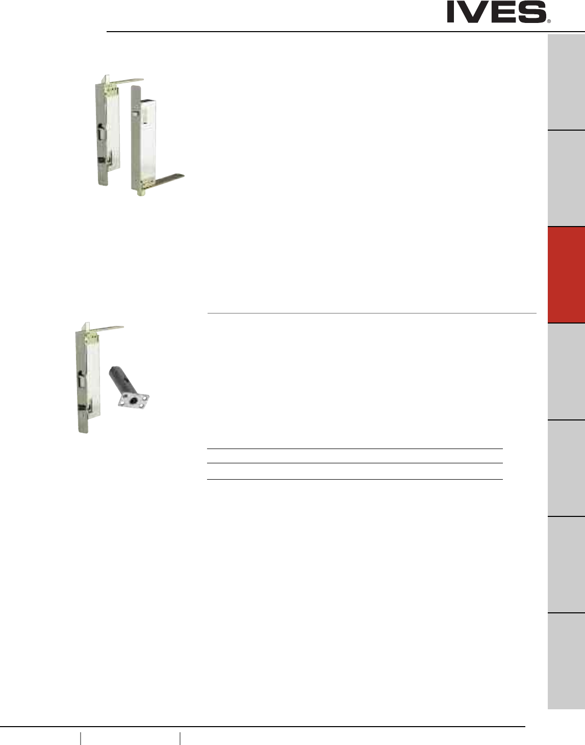
C5
USA 1.877.671.7011 Canada 1.905.403.1800 www.ives.ingersollrand.com
Constant Latching Flush Bolts – Wood Doors
B
Pulls & Plates
A
Hinges & Pivots
C5
Flush Bolts & Coordinators
D
Latches, Catches & Bolts
E
Stops
F
Exterior Hardware
G
Miscellaneous Hardware
FB61P Top and Bottom Bolts (Pair)
•Constant Latching—inactive door remains latched until the
active door is opened, releasing the automatic bottom bolt and
then the top bolt can be manually released. Inactive door will
relatch automatically when door closes.
• Low Actuation Forces.
• Non-handed.
• Bolt throw is 3/4" with a 7/8" vertical adjustment.
• Bolt backset is 3/4"
DP1 or DP2 optional dust proof strike available, see page C11.
FB61T Top Bolt Only
FB62 Top Bolt with Auxiliary Fire Latch
• FB62 Model with Auxiliary Fire Latch eliminates the bottom bolt
and is UL Listed for Fire Doors..
Dimensions
Body Size: 1" Wide x 8-1/2" Long x 2" Deep
Guide Size: 1" Wide x 6" Long x 1/8" Thick
Strike Size: 15/16" Wide x 2-1/4" Long x 1/16" Thick
Rub Plate Size: 1-1/4" Wide x 1-11/16" Long x 3/64" Thick
Auxiliary Fire Latch Size: 1" Wide x 1-3/4" Long x 3-1/4" Deep
Finishes
Ives Number US3 US4 US10 US10B US32 US32D
BHMA 605 606 612 613 629 630
Meets ANSI A156.3 Type 27.
UL Listed 90 Minute Fire Doors 8'0" x 8'0"
Auxiliary
Fire Latch
Top
Bolt
Bottom
Bolt
Meets ANSI A156.3 Type 27.
UL Listed 20 Minute Fire Doors 8'0" x 8'0"
Top
Bolt
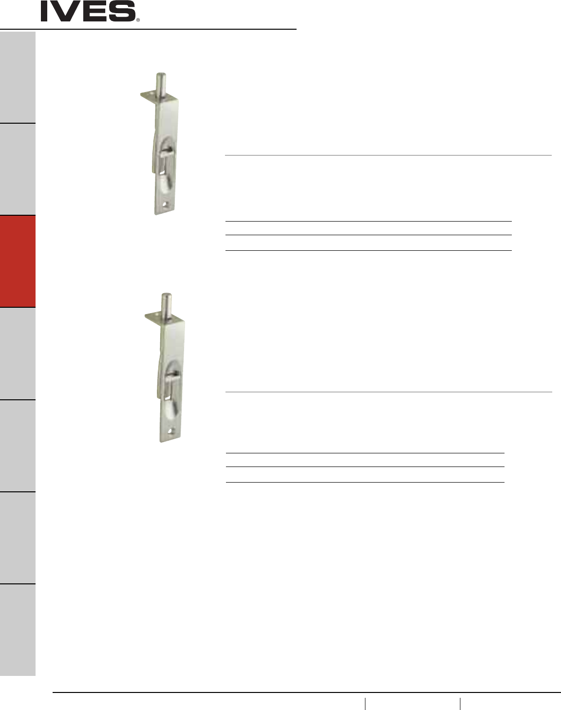
C6
USA 1.877.671.7011 Canada 1.905.403.1800 www.ives.ingersollrand.com
Manual Flush Bolts
B
Pulls & Plates
A
Hinges & Pivots
C6
Flush Bolts & Coordinators
D
Latches, Catches & Bolts
E
Stops
F
Exterior Hardware
G
Miscellaneous Hardware
262 Flush Bolt
• An exceptionally smooth working flush bolt with sharp, crisp lines.
• Double action spring design provides automatic holding of brass
bolt in projected or retracted position, and assures ease of
operation in conjunction with deep cup finger hole.
• Made from polished cast brass.
• Bolt tip is 1/2" Diameter
• Bolt throw is 1"
• Bolt backset is 15/32"
Dimensions
Body Size: 3/4" W x 6" L x 1-11/32" D
Strike Size: 7/8" W x 1-3/4" L
Meets ANSI/BHMA A156.16, L04201.
Meets ANSI/BHMA A156.16, L04201.
Finishes
Ives Number B3 B5 B10B B15 B26 B26D
BHMA 605 609 613 619 625 626
Finishes
Ives Number B3 B5 B10B B15 B26 B26D
BHMA 605 609 613 619 625 626
261 Flush Bolt
• An exceptionally smooth working flush bolt with sharp, crisp lines.
• Double action spring design provides automatic holding of brass
bolt in projected or retracted position, and assures ease of
operation in conjunction with deep cup finger hole.
• Made from polished cast brass.
• Bolt tip is 5/16" Diameter
• Bolt throw is 3/4"
• Bolt backset is 15/32"
Dimensions
Body Size: 3/4" Wide x 4" Long x 1-1/8" Deep
Strike Size: 5/8" Wide x 1-1/2" Long
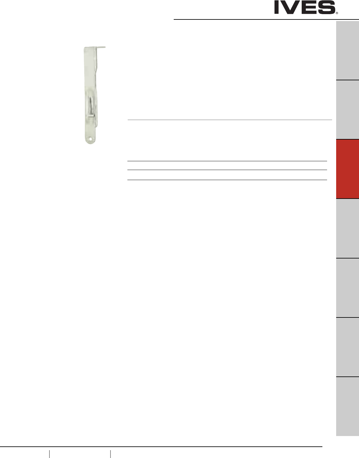
C7
USA 1.877.671.7011 Canada 1.905.403.1800 www.ives.ingersollrand.com
Manual Flush Bolts
B
Pulls & Plates
A
Hinges & Pivots
C7
Flush Bolts & Coordinators
D
Latches, Catches & Bolts
E
Stops
F
Exterior Hardware
G
Miscellaneous Hardware
265 Flush Bolt
• A flush bolt with radiused bottom faceplate designed specifically
for simple one-step router installation.
• Double action spring design provides automatic holding of brass
bolt in projected or retracted position, and assures ease of
operation in conjunction with deep cup finger hole.
• Faceplate is polished solid brass; bolt is made from aluminum zinc alloy.
• Bolt tip is 1/2" Diameter
• Bolt throw is 1"
• Bolt backset is 1/2"
Dimensions
Body Size: 3/4" W x 6" L x 1-7/16" D
Strike Size: 7/8" W x 1-3/4" L
Finishes
Ives Number B3 B5 B10B B15 B26 B26D
BHMA 605 609 613 619 625 626
Meets ANSI/BHMA A156.16, L04201.
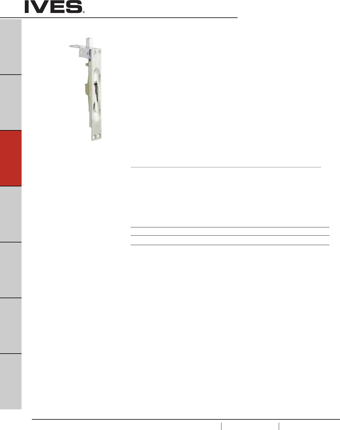
C8
USA 1.877.671.7011 Canada 1.905.403.1800 www.ives.ingersollrand.com
Manual Flush Bolts – Wood Doors
B
Pulls & Plates
A
Hinges & Pivots
C8
Flush Bolts & Coordinators
D
Latches, Catches & Bolts
E
Stops
F
Exterior Hardware
G
Miscellaneous Hardware
FB358 Top or Bottom Bolts
• When the active door is opened, the lever can be moved to the
‘up’ position, retracting the bolt and allowing the inactive leaf to be
opened. When the inactive leaf is closed, the lever can be moved to
the ‘down’ position, projecting the bolt into the strike and securely
locking the inactive leaf.
• Reduces installation costs; requires only simple router mortise
at top and bottom corners of doors.
• Door strength and rigidity maintained by tying door faces to
reinforcing extensions on guide with machine screws and
bearing washers, not supplied.
• Non-handed.
• Bolt tip 1/2" diameter
• Bolt throw is 3/4" with a 7/8" vertical adjustment.
• Bolt backset is 3/4"
• Not available for rabbeted door installations.
DP1 or DP2 optional dust proof strike available, see page C11.
Dimensions
Body Size: 1" Wide x 6-3/4" Long x 1-3/8" Deep
Guide Size: 1" Wide x 2-1/2" Long x 5/64" Thick
Strike Size: 15/16" Wide x 2-1/4" Long x 5/64" Thick
Meets ANSI/BHMA A156.16, L04261.
UL Listed 90 Minute Fire Doors 8'0" x 10'0"
Finishes
Ives Number US3 US4 US10 US10B US15 US26 US26D
BHMA 605 606 612 613 619 625 626
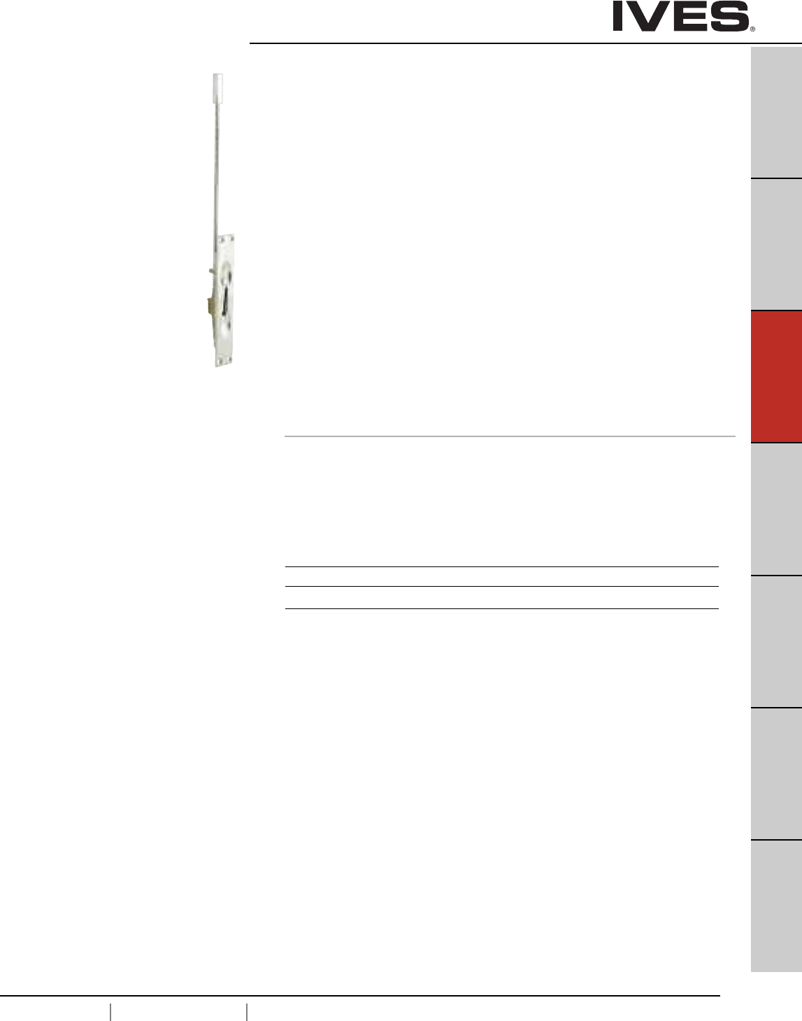
C9
USA 1.877.671.7011 Canada 1.905.403.1800 www.ives.ingersollrand.com
Manual Flush Bolts – Metal Doors
B
Pulls & Plates
A
Hinges & Pivots
C9
Flush Bolts & Coordinators
D
Latches, Catches & Bolts
E
Stops
F
Exterior Hardware
G
Miscellaneous Hardware
FB457 Top or Bottom Bolts
• When the active door is opened, the lever can be moved to the
‘up’ position, retracting the bolt and allowing the inactive leaf to be
opened. When the inactive leaf is closed, the lever can be moved to
the ‘down’ position, projecting the bolt into the strike and securely
locking the inactive leaf.
• Simplified installation in metal frames. Round bolt head requires only
a punched hole. Use of strike optional. Special design of guide and
flat sided bolt tip to prevent bolt rotation.
• Non-handed.
• Bolt tip is 1/2" Diameter.
• Bolt throw is 3/4" with a 7/8" vertical adjustment.
• Bolt backset is 3/4"
• Standard Rod Length is 12", which is measured from the center
of the flush bolt body to the bolt tip. Optional rod lengths available -
6", 9", 18" and 24" for fire rated doors. Optional rod lengths available -
6", 9", 18", 24", 30", 36" and 48" for non-fire rated doors.
DP1 or DP2 optional dust proof strike available, see page C11.
Dimensions
Body Size: 1-1/4" Wide x 6-3/4" Long x 1-1/8" Deep
Guide Size: 1" Wide x 2" Long x 5/64" Thick
Strike Size: 15/16" Wide x 2-1/4" Long x 5/64" Thick
Meets ANSI/BHMA A156.16, L04251.
UL Listed 3 Hour Fire Doors 8'0" x 10'0"
Finishes
Ives Number US3 US4 US10 US10B US15 US26 US26D
BHMA 605 606 612 613 619 625 626
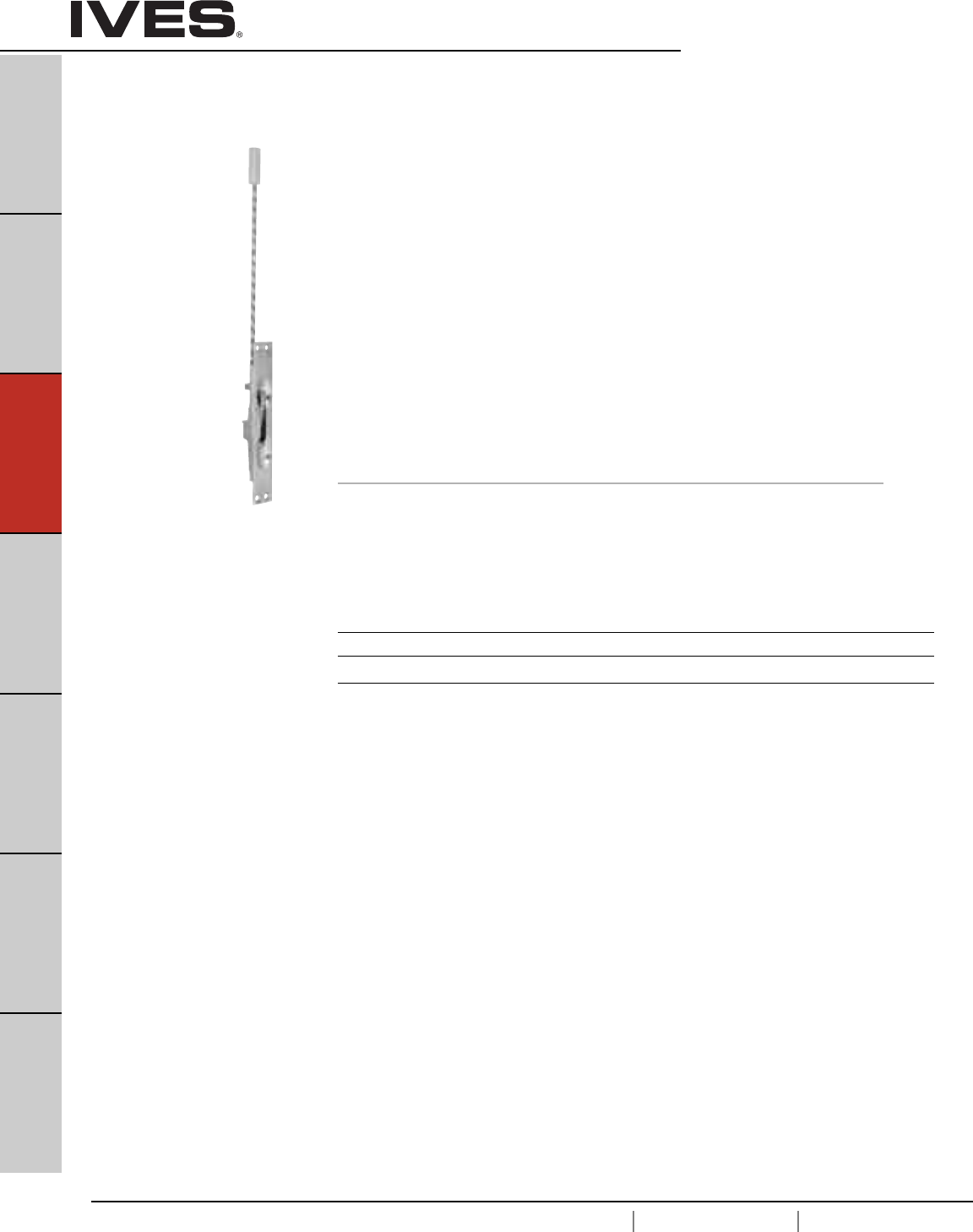
C10
USA 1.877.671.7011 Canada 1.905.403.1800 www.ives.ingersollrand.com
Manual Flush Bolts – Metal Doors
B
Pulls & Plates
A
Hinges & Pivots
C10
Flush Bolts & Coordinators
D
Latches, Catches & Bolts
E
Stops
F
Exterior Hardware
G
Miscellaneous Hardware
FB458 Top or Bottom Bolts
• When the active door is opened, the lever can be moved to the ‘up’
position, retracting the bolt and allowing the inactive leaf to be
opened. When the inactive leaf is closed, the lever can be moved to
the ‘down’ position, projecting the bolt into the strike and securely
locking the inactive leaf.
• Simplified installation in metal frames. Round bolt head requires only
a punched hole. Use of strike optional. Special design of guide and
flat sided bolt tip to prevent bolt rotation.
• Non-handed.
• Bolt tip is 1/2" diameter.
• Bolt throw is 3/4" with a 7/8" vertical adjustment.
• Bolt backset is 3/4"
• Standard Rod Length is 12", which is measured from the center
of the flush bolt body to the bolt tip. Optional Rod Lengths available -
6", 9", 18" and 24" for fire rated Doors. Optional Rod lengths
available - 6", 9", 18", 24", 30", 36" and 48" for non-fire rated doors.
DP1 or DP2 optional dust proof strike available, see page C11.
Dimensions
Body Size: 1" Wide x 6-3/4" Long x 1-1/8" Deep
Guide Size: 1" Wide x 2" Long x 5/64" Thick
Strike Size: 15/16" Wide x 2-1/4" Long x 5/64" Thick
Meets ANSI/BHMA A156.16, L04251.
UL Listed 90 Minute Fire Doors 8'0" x 10'0"
Finishes
Ives Number US3 US4 US5 US10 US10B US15 US26 US26D
BHMA 605 606 609 612 613 619 625 626
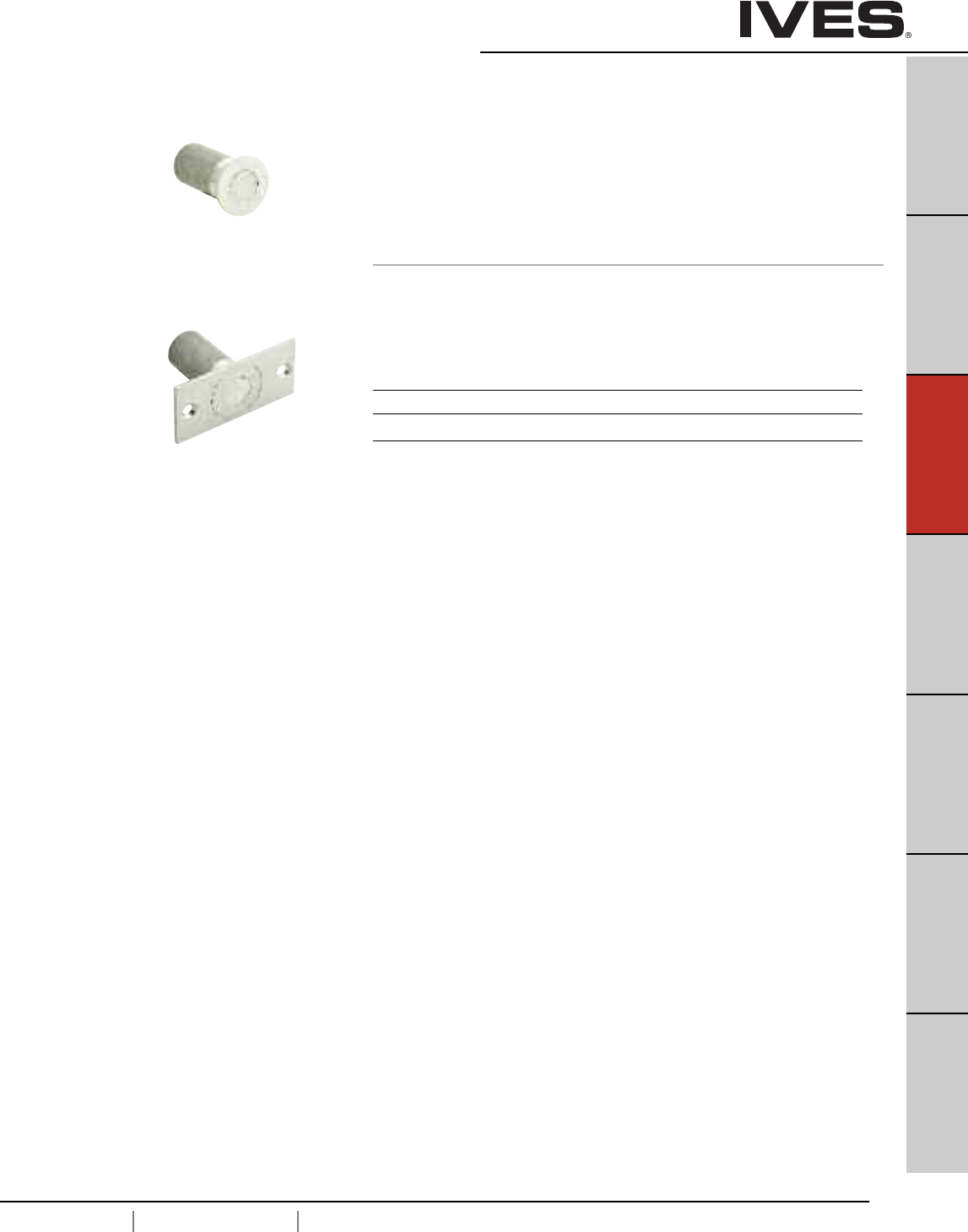
C11
USA 1.877.671.7011 Canada 1.905.403.1800 www.ives.ingersollrand.com
Dust Proof Strikes
B
Pulls & Plates
A
Hinges & Pivots
C11
Flush Bolts & Coordinators
D
Latches, Catches & Bolts
E
Stops
F
Exterior Hardware
G
Miscellaneous Hardware
DP1
DP2 Dust Proof Strikes
• Designed for use with the bottom bolt of all flush bolts.
• Spring-loaded plunger returns to floor or threshold level anytime
flush bolt is retracted, eliminating need to clean standard
floor strikes.
• Strike hole is 3/4" Diameter and 1-1/8" Deep
Dimensions
DP1 Face Plate: 1-7/16" Diameter
DP2 Face Plate: 1-5/8" W x 3-1/2" L x 1/8" Thick
Body: 1-3/16" Diameter x 1-7/8" Deep
DP1
DP2
Meets Meets ANSI/BHMA 156.16, L14011.
Finishes
Ives Number US3 US4 US10 US10B US26 US26D
BHMA 605 606 612 613 625 626
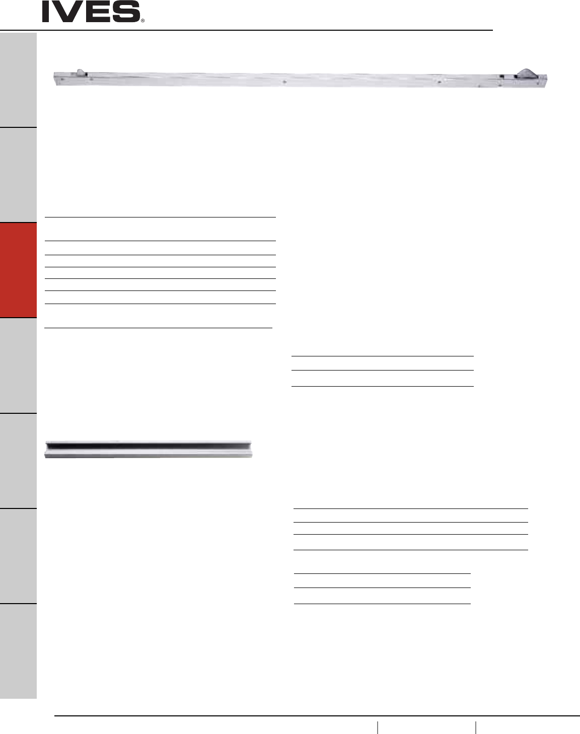
C12
USA 1.877.671.7011 Canada 1.905.403.1800 www.ives.ingersollrand.com
Coordinators – Bar Coordinators and Filler Bars
B
Pulls & Plates
A
Hinges & Pivots
C12
Flush Bolts & Coordinators
D
Latches, Catches & Bolts
E
Stops
F
Exterior Hardware
G
Miscellaneous Hardware
COR Series Bar Coodinators
• The COR Series Coordinators are designed for use on pairs of doors
when one door needs to close before the other.
• All COR units function easily. The active door lever, located nearest to
the active stop, holds the active door open until the trigger
mechanism is released by the closing of the inactive leaf.
• All COR units may not function correctly with swingclear hinges.
• All COR units are equipped with an adjustable override feature which
allows the active door to close under extreme pressure.
• All COR units are compatible with Flush Bolts.
• The COR Series is available in five sizes for variable door opening
widths.
• The COR Series does not cover the entire length of the stop,
so a FL filler bar can be provided to maintain architecturally clean lines.
• COR Series Coordinator Channels and FL fillers are made of aluminum.
• Optional Filler Bars: FL20 - 20", FL32 - 32" and FL44 - 44", available
to maintain clean line.
• Optional Mounting Brackets available: MB1, MB2, MB1F, MB2F,
MB3F, MB1V, MB2V, and MB3V for other stop applied hardware.
FL Series Filler Bars
• The FL Filler Bars are available in three sizes for variable frame
openings.
• FL Filler Bars are made of aluminum
• FL Filler Bars are field sized to frame opening.
For Openings Where Doors Are Same Size
Coordinator Length of For Opening Common
Number Channel Widths Applications
COR32 32" 34" - 52" Pair of 2'0" Doors
COR42 42" 52" - 72" Pair of 2'6" Doors
COR52 52" 62" - 92" Pair of 3'0" Doors
COR60 60" 70" - 108" Pair of 3'6" Doors
COR72 72" 84" - 132" Pair of 4'0" Doors
For Openings Where Doors Are Unequal Size
The coordinator length should equal the active door width plus
approximately 1/2 the inactive door width. The coordinator must
be 6" longer than the active door width and shorter than the overall
frame opening between stops.
Filler Bar
Number Length Dimensions
FL20 20" 1-5/8" W x 5/8" D x 20" L
FL32 32" 1-5/8" W x 5/8" D x 32" L
FL44 44" 1-5/8" W x 5/8" D x 44" L
Meets ANSI/BHMA A156.3, Type 21A.
UL Listed for installation on labeled frame.
Finishes
Ives Finish US28 US26D 315AN
BHMA 628 713 711
Finishes
Ives Finish US28 US26D 315AN
BHMA 628 713 711
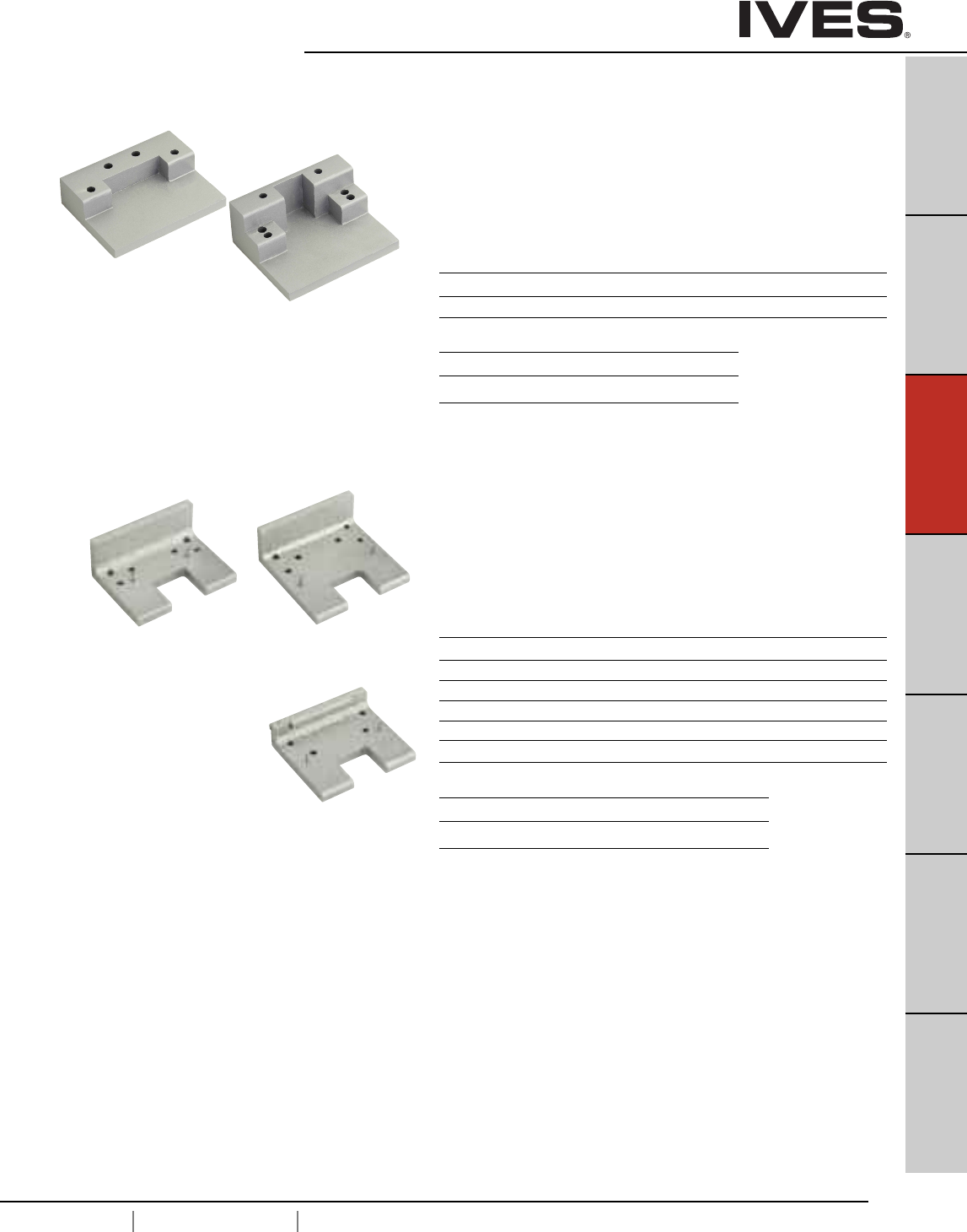
C13
USA 1.877.671.7011 Canada 1.905.403.1800 www.ives.ingersollrand.com
Coordinators – Mounting Brackets
B
Pulls & Plates
A
Hinges & Pivots
C13
Flush Bolts & Coordinators
D
Latches, Catches & Bolts
E
Stops
F
Exterior Hardware
G
Miscellaneous Hardware
MB1and MB2 Mounting Brackets
• Allows stop mounted hardware to be properly installed without
damaging the COR coordinator, such as a parallel arm closer or
a non-fire-rated surface vertical rod strike.
• Stop mounted hardware will need to be lowered to compensate
for the height of the coordinator and mounting bracket.
• MB mounting brackets are made of aluminum
MB1F, MB2F and MB3F Fire Rated Mounting Brackets
MB1V, MB2V and MB3V • Allows for fire-rated stop mounted hardware to be properly installed
without damaging the COR Coordinators, such as fire-rated surface
vertical rod exit device strikes.
• Latch will need to be lowered to compensate for the height of the
coordinator and mounting bracket.
• MB-V are designed for Von Duprin 8827-F soffit latch.
• Mounting brackets are made of steel.
Product Jamb Depth Stop Width Dimensions
MB1 4-3/4" Min. Over 2-1/2" 4" W x 3" D x 15/16" T
MB2 4-3/4" Min. Up to 2-1/2" 4" W x 3-1/4" D x 1-5/8" T
Product Jamb Depth Stop Width Dimensions
MB1F 5" 1-1/2" - 2-1/4" 4" W x 3" D x 1-5/8" T
MB1V 5" 1-1/2" - 2-1/4" 4" W x 3" D x 1-5/8" T
MB2F 5-7/8" 2-3/8" - 3-1/4" 4"W x 4" D x 1-5/8"T
MB2V 5-7/8" 2-3/8" - 3-1/4" 4"W x 4" D x 1-5/8"T
MB3F 6-7/8" Over 3-3/8" 4"W x 3-1/2" D x 1"T
MB3V 6-7/8" Over 3-3/8" 4"W x 3-1/2" D x 1"T
Finishes
Ives Finish USP SP28 SPBLK
BHMA 600 689 622
Finishes
Ives Finish USP SP28 SPBLK
BHMA 600 689 622
MB1V MB2V
MB3V
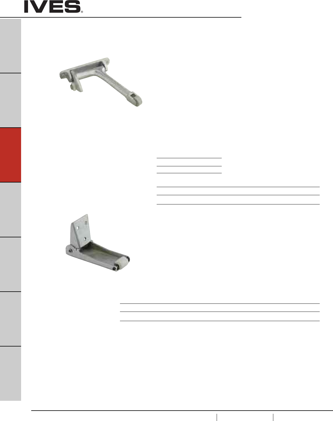
C14
USA 1.877.671.7011 Canada 1.905.403.1800 www.ives.ingersollrand.com
Coordinators – Gravity Coordinators
B
Pulls & Plates
A
Hinges & Pivots
C14
Flush Bolts & Coordinators
D
Latches, Catches & Bolts
E
Stops
F
Exterior Hardware
G
Miscellaneous Hardware
COR7G and Gravity Coordinators
COR9G • When active door is open, coordinator prevents active door from
closing until inactive door bypasses. Closing of inactive door causes
strike plate on top of door to contact cam and lift arm, allowing active
door to close. As inactive door continues closing, roller rides over
strike plate on to door bracket, holding arm above active door.
• Non-handed.
• Gravity action arm and door bracket are adjustable on the job for ease
of installation. Rubber roller provides quiet and efficient operation, and
helps protect the astragal and doors from damage.
• Nylon roller on short arm glides smoothly over door bracket
and strike, ensuring silent operation.
• Made of forged brass.
• COR7G for use on pairs of doors with astragal on active door up
to 4' or with astragal on inactive door up to 3'4" or with astragal on
both doors up to 2'10"
• COR9G for use on pairs of doors with astragal on active over 4' or
with astragal on inactive door over 3'4" or with astragal on both doors
over 2'10"
CB1 Carry Bar
• Used when it is possible for the inactive door
to be opened before the active door.
• Prevents damage to the doors and other hardware.
• Nylon roller insures quiet and efficient operation.
• Non-handed.
• All-steel construction.
• Standard sex bolts for mounting.
Product Projection
CORG7G 7"
CORG9G 9"
Meets ANSI/BHMA A156.3, Type 21.
UL Listed for Fire Doors.
Meets ANSI/BHMA A156.3, Type 21.
Finishes
Ives Finish US3 US4 US10 US10B US26 US26D
BHMA 605 606 612 613 625 626
Finishes
Ives Finish US3 US4 US10 US10B US26 US26D SPBLK USP
BHMA 605 606 612 613 625 626 622 600
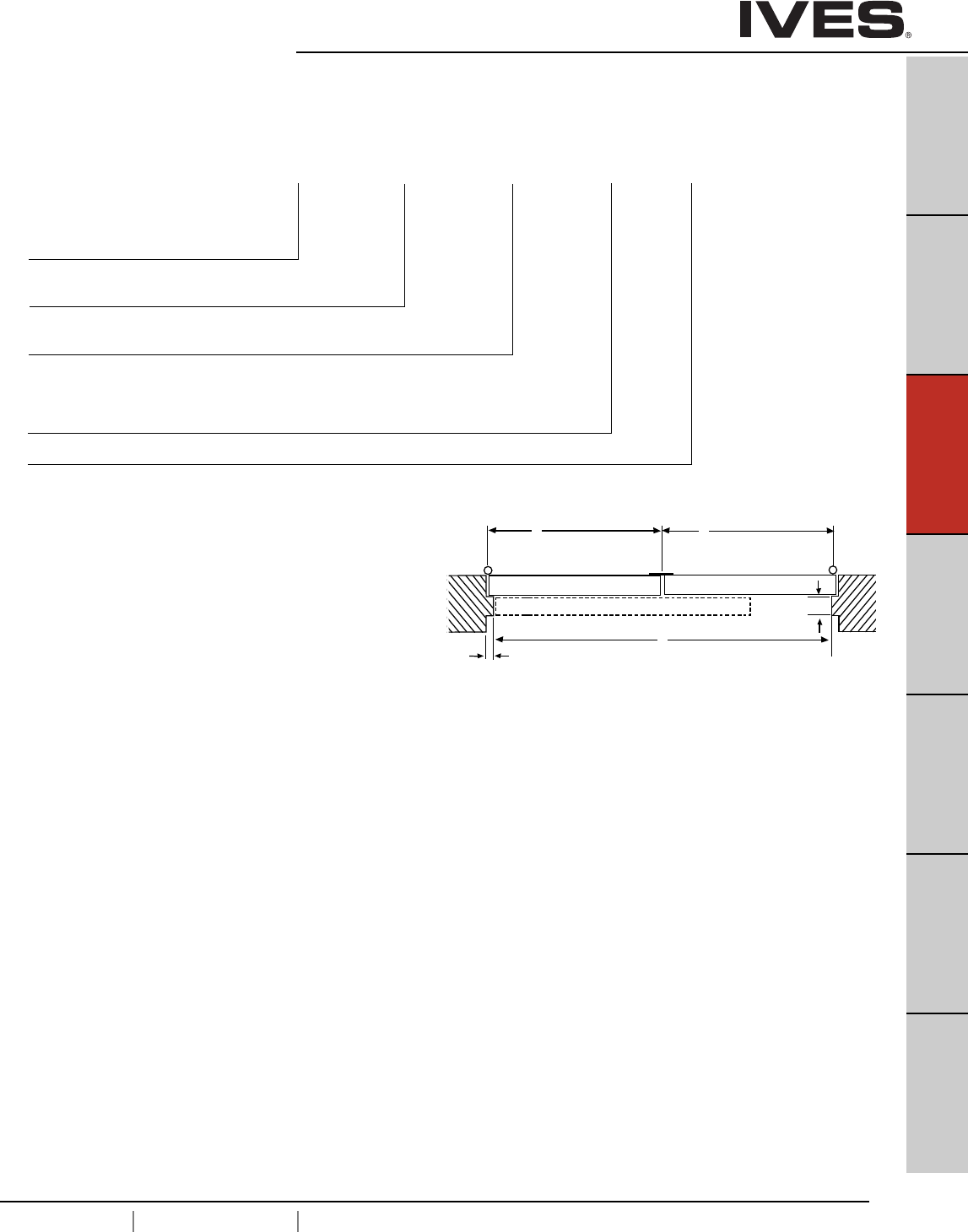
C15
USA 1.877.671.7011 Canada 1.905.403.1800 www.ives.ingersollrand.com
Ordering Guide – Bar Coordinators
B
Pulls & Plates
A
Hinges & Pivots
C15
Flush Bolts & Coordinators
D
Latches, Catches & Bolts
E
Stops
F
Exterior Hardware
G
Miscellaneous Hardware
To determine the size COR you need:
1. Start with the active door width (X).
2. Next consider the overall frame opening between stops (F).
3. Preferably, the coordinator would equal the active door
width (X) + approximately 1/2 inactive door width (Y).
The coordinator must be 6" longer than the active door width (X)
and less than the overall frame opening between stop (F).
Examples:
• Pair of 30" Doors, 5/8" Stops
Active Door Size, X = 30"
Overall Frame Opening between Stops, F = 58-3/4"
Recommended Coordinator: COR42
• Pair of 36" Doors, 5/8" Stops
Active Door Size, X = 36"
Overall Frame Opening between Stops, F = 70-3/4"
Recommended Coordinator: COR52
COORDINATOR
ACTIVE LEAF INACTIVE LEAF
ACTIVE DOOR
WIDTH
INACTIVE DOOR
WIDTH
XY
W
V
STOP THICKNESS
STOP WIDTH
F
COR 52 US28 FL20 D 36"
__ - ____ - ____ - __ - __
How to Order COR and Accessories
COR Size:
32, 42, 52, 60, 72
Finishes:
US28, US26D, 315AN
Filler Bar (if desired):
FL20, FL32, FL44
Vertical Rod Exit Device Cutout Type (if applicable):
A, B, C, D, E, F, G
If other Vertical Rod Exit Device not listed on chart, from page C16,
include information as shown on page C16.
Active Door Size – Required for ALL Vertical Rod Exit Device Applications
• 36" Active Door, 18" Inactive door, 5/8" Stops
Active Door Size, X = 36"
Overall Frame Opening between Stops, F = 52-3/4"
Recommended Coordinator: COR42
• 48" Active Door, 24" Inactive Door, 5/8" Stops
Active Door Size, X = 48"
Overall Frame Opening between Stops, F = 94-3/4"
Recommended Coordinator: COR60
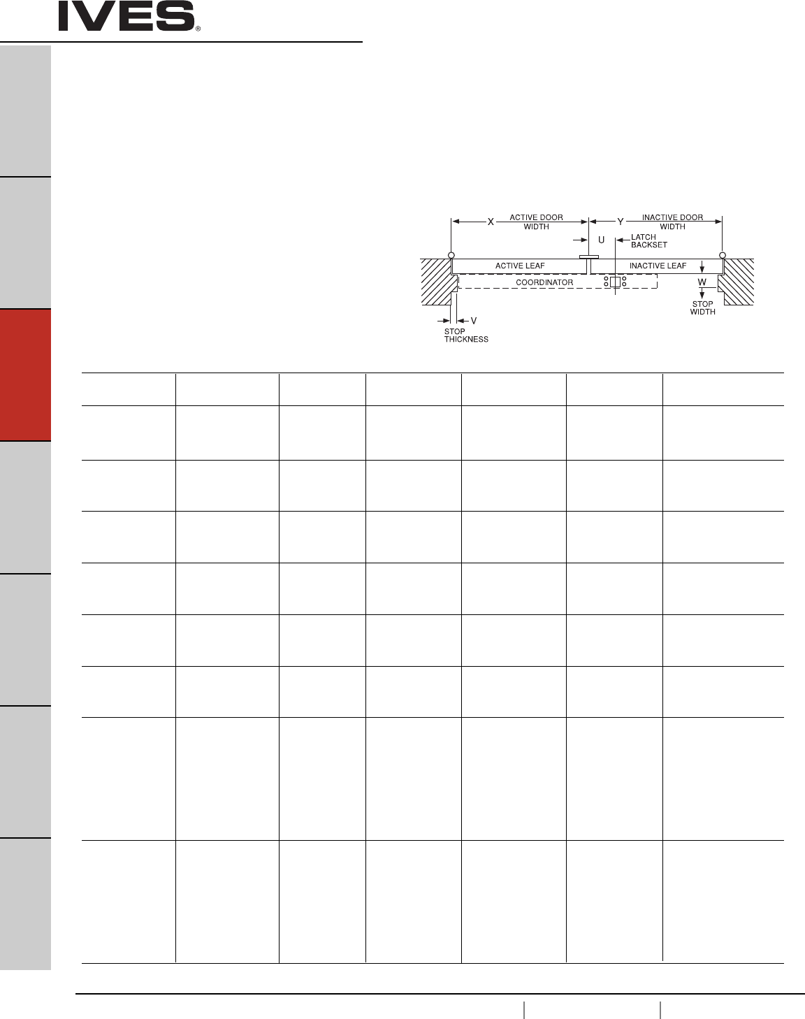
C16
USA 1.877.671.7011 Canada 1.905.403.1800 www.ives.ingersollrand.com
Coordinators
B
Pulls & Plates
A
Hinges & Pivots
C16
Flush Bolts & Coordinators
D
Latches, Catches & Bolts
E
Stops
F
Exterior Hardware
G
Miscellaneous Hardware
Exit Device Exit Device Device Maximum Coordinator Coordinator Mounting Bracket
Manufacturer Number Backset Active Door Size Needed Cutout Type Needed
33" 42"
Von Duprin 5547-F 2-3/8" 43" 52" Type A None
51" 60"
63" 72"
33" 42" MB1V, MB2V
Von Duprin 8827-F 2-3/4" 43" 52" Type B or MB3V
51" 60" see page C3
63" 72"
33" 42"
Von Duprin 8847-F 2-3/8" 43" 52" Type C None
51" 60"
63" 72"
33/3547 33" 42"
Von Duprin 33/3547-F 2-3/4" 43" 52" Type D None
98/9947 51" 60"
98/9947-F 64" 72"
33/3548 33" 42"
Von Duprin 33/3548-F 2-3/4" 43" 52" Type D None
98/9948 51" 60"
98/9948-F 64" 72"
33/3547WDC 34" 42"
Von Duprin 33/3547WDC-F 1-5/16" 44" 52" Type E None
98/9947WDC 52" 60"
98/9947WDC-F 65" 72"
17-C
F-17-C
18-C
F-18-C 33" 42"
Monarch XX-C 2-3/4" 43" 52" Type F None
F-XX-C 51" 60"
24-C 63" 72"
F-24-C
25-C
F-25-C
17-C-WDC
F-17-C-WDC
18-C-WDC
F-18-C-WDC 33" 42"
Monarch XX-C-WDC 2-13/16" 43" 52" Type G None
F-XX-C-WDC 51" 60"
24-C-WDC 63" 72"
F-24-C-WDC
25-C-WDC
F-25-C-WDC
Special Factory Preparation for
Use with Vertical Rod Exit Devices
Coordinators may need to be prepared at the factory for use with
some surface or concealed vertical rod exit devices.
(See Chart below)
1. Exit Device Manufacturer and Model No.
2. Active Door Size, “X”
3. Inactive Door Size, “Y”
4. Exit Device Backset, “U”
5. Stop Width, “W”
6. Stop Thickness if other than 5/8", “V”
If the exit device is not listed the following information is needed.
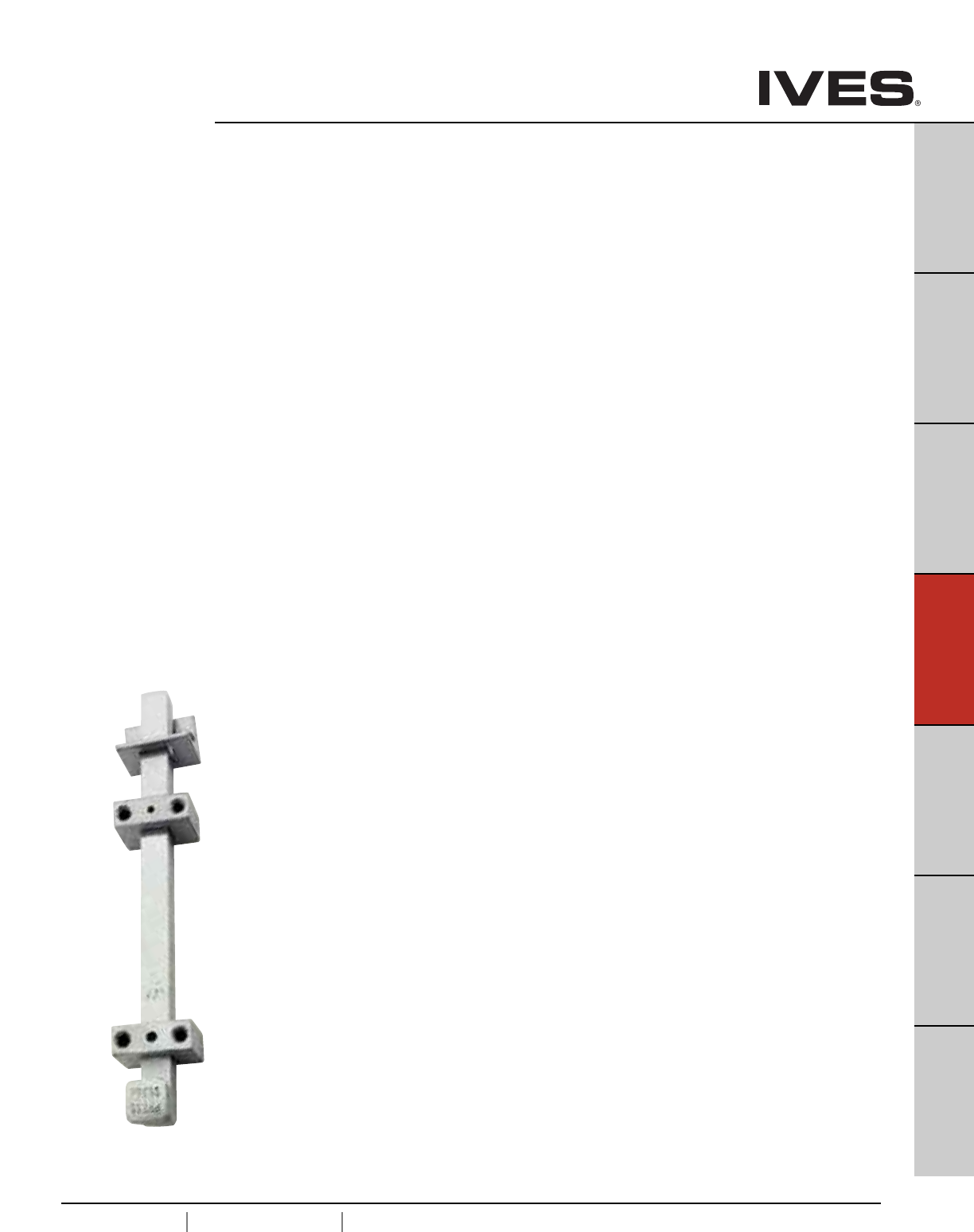
D1
USA 1.877.671.7011 Canada 1.905.403.1800 www.ives.ingersollrand.com
Surface Bolts, Latches & Catches
B
Pulls & Plates
A
Hinges & Pivots
C
Flush Bolts & Coordinators
D1
Latches, Catches & Bolts
E
Stops
F
Exterior Hardware
G
Miscellaneous Hardware
Table Of Contents
Surface Bolts page
SB360 Surface Bolt . . . . . . . . . . . . . . . . . . . . . . . . . . . . . . . . . . . . . . . . . . . . . . . . . .D2
SB453 Surface Bolt . . . . . . . . . . . . . . . . . . . . . . . . . . . . . . . . . . . . . . . . . . . . . . . . . .D2
SB1600 Surface Bolt . . . . . . . . . . . . . . . . . . . . . . . . . . . . . . . . . . . . . . . . . . . . . . . . .D3
SB1601M1 Surface Bolt . . . . . . . . . . . . . . . . . . . . . . . . . . . . . . . . . . . . . . . . . . . . . .D3
SB1601M2 Surface Bolt . . . . . . . . . . . . . . . . . . . . . . . . . . . . . . . . . . . . . . . . . . . . . .D3
40 Surface Bolt, Decorative . . . . . . . . . . . . . . . . . . . . . . . . . . . . . . . . . . . . . . . . . . . .D4
253 Surface Bolt, Decorative . . . . . . . . . . . . . . . . . . . . . . . . . . . . . . . . . . . . . . . . . . .D5
S48 Mortise Door Bolt . . . . . . . . . . . . . . . . . . . . . . . . . . . . . . . . . . . . . . . . . . . . . . .D6
054 Dutch Door Bolt . . . . . . . . . . . . . . . . . . . . . . . . . . . . . . . . . . . . . . . . . . . . . . . . .D6
Door Guards
481 Chain Door Guard . . . . . . . . . . . . . . . . . . . . . . . . . . . . . . . . . . . . . . . . . . . . . . .D7
482 Solid Bar Door Guard . . . . . . . . . . . . . . . . . . . . . . . . . . . . . . . . . . . . . . . . . . . . .D7
Roller Latch
RL30 Roller Latch . . . . . . . . . . . . . . . . . . . . . . . . . . . . . . . . . . . . . . . . . . . . . . . . . . .D8
RL32 Roller Latch . . . . . . . . . . . . . . . . . . . . . . . . . . . . . . . . . . . . . . . . . . . . . . . . . . .D8
RL36 Roller Latch . . . . . . . . . . . . . . . . . . . . . . . . . . . . . . . . . . . . . . . . . . . . . . . . . . .D9
RL38 Roller Latch . . . . . . . . . . . . . . . . . . . . . . . . . . . . . . . . . . . . . . . . . . . . . . . . . . .D9
RL1152 Roller Latch . . . . . . . . . . . . . . . . . . . . . . . . . . . . . . . . . . . . . . . . . . . . . . . .D10
STK685 Strike Plate . . . . . . . . . . . . . . . . . . . . . . . . . . . . . . . . . . . . . . . . . . . . . . . .D10
STK685L Strike Plate . . . . . . . . . . . . . . . . . . . . . . . . . . . . . . . . . . . . . . . . . . . . . . .D10
Angle Stop
AS18 Angle Stop . . . . . . . . . . . . . . . . . . . . . . . . . . . . . . . . . . . . . . . . . . . . . . . . . . .D11
AS895 Angle Stop . . . . . . . . . . . . . . . . . . . . . . . . . . . . . . . . . . . . . . . . . . . . . . . . . .D11
Latches/Catches
CL11 Invisible Latch . . . . . . . . . . . . . . . . . . . . . . . . . . . . . . . . . . . . . . . . . . . . . . . .D12
CL12 Invisible Latch . . . . . . . . . . . . . . . . . . . . . . . . . . . . . . . . . . . . . . . . . . . . . . . .D12
CL14 Auxiliary Pusher . . . . . . . . . . . . . . . . . . . . . . . . . . . . . . . . . . . . . . . . . . . . . . .D12
CL21 Ball Catch . . . . . . . . . . . . . . . . . . . . . . . . . . . . . . . . . . . . . . . . . . . . . . . . . . . .D13
CL21A Ball Catch . . . . . . . . . . . . . . . . . . . . . . . . . . . . . . . . . . . . . . . . . . . . . . . . . .D13
CL22 Ball Catch . . . . . . . . . . . . . . . . . . . . . . . . . . . . . . . . . . . . . . . . . . . . . . . . . . . .D13
325 Magnetic Catch . . . . . . . . . . . . . . . . . . . . . . . . . . . . . . . . . . . . . . . . . . . . . . . .D14
326 Magnetic Catch, Heavy Duty . . . . . . . . . . . . . . . . . . . . . . . . . . . . . . . . . . . . . .D14
327 Magnetic Catch, Heavy Duty . . . . . . . . . . . . . . . . . . . . . . . . . . . . . . . . . . . . . .D14
330 Roller Catch . . . . . . . . . . . . . . . . . . . . . . . . . . . . . . . . . . . . . . . . . . . . . . . . . . .D15
335 Roller Catch . . . . . . . . . . . . . . . . . . . . . . . . . . . . . . . . . . . . . . . . . . . . . . . . . . .D15
336 Roller Catch . . . . . . . . . . . . . . . . . . . . . . . . . . . . . . . . . . . . . . . . . . . . . . . . . . .D15
345 Ball Catch, Adjustable . . . . . . . . . . . . . . . . . . . . . . . . . . . . . . . . . . . . . . . . . . .D16
347 Ball Catch, Dual Adjustable . . . . . . . . . . . . . . . . . . . . . . . . . . . . . . . . . . . . . . .D16
349 Ball Catch . . . . . . . . . . . . . . . . . . . . . . . . . . . . . . . . . . . . . . . . . . . . . . . . . . . . .D16
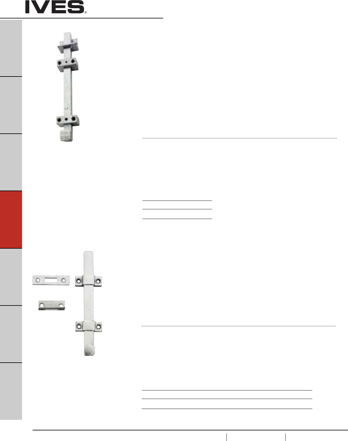
D2
USA 1.877.671.7011 Canada 1.905.403.1800 www.ives.ingersollrand.com
Surface Bolts
B
Pulls & Plates
A
Hinges & Pivots
C
Flush Bolts & Coordinators
D2
Latches, Catches & Bolts
E
Stops
F
Exterior Hardware
G
Miscellaneous Hardware
SB360 Surface Bolt
•Surface Bolt has 1-1/4" throw for maximum security.
• Jimmy-resistant design, bolt locks automatically when thrown,
can be released only be pressing knob toward door while retracting.
• Ideal for all types of doors.
• Available in 12" length
• Unit locks in both the up and down position.
• Accepts padlock (not furnished) with maximum 3/8" diameter shackle,
minimum 1-3/4" shackle opening height.
• Units packed with one-way screws for added security.
Standard screws also supplied.
• Units packed with both a universal top strike (US) and a mortise bottom
strike (MS).
• Constructed of heavy duty steel.
• Optional Sex Bolts available.
• Optional Mortise Strike available.
Dimensions
Bar: 3/4" Wide x 3/4" Thick
Overall Width: 2-1/32"
Overall Projection: 2-1/16"
Top Strike: 1-1/2" Wide x 1-1/2" Long x 3/16" Thick
Optional Mortise Strike: 1-5/8" Wide x 3-1/2" Long x 1/8" Thick
SB453 Surface Bolt
• Surface Bolt has 1-3/16" throw for maximum security.
• Strong tension springs prevent creep.
• Ideal for all types of doors.
• Available 8" & 12" lengths.
• Units packed with standard screws for added security.
• Units packed with both a universal top strike (US) and
a mortise bottom strike (MS).
• Constructed of heavy duty steel.
• Optional Sex Bolts available.
• Optional Thru Bolts available.
Dimensions
Bar: 3/4" Wide x 1/4" Thick
Overall Width: 2-1/32"
Overall Projection: 1-5/16"
Top Strike: 1-1/2" Wide x 1-1/2" Long x 3/16" Thick
Bottom Strike: 1-5/8" Wide x 3-1/2" Long x 1/8" Thick
Finishes
Ives Number US2C
BHMA 603
Meets ANSI/BHMA A 156.16
UL listed 3 hour fire door, up to 10'0"
Miami Dade County NOA Listed
Meets ANSI/BHMA A156.16 L84161
UL listed 3 hour fire door, up to 10'0"
Finishes
Ives Number US2C US3 US4* US10 US10B US26D
BHMA 603 632 633 639 640 652
* only available in 8” bolt length.
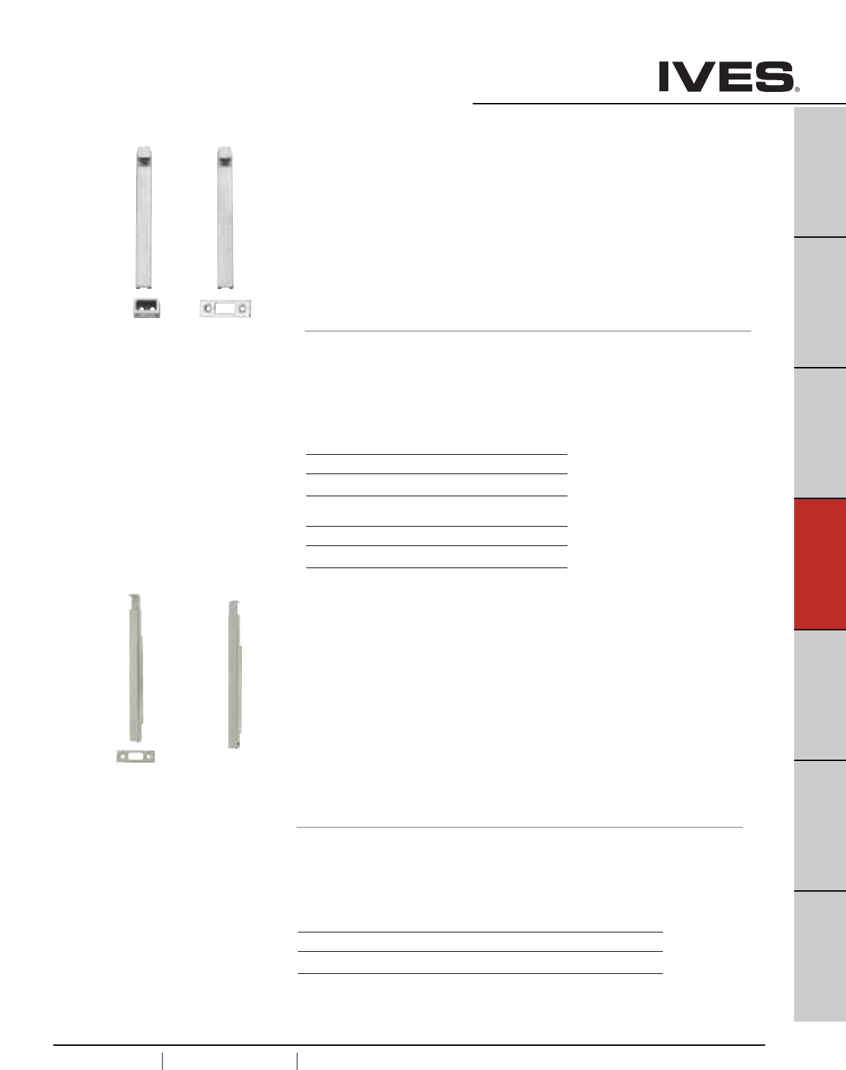
D3
USA 1.877.671.7011 Canada 1.905.403.1800 www.ives.ingersollrand.com
Surface Bolts
B
Pulls & Plates
A
Hinges & Pivots
C
Flush Bolts & Coordinators
D3
Latches, Catches & Bolts
E
Stops
F
Exterior Hardware
G
Miscellaneous Hardware
SB1600 Surface Bolt
• Standard Surface Bolt has 1" throw for maximum security.
• Ideal for all types of doors.
• Fully concealed mounting prevents vandalism.
• Available in locking version. Unit locks in both the up and down
position. Locking Bolts are furnished with 2 keys in 4 keying variations.
• Units packed with wood and machine screws to meet most field conditions.
• Units available with either a universal top strike (T) or a flat bottom strike (B).
• 1630 Series is constructed of heavy duty steel.
• 1640 Series is constructed of brass.
• Optional sex bolts available
Dimensions
Body: 8" Long x 7/8" Wide x 3/4" Thick,
Overall Knob or Lock Housing Projection: 1-1/2"
Top Strike: 1-1/4" Wide x 7/8" Tall x 15/16" Deep
Bottom Strike: 3" Long x 1" Wide x 1/8" Thick
SB1630 Finishes steel
Ives Number US2G US10B US26D
BHMA 604 640 652
SB1640 Finishes brass
Ives Number US3 US10B US26D
BHMA 605 613 626
1630 meets ANSI/BHMA A156.16, L84161 and
UL listed 3 hour fire doors up to 8'0" in height.
1640 meets ANSI/BHMA A156.16, L24161.
SB1600M1
SB1600M2 Surface Bolt
• Standard Surface Bolt has 3-1/2" throw for maximum security and for doors
with larger undercuts.
• Sleek handle design.
• Ideal for all types of doors.
• Fully concealed mounting prevents vandalism.
• Available in locking version. Unit locks in both the up and down position.
Locking bolts are furnished with 2 keys in 4 keying variations.
• Units packed with wood and machine screws to meet most field conditions.
• Units available with either a universal top strike (T) or a flat bottom strike (B).
• Constructed of heavy duty steel.
• Optional sex bolts available
Dimensions
Bar: 11" Long x 3/4" Wide x 3/4" Thick, locking version 1-1/2" Thick
Top Strike: 1-1/4" Wide x 7/8" Tall x 15/16" Deep
Bottom Strike: 3" Long x 1" Wide x 1/8" Thick
Finishes
Ives Number SP4 SP10 SP28 SP313 SPBLK
BHMA 706 691 689 695 622
UL listed 3 hour fire doors up to 8'0" in height.
SB1600M1 SB1600M2
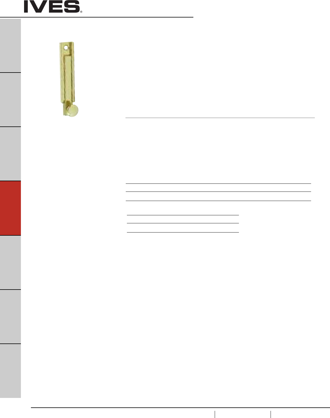
D4
USA 1.877.671.7011 Canada 1.905.403.1800 www.ives.ingersollrand.com
Decorative Surface Bolts
B
Pulls & Plates
A
Hinges & Pivots
C
Flush Bolts & Coordinators
D4
Latches, Catches & Bolts
E
Stops
F
Exterior Hardware
G
Miscellaneous Hardware
40 Decorative Surface Bolt
• Concealed screw design enhances appearance and security.
• Exceptional strength and durability provided by interlocking
construction of heavy gauge track and rod.
• Permanent stop prevents rod disengagement from track.
• Tension spring holds bolt in desired position.
• Track assures smooth operation and interlocks with side edges of
rod to eliminate marring.
• Decorative 5/8" diameter knob designed to facilitate bolt operation.
• Made from extruded brass or aluminum.
• Available in 3", 4" and 6" lengths.
• Packed with both Universal and Mortise Strikes.
Optional Surface Strike available.
Dimensions
Throw: 15/16"
Projection: 3/4"
Width: 11/16"
Length: 3", 4" or 6"
Meets ANSI/BHMA A156.16
Finishes brass
Ives Number B3 B5 B10B B15 B26 B26D
BHMA 605 609 613 619 625 626
Finishes aluminum
Ives Number A3* A15* PA28 A716*
BHMA 666 670 628
* only available 3” bolt Schlage Carded.
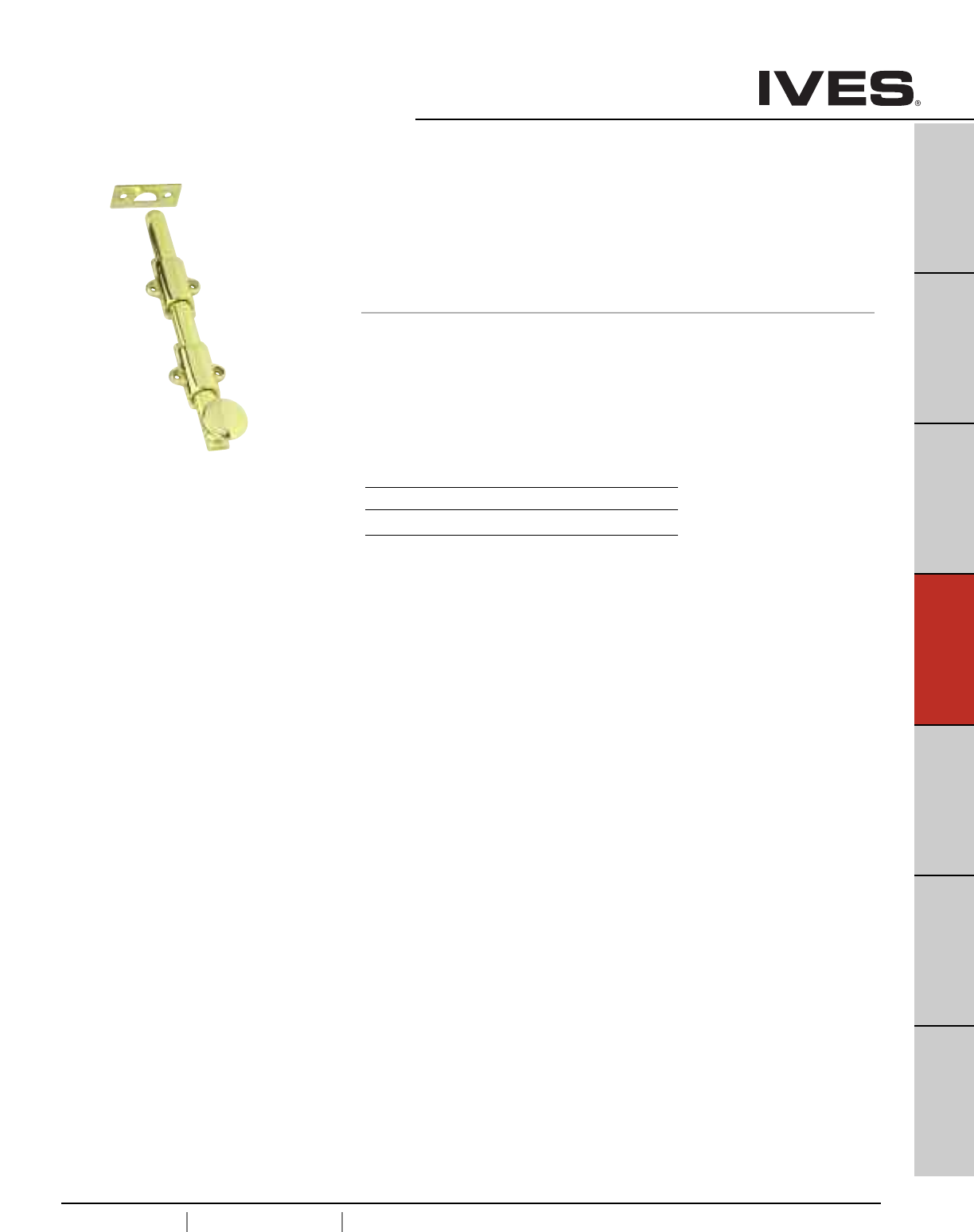
D5
USA 1.877.671.7011 Canada 1.905.403.1800 www.ives.ingersollrand.com
Decorative Surface Bolts
B
Pulls & Plates
A
Hinges & Pivots
C
Flush Bolts & Coordinators
D5
Latches, Catches & Bolts
E
Stops
F
Exterior Hardware
G
Miscellaneous Hardware
253 Decorative Surface Bolt
• Heavy duty, decorative bolt ideal where extra strength required
• Decorative 1-1/4" diameter knob fits well with any décor and
designed to facilitate bolt operation.
• Made from solid brass.
• Available in 8" and 12" lengths.
• Packed Universal Strike (US) & Mortise Strike (MS).
Dimensions
Throw: 1-1/8"
Projection: 1-5/16"
Half Round Rod: 5/8"
Overall Width: 1-5/8"
Length: 8" or 12"
Meets ANSI/BHMA A156.16 Finishes
Ives Number B3 B10B B26D
BHMA 605 613 626
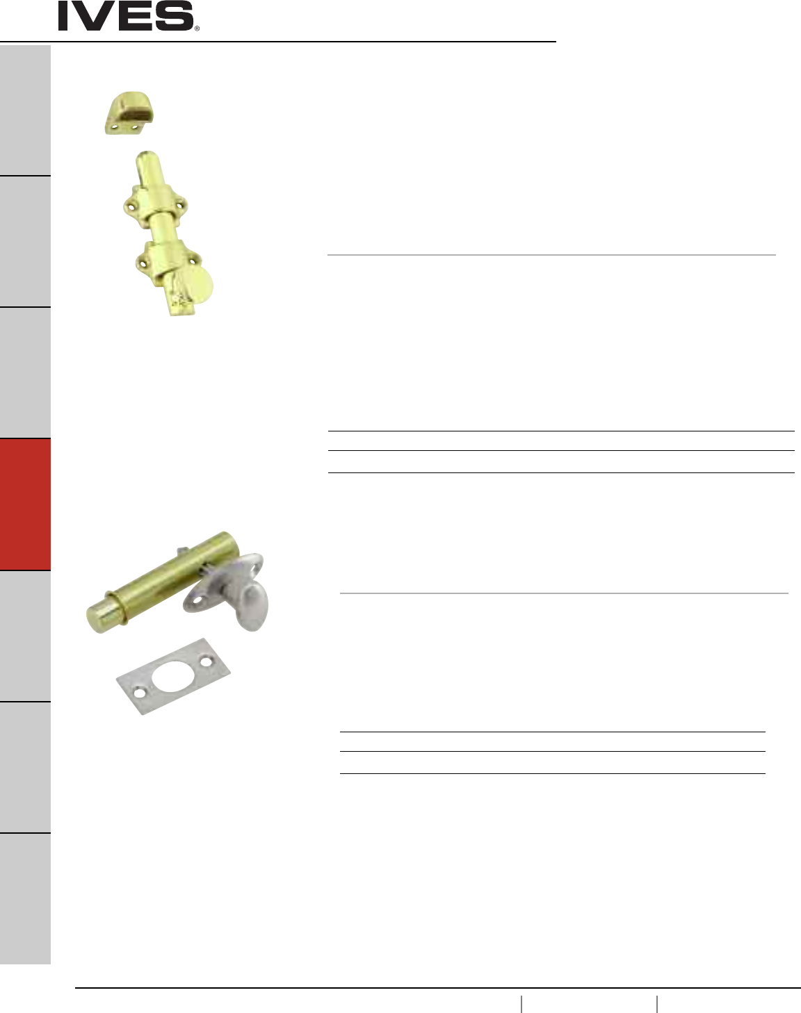
D6
USA 1.877.671.7011 Canada 1.905.403.1800 www.ives.ingersollrand.com
Dutch Door & Mortise Door Bolts
B
Pulls & Plates
A
Hinges & Pivots
C
Flush Bolts & Coordinators
D6
Latches, Catches & Bolts
E
Stops
F
Exterior Hardware
G
Miscellaneous Hardware
054 Dutch Door Bolt
•Practical, rugged, attractive bolt for application on dutch doors
as well as other areas.
• Chamfered rod end draws the two leaves of door tightly together.
• Sufficient tolerance provided in strike opening to allow for misalignment
of door leaves and also prevents binding of bolt.
• Decorative 1" diameter knob designed to facilitate bolt operation.
• Made from solid brass.
• Packed with Standard Strike (SS), Mortise Strike (MS) and
Universal Strike (US).
Dimensions
Throw: 5/8"
Projection: 1-1/8"
Half Round Rod: 5/8"
Overall Width: 1-5/8"
Rod Length: 4-1/4"
Overall Length: Specify 4-3/8" (Including Knob)
Finishes
Ives Number B3 B4 B10 B10B B15 B26 B26D
BHMA 605 606 612 613 619 625 626
Finishes brass
Ives Number B3 B5 B10B B15 B26 B26D
BHMA 605 609 613 619 625 626
S48 Mortise Door Bolt
• Brass oval turn knob and escutcheon.
• Steel bolt for extra strength.
Rack is milled for precision fit with pinion.
Dimensions
Backset: 1-3/4"
Bolt Throw: 1/2"
Bolt Diameter: 1/2"
Case: 2-1/2" Long x 9/16" diameter
Strike: 1-3/4" High x 7/8" Wide
Meets ANSI/BHMA A156.16.
Meets ANSI/BHMA A156.16.
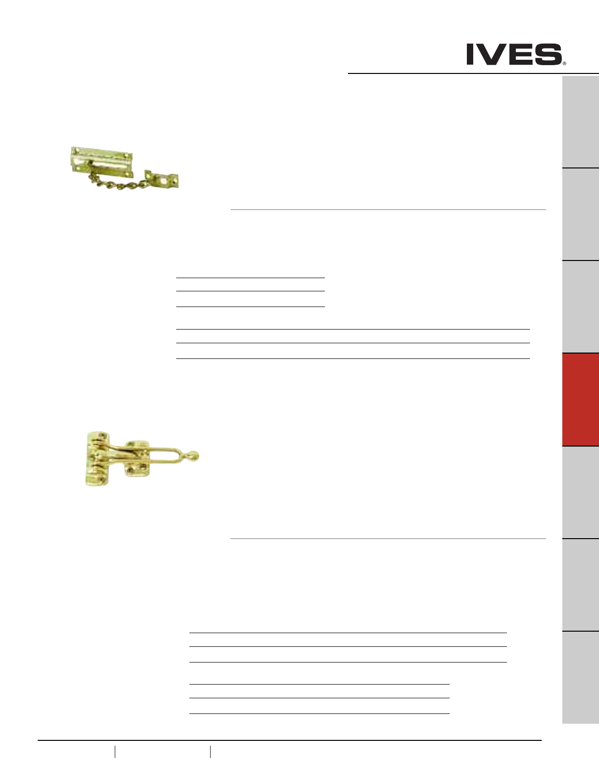
D7
USA 1.877.671.7011 Canada 1.905.403.1800 www.ives.ingersollrand.com
Door Guards
B
Pulls & Plates
A
Hinges & Pivots
C
Flush Bolts & Coordinators
D7
Latches, Catches & Bolts
E
Stops
F
Exterior Hardware
G
Miscellaneous Hardware
481 Chain Door Guard
• Permits the door to be slightly opened to allow viewing.
• Narrow chain holder maintains chain in stationary position when
door guard is not in use, eliminating marring of door and
frame caused by dangling chain.
• Welded twist link steel chain finished to match door plate
and chain holder.
• Made from wrought brass or burnished wrought steel.
• Packed with sheet metal screws.
Dimensions
Door Plate: 3-3/8" Long x 1-7/16" Wide
Chain Holder: 1-10/16" High x 3/4" Wide
Chain Length: 4-3/4"
482 Solid Bar Door Guard
• For use on doors that are flush with frames.
• The solid bar, interlocking with the ball on the strike plate,
permits the door to be slightly opened to allow viewing.
• The hinged bar allows the door guard to be positioned 180° away
from the door when not in use.
• Edge guard only, furnished with cast brass door guards,
minimizes the chance for marring the door or frame.
• Strike plate is designed to prevent the solid bar from marring the
inside of the door when in use.
• Made from cast brass or cast aluminum.
• Packed with sheet metal screws.
• Shims available in US26D (626) only, 1/8” or 3/8”.
Cast Brass Dimensions Cast Aluminum Dimensions
Strike Plate: 2-5/8" High x 1-1/32" Wide Strike Plate: 2-1/2" High x 7/8" Wide
Holder: 1-3/4" High x 1-1/16" Wide Holder: 2-1/2" High x 15/16" Wide
Arm Length: 4-3/4" Arm Length: 3-13/16"
Edge Guard: 1-1/8" High x 1-1/32" Wide
Meets ANSI/BHMA A156.16
Meets ANSI/BHMA A156.16
Finishes brass
Ives Number B3 B26D
BHMA 605 626
Finishes steel
Ives Number F3 F4 F5 F10 F15 F26 F26D F716
BHMA 632 633 638 639 646 651 652
Finishes brass
Ives Number B3 B4 B10 B10B B15 B26 B26D
BHMA 605 606 612 613 619 625 626
Finishes aluminum
Ives Number A3 A5 A26 A26D
BHMA 666 672 702
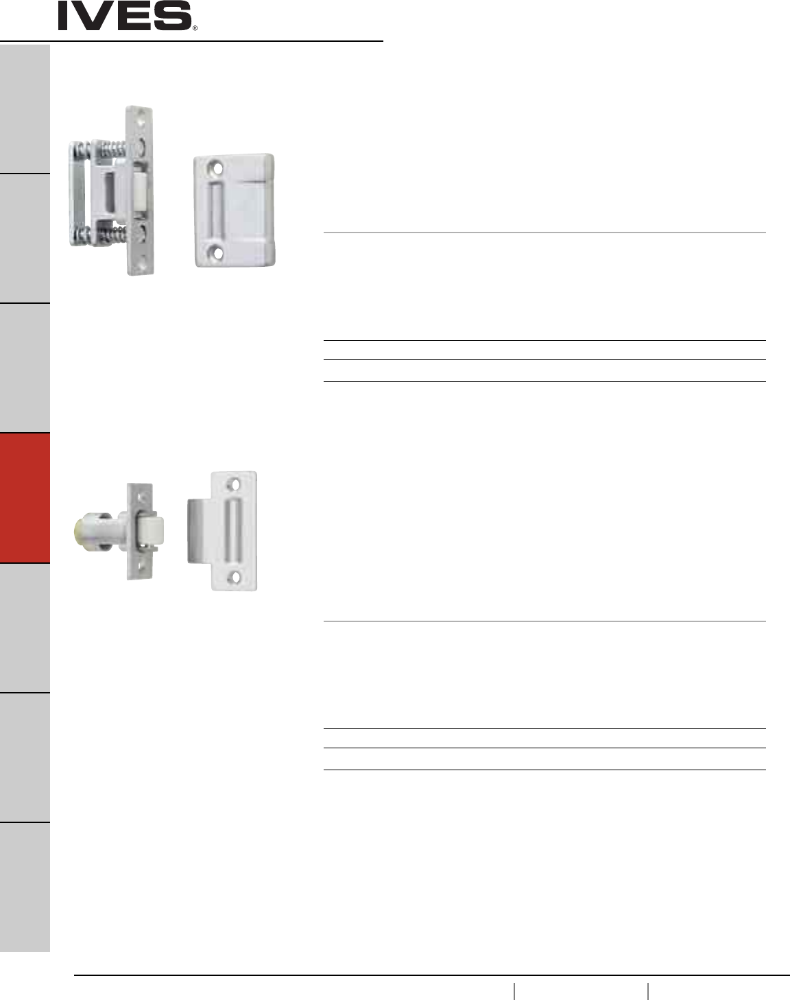
D8
USA 1.877.671.7011 Canada 1.905.403.1800 www.ives.ingersollrand.com
B
Pulls & Plates
A
Hinges & Pivots
C
Flush Bolts & Coordinators
D8
Latches, Catches & Bolts
E
Stops
F
Exterior Hardware
G
Miscellaneous Hardware
Roller Latches
RL30 Roller Latch
• Actuation is simple, closing of the door causes the roller to fall in the
depression of the strike, thereby holding the door closed.
• The projection of the roller is easily adjusted using adjusting screws
on the face of the unit.
• Maximum projection of the roller is 3/8" allowing for variance in
the door clearance.
• Nylon Roller Standard.
• Forged Brass Construction.
• Optional Strike—A—ASA.
• Optional— F — Brass Roller, must be ordered separately.
Dimensions
Body: 1" Wide x 3-3/8" High x 1-11/16" Deep
Strike: 1-11/16" Wide x 2-1/4" High x 5/32" Thick, Lip to Center- 1-5/16"
Optional ASAStrike:1-1/4" Wide x 4-7/8" High x 3/32" Thick, Lip to Center- 1-1/4"
RL32 Roller Latch
• Actuation is simple, closing of the door causes the roller to fall
in the depression of the strike, thereby holding the door closed.
• The projection of the roller is easily adjusted by turning knurled
knob on back of latch.
• Maximum projection of the roller is 1/2" allowing for variance in
the door clearance.
• Fits heavy-duty cylindrical lock cutout.
• Nylon Roller Standard.
• Non-handed.
• Brass Construction.
• Optional Strike—A—ASA.
Dimensions
Body: 1-1/8" Wide x 2-1/4" High x 2-1/4" Deep
Strike: 1-1/8" Wide x 2-3/4" High x 3/32" Thick, Lip to Center- 1-1/4"
Optional ASA Strike: 1-1/4" Wide x 4-7/8" High x 3/32" Thick, Lip to Center- 1-1/4"
Meets ANSI/BHMA A156.16, E19091
Meets ANSI/BHMA A156.16, E19091
Finishes brass
Ives Number US3 US4 US10 US10B US26 US26D
BHMA 605 606 612 613 625 626
Finishes brass
Ives Number US3 US4 US10 US10B US26 US26D
BHMA 605 606 612 613 625 626
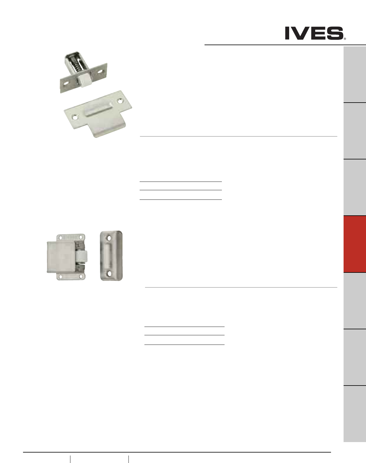
D9
USA 1.877.671.7011 Canada 1.905.403.1800 www.ives.ingersollrand.com
B
Pulls & Plates
A
Hinges & Pivots
C
Flush Bolts & Coordinators
D9
Latches, Catches & Bolts
E
Stops
F
Exterior Hardware
G
Miscellaneous Hardware
Roller Latches
RL36 Roller Latch
• Actuation is simple, closing of the door causes the roller to fall in
the depression of the strike, thereby holding the door closed.
• The projection of the roller is easily adjusted by turning slotted
screw on back of latch.
• Maximum projection of the roller is 5/16" allowing for variance
in the door clearance.
• Fits cylindrical lock cutout.
• Nylon Roller.
• Non-handed.
• Stainless Steel Construction.
• Optional Strike–A—ASA.
Dimensions
Body: 1" Wide x 2-1/4" High x 2" Deep
Strike: 1-1/8" Wide x 2-3/4" High x 3/32" Thick, Lip to Center- 1-1/4"
Optional ASA Strike: 1-1/4" Wide x 4-7/8" High x 3/32" Thick, Lip to Center- 1-1/4"
Meets ANSI/BHMA A156.16, L57082
Meets ANSI/BHMA A156.16, L27092
Finishes Stainless Steel
Ives Number US32D
BHMA 630
RL38 Roller Latch
• Actuation is simple, closing of the door causes the roller to fall in the
depression of the strike, thereby holding the door closed.
• The projection of the roller is easily adjusted by turning slotted screw.
• Maximum projection of the roller is 3/8" allowing for variance in the
door clearance.
• Nylon Roller.
• Non-handed.
• Stainless Steel Construction.
Dimensions
Body: 1-3/8" Wide x 2"High x 7/8" Deep
Strike: 1" Wide x 2-1/8" High x 3/8"Deep
Finishes Stainless Steel
Ives Number US32D
BHMA 630
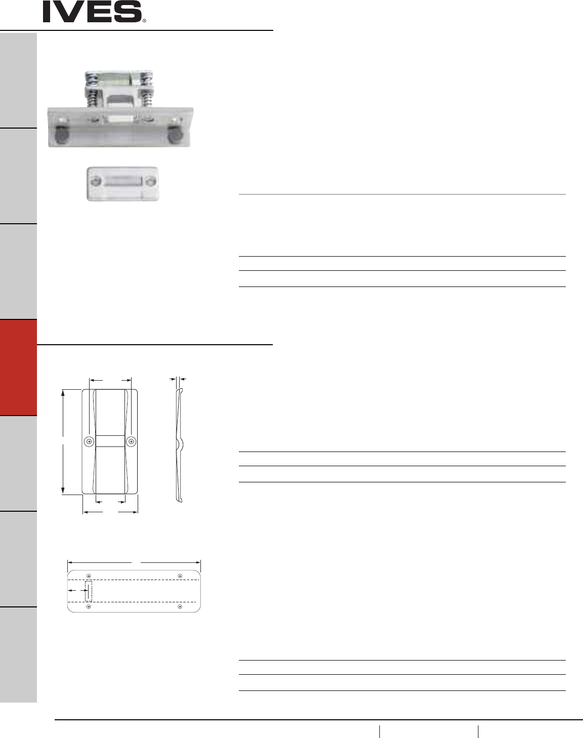
D10
USA 1.877.671.7011 Canada 1.905.403.1800 www.ives.ingersollrand.com
B
Pulls & Plates
A
Hinges & Pivots
C
Flush Bolts & Coordinators
D10
Latches, Catches & Bolts
E
Stops
F
Exterior Hardware
G
Miscellaneous Hardware
Roller Latches
RL1152 Roller Latch
• Combination of RL30 Roller Latch and Angle Stop.
• Actuation is simple, closing of the door causes the roller to
fall in the depression of the strike, thereby holding the
door closed.
• The projection of the roller is easily adjustable using
adjusting screws on the face of the unit.
• Maximum projection of the roller is 3/8" allowing for
variance in the door clearance.
• Nylon Roller Standard.
• Forged Brass Construction.
• Optional— F — Brass Roller, must be ordered separately.
Dimensions
Body: 1-1/2"Wide x 4-1/2" High x 1-3/4" Deep with 3/4" Angle
Strike: 1-1/8" Wide x 2-1/4" High x 5/32"Thick
Optional Strike
STK685 Strike
• Custom make strike for doors that swing both directions.
For use with roller latches.
• Constructed of 3/32" brass.
• Dimple of strike centered on strike.
• Specify frame depth - A. Overall strike length will be
A + 3/8” to accomodate 3/16” lip on each side
A
1-11/16"
1-5/32"
2-1/4"
3/32"
A
B
STK685L Strike
• Custom make strike for doors that swing both directions.
For use with roller latches.
• Constructed of 3/32" brass.
• Location of strike dimple is variable.
Please specify frame depth - A and location of dimple
from edge of frame - B. Dimple will be located B + 3/16"
to accomodate lip.
• Specify frame depth - A. Overall strike length will be
A + 3/8” to accomodate 3/16” lip on each side
Finishes
Ives Number US3 US4 US10 US10B US26 US26D
BHMA 605 606 612 613 625 626
Finishes
Ives Number US3 US4 US10 US10B US26 US26D
BHMA 605 606 612 613 625 626
Finishes
Ives Number US3 US4 US10 US10B US26 US26D
BHMA 605 606 612 613 625 626
Meets ANSI/BHMA A156.16, E19111
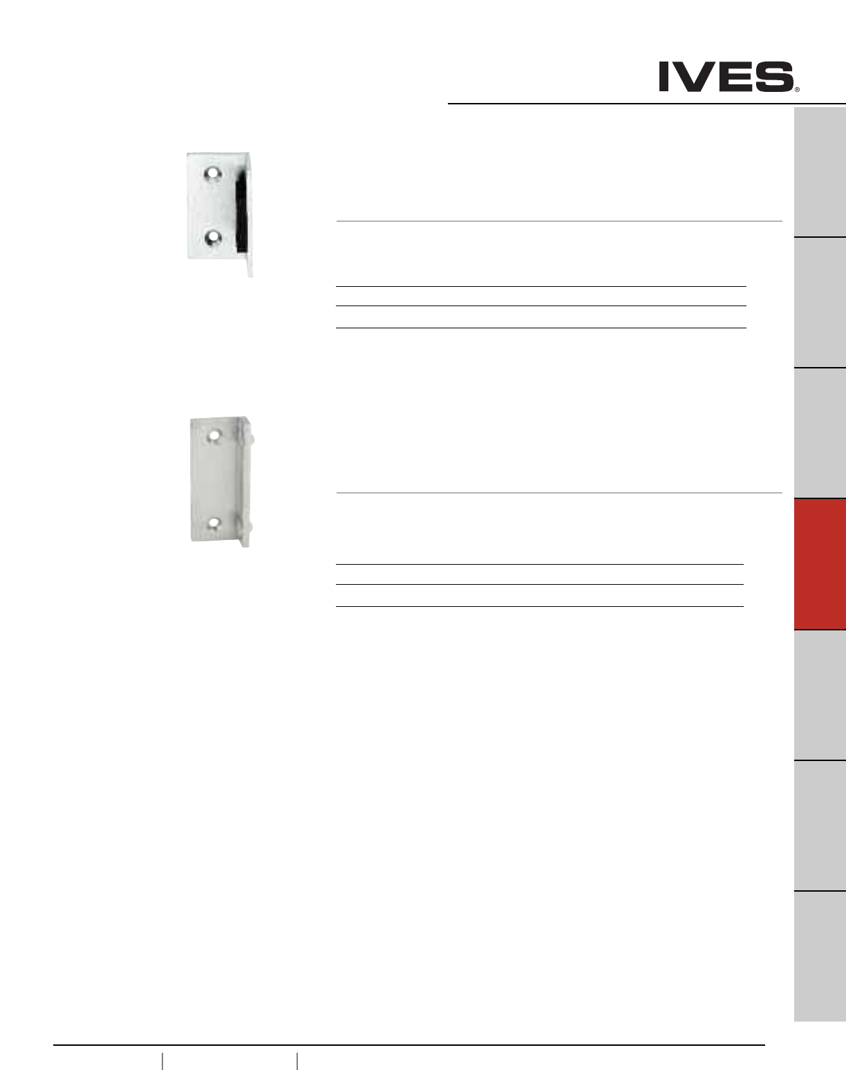
D11
USA 1.877.671.7011 Canada 1.905.403.1800 www.ives.ingersollrand.com
B
Pulls & Plates
A
Hinges & Pivots
C
Flush Bolts & Coordinators
D11
Latches, Catches & Bolts
E
Stops
F
Exterior Hardware
G
Miscellaneous Hardware
Angle Stops
AS895 Angle Stop
•Surface applied stop for single doors.
•Large rubber bumper to ensure quiet operation.
• Constructed of 1/8" Brass Angle.
Dimensions
1-1/2" Wide x 1" Angle x 2-1/2" Long
AS18 Angle Stop
• Surface applied stop for single and double doors.
• Includes SR64 door silencers to ensure quiet operation.
SR64 silencers are replaceable.
• Constructed of 3/16" Brass Angle.
Dimensions
1-1/2" Wide x 3/4" Angle x 3-1/2" Long
Finishes
Ives Number US3 US4 US10 US10B US26 US26D
BHMA 605 606 612 613 625 626
Finishes
Ives Number US3 US4 US10 US10B US26 US26D
BHMA 605 606 612 613 625 626
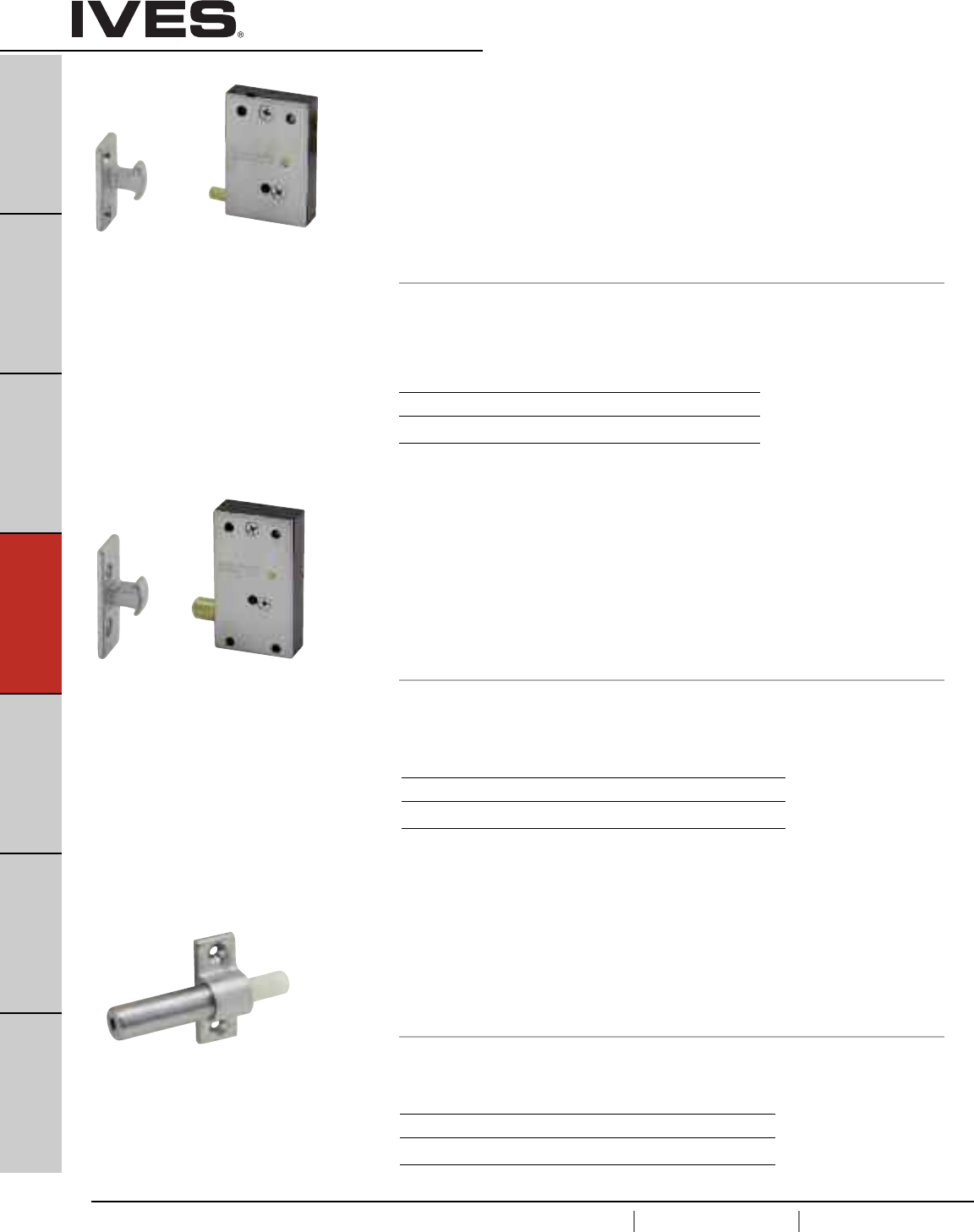
D12
USA 1.877.671.7011 Canada 1.905.403.1800 www.ives.ingersollrand.com
B
Pulls & Plates
A
Hinges & Pivots
C
Flush Bolts & Coordinators
D12
Latches, Catches & Bolts
E
Stops
F
Exterior Hardware
G
Miscellaneous Hardware
Invisible Latches
CL11 Invisible Latch
•Invisible latch is ideal for installations where no visible latch is desired.
•Unit can be installed at the top, bottom or side of the door.
•Can be mortised into the stop or surface mounted to the stop.
•Recommended for use on small panels, cabinet doors or light weight
closet doors.
• Operation is simple, latching is accomplished by a slight push.
To unlatch the door, a harder push releases the door and pushes the
door out.
• Brass and plastic construction.
• Applies 13 pounds to open the door.
Dimensions
Body: 1-1/4" Wide x 1-7/8" High x 7/16" Thick
Strike: 9/16" Wide x 1-5/16" High x 9/16" High
Meets ANSI/BHMA 156.9, B03272
Finishes
Ives Number US3 US4 US10 US26D
BHMA 605 606 612 626
Finishes
Ives Number US3 US4 US10 US26D
BHMA 605 606 612 626
Finishes
Ives Number US3 US4 US10 US26D
BHMA 605 606 612 626
CL12 Invisible Latch
• Invisible latch is ideal for installations where no visible latch is desired.
• Unit can be installed at the top, bottom or side of the door.
• Can be mortised into the stop or surface mounted to the stop.
• Recommended for use on larger panels or regular size doors.
• Operation is simple, latching is accomplished by a slight push.
To unlatch the door, a harder push releases the door and pushes the
door out.
• Brass and plastic construction.
• Applies 27 pounds to open the door.
Dimensions
Body: 1-1/4" Wide x 2-1/4" High x 9/16" Thick
Strike: 5/8" Wide x 1-13/16" High x 9/16" Projection
Meets ANSI/BHMA A156.9, B03272
CL14 Auxiliary Pusher
• Aid in the operation of the CL11 and CL12 where hinges or
surrounding conditions prevent smooth operation of doors.
• Provides 1-1/16" throw.
• Nylon pusher.
• Brass construction.
• Applies 10 pounds to open the door.
Dimensions
Body: 2-15/16" Long x 1-11/16" Wide x 5/8" Deep
Meets ANSI/BHMA A156.9, B13282
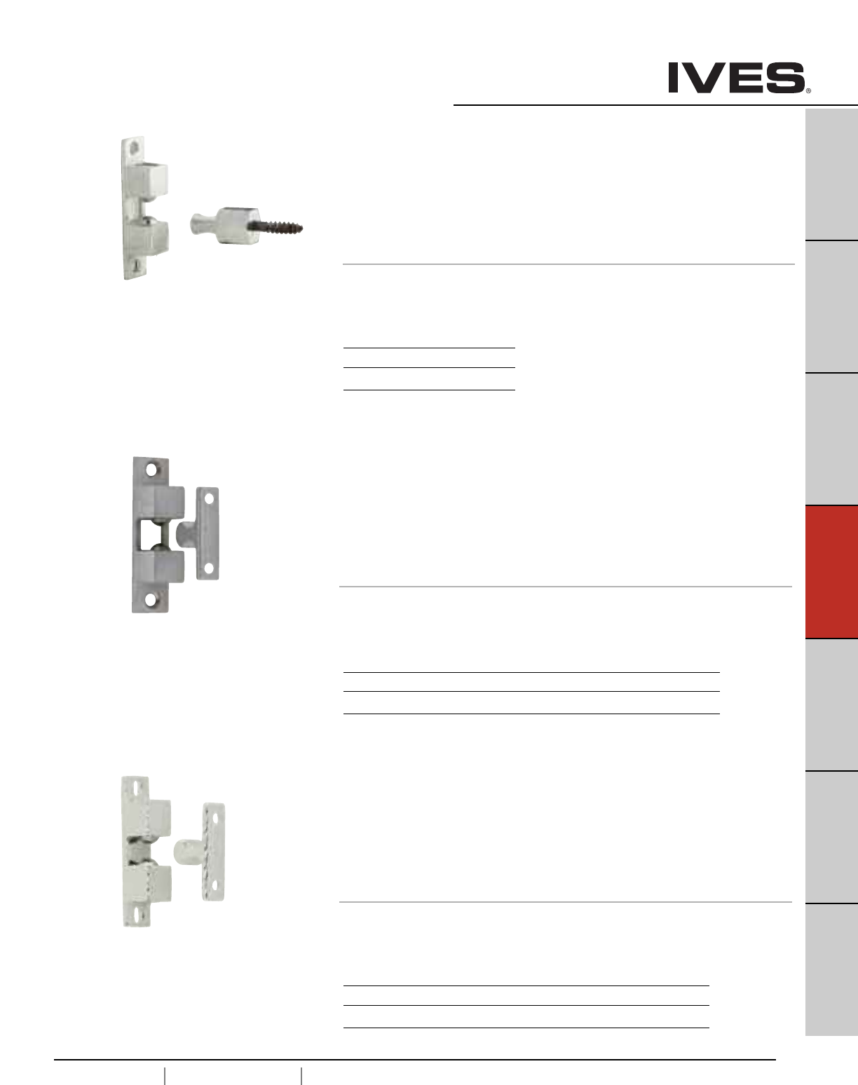
D13
USA 1.877.671.7011 Canada 1.905.403.1800 www.ives.ingersollrand.com
B
Pulls & Plates
A
Hinges & Pivots
C
Flush Bolts & Coordinators
D13
Latches, Catches & Bolts
E
Stops
F
Exterior Hardware
G
Miscellaneous Hardware
Ball Catches
CL21A Ball Catch
• Four-way catch with plate type strike.
• Ideal for closet doors, access doors, hinged openings and numerous
other applications.
• The strike slides between two stainless steel balls that are under
spring tension. As the strike engages, the door is held tightly shut.
• Strike can enter body from any direction.
• Spring tension is easily adjusted to suit field conditions.
• Body can be surface applied or mortised.
• Brass construction.
Dimensions
Body: 3/4" Wide x 3" High x 3/4" Deep
Strike: 7/16" Wide x 1-3/4" High x 7/8" Deep
CL22 Ball Catch
• Three-way catch with plate type strike.
• Ideal for smaller cabinet doors or panels.
• The strike slides between two stainless steel balls that are under
spring tension. As the strike engages, the door is held tightly shut.
• Strike can enter body from either side or front.
• Spring tension is easily adjusted to suit field conditions.
• Body can be surface applied or mortised.
• Brass construction.
Dimensions
Body: 1/2" Wide x 2-3/16" High x 1/2" Deep
Strike: 3/8" Wide x 1-3/8" High x 5/8" Deep
CL21 Ball Catch
• Four-way catch with hexagon stud.
• Ideal for holding medium duty doors.
• The strike slides between two stainless steel balls that are under
spring tension. As the strike engages, the door is held tightly shut.
• Strike can enter body from any direction.
• Spring tension is easily adjusted to suit field conditions.
• Body can be surface applied or mortised.
• Brass construction.
Dimensions
Body: 3/4" Wide x 3" High x 3/4" Deep
Strike: 3/4" Wide Hex x 1-1/2" High
Meets ANSI/BHMA A156.9
Meets ANSI/BHMA A156.9, B13292
Meets ANSI/BHMA 156.9, B13302.
Finishes brass
Ives Number US26D
BHMA 626
Finishes brass
Ives Number US3 US4 US10 US26 US26D
BHMA 605 606 612 625 626
Finishes brass
Ives Number US3 US4 US10 US26 US26D
BHMA 605 606 612 625 626
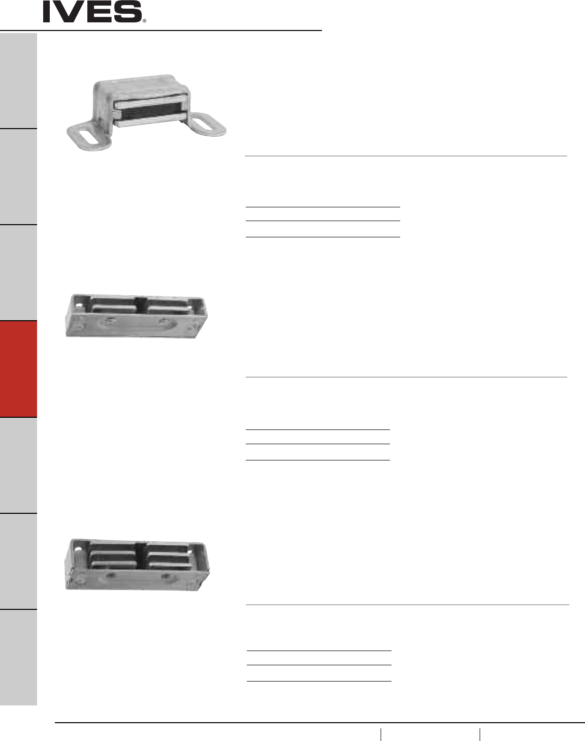
D14
USA 1.877.671.7011 Canada 1.905.403.1800 www.ives.ingersollrand.com
B
Pulls & Plates
A
Hinges & Pivots
C
Flush Bolts & Coordinators
D14
Latches, Catches & Bolts
E
Stops
F
Exterior Hardware
G
Miscellaneous Hardware
Magnetic Catches
325 Magnetic Catch
• Double pole.
• Self aligning magnet insures maximum pull.
• Case design allows easy magnet adjustment on cabinet
or small door applications.
• Aluminum case.
• Packed with sheet metal screws.
• 5 lbs. Load Capacity
Dimensions
Case: 1-1/8" wide x 2-1/16" Long x 5/8" Thick
327 Super-Mite®Heavy Duty Magnetic Catch
• Dual triple pole.
• Self-aligning magnets insure maximum pull.
• Can be surface mounted or mortised.
• Aluminum case.
• Packed with sheet metal screws, 2 short strikes and
1 long strike.
• 14 lbs. Load Capacity
Dimensions
Case: 1" Wide x 3-1/8" Long x 3/4" Thick
326 Mighty-Mite®Heavy Duty Magnetic Catch
• Dual double pole.
• Self-aligning magnets insure maximum pull.
• Can be surface mounted or mortised.
• Aluminum case.
• Packed with sheet metal screws, 2 short strikes and
1 long strike.
• 9 lbs. Load Capacity
Dimensions
Case: 1" Wide x 3-1/8" Long x 9/16" Thick
Finishes aluminum
Ives Number A3 A92
BHMA 666 673
Finishes aluminum
Ives Number A3 A92
BHMA 666 673
Finishes aluminum
Ives Number A3 A92
BHMA 666 673
Meets ANSI/BHMA A156.9 B43171.
Meets ANSI/BHMA A156.9 B43161.
Meets ANSI/BHMA A156.9 B43161.
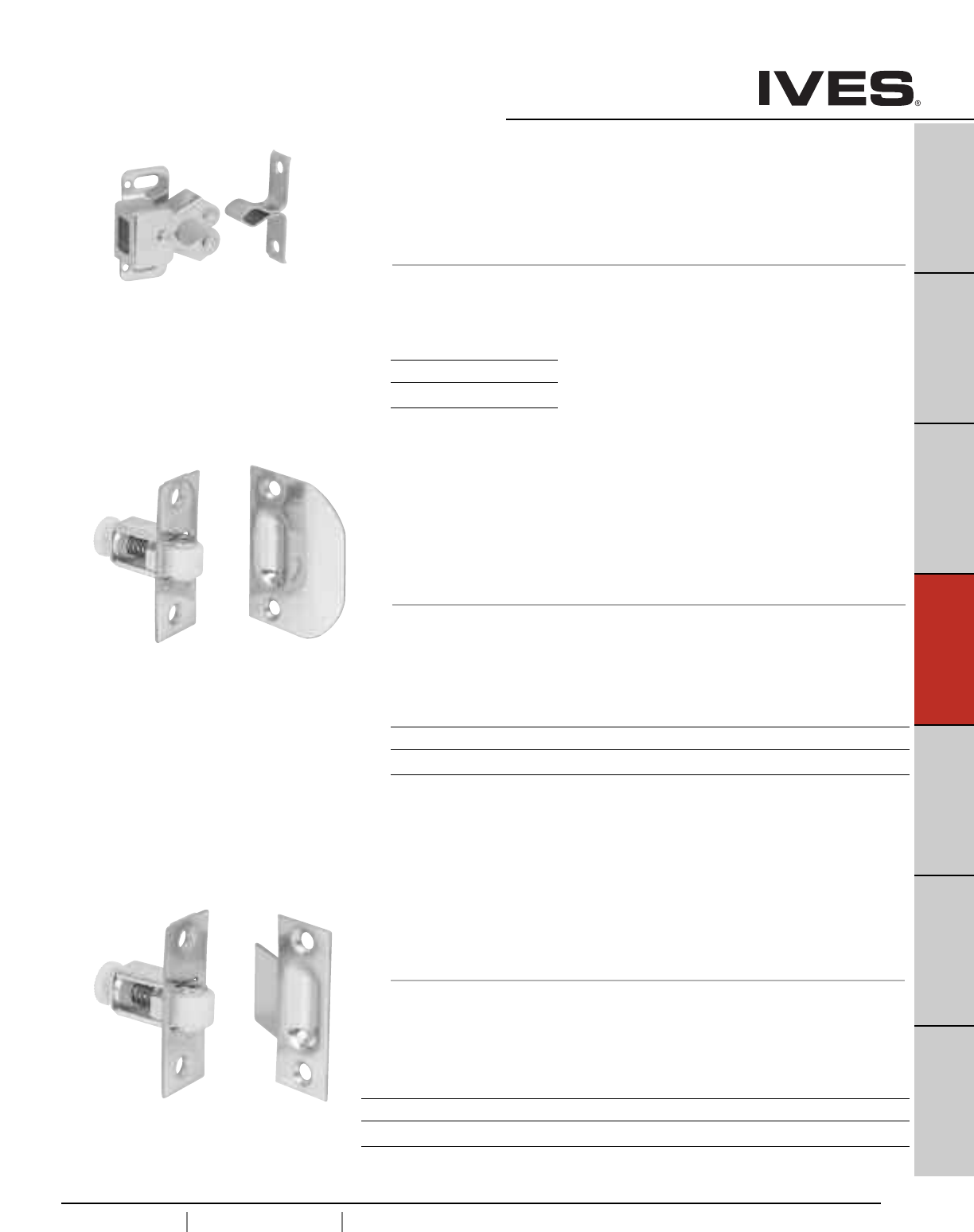
D15
USA 1.877.671.7011 Canada 1.905.403.1800 www.ives.ingersollrand.com
B
Pulls & Plates
A
Hinges & Pivots
C
Flush Bolts & Coordinators
D15
Latches, Catches & Bolts
E
Stops
F
Exterior Hardware
G
Miscellaneous Hardware
Roller Catches
335 Roller Catch
• Smooth, positive latching action insured by powerful conical spring.
• Durable nylon roller insures quiet operation.
• Adjustable tension. Adjustments can be varied from 4 to 17 lbs.
of holding power making possible a wide range of door performance.
• Easily installed on thin doors.
• Full lip style strike designed for simplified mortising.
• Made from wrought brass or wrought steel.
• Packed with sheet metal screws.
Dimensions
Face Plate: 7/8" Wide x 2-1/4" High
Bore: 1-3/4" Deep x 13/16" Diameter
Strike: 1-5/8" Wide x 2-1/4" High, Lip to center- 1-3/16"
336 Roller Catch
• Smooth, positive latching action insured by powerful conical spring.
• Durable nylon roller insures quiet operation.
• Adjustable tension. Adjustments can be varied from 4 to 17 lbs.
of holding power making possible a wide range of door performance.
• Easily installed on thin doors.
• Standard box type strike designed for neat appearance.
• Made from wrought brass or wrought steel.
• Packed with sheet metal screws.
Dimensions
Face Plate: 7/8" Wide x 2-1/4" High
Bore: 13/16" Diameter x 1-3/4" Deep
Strike: 7/8" Wide x 2-1/4" High, Lip to center- 1-1/8"
Meets ANSI/BHMA A156.16 L27081 for brass
and L87081 for steel.
Meets ANSI/BHMA A156.16 L27081 for brass
and L87801 for steel.
Finishes
Ives Number B3 B5 B10 B10B B15 B26 B26D
BHMA 605 609 612 613 619 625 626
330 Roller Catch
• Independent rollers allow positive action and self-alignment.
• Cushioned rollers absorb shock and noise, hold door away from cabinet.
• Application allows for easy adjustment.
• Made from wrought steel.
• Packed with screws and brads.
Dimensions
Case: 1-1/4" High x 11/16" Wide
Strike: 1-1/4" High x 3/8" Wide
Meets ANSI/BHMA A156.9 B83071.
Finishes
Ives Number F2C
BHMA 603
Finishes
Ives Number B3 B4 B5 B10 B10B B15 B26 B26D
BHMA 605 606 609 612 613 619 625 626
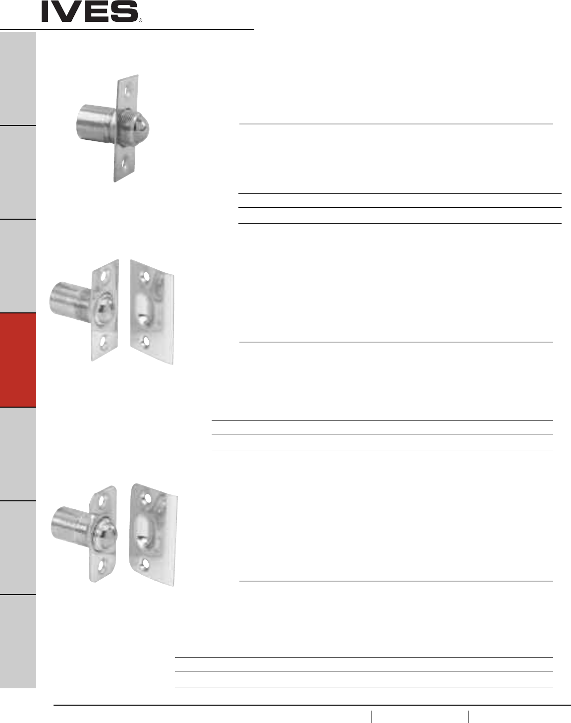
D16
USA 1.877.671.7011 Canada 1.905.403.1800 www.ives.ingersollrand.com
B
Pulls & Plates
A
Hinges & Pivots
C
Flush Bolts & Coordinators
D16
Latches, Catches & Bolts
E
Stops
F
Exterior Hardware
G
Miscellaneous Hardware
Ball Catches
345 Adjustable Ball Catch
• Ideal for cabinets and small interior doors.
• Free rolling ball insures smooth, positive and trouble-free action.
• Adjustable threaded barrel compensates for various door clearances.
• Adjustable spring tension.
• Made from wrought brass.
Dimensions
Face Plate: 3/4" Wide x 1-1/2" High
Bore: 1" Deep x 9/16" Diameter
Strike: 25/32" Wide x 1-1/2" High, Lip to center- 13/32"
347 Dual Adjustable Ball Catch
• For catch in door installations.
• Dual adjustment for door clearance and holding strength.
• Lip strike is designed for use where strike is mounted in jamb.
• Free rolling ball insures smooth, positive and trouble-free action.
• Adjustable threaded barrel compensates for various door clearances.
• Adjustable spring tension.
• Made from wrought brass.
Dimensions
Face Plate: 1" Wide x 2-1/8" High
Bore: 7/8" Diameter x 1-3/8" Deep
Strike: 1-3/8" Wide x 2-1/8" High, Lip to center- 7/8"
349 Ball Catch
• For catch in door installations.
• Radiused corners allow easy installation with a router.
• Dual adjustment for door clearance and holding strength.
• Lip strike is designed for use where strike is mounted in jamb.
• Free rolling ball insures smooth, positive and trouble-free action.
• Adjustable threaded barrel compensates for various door clearances.
• Adjustable spring tension.
• Made from wrought brass.
Dimensions
Face Plate: 1" Wide x 2-1/8" High
Bore: 7/8" Diameter x 1-3/8" Deep
Strike: 1-3/8" Wide x 2-1/8" High, Lip to center- 7/8"
Meets ANSI/BHMA A156.9 B23013.
Meets ANSI/BHMA A156.9 B23013.
Meets ANSI/BHMA A156.9 B23013.
Finishes brass
Ives Number B3 B5 B10 B10B B15 B26 B26D
BHMA 605 609 612 613 619 625 626
Finishes brass
Ives Number B3 B4 B5 B10 B10B B15 B26 B26D
BHMA 605 606 609 612 613 619 625 626
Finishes brass
Ives Number B3 B4 B5 B10 B10B B15 B26 B26D B716
BHMA 605 606 609 612 613 619 625 626
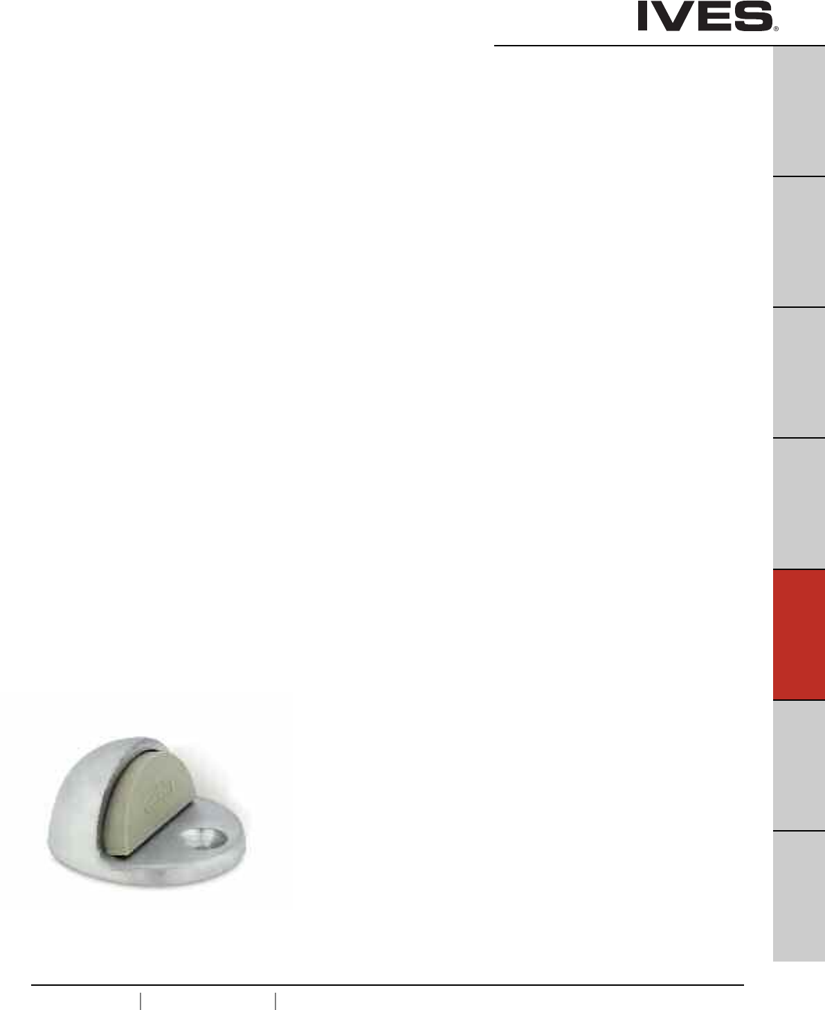
E1
USA 1.877.671.7011 Canada 1.905.403.1800 www.ives.ingersollrand.com
Door Stops
B
Pulls & Plates
A
Hinges & Pivots
C
Flush Bolts & Coordinators
D
Latches, Catches & Bolts
E1
Stops
F
Exterior Hardware
G
Miscellaneous Hardware
Table Of Contents
Floor Stops page
FS13 Floor Stop . . . . . . . . . . . . . . . . . . . . . . . . . . . . . . . . . . . . . . . . . . . .E2
R14 Riser . . . . . . . . . . . . . . . . . . . . . . . . . . . . . . . . . . . . . . . . . . . . . . . . .E2
FS17 Floor Stop . . . . . . . . . . . . . . . . . . . . . . . . . . . . . . . . . . . . . . . . . . . .E2
FS18, FS18L Floor Stop . . . . . . . . . . . . . . . . . . . . . . . . . . . . . . . . . . . . . .E3
FS436 Floor Stop . . . . . . . . . . . . . . . . . . . . . . . . . . . . . . . . . . . . . . . . . . .E4
FS438 Floor Stop . . . . . . . . . . . . . . . . . . . . . . . . . . . . . . . . . . . . . . . . . . .E4
R435 Riser . . . . . . . . . . . . . . . . . . . . . . . . . . . . . . . . . . . . . . . . . . . . . . .E4
R437 Riser . . . . . . . . . . . . . . . . . . . . . . . . . . . . . . . . . . . . . . . . . . . . . . . .E4
430 Floor Stop . . . . . . . . . . . . . . . . . . . . . . . . . . . . . . . . . . . . . . . . . . . . .E4
FS441, FS441WS Floor Stop . . . . . . . . . . . . . . . . . . . . . . . . . . . . . . . . . .E5
FS444, FS448 Floor Stop . . . . . . . . . . . . . . . . . . . . . . . . . . . . . . . . . . . . .E5
Floor Stop & Holder
FS9 Floor Stop & Semi-automatic Holder . . . . . . . . . . . . . . . . . . . . . . . .E6
FS40, FS41, FS42, FS43 Floor Stop & Automatic Holder . . . . . . . . . . . . .E6
FS446, FS450 Floor Stop & Manual Holder . . . . . . . . . . . . . . . . . . . . . . .E7
FS495, FS496, FS497 Floor Stop & Automatic Holder . . . . . . . . . . . . . . .E8
Wall Bumpers/Stops
WS11, WS11X Wall Stop . . . . . . . . . . . . . . . . . . . . . . . . . . . . . . . . . . . . .E9
WS20, WS20X Manual Wall Holder . . . . . . . . . . . . . . . . . . . . . . . . . . . . .E9
WS33, WS33X Wall Stop . . . . . . . . . . . . . . . . . . . . . . . . . . . . . . . . . . . .E10
WS65 Wall Stop . . . . . . . . . . . . . . . . . . . . . . . . . . . . . . . . . . . . . . . . . . .E10
WS401, WS402 Wall Bumper . . . . . . . . . . . . . . . . . . . . . . . . . . . . . . . . .E11
WS404 Wall Bumper . . . . . . . . . . . . . . . . . . . . . . . . . . . . . . . . . . . . . . . .E11
WS406, WS407 Wall Bumper . . . . . . . . . . . . . . . . . . . . . . . . . . . . . . . . .E12
411R Wall Bumper . . . . . . . . . . . . . . . . . . . . . . . . . . . . . . . . . . . . . . . . .E13
WS443, WS447 Wall Stop . . . . . . . . . . . . . . . . . . . . . . . . . . . . . . . . . . . .E14
WS445, WS449 Manual Wall Holder . . . . . . . . . . . . . . . . . . . . . . . . . . .E14
Wall Holders
WS40 Automatic Wall Holder . . . . . . . . . . . . . . . . . . . . . . . . . . . . . . . . .E15
WS45, WS45X Automatic Wall Holder . . . . . . . . . . . . . . . . . . . . . . . . . .E15
Kick Down Holder
FS452 Kick Down Holder . . . . . . . . . . . . . . . . . . . . . . . . . . . . . . . . . . . .E16
FS455 Kick Down Holder . . . . . . . . . . . . . . . . . . . . . . . . . . . . . . . . . . . .E16
FS544, FS555 Kick Down Holder . . . . . . . . . . . . . . . . . . . . . . . . . . . . . .E17
Plunger Door Holders
FS1153 . . . . . . . . . . . . . . . . . . . . . . . . . . . . . . . . . . . . . . . . . . . . . . . . . .E18
FS1154 . . . . . . . . . . . . . . . . . . . . . . . . . . . . . . . . . . . . . . . . . . . . . . . . . .E18
Roller Bumpers
RB470, RB471, RB472 Roller Bumper . . . . . . . . . . . . . . . . . . . . . . . . . .E19
Residential Door stops
060, 061 Flexible Door Stop . . . . . . . . . . . . . . . . . . . . . . . . . . . . . . . . .E20
60, 61 Door Base Stop . . . . . . . . . . . . . . . . . . . . . . . . . . . . . . . . . . . . . .E20
63 Flexible Door Stop . . . . . . . . . . . . . . . . . . . . . . . . . . . . . . . . . . . . . .E21
64 Door Base Stop . . . . . . . . . . . . . . . . . . . . . . . . . . . . . . . . . . . . . . . . .E21
Hinge Pin Stops
69 . . . . . . . . . . . . . . . . . . . . . . . . . . . . . . . . . . . . . . . . . . . . . . . . . . . . . .E21
70 . . . . . . . . . . . . . . . . . . . . . . . . . . . . . . . . . . . . . . . . . . . . . . . . . . . . . .E22
72Z Residential Door Saver . . . . . . . . . . . . . . . . . . . . . . . . . . . . . . . . . .E22
73Z Commercial Door Saver . . . . . . . . . . . . . . . . . . . . . . . . . . . . . . . . . .E22
Silencers
SR64, SR65, SR66 Door Silencer . . . . . . . . . . . . . . . . . . . . . . . . . . . . . .E23
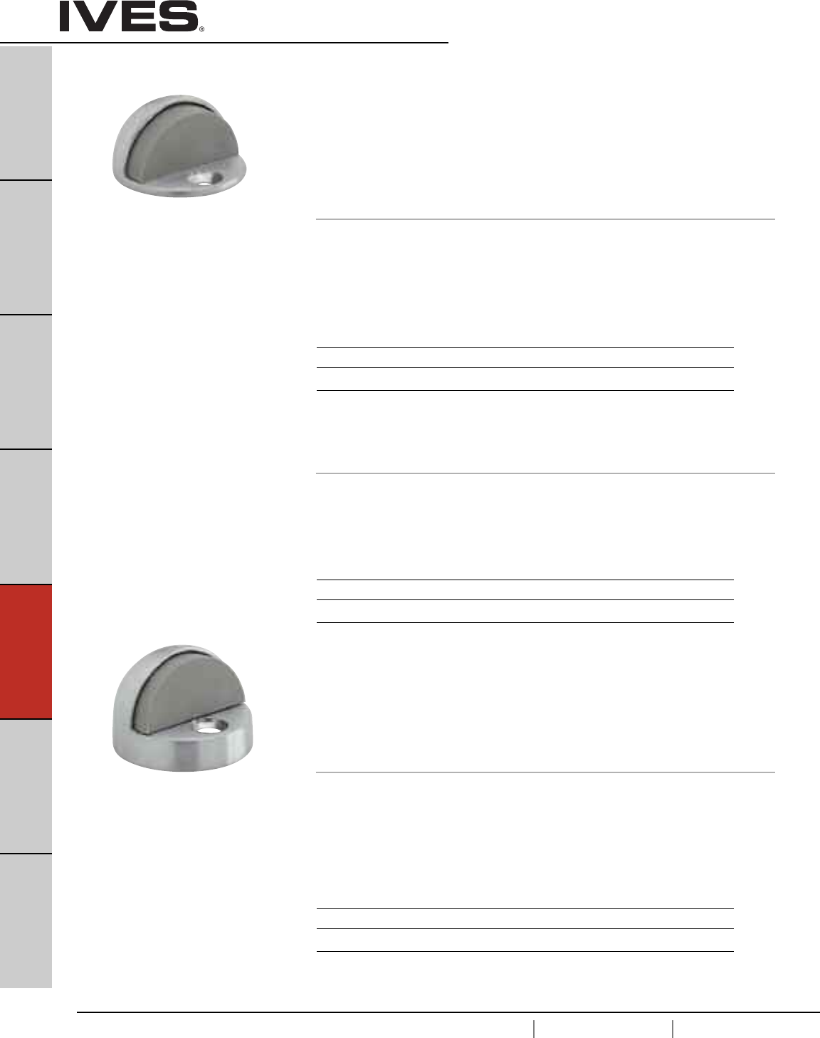
E2
USA 1.877.671.7011 Canada 1.905.403.1800 www.ives.ingersollrand.com
Floor Stops —Dome
B
Pulls & Plates
A
Hinges & Pivots
C
Flush Bolts & Coordinators
D
Latches, Catches & Bolts
E2
Stops
F
Exterior Hardware
G
Miscellaneous Hardware
FS13 Dome Stop
• Standard FS13 for use where no threshold is used.
• Heavy-Duty Cast Dome Stops constructed of brass.
•Unique riser design of R14 (below) allows easy conversion to
threshold application.
• Units are packed with fasteners sufficient for mounting in all types of
floor construction, including concrete.
• Replaceable grey rubber bumper.
Dimensions
Overall Height: 1"
Base Height: 5/32"
Base Diameter: 1-3/4"
Finishes
Ives Number US3 US4 US10 US10B US26 US26D
BHMA 605 606 612 613 625 626
FS17 Dome Stop
• One piece dome stop for use with thresholds.
• Heavy-Duty Cast Dome Stops constructed of brass.
• Units are packed with fasteners sufficient for mounting in all types of
floor construction, including concrete.
• Replaceable grey rubber bumper.
Dimensions
Overall Height: 1-11/32"
Base Height: 1/2"
Base Diameter: 1-3/4" round
Finishes
Ives Number US3 US4 US10 US10B US26 US26D
BHMA 605 606 612 613 625 626
Meets ANSI/BHMA 156.6, L12141.
Meets ANSI/BHMA 156.6, L12161.
R14 Dome Stop Rise
• Adapts the FS13 Dome Stop to threshold use.
• Brass Die Cast Construction.
Dimensions
Riser Height: 5/16"
Base Diameter: 1-3/4" round
Finishes
Ives Number US3 US4 US10 US10B US26 US26D
BHMA 605 606 612 613 625 626
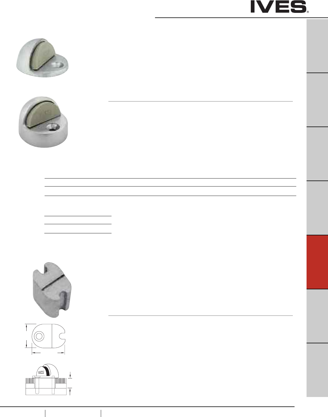
E3
USA 1.877.671.7011 Canada 1.905.403.1800 www.ives.ingersollrand.com
Floor Stops —Dome
B
Pulls & Plates
A
Hinges & Pivots
C
Flush Bolts & Coordinators
D
Latches, Catches & Bolts
E3
Stops
F
Exterior Hardware
G
Miscellaneous Hardware
FS436 Dome Stop
FS438 Dome Stop
• FS436 for doors without threshold.
• FS438 for doors with threshold or undercut doors.
• Heavy-Duty Cast Dome Stops constructed of brass, bronze or aluminum.
• Packed with wood screw and plastic anchor.
Replaceable gray, non-marring rubber bumper.
Dimensions
FS436
Overall Height: 1"
Base Height: 3/16"
Base Diameter: 1-3/4" x 2" Oval
PA D
FLOOR
1" OR
LESS
1"
1-7/16"
R435 Riser for FS436 Dome Stop
R437 Riser for FS438 Dome Stop
• Extruded aluminum, mill finish.
• R435 for conversion of FS436 Dome Stop to carpet installation.
• R437 For conversion of FS438 Dome Stop to carpet installation.
• Packed with wood screws, lead shield and stud.
Specify Tampin (TPN) if required.
Dimensions
Available in 1/4", 3/8", 1/2", 5/8", 3/4" and 1" height.
FS438
Meets ANSI/BHMA 156.16, L12141 for brass
or bronze and L32141 for aluminum.
Finishes brass
Ives Number US3 US4 US5 US10 US10B US15 US620* US26 US26D B716
BHMA 605 606 609 612 613 619 620 625 626
* only available for FS436 in slim pack of 15 per box.
Finishes aluminum
Ives Number US28
BHMA 628
FS436
Meets ANSI/BHMA 156.16, L12141 for brass
or bronze and L32141 for aluminum.
FS438
Overall Height: 1-3/8"
Base Height: 9/16"
Base Diameter: 1-3/4" x 2" Oval
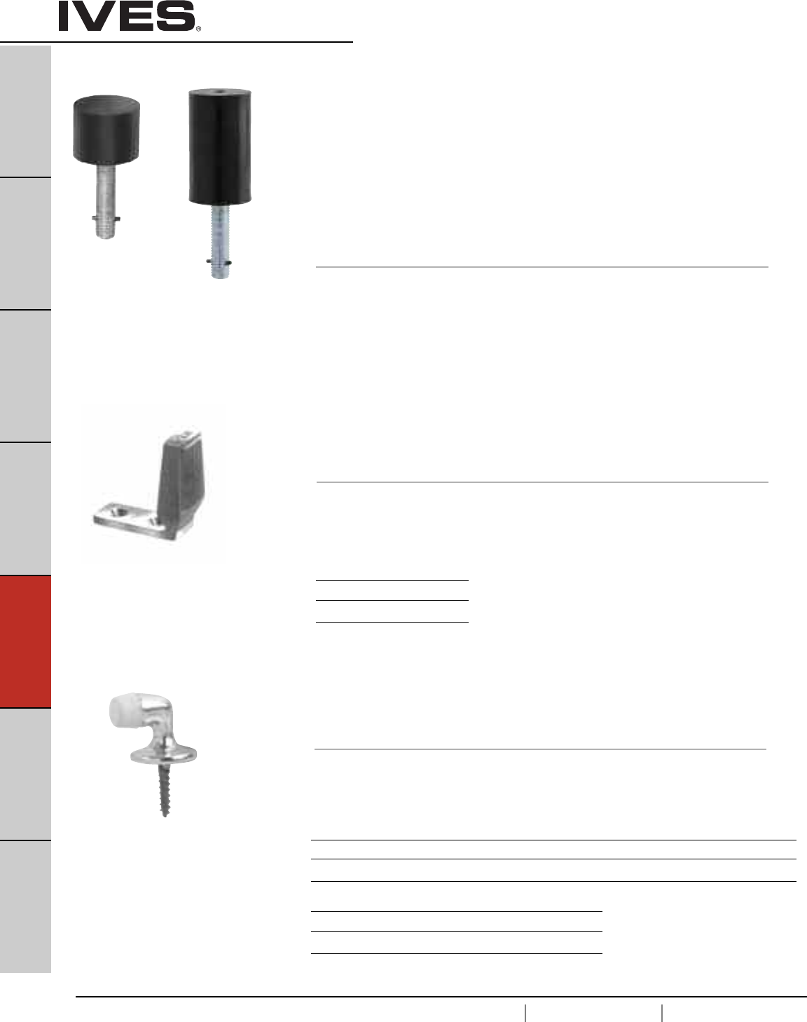
E4
USA 1.877.671.7011 Canada 1.905.403.1800 www.ives.ingersollrand.com
Floor Stops
B
Pulls & Plates
A
Hinges & Pivots
C
Flush Bolts & Coordinators
D
Latches, Catches & Bolts
E4
Stops
F
Exterior Hardware
G
Miscellaneous Hardware
FS18S
FS18L Floor Stops
• Security Door Stops designed for use in high vandalism areas.
• Molded from black flame resistant, resilient material around a
heavy-duty stud.
• Once grouted in concrete, leaves no exposed fasteners to be
tampered with or removed.
• Ideal for jail or security cell areas where floor mounted stops are required.
• FS18L also ideal for concrete wall applications.
Dimensions
FS18S Height: 1-1/2" FS18L Height: 3-1/2"
FS18S Diameter: 2" FS18L Diameter: 2"
FS18S Stud Length: 2-1/2" FS18L Stud Length: 2-1/2"
FS18LFS18S
FS434 Floor Stop
• Burnished wrought steel.
• For undercut doors up to 1-1/2".
• Packed with screws and plastic anchors.
• Replaceable soft, resilient gray rubber.
Dimensions
Overall Height: 2-5/8"
Base Size: 1-1/2" W x 2-3/4" L
Finishes
Ives Number USC
BHMA 604
430 Floor Door Stop
• Burnished wrought steel.
• For undercut doors up to 1-1/2".
• Packed with screws and plastic anchors.
• Replaceable soft, resilient gray rubber.
Dimensions
Overall Height: 1-5/16"
Base Diameter: 1-1/4"
Finishes brass
Ives Number B3 B4 B5 B10B B15 B26 B26D
BHMA 605 606 609 613 619 625 626
Finishes aluminum
Ives Number A3* A5 A14 A92
BHMA 666 669 673
* only available in Slim-Pak of 25
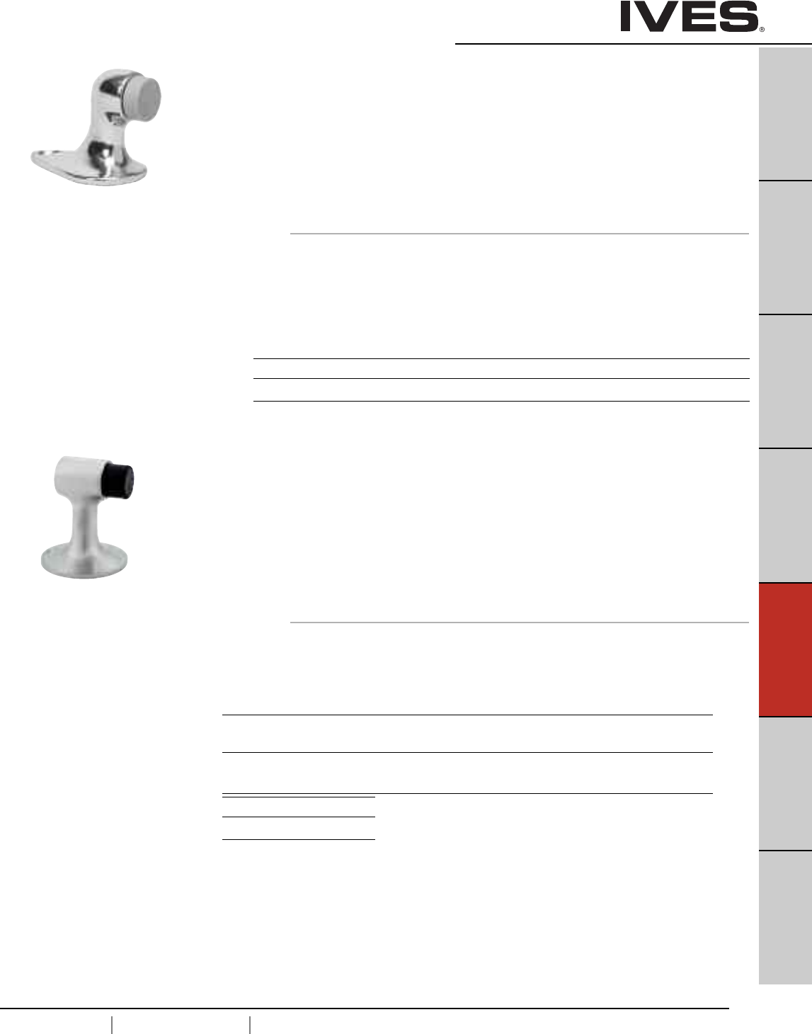
E5
USA 1.877.671.7011 Canada 1.905.403.1800 www.ives.ingersollrand.com
Floor Stops
B
Pulls & Plates
A
Hinges & Pivots
C
Flush Bolts & Coordinators
D
Latches, Catches & Bolts
E5
Stops
F
Exterior Hardware
G
Miscellaneous Hardware
FS441 Floor Stop
• Accommodates door undercut up to 1-1/2".
• Designed to blend well with all types of construction and
provide a minimum of hindrance to cleaning efforts.
• Heavy-Duty cast brass or aluminum construction.
• Replaceable Non-marring rubber bumper.
FS441 packed with expansion shield and tampin for masonry type mounting,
and wood screws for drywall mounting.
Dimensions
Overall Height: 2-1/8"
Overall Length: 2-7/8"
Base Depth: 1-5/8"
FS444 Floor Stop
FS448 Floor Stop
• Ideal for interior or exterior use.
• Cast brass construction.
• Accommodates door undercut up to 2-1/2".
• Replaceable Non-marring rubber tip.
FS444 is packed with expansion shield and lead shield, for masonry type mounting.
FS448 is packed with wood screws, for drywall mounting.
Dimensions
Overall Height: 3"
Base Diameter: 2-1/2"
Finishes brass
Ives Number US3 US4 US5 US10 US10B US15 US26 US26D
BHMA 605 606 609 612 613 619 625 626
Finishes brass
Ives Number US3 US4 US5* US10 US10B US15 US26 US26D
BHMA 605 606 609 612 613 619 625 626
Finishes aluminum
Ives Number US28*
BHMA 628
FS444
Meets ANSI/BHMA 156.16, L12131 for brass
FS448
Meets ANSI/BHMA 156.16,
L12121 for brass and L32121 for aluminum
Meets ANSI/BHMA 156.16, L12131 for brass
* not available on FS444
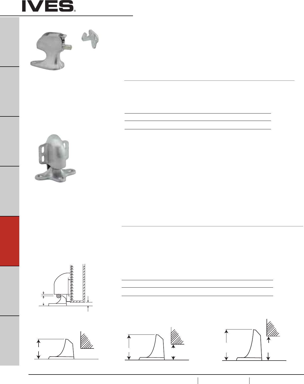
E6
USA 1.877.671.7011 Canada 1.905.403.1800 www.ives.ingersollrand.com
Floor Stops
B
Pulls & Plates
A
Hinges & Pivots
C
Flush Bolts & Coordinators
D
Latches, Catches & Bolts
E6
Stops
F
Exterior Hardware
G
Miscellaneous Hardware
FS40 Floor Stop & Automatic Holder
FS41
FS42
FS43
• Automatic door holders ideal for heavy-traffic situations that require
a simple, fool-proof, Hold-Open device.
• Forged from brass.
• Unit is activated automatically when door is opened.
A firm pull on door releases the mechanism.
• Strikes accommodate different door to floor clearances.
• Model numbers are determined by strike/door-to-floor clearances.
• Holder position on door is adjustable.
• Universal screw pack allows for installation in all types of door construction.
Dimensions
Door to Floor Clearance: FS40 1/2" or less
FS41 9/16" to 1-1/16"
FS42 1-1/8" to 1-9/16"
FS43 1-5/8" to 2-1/16"
Holder Dimensions: 3" Wide x 3-11/16" High
1-3/16”
SIDE VIEW BODY
F40 MAX. DOOR
CLEARANCE
1/2”
1/8” CLEARANCE
1-3/4” CLEARANCE
FROM 9/16 to 1-1/16
2-1/4” CLEARANCE
FROM 1-1/8 to 1-9/16
2-3/4”
CLEARANCE
FROM 1-5/8 to 2-1/16
FS41 FS42 FS43
Meets ANSI/BHMA 156.16, L11301
Finishes brass
Ives Number US3 US4 US10 US10B US26 US26D
BHMA 605 606 612 613 625 626
FS9 Floor Stop & Semi-Automatic Holder
• Semi-automatic floor-mounted holders accommodates with door to
floor clearance of 1-1/2" or less.
• Cast from heavy-duty brass.
•Activate holder by flipping the engagement tongue forward. When
door is opened, the hook (mounted on door) engages the tongue.
To release, push firmly on door to disengage tongue.
• Universal screw pack accommodates all types of floor and
door construction.
Dimensions
Overall Height: 3-1/2
Base Dimensions: 2" wide x 3-1/2" long
Finishes
Ives Number US3 US4 US10 US10B US26 US26D
BHMA 605 606 612 613 625 626
Meets ANSI/BHMA 156.16, L11241.
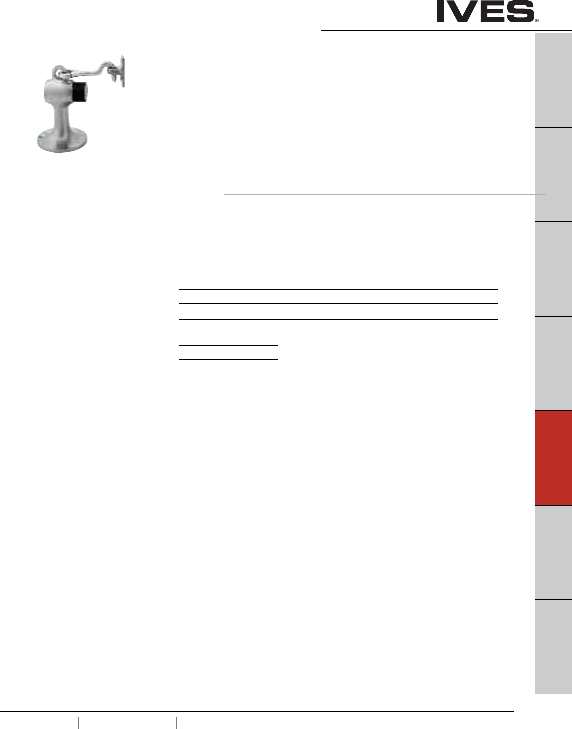
E7
USA 1.877.671.7011 Canada 1.905.403.1800 www.ives.ingersollrand.com
Floor Stops
B
Pulls & Plates
A
Hinges & Pivots
C
Flush Bolts & Coordinators
D
Latches, Catches & Bolts
E7
Stops
F
Exterior Hardware
G
Miscellaneous Hardware
FS446 Floor Stop & Manual Door Holder
FS450 Floor Stop & Manual Door Holder
•Manual type floor holder ideal for interior or exterior use.
• Cast brass or aluminum construction.
• Accommodates door undercut up to 2-1/2".
• Replaceable non-marring rubber tip.
• Unit functions as a stop but serves as a Hold-Open device when
hook is manually engaged in strike. Unit requires manual
disengagement to release Hold-Open.
FS446 packed with expansion shield and lead shield, for masonry type mounting
FS450 packed with 3 wood screws, for drywall mounting.
Dimensions
Overall Height: 3-3/4
Height from Floor to Stop Center Line: 2-5/8"
Stop Diameter: 1-1/16"
Base Diameter: 2-1/12"
Finishes brass
Ives Number US3 US4 US10 US10B US15 US26 US26D
BHMA 605 606 612 613 619 625 626
Finishes aluminum
Ives Number US28
BHMA 628
FS446
Meets ANSI/BHMA 156.16, L11371 for brass
and L31371 for aluminum.
FS450
Meets ANSI/BHMA 156.16, L11361 for brass
and L31371 for aluminum.
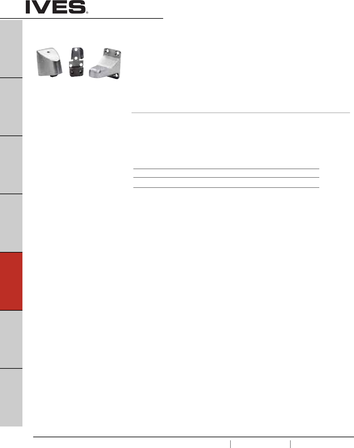
E8
USA 1.877.671.7011 Canada 1.905.403.1800 www.ives.ingersollrand.com
Floor Stops
B
Pulls & Plates
A
Hinges & Pivots
C
Flush Bolts & Coordinators
D
Latches, Catches & Bolts
E8
Stops
F
Exterior Hardware
G
Miscellaneous Hardware
FS495 Wall Stop & Automatic Holder
FS496 Floor Stop & Automatic Holder
FS497 Floor Stop & Automatic Holder
• Automatic door holders ideal for heavy-traffic situations that require a simple,
Hold-Open device.
• Cast brass construction.
• Recommended installation is holder on door and strike on wall.
• Holder position on door is adjustable.
• Holder is tapered to prevent “child riding.”
Dimensions
FS495 Holds door 3-3/4" from wall.
FS496 Door to Floor Clearances 3/8" Maximum.
FS497 Door to Floor Clearances 1" Maximum.
FS495 Meets ANSI/BHMA 156.16, L11291 for brass
FS496 Meets ANSI/BHMA 156.16, L11301 for brass
FS497 Meets ANSI/BHMA 156.16, L11301 for brass
Finishes brass
Ives Number US3 US4* US10 US10B US26 US26D
BHMA 605 606 612 613 625 626
* not available on FS496, FS497.
FS495 shown
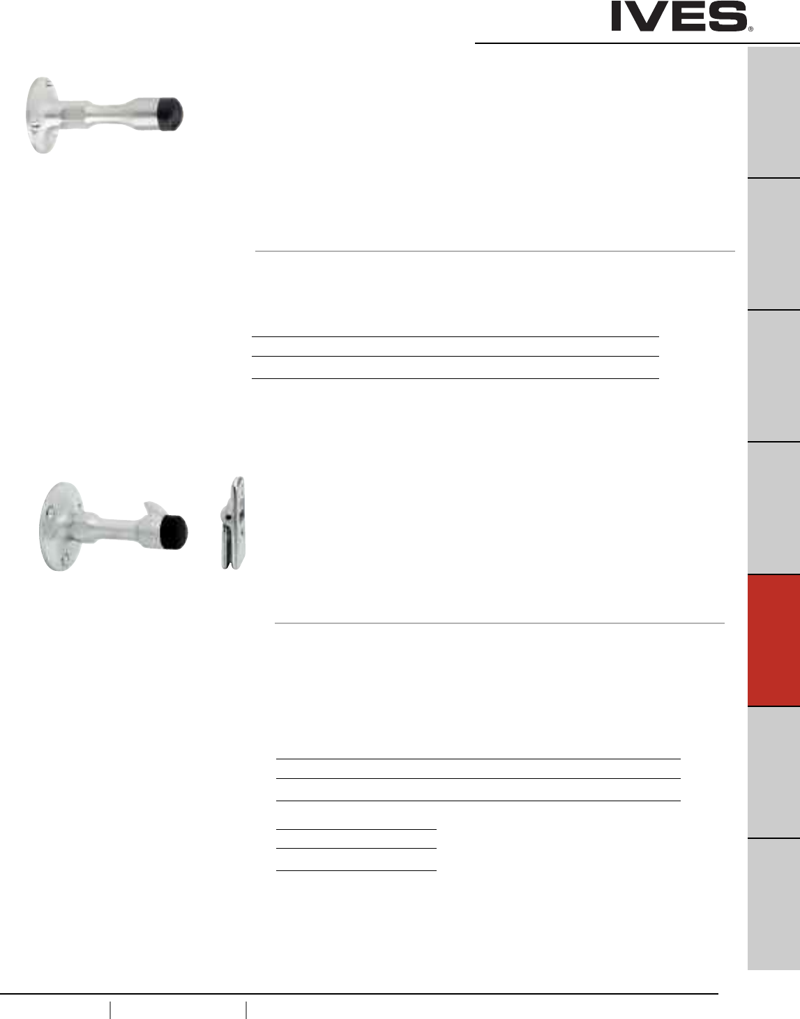
E9
USA 1.877.671.7011 Canada 1.905.403.1800 www.ives.ingersollrand.com
Wall Stops
B
Pulls & Plates
A
Hinges & Pivots
C
Flush Bolts & Coordinators
D
Latches, Catches & Bolts
E9
Stops
F
Exterior Hardware
G
Miscellaneous Hardware
WS11
WS11X Wall Stops
• Constructed in heavy duty cast brass.
• Hexagon section on unit aids in fastening unit when expansion shield is used.
• Replaceable rubber bumpers features off-set shoulder and threaded shank
that screws into body of unit.
WS11 is furnished with wood screws for drywall mounting.
WS11X is furnished with a threaded stud and expansion shield for
masonry type mounting.
Dimensions
Base Diameter: 2"
Overall Projection: 3-3/4"
Finishes brass
Ives Number US3 US4 US10 US10B US26 US26D
BHMA 605 606 612 613 625 626
WS20
WS20X Manual Wall Holders
• Constructed in cast brass or aluminum.
• Replaceable rubber bumpers feature off-set shoulder and threaded shank
that screws into body of holder.
• Hinged strike furnished matches body material and finish.
WS20 is furnished wood screws for drywall mounting.
WS20X is furnished with threaded stud and exspansion shield
for masonry type mounting.
Dimensions
Base Diameter: 2-3/8"
Overall Projection: 4"
Strike Height: 2"
Strike Width: 1"
WS20
Meets ANSI/BHMA 156.16, L11341for brass
and L32341 for aluminum
WS20X
Meets ANSI/BHMA 156.16, L11351 for brass
and L31351 for aluminum
Finishes brass
Ives Number US3 US4 US10 US10B US26 US26D
BHMA 605 606 612 613 625 626
Finishes aluminum
Ives Number US28
BHMA 628
WS11
Meets ANSI/BHMA 156.16, L12011
WS11X
Meets ANSI/BHMA 156.16, L12021
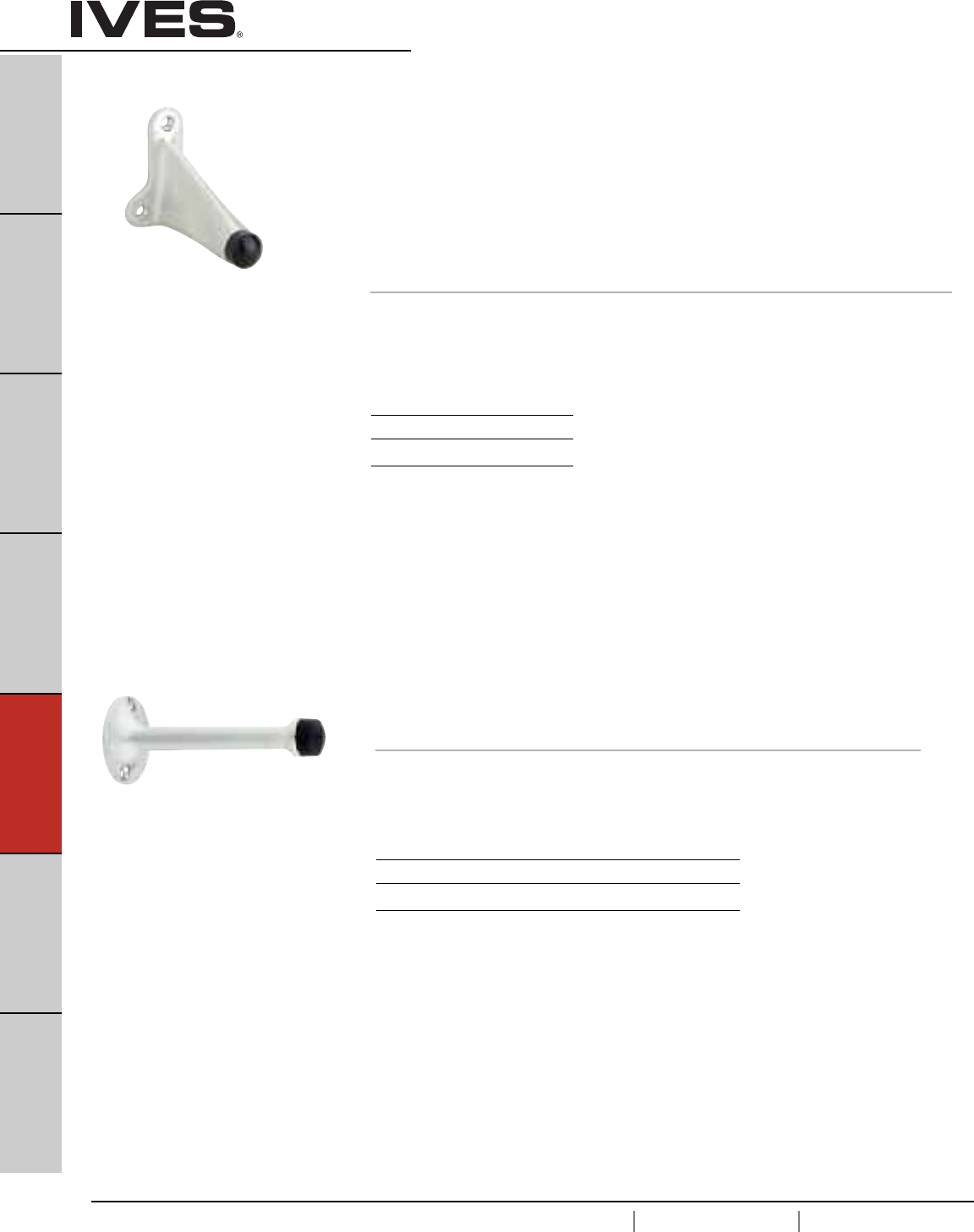
E10
USA 1.877.671.7011 Canada 1.905.403.1800 www.ives.ingersollrand.com
Wall Stops
B
Pulls & Plates
A
Hinges & Pivots
C
Flush Bolts & Coordinators
D
Latches, Catches & Bolts
E10
Stops
F
Exterior Hardware
G
Miscellaneous Hardware
WS33
WS33X Wall Stops
• Constructed in a durable cast brass.
• Replaceable rubber bumper with offset shoulder screws into cavity on body
to prevent loss or theft.
• Sloping design discourages vandalism
WS33 is furnished with wood screws for drywall mounting.
WS33X is furnished with a threaded stud and expansion shield for
masonry type mounting.
Dimensions
Base Diameter: 2-1/4" wide x 3" High
Overall Projection: 3-3/4"
Finishes brass
US Number US26D
BHMA 626
WS33
Meets ANSI/BHMA 156.16, L12011
WS33X
Meets ANSI/BHMA 156.16, L12021
WS65 Wall Stop
• Burnished cast aluminum.
• Replaceable non-marring white rubber bumper.
• Packed with sheet metal screws.
Dimensions
Base Diameter: 1-5/8"
Overall Projection: 3-3/4"
Finishes aluminum
Ives Number US3 US10 US10B US27
BHMA 666 668 703 673
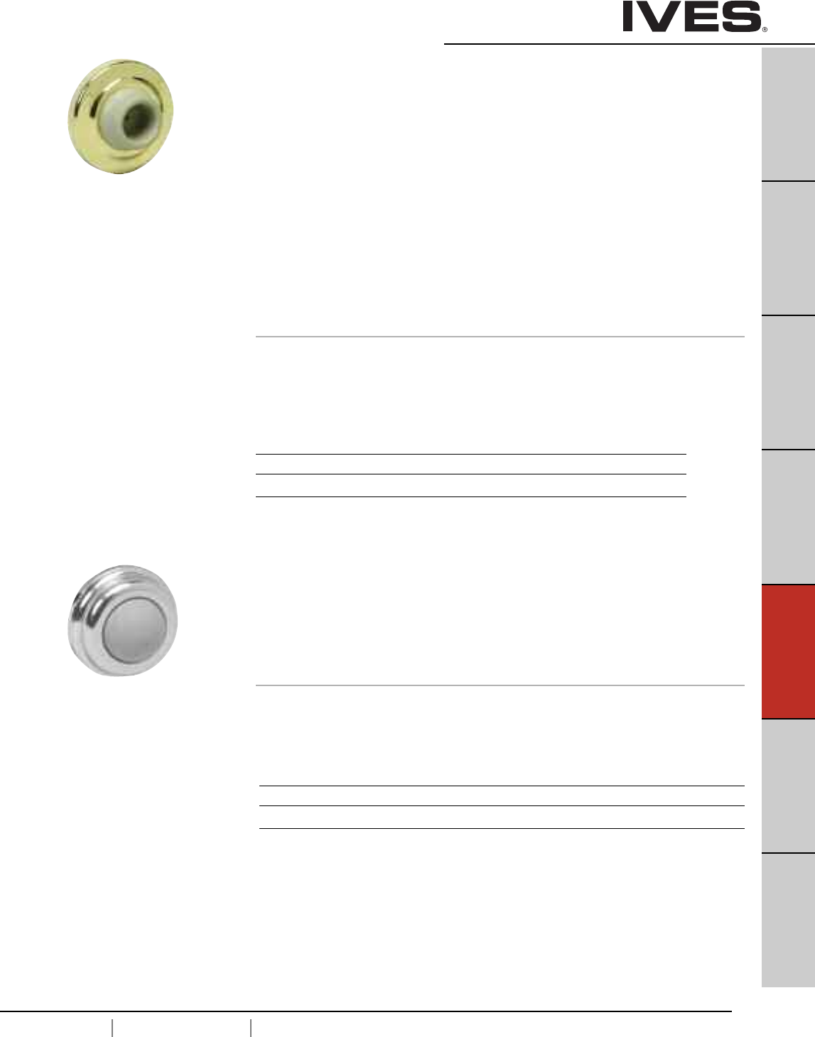
E11
USA 1.877.671.7011 Canada 1.905.403.1800 www.ives.ingersollrand.com
Wall Bumpers
B
Pulls & Plates
A
Hinges & Pivots
C
Flush Bolts & Coordinators
D
Latches, Catches & Bolts
E11
Stops
F
Exterior Hardware
G
Miscellaneous Hardware
WS401CVX Wall Bumpers
WS401CCV
WS402CVX
WS402CCV
• Constructed in heavy-duty cast brass.
• Special retainer cup makes rubber tamper resistant.
WS401CVX (401) – convex rubber bumper, packed with wood screw
and plastic anchor.
WS401CCV (401-1/2) – concave rubber bumper which avoids damage to locks
with projecting buttons, packed with wood screw and plastic anchor.
WS402CVX (402) – convex rubber bumper packed with screw and drywall anchor.
WS402CCV (402-1/2) – concave rubber bumper which avoids damage to locks
with projecting buttons and is packed with screw and drywall anchor.
Dimensions
Base Diameter: 2-1/2"
Base Thickness: 3/8"
Overall Projection: 1"
WS404CVX Wall Bumpers
• Compact size.
• Constructed in cast brass.
• Totally concealed mounting discourages vandalism or tampering.
• Unit furnished with grey convex rubber bumper.
• Packed with sheet metal screw, rawl plug and brad.
Dimensions
Base Diameter: 1"
Overall Projection: 17/32"
WS401CCV & WS402CCV
Meets ANSI/BHMA 156.16 L12251 for brass
WS401CVX & WS402CVX
Meets ANSI/BHMA 156.16 L12101 for brass
Finishes
Ives Number US3 US4 US10 US10B US15 US26 US26D
BHMA 605 606 612 613 619 625 626
Finishes
Ives Number US3 US4 US5 US10 US10B US15 US26 US26D
BHMA 605 606 609 612 613 619 625 626
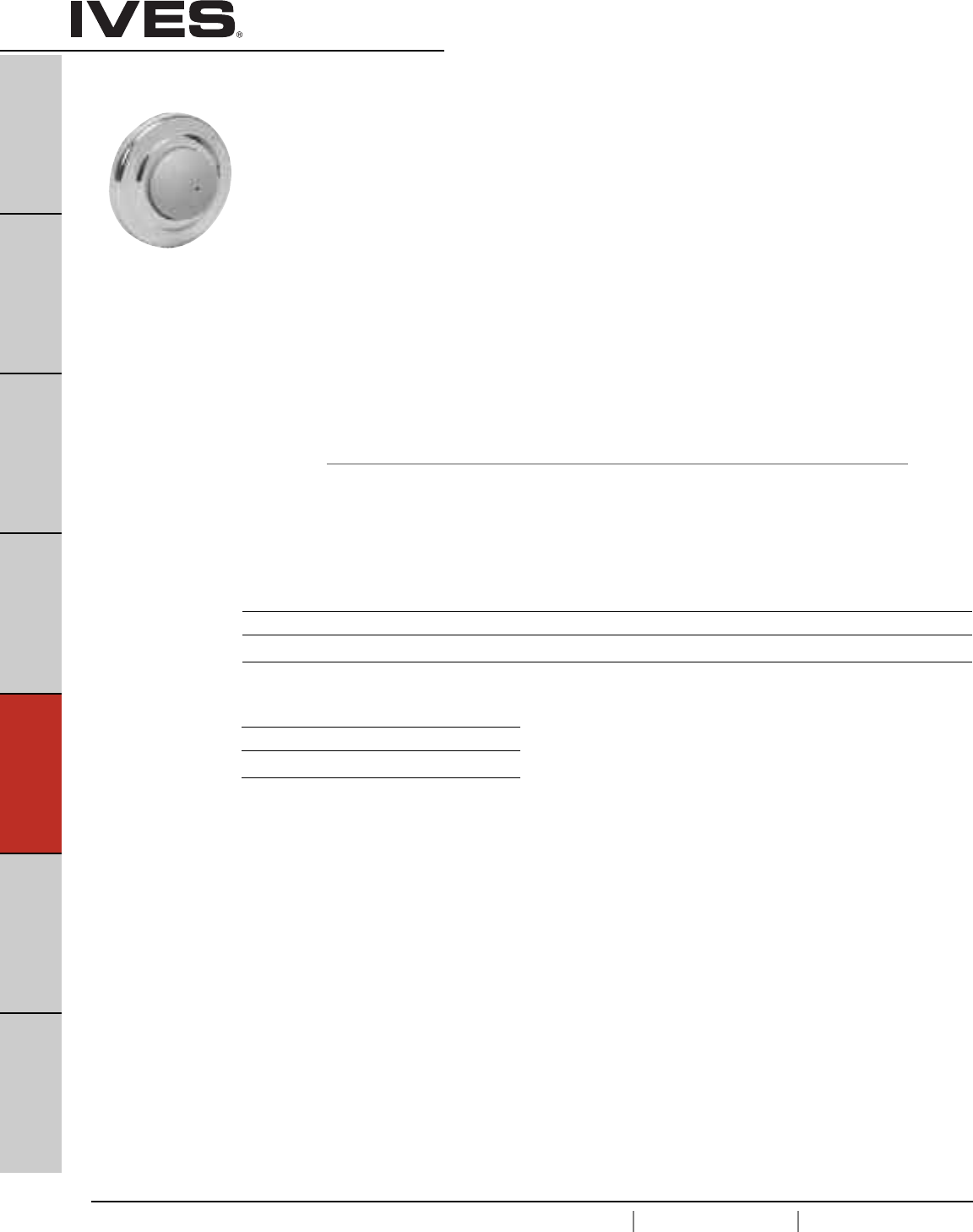
E12
USA 1.877.671.7011 Canada 1.905.403.1800 www.ives.ingersollrand.com
Wall Bumpers
B
Pulls & Plates
A
Hinges & Pivots
C
Flush Bolts & Coordinators
D
Latches, Catches & Bolts
E12
Stops
F
Exterior Hardware
G
Miscellaneous Hardware
WS406CVX & WS407CVX
Meets ANSI/BHMA 156.16 L22201 for brass,
and L52101 for stainless steel.
WS406CCV & WS407CCV
Meets ANSI/BHMA 156.16 L22251 for brass
and and L52251 for stainless steel.
WS406CVX Wall Bumpers
WS406CCV
WS407CVX
WS407CCV
• Constructed in sturdy yet economical wrought base of brass
or stainless steel construction.
• Feature concealed tamper-proof mounting.
• Shipped factory preassembled backplate to reduce installation cost.
• Easy installation by inserting screwdriver through small hole in rubber.
WS406CVX (406) – convex rubber bumper, packed with wood screw
and plastic anchor.
WS406CCV (406-1/2) – concave rubber bumper, which avoids damage to locks with
projecting buttons, packed with wood screw and plastic anchor.
WS407CVX (407) – convex rubber bumper packed with screw and drywall anchor.
WS407CCV (407-1/2) – concave rubber bumper which avoids damage to locks with
projecting buttons and is packed with screw and drywall anchor.
Dimensions
Base Diameter: 2-1/2"
Base Thickness: 3/8"
Overall Projection: 1"
Finishes brass
Ives Number US3 US4 US5* US10 US10B US15 US15A** US26 US26D B716**
BHMA 605 606 609* 612 613 619 620 625 626
Finishes stainless steel
Ives Number US32D
BHMA 630
* only available on WS407CVX Slim-Pak of 15
** available on WS407CCV or WS407CVX Slim-Pak of 15
E13
USA 1.877.671.7011 Canada 1.905.403.1800 www.ives.ingersollrand.com
Wall Bumpers
B
Pulls & Plates
A
Hinges & Pivots
C
Flush Bolts & Coordinators
D
Latches, Catches & Bolts
E13
Stops
F
Exterior Hardware
G
Miscellaneous Hardware
411R-W Wall Bumper
• Adhesive-backed wall door stop for use on clean, smooth, flat surfaces only.
• Non-marring white rubber.
• Concave design permits knob to strike stop without damaging or
engaging lock mechanism.
Dimensions
Base Diameter: 1-7/8"
Base Thickness: 3/8"
Overall Projection: 1-1/16"
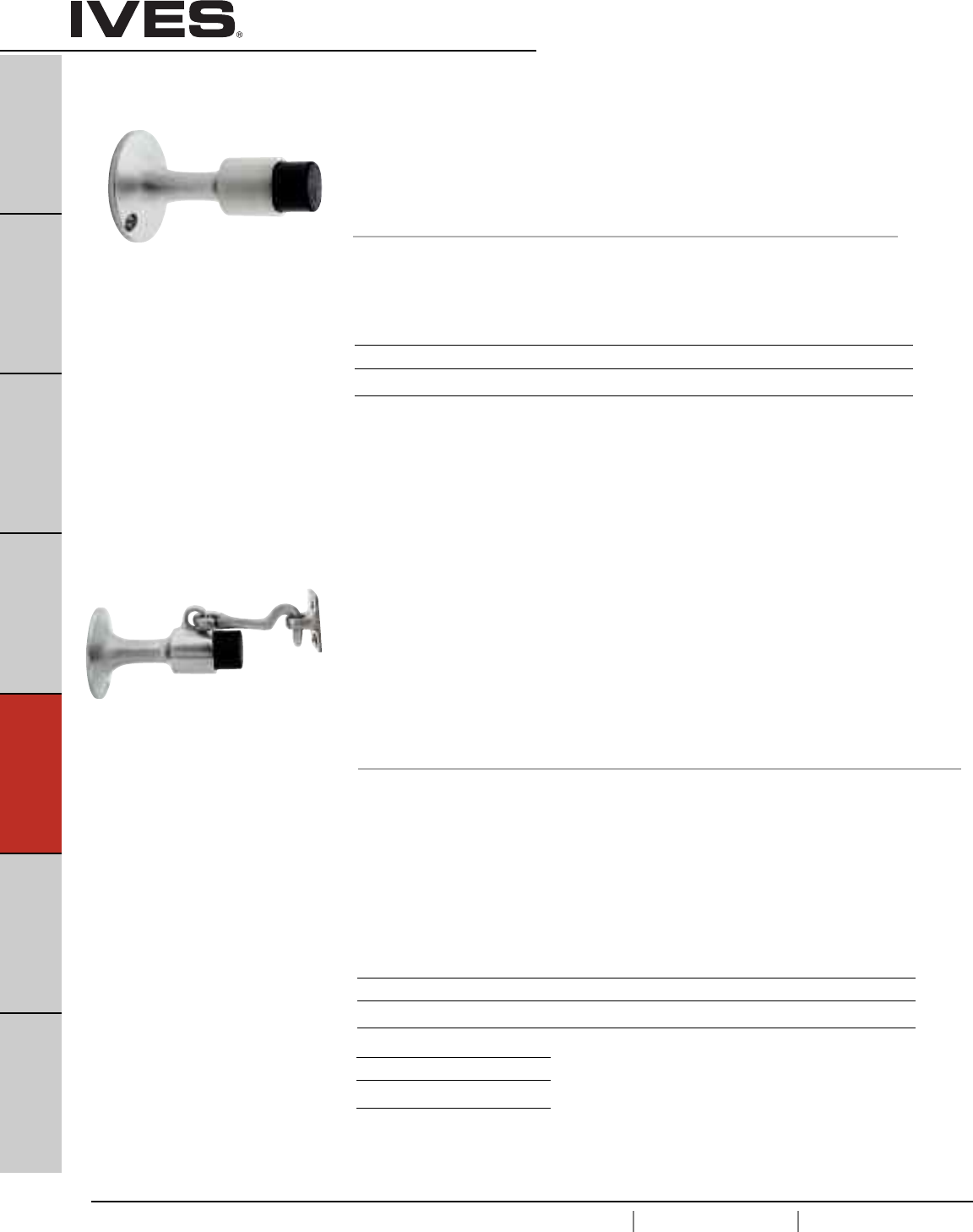
E14
USA 1.877.671.7011 Canada 1.905.403.1800 www.ives.ingersollrand.com
Wall Stops & Holders
B
Pulls & Plates
A
Hinges & Pivots
C
Flush Bolts & Coordinators
D
Latches, Catches & Bolts
E14
Stops
F
Exterior Hardware
G
Miscellaneous Hardware
WS445
WS449 Manual Wall Holder
• Constructed in cast of brass or aluminum.
• Unit functions as a stop but serves as a Hold-Open device when hook
is manually engaged in strike.
• Unit requires manual disengagement to release Hold-Open.
• Replaceable resilient, non-marring rubber tip.
WS445 is packed with expansion shield and lead shield for masonry type mounting.
WS449 is packed with wood screws for drywall mounting.
Dimensions
Base Diameter: 2-1/4"
Base Projection: 3-11/16"
Engaged Projection: 5-3/4"
Strike Height: 1-1/2"
Strike Width: 13/16"
Strike Projection: 13/16"
Finishes brass
Ives Number US3 US4 US10 US10B US15 US26 US26D
BHMA 605 606 612 613 619 625 626
WS445
Meets ANSI/BHMA 156.16, L11351 for brass.
WS449
Meets ANSI/BHMA 156.16, L11341 for brass
and L31341 for aluminum.
Finishes aluminum
Ives Number US28*
BHMA 628
* only available on WS449
WS443
WS447 Wall Stop
• Constructed in brass.
• Ideal for interior or exterior use.
• Replaceable non-marring rubber tip.
WS443 is packed with expansion shield and lead shield for masonry type mounting.
WS447 is packed with wood screws for drywall mounting.
Dimensions
Base Diameter: 2-1/4"
Overall Projection: 3-11/16"
Finishes brass
Ives Number US3 US4 US10 US10B US15 US26 US26D
BHMA 605 606 612 613 619 625 626
WS443
Meets ANSI/BHMA 156.16, L12021 for brass
and L32021 for aluminum.
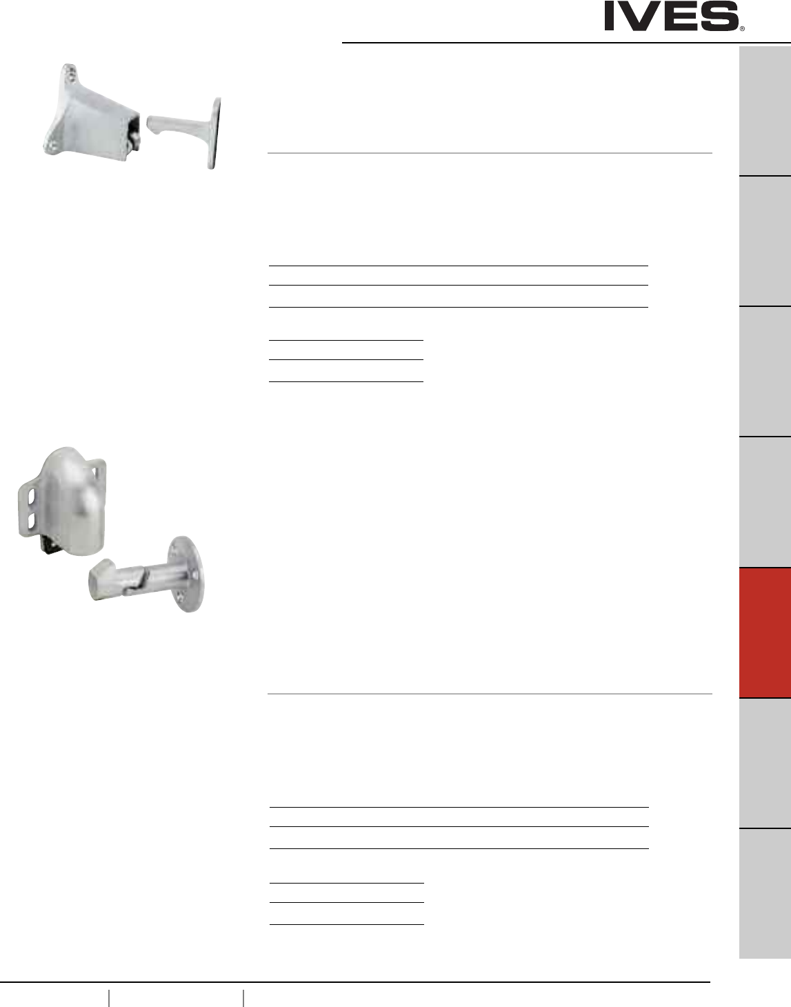
E15
USA 1.877.671.7011 Canada 1.905.403.1800 www.ives.ingersollrand.com
Automatic Wall Holders
B
Pulls & Plates
A
Hinges & Pivots
C
Flush Bolts & Coordinators
D
Latches, Catches & Bolts
E15
Stops
F
Exterior Hardware
G
Miscellaneous Hardware
WS40 Automatic Wall Holder
• Constructed of sturdy cast brass, or aluminum.
• Holder is mounted on wall and strike is mounted on door.
• Roller on holder rides up seats itself on strike, with a heavy duty bumper
pad deadening the sound and shock.
• Universal screw pack accommodates all types wall construction.
Dimensions
Base Height: 2"
Base Width: 2-1/2"
Base Projection: 2-1/4"
Engaged Projection: 3-1/2"
WS45
WS45X Automatic Wall Holder
• Constructed of cast brass, bronze or aluminum.
• Spring loaded roller rides up the face of the strike,
seating itself on the strike, holding the door firmly in the open position.
• A heavy rubber pad cushions the shock and absorbs the sound.
• With unit mounted on door and the strike on wall, vertical adjustment
is available on body.
• The strike is adjustable 45 degrees left or right, both adjustments easily
accomplished at time of installation or at a later date.
WS45 strike is furnished with wood screws for drywall mounting.
WS45X strike is furnished with a threaded stud and expansion shield
for masonry type mounting.
Dimensions
Base Height: 3-11/16" Strike Diameter: 2-3/8
Base Width: 3" Strike Projection: 3"
Base Projection: 2"
Engaged Projection: 3-7/16"
Meets ANSI/BHMA 156.16, L11291 for brass
and L31291 for aluminum.
WS45
Meets ANSI/BHMA 156.16, L11291 for brass
and L31291 for aluminum.
Finishes brass
Ives Number US3 US4 US10 US10B US26 US26D
BHMA 605 606 612 613 625 626
Finishes aluminum
Ives Number US28
BHMA 628
Finishes brass
Ives Number US3 US4 US10 US10B US26 US26D
BHMA 605 606 612 613 625 626
Finishes aluminum
Ives Number US28
BHMA 628
Strike Height: 2-1/16"
Strike Width: 3/4"
Strike Projection: 2"
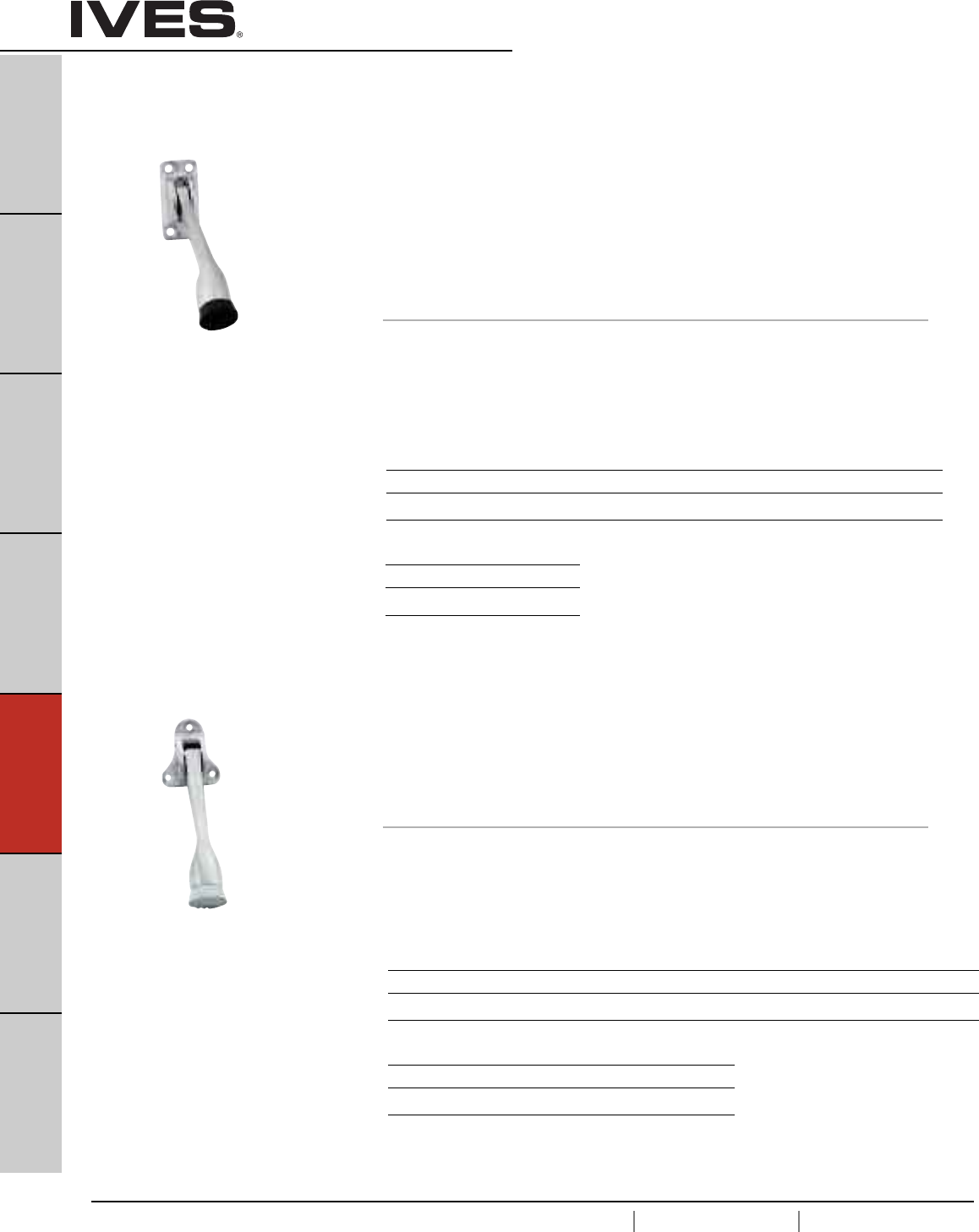
E16
USA 1.877.671.7011 Canada 1.905.403.1800 www.ives.ingersollrand.com
Kick Down Holders
B
Pulls & Plates
A
Hinges & Pivots
C
Flush Bolts & Coordinators
D
Latches, Catches & Bolts
E16
Stops
F
Exterior Hardware
G
Miscellaneous Hardware
FS452 Kick Down Holder
• Units provide simple hold and release, activated with a touch of the foot.
• Cast brass or aluminum construction.
• Stainless steel spring.
• Replaceable non-marring rubber shoes have corrugated bottoms to provide
secure grip.
• Shoes are easily replaced when worn. Shoe held on with screw.
• Packed with sheet metal screws.
FS452-4 has a door-to-floor clearance of 2" or less.
FS452-5 has a door-to-floor clearance up to 3".
Dimensions
FS452-4 Door-to-Floor Clearance: 2" or less FS452-5 Door-to-Floor Clearance: Up to 3"
FS452-4 Plate Height: 2-1/8" FS452-5 Plate Height: 2-1/8"
FS452-4 Plate Width: 1" FS452-5 Plate Width: 1"
FS455 Kick Down Holder
• Units provide simple hold and release, activated with a touch of the foot.
• Cast brass or aluminum construction.
• Replaceable non-marring rubber shoes have corrugated bottoms to provide
secure grip. When worn, shoes are easily replaced. Shoe held on with screws.
• Door-to-floor clearances of 2" or less.
Dimensions
Door-to-Floor Clearance: 2" or less
Plate Height: 1-3/4"
Plate Width: 1-3/4"
Meets ANSI/BHMA 156.16, L11383 for brass
and L31383 for aluminum.
Meets ANSI/BHMA 156.16, L11382 for brass
and L31382 for aluminum.
Finishes brass
Ives Number US3 US4 US10 US10B US15 US26 US26D
BHMA 605 606 612 613 619 625 626
Finishes aluminum
Ives Number US28*
BHMA 628
* available in 4" only
Finishes brass
Ives Number US3 US4 US5 US10 US10B US15 US26 US26D
BHMA 605 606 609 612 613 619 625 626
Finishes aluminum
Ives Number US3AL US5AL US10AL US27
BHMA 666 609 668 673
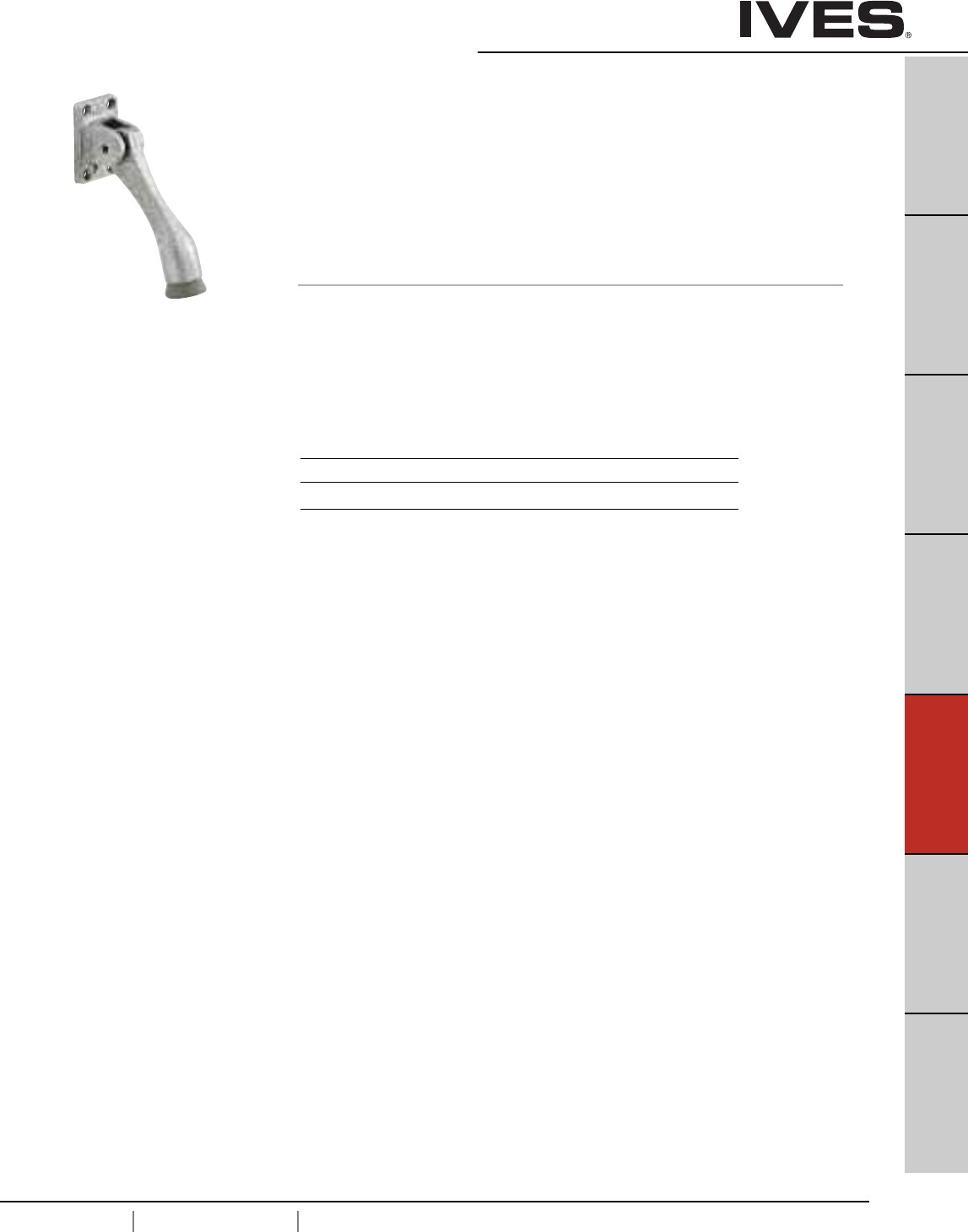
E17
USA 1.877.671.7011 Canada 1.905.403.1800 www.ives.ingersollrand.com
Kick Down Holders
B
Pulls & Plates
A
Hinges & Pivots
C
Flush Bolts & Coordinators
D
Latches, Catches & Bolts
E17
Stops
F
Exterior Hardware
G
Miscellaneous Hardware
FS544
FS555 Kick Down Holder
• Units provide an economical method to hold open doors.
• Cast of durable iron.
• Non-marring rubber shoes have corrugated bottoms to provide secure grip.
Rubber shoe is securely fastened with screw. When worn, shoes are easily
replaced.
FS544 for door-to-floor clearances of 2" or less
FS555 for door-to-floor clearances up to 3".
Dimensions
FS544
Door-to-Floor Clearance: 2" or less
Plate Height: 2-1/4"
Plate Width: 1-7/16"
FS544
Meets ANSI/BHMA 156.16, L11381
FS555
Meets ANSI/BHMA 156.16, L11391
Finishes
Ives Number SP4 SP10 SP28 SP313 SPBLK
BHMA 706 691 689 695 622
FS555
Door-to-Floor Clearance: Up to 3"
Plate Height: 2-1/4"
Plate Width: 1-7/16"
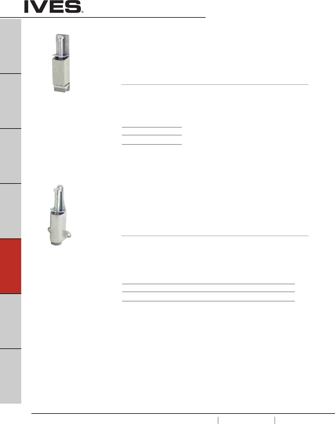
E18
USA 1.877.671.7011 Canada 1.905.403.1800 www.ives.ingersollrand.com
Plunger Type Door Holders
B
Pulls & Plates
A
Hinges & Pivots
C
Flush Bolts & Coordinators
D
Latches, Catches & Bolts
E18
Stops
F
Exterior Hardware
G
Miscellaneous Hardware
FS1153 Plunger Type Door Holder
• Provides a contemporary yet economical method of positive Hold-Open.
• Constructed in sturdy cast aluminum.
• Spring operated plunger activates with minimal pressure, releasing instantly
with a light tap on the plat-form lever.
• Provides a 1-5/8" throw for all types of doors.
• Ribbed non-marring rubber shoe is securely fastened to unit with a screw
and is easily replaced when worn.
Dimensions
Height: 6-1/4"
Width: 1-1/2"
Depth: 1-7/16"
Meets ANSI/BHMA 156.16, L31401.
Finishes
Ives Number US28
BHMA 628
FS1154 Plunger Type Door Holder
• Constructed from heavy-duty cast brass or bronze.
• Plunger and internal parts are plated steel and provides a 1-1/4" throw for
all types of doors.
• Plunger is easily activated with minimal pressure, releasing instantly with a
light tap on the platform lever.
• Round non-marring rubber shoe is securely fastened with a screw in flanged
cup to prevent movement or loss. When worn, shoes are easily replaced.
Dimensions
Height: 5-1/2"
Width: 2"
Depth: 1-1/4"
Meets ANSI/BHMA 156.16, L11401.
Finishes
Ives Number US3 US4 US10 US10B US26 US26D
BHMA 605 606 612 613 625 626
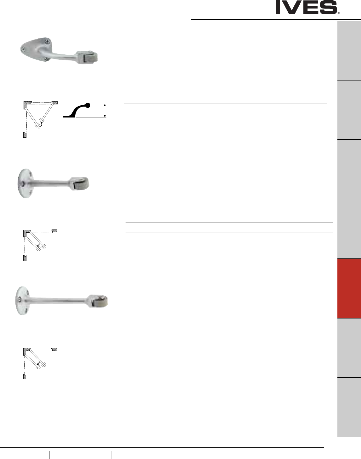
E19
USA 1.877.671.7011 Canada 1.905.403.1800 www.ives.ingersollrand.com
Roller Bumpers
B
Pulls & Plates
A
Hinges & Pivots
C
Flush Bolts & Coordinators
D
Latches, Catches & Bolts
E19
Stops
F
Exterior Hardware
G
Miscellaneous Hardware
RB470
RB471
RB472 Roller Bumpers
• Constructed in heavy-duty cast brass.
• RB470 used where two doors open against each other to
prevent damage to the doors or hardware.
• RB471 and RB472 are ideal for use in situations where doors
meet each other at approximate right angles (back to back).
• Replaceable rubber roller available.
Dimensions
RB470 Base Size: 1-11/16" x 2-1/4"
RB470 Arm Offset: 2-3/4"
RB470 Length: 5"
RB471 Base Diameter: 2"
RB471 Length: 4-1/2"
RB472 Base Diameter: 2"
RB472 Length: 6"
FS470
FS471
FS472
B
Offset
Finishes
Ives Number US3 US4** US10* US10B* US15* US26 US26D
BHMA 605 606** 612* 613* 619* 625 626
Meets ANSI/BHMA 156.16, L12212
Meets ANSI/BHMA 156.16, L12192
Meets ANSI/BHMA 156.16, L12202
* only available on RB472
** only available on RB471 and RB472
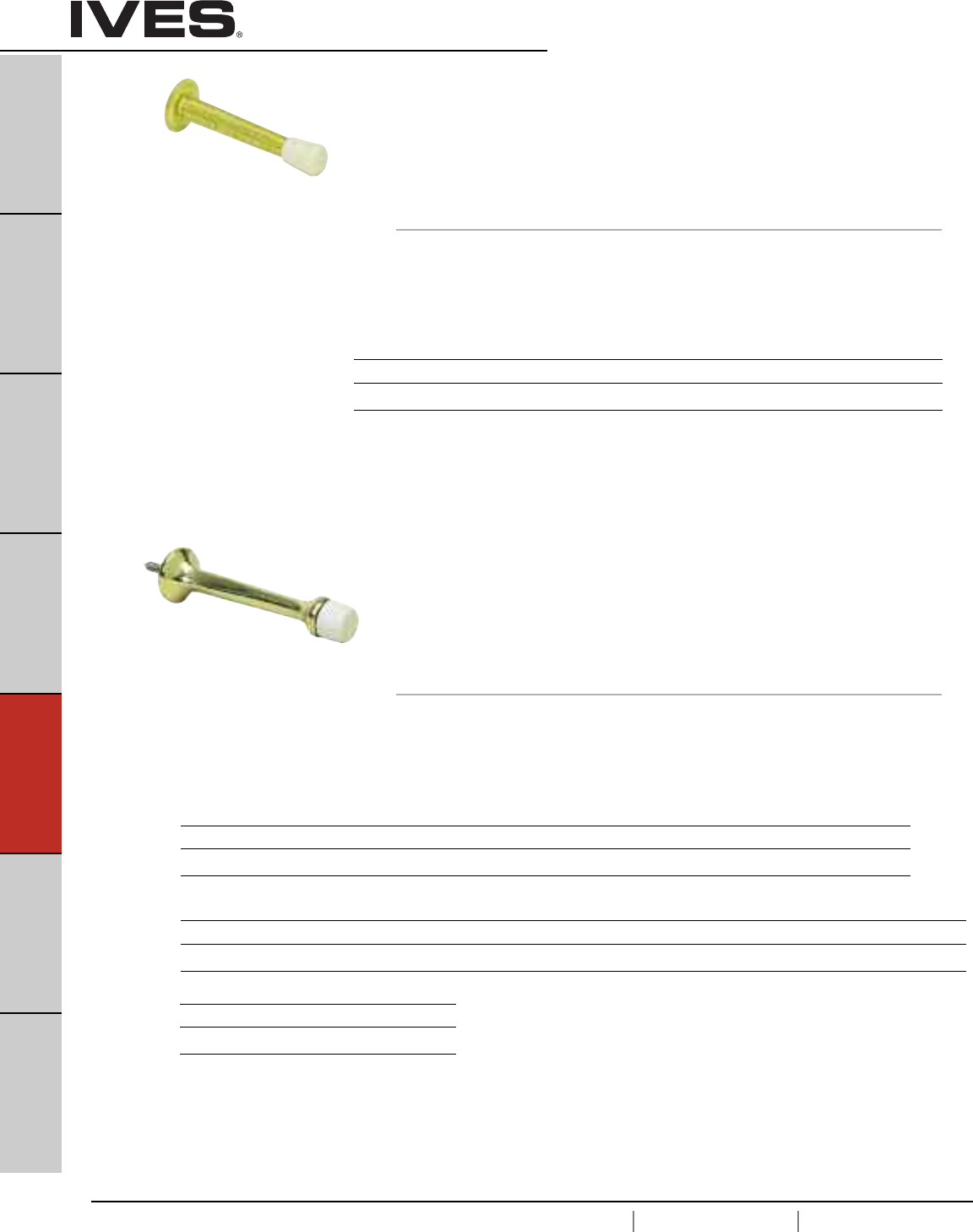
E20
USA 1.877.671.7011 Canada 1.905.403.1800 www.ives.ingersollrand.com
Residential Door Stops
B
Pulls & Plates
A
Hinges & Pivots
C
Flush Bolts & Coordinators
D
Latches, Catches & Bolts
E20
Stops
F
Exterior Hardware
G
Miscellaneous Hardware
060 Flexible Door Stops
061
• Utilizes heavy gauge spring to maintain rigid protections
• Simple to install - only a screwdriver required
•Made from burnished wrought steel
• Packed disassembled for quick installation
Replaceable white rubber tip available
Dimensions
Base Diameter: 1"
Tip Diameter: 19/16"
060 3" Projection
061 4" Projection
60 Base Door Stops
61
• Available in three sizes to accommodate varying areas of installation
and door trim dimensions
• Made from solid brass or aluminum
• 61 also available in epoxy colored aluminum
Replaceable white rubber tip available
Dimensions
60 3-3/4" Projection, Base Diameter: 1"
61 3-1/8" Projection on brass units, 3-3/16" Projection on aluminum units, Base Diameter: 7/8"
Tip Diameter: 5/8"
Finishes steel
Ives Finish F3 F5 F10 F10B F14 F15* F26D F-W**
BHMA 632 638 639 640 645 646 652
Finishes brass
Ives Finish B3 B4 B5 B10 B10B B15 B15A* B26 B26D B716**
BHMA 605 606 609 612 613 619 620 625 626
Finishes aluminum
Ives Finish A3 A5* A10* A10B A14 A15* A19* A92 A716* A-BLK A-W*
BHMA 666 668 703 669 670 A19 673
Finishes zinc
Ives Finish Z605* Z619* Z716*
BHMA
Meets ANSI/BHMA A156.16
* only available on 060
** only available on 061
* only available on 61
** only available on 61 Schlage Carded or slim package of 15
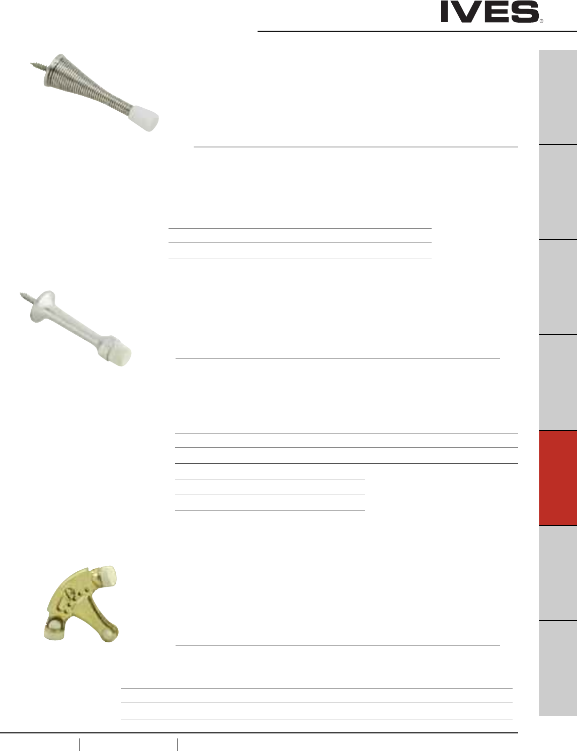
E21
USA 1.877.671.7011 Canada 1.905.403.1800 www.ives.ingersollrand.com
Residential Door Stops
B
Pulls & Plates
A
Hinges & Pivots
C
Flush Bolts & Coordinators
D
Latches, Catches & Bolts
E21
Stops
F
Exterior Hardware
G
Miscellaneous Hardware
64 Base Door Stop
• Base Door Stop features deluxe one-piece styling
• Easily screws into base
• Designed with square head to accommodate wrench or pliers when installing
• Made from solid brass or aluminum
Replaceable white rubber tip available
Dimensions
Base Diameter: 1"
Tip Diameter: 9/16"
Projection: 3-1/4"
69 Hinge Pin Door Stops
• For use on hinged doors where the installation of a standard door
stop is not desirable
• Positive slip proof adjustment
• Non-marring rubber tips
• Removable bushings accommodate 1/4" to 5/16" diameter hinge pins
• Easy installation—only a screwdriver required
• Made from burnished wrought steel
Replaceable white rubber tip available
Door Opening
70° to 100° Door Opening Adjustments
Finishes brass
Ives Finish B3 B4 B5 B10 B10B B15 B26 B26D
BHMA 605 606 609 612 613 619 625 626
Finishes aluminum
Ives Finish A3 A10B A92
BHMA 666 703 673
Finishes steel
Ives Finish F3 F5 F10 F10B F14 F15 F15A F26 F26D
BHMA 632 638 639 640 645 646 647 651 652
63 Flexible Door Stops
• Utilizes heavy gauge spring to maintain rigid protections
• Simple to install - only a screwdriver required
• Made from burnished wrought steel
•Packed disassembled for quick installation
Replaceable white rubber tip available
Dimensions
Base Diameter: 1"
Tip Diameter: 9/16"
Projection: 3"
Finishes steel
Ives Finish F605E F609E F619E F716 F-W
BHMA 632 638 646
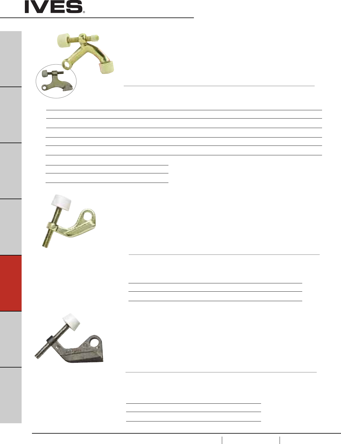
E22
USA 1.877.671.7011 Canada 1.905.403.1800 www.ives.ingersollrand.com
Residential Door Stops
B
Pulls & Plates
A
Hinges & Pivots
C
Flush Bolts & Coordinators
D
Latches, Catches & Bolts
E22
Stops
F
Exterior Hardware
G
Miscellaneous Hardware
Finishes zinc
Ives Finish Z605E Z609E Z613E Z619E Z625E Z-W
BHMA
Finishes zinc
Ives Finish Z605E Z613E Z619E Z625E
BHMA
Meets ANSI/BHMA 156.6, L12141 for brass
or bronze and L32141 for aluminum.
72 Hinge Pin Door Stops
• For use on hinged doors where the installation of a standard door stop
is not desirable
• Designed for narrow trim installation
• High quality rubber bumpers - shoulder on stud supports rubber through
entire body for engineered cushioning
• Removable bushings accommodate 1/4" to 5/16" diameter hinge pins
• Easy installation
• Made from solid brass, aluminum, or epoxy coated aluminum
Door Opening
85° to 125° Door Opening Adjustments
73 Hinge Pin Door Stops
• For use on hinged doors where the installation of a standard door stop
is not desirable
• Designed for narrow trim installation
• High quality rubber bumpers - shoulder on stud supports rubber through
entire body for engineered cushioning
• Removable bushings accommodate 1/4" to 5/16" diameter hinge pins
• Easy installation
• Made from solid brass, aluminum, or epoxy coated aluminum
Door Opening
85° to 125° Door Opening Adjustments
Door Saver
Door Saver
70 Hinge Pin Door Stops
• For use on hinged doors where the installation of a standard door stop
is not desirable
• Designed for narrow trim installation
• High quality rubber bumpers - shoulder on stud supports rubber through
entire body for engineered cushioning
• Removable bushings accommodate 1/4" to 5/16" diameter hinge pins
• Easy installation
• Made from solid brass, aluminum, or epoxy coated aluminum
Replaceable white rubber tip available
Door Opening
85° to 125° Door Opening Adjustments
Finishes brass
Ives Finish B3 B4 B5 B10 B10B B15 B15A* B19 B26 B26D B716*
BHMA 605 606 609 612 613 619 620 622 625 626
Finishes aluminum
Ives Finish A3 A4 A5 A10 A10B A14 A15 A92 A716 A-W A-BLK
BHMA 666 667 668 716 669 670 673
Finishes zinc
Ives Finish Z605E Z406E** Z619E** Z716E
BHMA
* only available in Schlage Carded or Slim-Pak of 25
** only available in Schlage Carded
70-Zinc
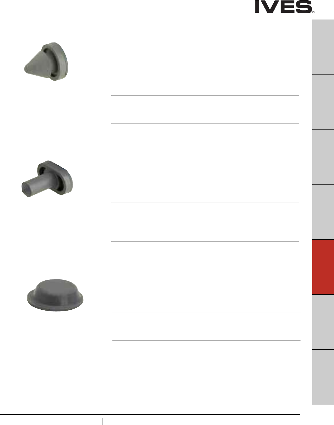
E23
USA 1.877.671.7011 Canada 1.905.403.1800 www.ives.ingersollrand.com
Door Silencers
B
Pulls & Plates
A
Hinges & Pivots
C
Flush Bolts & Coordinators
D
Latches, Catches & Bolts
E23
Stops
F
Exterior Hardware
G
Miscellaneous Hardware
SR64 Door Silencer
• For use on metal frames featuring pneumatic design that, once installed,
forms an air pocket to absorb shock and reduce noise of door closing.
• Tamper-proof once installed on the frame.
• Proper installation also eliminates door rattle and provides constant
tension for door latches or locks.
Packed in bags of 100.
Grey Available in bulk pack of 2500.
Each bag has an installation tool included.
Dimensions
Diameter: 1/2"
Thickness: 1/8"
Finishes
GRY, TAN
SR65 Door Silencer
• For use on wood frames, also feature pneumatic design to cushion shock
and absorb noise.
• To prevent removal, a small brad should be driven into stop strip
and through stem of silencer, as shown in the detail.
Packed in bags of 100.
Dimensions
Height: 3/4"
Diameter: 3/8"
Thickness: 1/8"
Finishes
GRY
SR66 Door Silencer
• Self Adhesive Rubber Silencers.
• Economical installation requires no drilling of frames.
Packed two sheets of 50 (100 minimum).
Dimensions
Diameter: 1/2"
Thickness: 1/8"
Finishes
BRN, GRY, WHT
Meets ANSI/BHMA 156.16, L03011.
Meets ANSI/BHMA 156.16, L03021

E24
USA 1.877.671.7011 Canada 1.905.403.1800 www.ives.ingersollrand.com
Notes
B
Pulls & Plates
A
Hinges & Pivots
C
Flush Bolts & Coordinators
D
Latches, Catches & Bolts
E24
Stops
F
Exterior Hardware
G
Miscellaneous Hardware
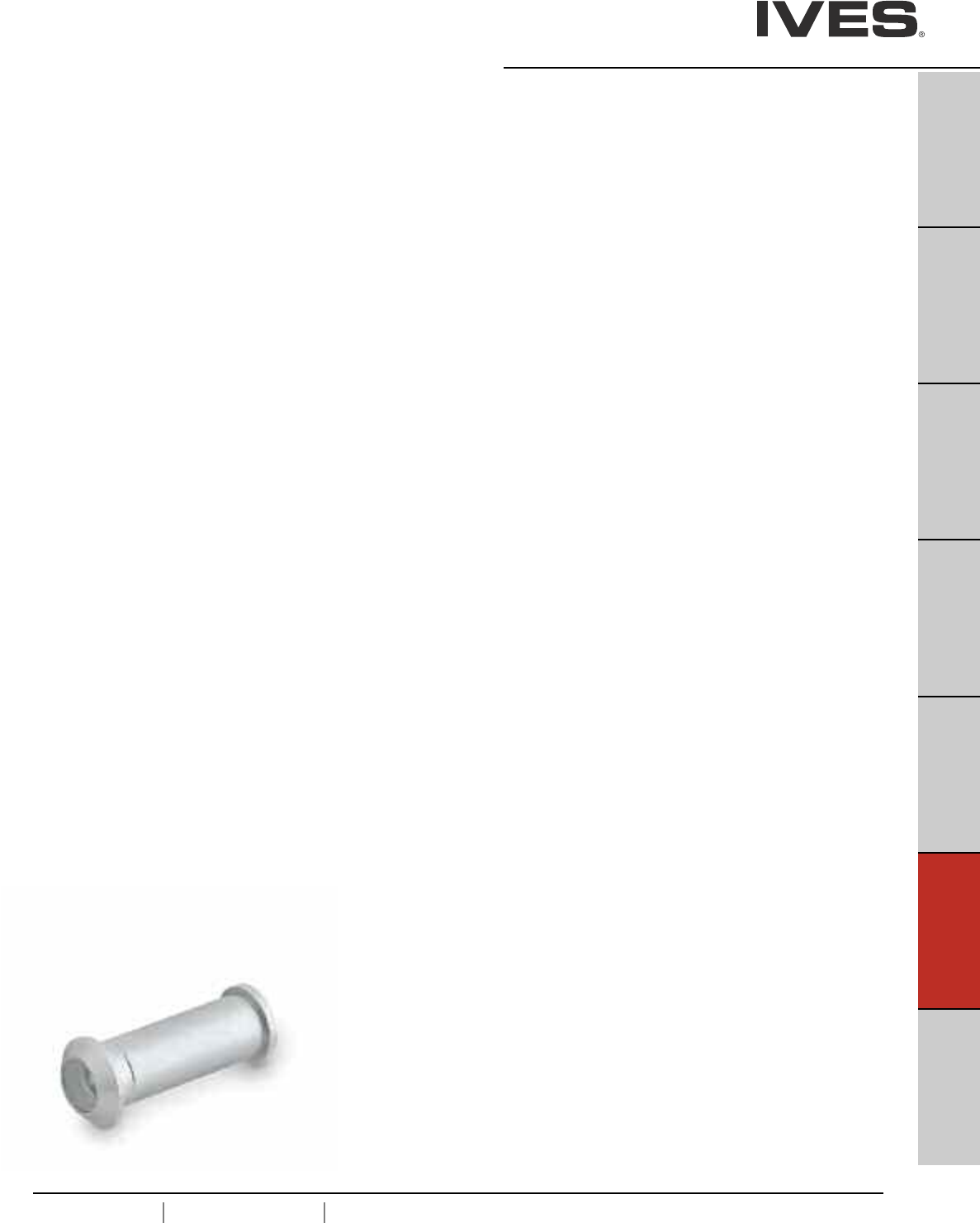
F1
USA 1.877.671.7011 Canada 1.905.403.1800 www.ives.ingersollrand.com
Exterior Hardware
B
Pulls & Plates
A
Hinges & Pivots
C
Flush Bolts & Coordinators
D
Latches, Catches & Bolts
E
Stops
F1
Exterior Hardware
G
Miscellaneous Hardware
Table Of Contents
Lock Guards page
LG1, LG7 Lock Guard . . . . . . . . . . . . . . . . . . . . . . . . . . . . . . . . . . . . . . . .F2
LG10 Lock Guard . . . . . . . . . . . . . . . . . . . . . . . . . . . . . . . . . . . . . . . . . . .F2
LG11 Lock Guard . . . . . . . . . . . . . . . . . . . . . . . . . . . . . . . . . . . . . . . . . . .F3
LG12 Lock Guard . . . . . . . . . . . . . . . . . . . . . . . . . . . . . . . . . . . . . . . . . . .F3
LG13 Lock Guard . . . . . . . . . . . . . . . . . . . . . . . . . . . . . . . . . . . . . . . . . . .F4
LG14 Lock Guard . . . . . . . . . . . . . . . . . . . . . . . . . . . . . . . . . . . . . . . . . . .F4
Viewers
U696 One-way Viewer . . . . . . . . . . . . . . . . . . . . . . . . . . . . . . . . . . . . . . .F5
698, U698 One-way Viewer . . . . . . . . . . . . . . . . . . . . . . . . . . . . . . . . . . .F5
700, U700 One-way Viewer . . . . . . . . . . . . . . . . . . . . . . . . . . . . . . . . . . .F6
701, U701 One-way Viewer . . . . . . . . . . . . . . . . . . . . . . . . . . . . . . . . . . .F6
Door Knockers
3107 Door Knocker . . . . . . . . . . . . . . . . . . . . . . . . . . . . . . . . . . . . . . . . .F7
3125 Door Knocker . . . . . . . . . . . . . . . . . . . . . . . . . . . . . . . . . . . . . . . . .F7
Letter Box
620 Letter Box Plate . . . . . . . . . . . . . . . . . . . . . . . . . . . . . . . . . . . . . . . .F8
601 Letter Box Sleeve . . . . . . . . . . . . . . . . . . . . . . . . . . . . . . . . . . . . . . .F8
Door Numbers
02-30 Door Numbers . . . . . . . . . . . . . . . . . . . . . . . . . . . . . . . . . . . . . . . .F9
Storm and Screen Door
980 Storm Door Latch . . . . . . . . . . . . . . . . . . . . . . . . . . . . . . . . . . . . . . .F9
25 Screen Door Pull . . . . . . . . . . . . . . . . . . . . . . . . . . . . . . . . . . . . . . . .F10
Crash Stop
CS115 Crash Stop . . . . . . . . . . . . . . . . . . . . . . . . . . . . . . . . . . . . . . . . .F10
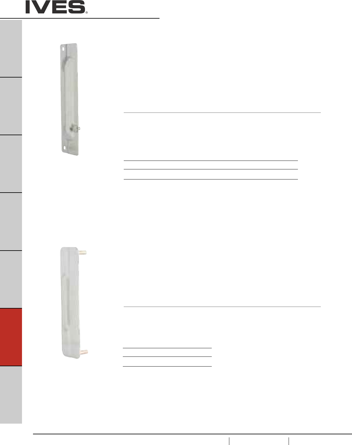
F2
USA 1.877.671.7011 Canada 1.905.403.1800 www.ives.ingersollrand.com
Lock Guards
B
Pulls & Plates
A
Hinges & Pivots
C
Flush Bolts & Coordinators
D
Latches, Catches & Bolts
E
Stops
F2
Exterior Hardware
G
Miscellaneous Hardware
LG1 Lock Guard
LG7 • Units are non-handed and incorporate security frame pin to
prevent separation of the door and frame. LG7 does not incorporate the
security frame pin
• Unit covers the latch bolt area of the door and lock, thereby providing
added protection from burglars, vandals or normal abuse.
• Ideal for use with mortise or cylindrical locks.
• Easy installation.
• Through bolted with carriage bolts and nuts.
• Available in a variety of materials, 13 gauge stainless steel,
12 gauge steel and brass material.
Dimensions
3" Wide x 11-1/2" High
Bolt center to center: 10-1/2"
LG10 Lock Guard
• Ideally suited for use with rose or escutcheon 2-3/4" wide or less.
• For use with Type 86 Mortise and Type 161 Cylindrical Locks
(ANSI 156.13 Series 1000 and ANSI 156.2 Series 4000).
• No exposed fasteners on face of unit.
• Unique design provides maximum security, virtually eliminating the
opening between door and frame at the latch point.
• Available in 13 Gauge Stainless Steel or 12 Gauge Steel.
Dimensions
2-1/2" Wide x 9-1/2" High
Stud center to center: 8-1/2"
Finishes
Ives Number USP* US2G* US4* US10* US32D SP313*
BHMA 600 603 606 612 630 695
* not available on LP7
Finishes
Ives Number USP US32D
BHMA 600 630
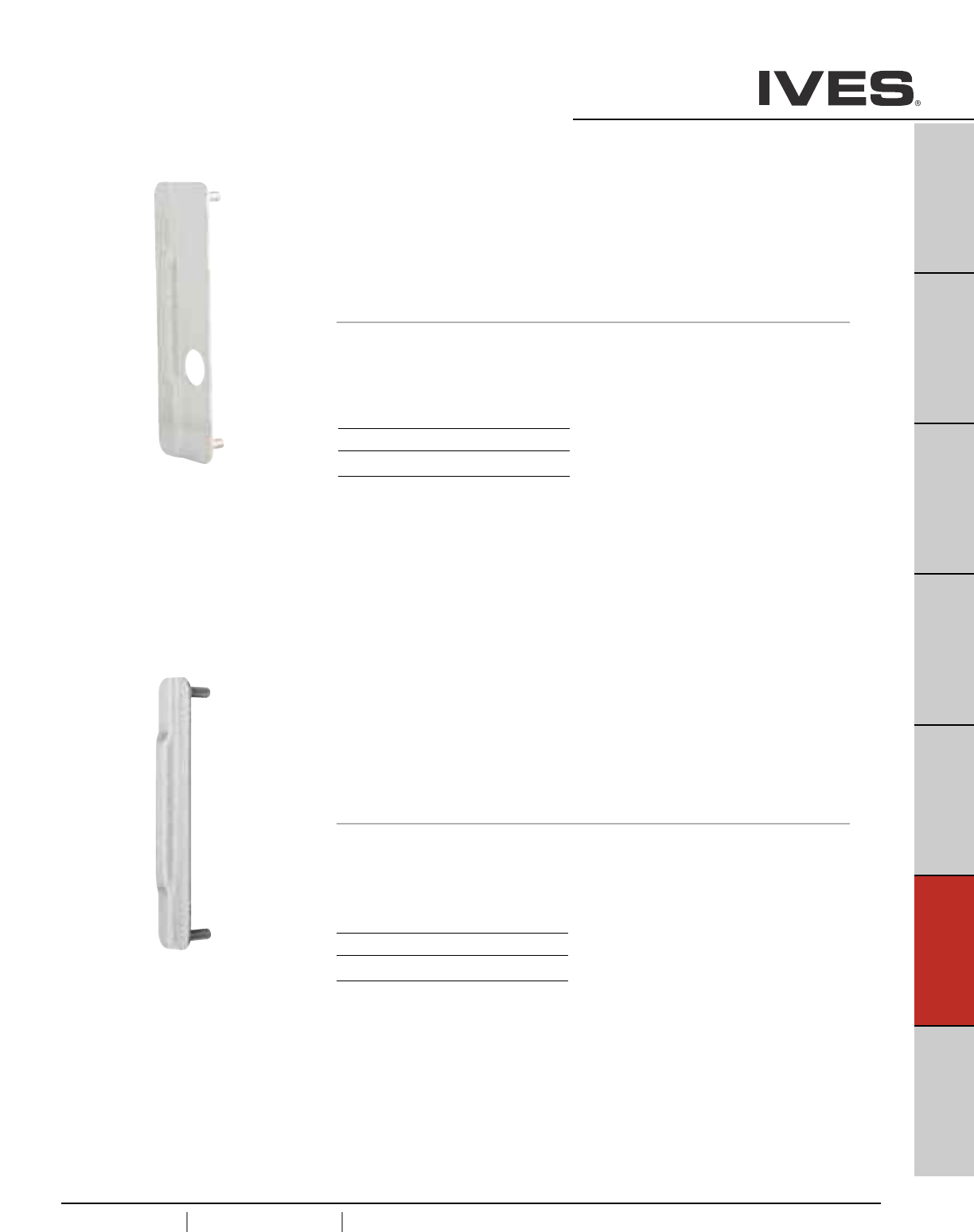
F3
USA 1.877.671.7011 Canada 1.905.403.1800 www.ives.ingersollrand.com
Lock Guards
B
Pulls & Plates
A
Hinges & Pivots
C
Flush Bolts & Coordinators
D
Latches, Catches & Bolts
E
Stops
F3
Exterior Hardware
G
Miscellaneous Hardware
LG11 Lock Guard
•Designed for use on aluminum doors with latch-type locks
or doors equipped with electric strikes.
• Unit is Handed - Specify left or right hand when ordering.
• No exposed fasteners on face of unit.
• Unique design provides maximum security, virtually eliminating the
opening between door and frame at latch point.
• Available in 13 Gauge Stainless Steel or 12 Gauge Steel.
Dimensions
2-1/2" Wide x 9-1/2" High
Stud center to center: 8-1/2"
LG12 Lock Guard
• Narrow design unit for use on rose or escutcheon 3-1/2" or less.
• For use with Type 86 Mortise and Type 161 Cylinder Locks
(ANSI 156.13 Series 1000 and ANSI 156.2 Series 4000).
• No exposed fasteners on face of unit.
• Unique design provides maximum security, virtually eliminating the opening
between door and frame at the latch point.
• Available in 13 Gauge Stainless Steel or 12 Gauge Steel
Dimensions
1-1/2" Wide x 9-1/2" High
Stud center to center: 8-1/2”
Finishes
Ives Number US32D SP313
BHMA 630 695
Finishes
Ives Number USP US32D
BHMA 600 630
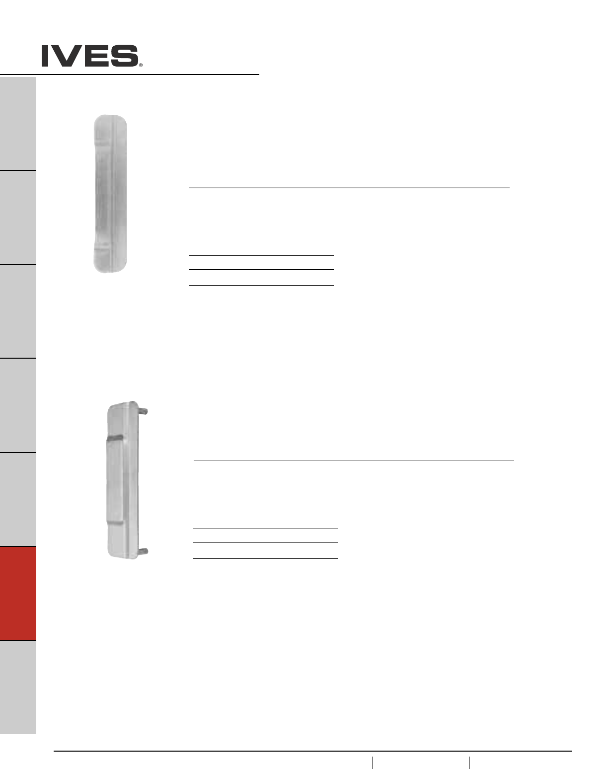
F4
USA 1.877.671.7011 Canada 1.905.403.1800 www.ives.ingersollrand.com
Lock Guards
B
Pulls & Plates
A
Hinges & Pivots
C
Flush Bolts & Coordinators
D
Latches, Catches & Bolts
E
Stops
F4
Exterior Hardware
G
Miscellaneous Hardware
LG14 Lock Guard
• Narrow design unit for use on rose or escutcheon 3-1/2" or less.
• For use with Von Duprin 6210 and 6211 electric strike.
• No exposed fasteners on face of unit.
• Unique design provides maximum security.
• Available in 13 Gauge Stainless Steel
Dimensions
2-9/16" Wide x 9-1/2" High
Stud center to center: 8-1/2"
LG13 Lock Guard
•Designed for use on all Type 161 Cylindrical Locks (ANSI 156.2 Series 2000)
Monolock and Unilock.
• No exposed fasteners on face of unit.
• Unique design provides maximum security, virtually eliminating the
opening between door and frame at latch point.
• Available in 13 Gauge Stainless Steel or 12 Gauge Steel.
Dimensions
1-1/2" Wide x 7" High
Stud center to center: 4-1/2"
Finishes
Ives Number USP US32D
BHMA 600 630
Finishes
Ives Number US32D
BHMA 630
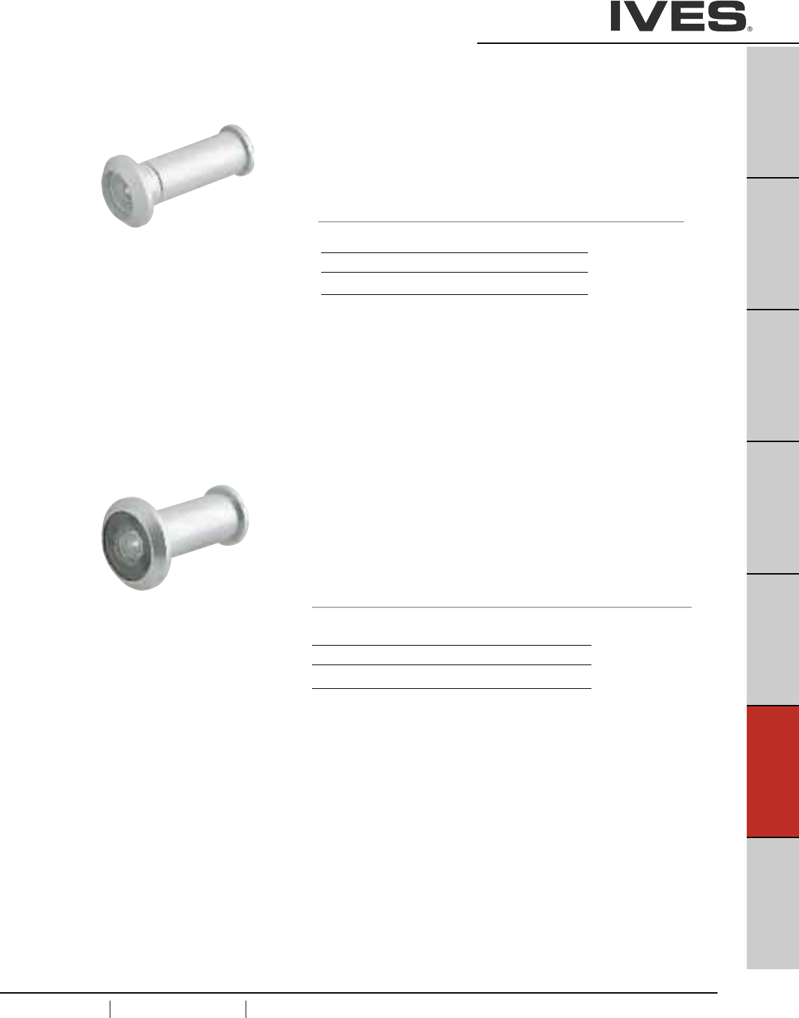
F5
USA 1.877.671.7011 Canada 1.905.403.1800 www.ives.ingersollrand.com
Viewers
B
Pulls & Plates
A
Hinges & Pivots
C
Flush Bolts & Coordinators
D
Latches, Catches & Bolts
E
Stops
F5
Exterior Hardware
G
Miscellaneous Hardware
U696 One-Way Viewer
• 150° Angle of View.
• For doors 1-3/8" to 2-1/16" thick.
• Secure, tamper-resistant.
• Solid brass body; glass lens.
• Simple installation — only a 1/2" hole required.
• Suggested installation height: 60" from floor.
• Trim washer available, 3/4" x .032" thick.
698
U698 One-Way Wide Angle Viewer
• 190° Angle of View.
• Lens projects 1/4" from face of door.
• 4 optical glass lenses.
• For doors 1-3/8" to 2-1/8" thick.
• Solid brass body and barrel.
• Simple installation — only a 9/16" hole required.
• Suggested installation height: 60" from floor.
Meets ANSI/BHMA A156.16 L23222
UL Listed 90 minute fire doors
Finishes
Ives Number B4 B10B B26D
BHMA 606 613 626
Finishes
Ives Number B3 B15** B26D B716*
BHMA 605 619 626
* not available on U698
** only available in Schlage Carded
698 meets ANSI/BHMA A156.16 L23172
U698 meets ANSI/BHMA A156.16 L23222
U698 is UL Listed 90 minute fire doors
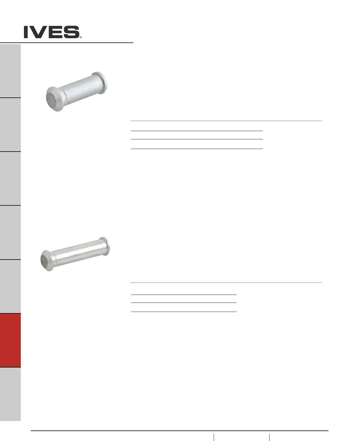
F6
USA 1.877.671.7011 Canada 1.905.403.1800 www.ives.ingersollrand.com
Viewers
B
Pulls & Plates
A
Hinges & Pivots
C
Flush Bolts & Coordinators
D
Latches, Catches & Bolts
E
Stops
F6
Exterior Hardware
G
Miscellaneous Hardware
700
U700 One-Way Viewer
• 120° Angle of View.
•For doors 1-3/8" to 2-1/16" thick.
• Secure, tamper-resistant.
• Solid brass body; glass lens.
• Simple installation—only a 1/2" hole required.
• Suggested installation height: 60" from floor.
• Trim washer available, 3/4" x .032" thick.
701
U701 One-Way Viewer
• 120° Angle of View.
• For doors 2-1/8" to 2-5/8" thick.
• Secure, tamper-resistant.
• Solid brass body; glass lens.
• Simple installation—only a 1/2" hole required.
• Suggested installation height: 60" from floor.
• Trim washer available, 3/4" x .032" thick.
700 meets ANSI/BHMA A156.16 L23173
U700 meets ANSI/BHMA A156.16 L23222
U700 is UL Listed 90 minute fire doors
701 meets ANSI/BHMA A156.16 L23173
U701 meets ANSI/BHMA A156.16 L23222
U701 is UL Listed 90 minute fire doors.
Finishes
Ives Number B3** B4 B10B* B26D
BHMA 605 606 613 626
* not available on U700
** only available on 700 in Schlage Carded
Finishes
Ives Number B4 B10B B26D
BHMA 606 613 626
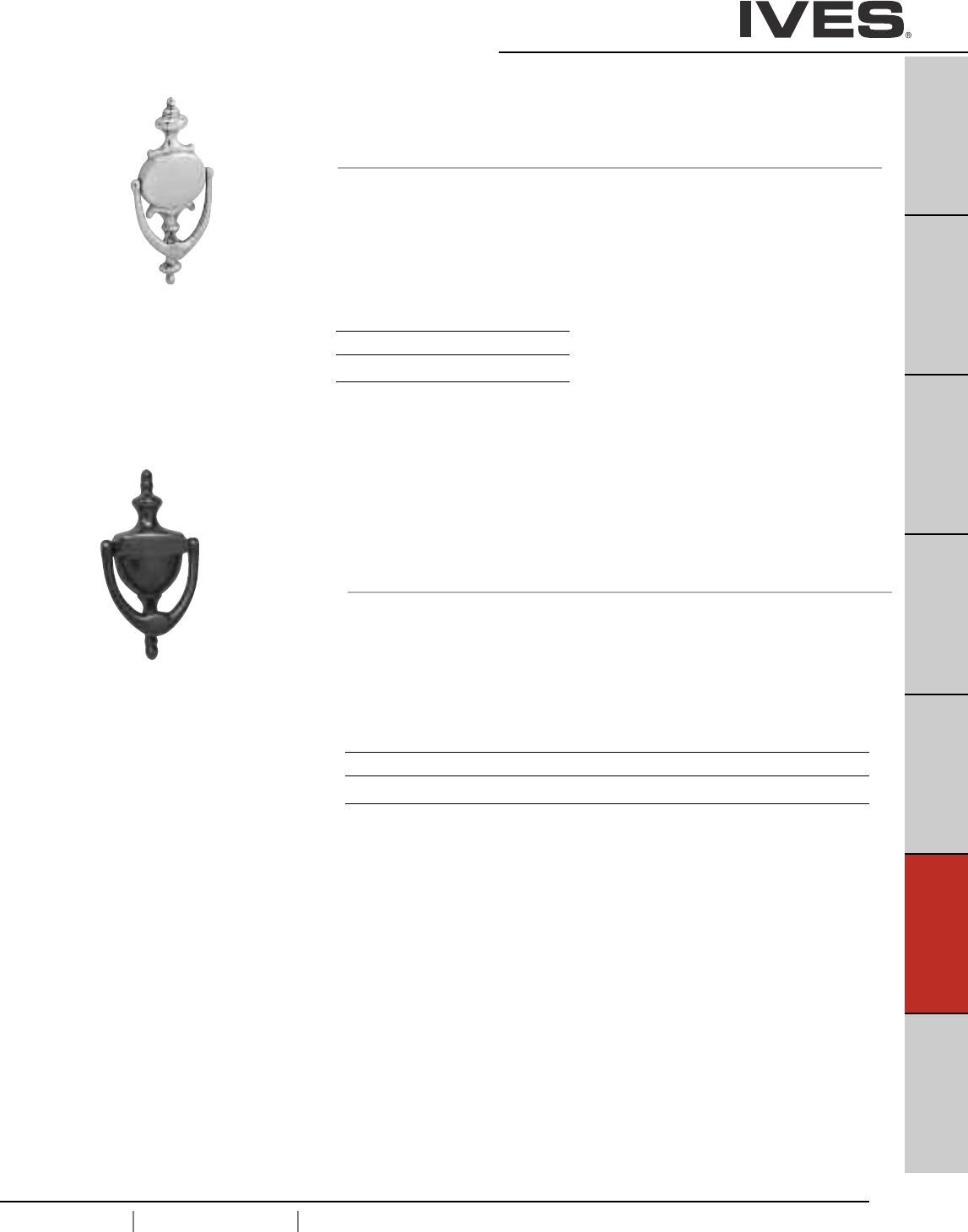
F7
USA 1.877.671.7011 Canada 1.905.403.1800 www.ives.ingersollrand.com
Door Knockers
B
Pulls & Plates
A
Hinges & Pivots
C
Flush Bolts & Coordinators
D
Latches, Catches & Bolts
E
Stops
F7
Exterior Hardware
G
Miscellaneous Hardware
02-3125 Knocker Only
02-31251U Knocker with U700 Viewer
02-31252U Knocker with U701 Viewer
• Knocker made from forged brass.
• 02-31251 and 02-31251U for door thickness 7/8" – 1-9/16"
• 02-31252 and 02-31252U for door thickness 1-5/8" – 2-1/8"
Dimensions
Length: 5-15/16"
Width: 3"
Projection: 1-1/16"
Mounting Hole Center-to-Center: 3-15/16"
Meets ANSI/BHMA A156.16 L23161
Finishes
Ives Number B3 B5 B15 B15A* B26 B26D 716
BHMA 605 609 619 620 625 626
* not available on viewer, only available in Schlage Carded
Only B3, B15, B26D and 716 knockers are available with viewer. B3 is furnished with B4
(606) viewer, 716 is furnished with B10B viewer, B15 (619) is furnished with a 636 viewer.
Meets ANSI/BHMA A156.16 L23151
02-3107 Knocker Only
• Knocker made from forged brass.
• Only available in Schlage Carded pak
Dimensions
Length: 8-1/2"
Width: 4-1/8"
Projection: 1"
Mounting Hole Center-to-Center: 5"
Finishes
Ives Number B605 B19
BHMA 605 619
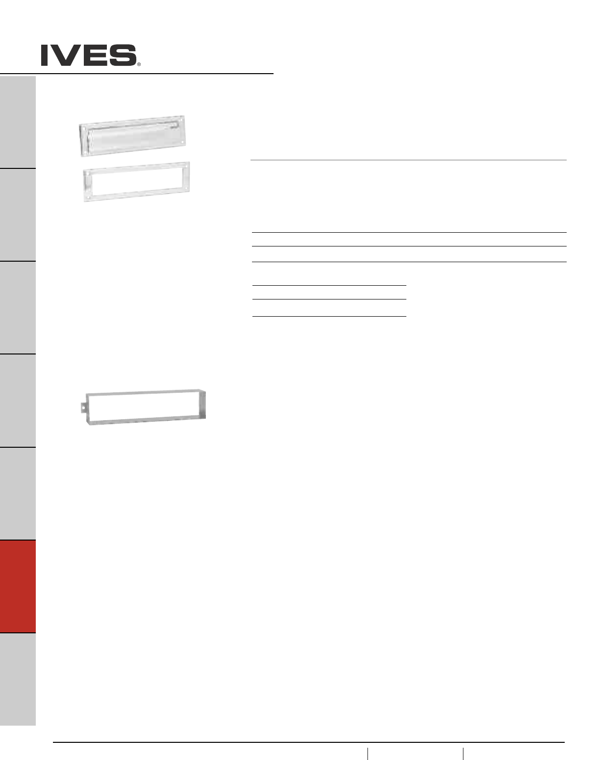
F8
USA 1.877.671.7011 Canada 1.905.403.1800 www.ives.ingersollrand.com
Door Knockers
B
Pulls & Plates
A
Hinges & Pivots
C
Flush Bolts & Coordinators
D
Latches, Catches & Bolts
E
Stops
F8
Exterior Hardware
G
Miscellaneous Hardware
Finishes brass
Ives Number B3 B5 B15 B15A* B26 B26D B716
BHMA 605 609 619 620 625 626
Finishes aluminum
Ives Number PA28
BHMA 628
* not available in U700 Schlage Carded
620 Magazine Size Letter Box Plate with
Standard (Open) Back Plate
• Spring-loaded front plate
• Sex Bolt mounting available, order separately 09-355 – finish.
Dimensions
Overall Size: 13" Wide x 3-9/16" High
Plate Opening: 11" x 2" High
601 Sleeve for use with Letter Box Plate
• Made of stainless steel.
• For 1-3/4" hollow core doors.
Meets ANSI/BHMA A156.16 L26031
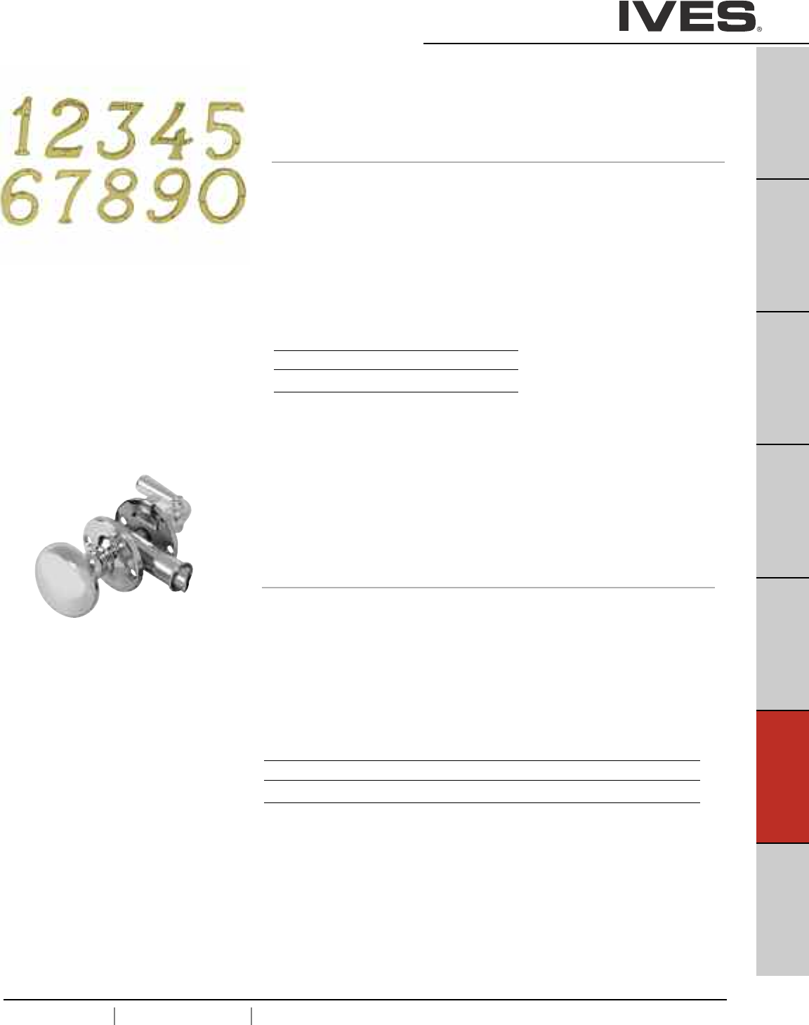
F9
USA 1.877.671.7011 Canada 1.905.403.1800 www.ives.ingersollrand.com
House Numbers
B
Pulls & Plates
A
Hinges & Pivots
C
Flush Bolts & Coordinators
D
Latches, Catches & Bolts
E
Stops
F9
Exterior Hardware
G
Miscellaneous Hardware
Finishes brass
Ives Number B3 B15 B716
BHMA 605 619
SC2 - 30 X 6 Heritage House Number
• Made from solid brass.
Schlage Carded
0 - 3006
1 - 3016
2 - 3026
3 - 3036
4 - 3046
Dimensions
Height: 4"
Finishes brass
Ives Number B3 B5 B10B B15 B19 B26 B26D
BHMA 605 609 613 619 622 625 626
980 Storm Door Latch
• For wood storm doors 7/8" to 1-1/8" thick.
• Reversible: fits right or left hand, inswinging or outswinging doors.
• Security lock feature operates from inside rose.
• Solid brass safety strike assures latching and is designed to
compensate for air pressure build-up between doors.
• Made from wrought brass.
Dimensions
Backset: 1-3/4"
Rose Diameter: 1-7/8"
Knob Diameter: 1-3/4"
Knob Projection: 2"
Lever Length: 1-3/4"
Lever Projection: 1-7/8"
5 - 3056
6 - 3066
7 - 3076
8 - 3086
9 - 3096
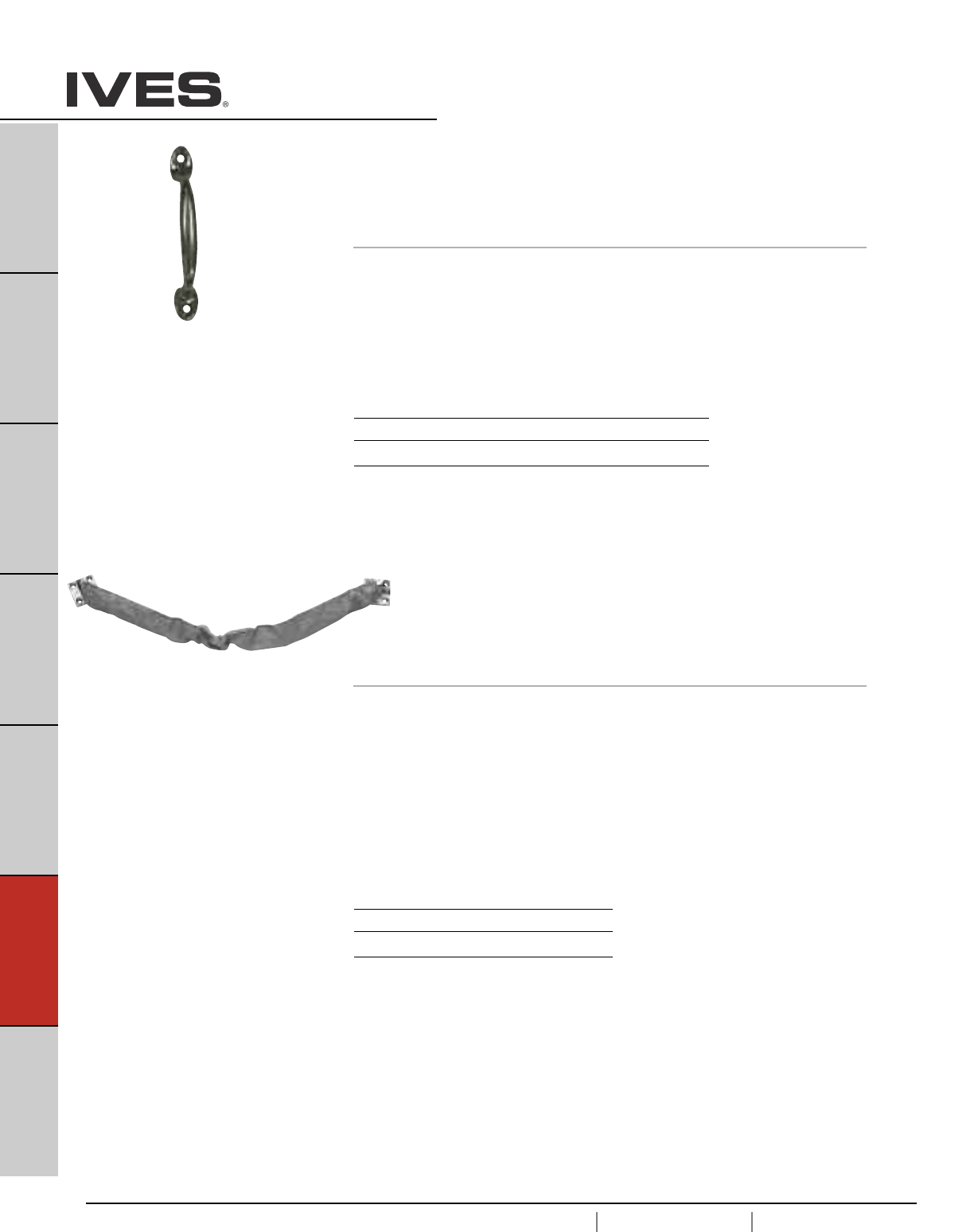
F10
USA 1.877.671.7011 Canada 1.905.403.1800 www.ives.ingersollrand.com
Crash Stops
B
Pulls & Plates
A
Hinges & Pivots
C
Flush Bolts & Coordinators
D
Latches, Catches & Bolts
E
Stops
F10
Exterior Hardware
G
Miscellaneous Hardware
25 Screen Door Pull
• Cast aluminum or epoxy-coated alumimum
•Also used as a window lift, drawer or utility pull
Dimensions
Length 4-7/8"
Projection 1-5/32"
Mounting holes 4-1/8" center to center
Meets ANSI/BHMA A156.16, L12231,
Finishes
Ives Number A3 A92 A-W A-B
BHMA 666 673
CS115 Crash Stop
• Specially designed for full-size exterior doors.
• Tear resistant, grey vinyl cover.
• Heavy duty compression spring assembled to both ends of chain
and end brackets.
• Packed with sheet metal screws.
• Cast Brass brackets with solid, welded steel chain.
• Optional sex bolt mounting available in US26D (626) only.
Dimensions
Bracket Size: 1-9/16" x 1-9/16"
Available Lengths:
20-1/2" — Recommended for 30" Door Width (Product No. CS115-20)
25-1/2" — Recommended for 36" Door Width (Product No. CS115-25)
30-1/2" — Recommended for 42" Door Width (Product No. CS115-30)
Meets ANSI/BHMA A156.16, L12231,
Finishes
Ives Number US10B US26D
BHMA 613 626
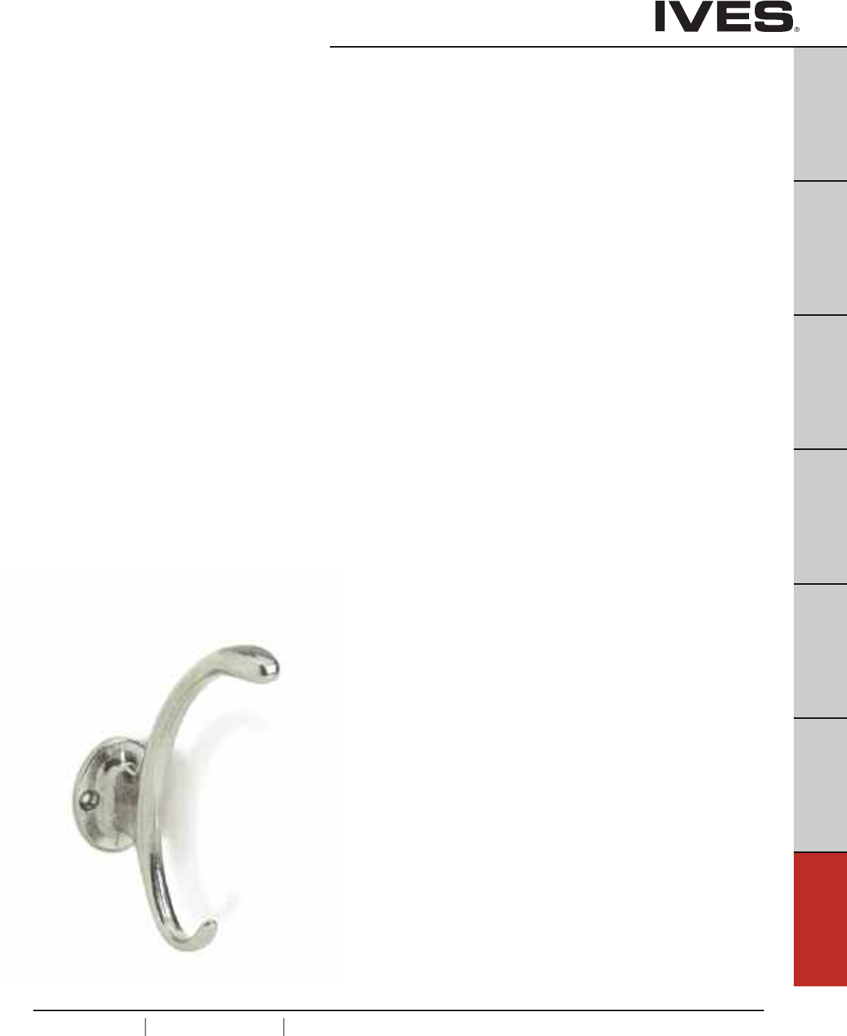
G1
USA 1.877.671.7011 Canada 1.905.403.1800 www.ives.ingersollrand.com
Miscellaneous Door Hardware
B
Pulls & Plates
A
Hinges & Pivots
C
Flush Bolts & Coordinators
D
Latches, Catches & Bolts
E
Stops
F
Exterior Hardware
G1
Miscellaneous Hardware
Table Of Contents
page
Hooks & Brackets
059 Handrail Bracket . . . . . . . . . . . . . . . . . . . . . . . . . . . . . . . . . . . . . . . . .G2
59 Handrail Bracket . . . . . . . . . . . . . . . . . . . . . . . . . . . . . . . . . . . . . . . . . .G2
159 Handrail Bracket . . . . . . . . . . . . . . . . . . . . . . . . . . . . . . . . . . . . . . . . .G2
405 Coat & Hat Hook . . . . . . . . . . . . . . . . . . . . . . . . . . . . . . . . . . . . . . . .G3
571 Coat & Hat Hook . . . . . . . . . . . . . . . . . . . . . . . . . . . . . . . . . . . . . . . .G3
572 Coat & Hat Hook . . . . . . . . . . . . . . . . . . . . . . . . . . . . . . . . . . . . . . . .G3
574 Coat & Hat Hook . . . . . . . . . . . . . . . . . . . . . . . . . . . . . . . . . . . . . . . .G4
575 Coat & Hat Hook . . . . . . . . . . . . . . . . . . . . . . . . . . . . . . . . . . . . . . . .G4
580 Ceiling Hook . . . . . . . . . . . . . . . . . . . . . . . . . . . . . . . . . . . . . . . . . . . .G4
581 Wardrobe Hook . . . . . . . . . . . . . . . . . . . . . . . . . . . . . . . . . . . . . . . . . .G5
582 Wardrobe Hook . . . . . . . . . . . . . . . . . . . . . . . . . . . . . . . . . . . . . . . . . .G5
585 Closet Pole Socket . . . . . . . . . . . . . . . . . . . . . . . . . . . . . . . . . . . . . . .G6
586 Closet Pole Socket . . . . . . . . . . . . . . . . . . . . . . . . . . . . . . . . . . . . . . .G6
Window Hardware
07 Window Lock . . . . . . . . . . . . . . . . . . . . . . . . . . . . . . . . . . . . . . . . . . . .G6
90 Side Window Lock . . . . . . . . . . . . . . . . . . . . . . . . . . . . . . . . . . . . . . . .G7
026 Bar Window Lift . . . . . . . . . . . . . . . . . . . . . . . . . . . . . . . . . . . . . . . . .G7
066 Casement Fastener . . . . . . . . . . . . . . . . . . . . . . . . . . . . . . . . . . . . . . .G7
66 Casement Fastener . . . . . . . . . . . . . . . . . . . . . . . . . . . . . . . . . . . . . . . .G8
71 Casement Adjuster . . . . . . . . . . . . . . . . . . . . . . . . . . . . . . . . . . . . . . . .G8
Hobby Hardware
78 Hook and Staple . . . . . . . . . . . . . . . . . . . . . . . . . . . . . . . . . . . . . . . . . .G9
86 Hobbyist Barrel Bolt . . . . . . . . . . . . . . . . . . . . . . . . . . . . . . . . . . . . . . .G9
9011, 9031 Middle Butt Hinge . . . . . . . . . . . . . . . . . . . . . . . . . . . . . . . . .G9
9041 Middle Butt Hinge . . . . . . . . . . . . . . . . . . . . . . . . . . . . . . . . . . . . . .G9
9042 Broad Butt Hinge . . . . . . . . . . . . . . . . . . . . . . . . . . . . . . . . . . . . . . .G9
9070 Decorative Hinge . . . . . . . . . . . . . . . . . . . . . . . . . . . . . . . . . . . . . .G10
9071, 9072 Decorative Hinge . . . . . . . . . . . . . . . . . . . . . . . . . . . . . . . . .G10
9110 Decorative Hasp . . . . . . . . . . . . . . . . . . . . . . . . . . . . . . . . . . . . . . .G10
9120 Hasp . . . . . . . . . . . . . . . . . . . . . . . . . . . . . . . . . . . . . . . . . . . . . . . .G10
9130 Hook with Hasp . . . . . . . . . . . . . . . . . . . . . . . . . . . . . . . . . . . . . . .G11
9210 Support Hinge . . . . . . . . . . . . . . . . . . . . . . . . . . . . . . . . . . . . . . . .G11
9220 Friction Lid Support . . . . . . . . . . . . . . . . . . . . . . . . . . . . . . . . . . . .G11
9311, 9212 Decorative Corner . . . . . . . . . . . . . . . . . . . . . . . . . . . . . . . . .G11
9320 Bracket . . . . . . . . . . . . . . . . . . . . . . . . . . . . . . . . . . . . . . . . . . . . . .G12
9321 Bracket . . . . . . . . . . . . . . . . . . . . . . . . . . . . . . . . . . . . . . . . . . . . . .G12
9330 Draw Catch . . . . . . . . . . . . . . . . . . . . . . . . . . . . . . . . . . . . . . . . . . .G12
9340 Chest Handle . . . . . . . . . . . . . . . . . . . . . . . . . . . . . . . . . . . . . . . . .G12
Cabinet/Closet Hardware
2 Elbow Catch . . . . . . . . . . . . . . . . . . . . . . . . . . . . . . . . . . . . . . . . . . . . .G13
22 Flush Pull . . . . . . . . . . . . . . . . . . . . . . . . . . . . . . . . . . . . . . . . . . . . . .G13
218 Finger Pull . . . . . . . . . . . . . . . . . . . . . . . . . . . . . . . . . . . . . . . . . . . .G13
221 Flush Pull . . . . . . . . . . . . . . . . . . . . . . . . . . . . . . . . . . . . . . . . . . . . .G14
222 Flush Pull . . . . . . . . . . . . . . . . . . . . . . . . . . . . . . . . . . . . . . . . . . . . .G14
223 Flush Pull . . . . . . . . . . . . . . . . . . . . . . . . . . . . . . . . . . . . . . . . . . . . .G14
227 Flush Pull . . . . . . . . . . . . . . . . . . . . . . . . . . . . . . . . . . . . . . . . . . . . .G15
230 Slide Door Edge Pull . . . . . . . . . . . . . . . . . . . . . . . . . . . . . . . . . . . . .G15
42 Pocket Sliding Door Bolt . . . . . . . . . . . . . . . . . . . . . . . . . . . . . . . . . .G15
990 Sliding Door Pull . . . . . . . . . . . . . . . . . . . . . . . . . . . . . . . . . . . . . . . .G16
991 Sliding Door Pull . . . . . . . . . . . . . . . . . . . . . . . . . . . . . . . . . . . . . . . .G16
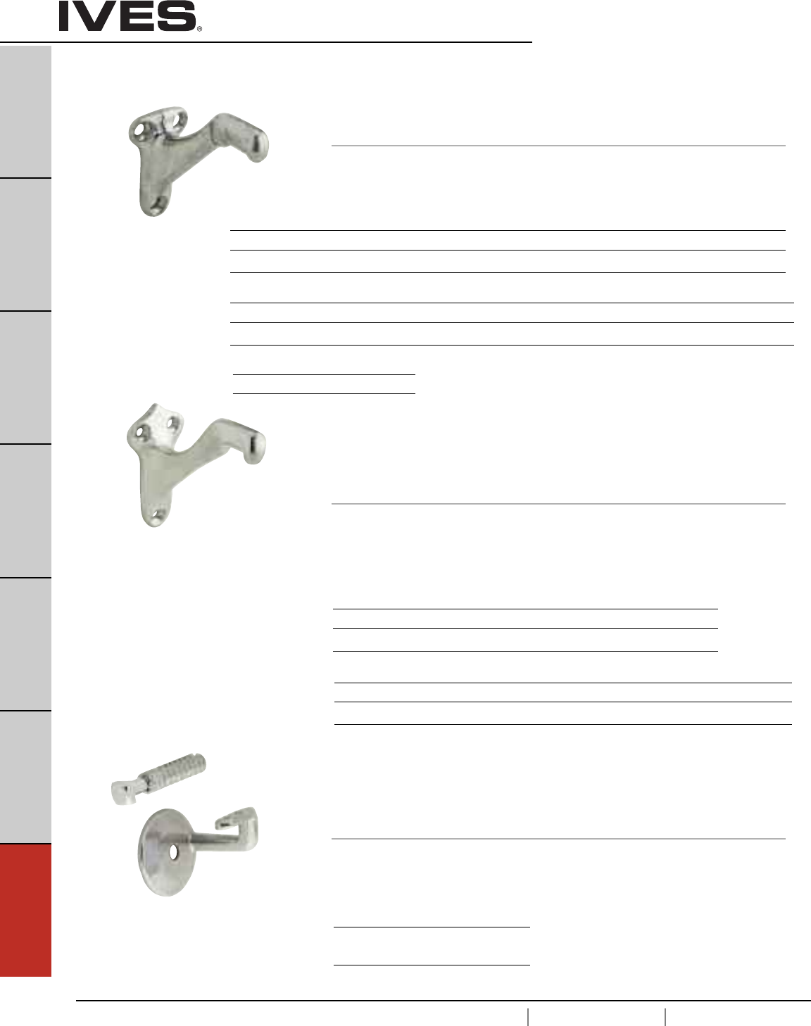
G2
USA 1.877.671.7011 Canada 1.905.403.1800 www.ives.ingersollrand.com
Hand Rail Brackets and Hooks
B
Pulls & Plates
A
Hinges & Pivots
C
Flush Bolts & Coordinators
D
Latches, Catches & Bolts
E
Stops
F
Exterior Hardware
G2
Miscellaneous Hardware
59 Hand Rail Bracket
• Made from cast brass or cast aluminum.
• Large faceplate for secure attachment to wall.
• Features solid construction for increased strength.
Dimensions
Aluminum Base: 2-13/16" High x 1-1/2" Wide
Brass Base: 2-15/16" High x 1-1/2" Wide
Base to Center of Rail: 2-3/4"
159 Hand Rail Bracket
• For use on commercial applications.
• Exceeds OSHA and BHMA strength test requirements.
• Packed with square head iron lag screw, expansion shield and screws.
• Cast Aluminum construction.
Dimensions
Base Diameter: 3-1/8"
Base to Rail Center: 3-1/8"
Meets ANSI/BHMA A156.16 L13061
for brass and L33061 for aluminum
Meets ANSI/BHMA A156.16, L33081
Meets ANSI/BHMA A156.16 L13061
for brass and L33061 for aluminum
Finishes brass
Ives Number B3 B5 B15 B26 B26D B716
BHMA 605 609 619 625 626
Finishes aluminum
Ives Number A3 A5 A10B A14 A15 A92 A716
BHMA 666 703 669 670 673
Finishes aluminum
Ives Number A3 A92
BHMA 666 673
059 Hand Rail Bracket
• Made from solid brass, cast aluminum or epoxy-coated aluminum.
• Large faceplate for secure attachment to wall.
• Features solid construction for increased strength.
Dimensions
Base: 2-1/4" High x 1-3/8" Wide
Base to Center of Rail: 2-7/16"
Finishes brass
Ives Number B3 B5 B10B B15 B15A B19 B26 B26D B716
BHMA 605 609 613 619 620 622 625 626
Finishes aluminum
Ives Number A3 A5 A10 A10B A14 A15 A92 A716 A-BLK A-W
BHMA 666 668 703 669 670 673
Finishes zinc
Ives Number Z619E
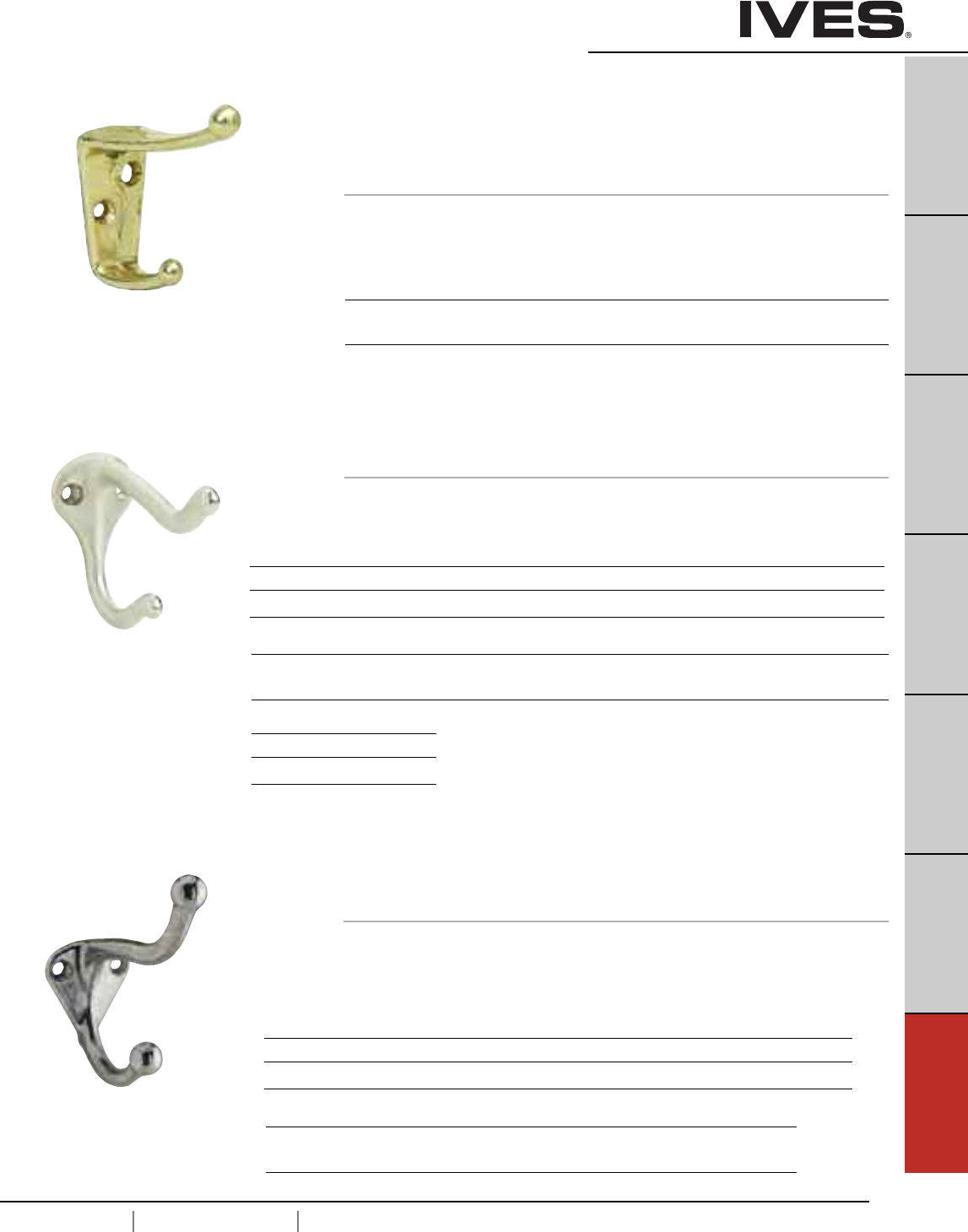
G3
USA 1.877.671.7011 Canada 1.905.403.1800 www.ives.ingersollrand.com
Hooks
B
Pulls & Plates
A
Hinges & Pivots
C
Flush Bolts & Coordinators
D
Latches, Catches & Bolts
E
Stops
F
Exterior Hardware
G3
Miscellaneous Hardware
572 Coat & Hat Hook
• Step-up decorative version of the traditional all-purpose hook.
• Ideal for locations where additional strength is required.
• Made from cast brass or cast aluminum.
Dimensions
Brass Base: 1-1/2" High x 1-5/16" Wide
Aluminum Base: 1-5/8" High x 1-5/16" Wide
Projection: 3"
405 Coat & Hat Hook
• Wide body design is ideal for public buildings, schools, dormitories,
etc., where hook must withstand unusual stress and strain.
• Made from cast aluminum.
Dimensions
Base: 1-1/2" High x 7/8" Wide
Projection: 2-1/2"
Meets ANSI/BHMA A156.16 L33113
Finishes brass
Ives Number B3 B4 B5 B10 B10B B15 B26 B26D
BHMA 605 606 609 612 613 619 625 626
Finishes aluminum
Ives Number A3 A5 A10 A10B A14 A15 A92
BHMA 666 668 703 669 670 673
Finishes aluminum
Ives Number A3 A4 A5 A10 A10B A14 A92
BHMA 666 667 668 703 669 673
571 Coat & Hat Hook
• All-purpose hook in traditional design.
• Made from cast brass, cast aluminum, or epoxy-coated aluminum.
Dimensions
Base: 1-3/4" High x 1-1/4" Wide
Projection: 3"
Meets ANSI/BHMA A156.16 L13113
for brass and L33113 for aluminum.
Finishes brass
Ives Number B3 B4 B5 B10B B15 B15A* B26 B26D B716
BHMA 605 606 609 613 619 620 625 626
Finishes aluminum
Ives Number A3 A5 A10 A14 A15 A92 A716 A-W A-BLK
BHMA 666 668 669 670 673
Finishes zinc
Ives Number Z619E
BHMA
* only available in Schlage Carded or Slim-Pak of 25
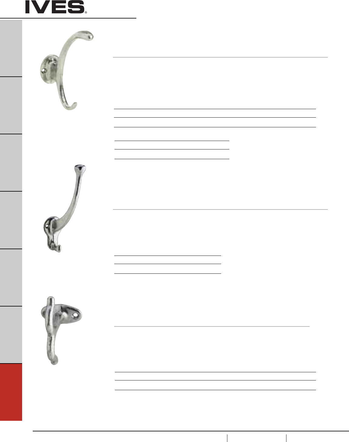
G4
USA 1.877.671.7011 Canada 1.905.403.1800 www.ives.ingersollrand.com
Hooks
B
Pulls & Plates
A
Hinges & Pivots
C
Flush Bolts & Coordinators
D
Latches, Catches & Bolts
E
Stops
F
Exterior Hardware
G4
Miscellaneous Hardware
574 Coat & Hat Hook
• Decorative design is ideal for commercial and residential installations.
• Made from cast brass, cast aluminum or epoxy-coated aluminum.
Dimensions
Base: 1-5/8" High x 1-3/4" Wide
Projection: 3-3/4"
Overall Height, Brass: 4-3/4"
Overall Height, Aluminum: 5"
575 Coat & Hat Hook
• Especially designed to accommodate large hats.
• Made from solid brass or cast aluminum.
Dimensions
Base: 2-1/4" High x 1-3/8" Wide
Projection: 3-5/8"
Overall Height: 5-3/4"
Meets ANSI/BHMA A156.16 L13113 for
brass and L33113 for aluminum
Meets ANSI/BHMA A156.16 L33121
Finishes brass
Ives Number B3 B4 B10 B10B B15 B26 B26D
BHMA 605 606 612 613 619 625 626
Finishes aluminum
Ives Number A3 A26 A92
BHMA 666 672 673
Finishes aluminum
Ives Number A3 A10B A92
BHMA 666 703 673
580 Ceiling Hook
• Ideal for use in closets, attached to underside of shelves,
or in storage lockers.
• Made from cast brass or cast aluminum.
Dimensions
Base: 1" High x 1-7/8" Wide
Projection: 2-1/4"
Finishes
Ives Number A3 A5 A10 A14 A15 A92 A716
BHMA 666 668 669 670 673
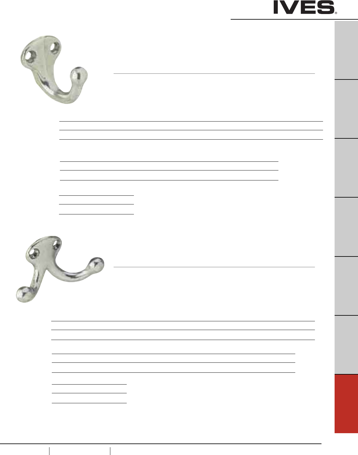
G5
USA 1.877.671.7011 Canada 1.905.403.1800 www.ives.ingersollrand.com
Hooks
B
Pulls & Plates
A
Hinges & Pivots
C
Flush Bolts & Coordinators
D
Latches, Catches & Bolts
E
Stops
F
Exterior Hardware
G5
Miscellaneous Hardware
581 Wardrobe Hook
• Compact hook is perfect where space is limited,
such as behind doors where low profile is needed.
• Made from cast brass, cast aluminum or epoxy-coated aluminum.
Dimensions
Base, Brass/Aluminum: 1-1/4" High x 1-1/4" Wide
Base, Zinc: 1-1/2" High x 3/4" Wide
Projection, Brass: 1-11/16"
Projection, Aluminum, Zinc: 1-5/8"
582 Double Wardrobe Hook
• Compact double hook is perfect where space is limited,
such as behind doors where low profile is needed.
• Made from cast brass, cast aluminum or epoxy-coated aluminum.
Dimensions
Base, Brass: 1-1/8" High x 1-1/4" Wide
Base, Aluminum: 1-1/16" Hgh x 1-3/16 Wide
Base, Zinc: 1-5/8" High x 7/8" Wide
Projection, Brass: 1"
Projection, Aluminum, Zinc: 1-3/32"
Finishes brass
Ives Number B3 B4 B5 B10 B10B B15 B15A* B26 B26D B716
BHMA 605 606 609 612 613 619 620 625 626
* only available in Schlage Carded
Finishes aluminum
Ives Number A3 A5 A14 A15 A92 A716 A-BLK A-W
BHMA 666 669 670 673
Finishes zinc (narrow base)
Ives Number Z619E
BHMA
Finishes zinc (narrow base)
Ives Number Z619E
BHMA
Finishes brass
Ives Number B3 B4 B5 B10 B10B B15 B15A* B26 B26D B716
BHMA 605 606 609 612 613 619 620 625 626
Finishes aluminum
Ives Number A3 A5 A10 A14 A15 A92 A716 A-W A-BLK
BHMA 666 668 669 670 673
* only available in Schlage Carded or Slim-Pak of 25
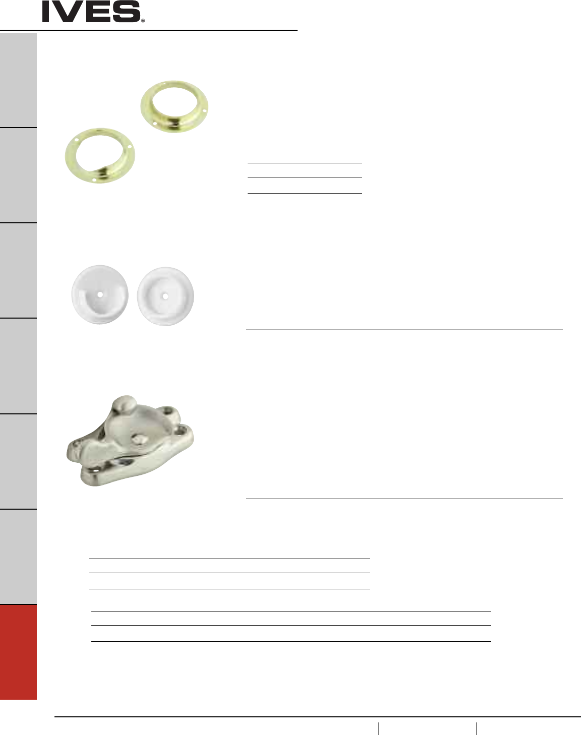
G6
USA 1.877.671.7011 Canada 1.905.403.1800 www.ives.ingersollrand.com
Window Hardware
B
Pulls & Plates
A
Hinges & Pivots
C
Flush Bolts & Coordinators
D
Latches, Catches & Bolts
E
Stops
F
Exterior Hardware
G6
Miscellaneous Hardware
SP585 Closet Pole Sockets
•Flange design prevents accidental knock out of pole.
• Made from wrought steel.
• Accommodates pole or pipe with outside diameter of 1-3/8".
• Packed in pairs.
Finishes
Ives Number F3
BHMA 632
07 Window Lock
• Designed low to the sash for superior strength and greater
resistance to breakage.
• Vertical and horizontal camming action for snug, non-rattling fit.
• Heavy gauge springs provide long-wearing action.
• Made from solid brass, aluminum, or epoxy coated aluminum.
Dimensions
Base: 15/16" x 2-9/16"
Strike: 5/8" x 2-9/16"
SP586 Closet Pole Sockets
• Made from a heavy duty plastic for long life and extra strength.
• Single screw mounting.
• Accommodates pole or pipe with outside diameter of 1-3/8".
• Packed in pairs.
Finish
White Plastic
Finishes brass
Ives Number B3 B15 B15A* B26 B26D B716
BHMA 605 619 620 625 626
Meets ANSI/BHMA A156.16
Finishes aluminum
Ives Number A3 A5* A10B A14 A15 A92 A-716 A-W A-BLK
BHMA 666 703 669 670 673
* only available in Schlage Carded or Slim-Pak of 25
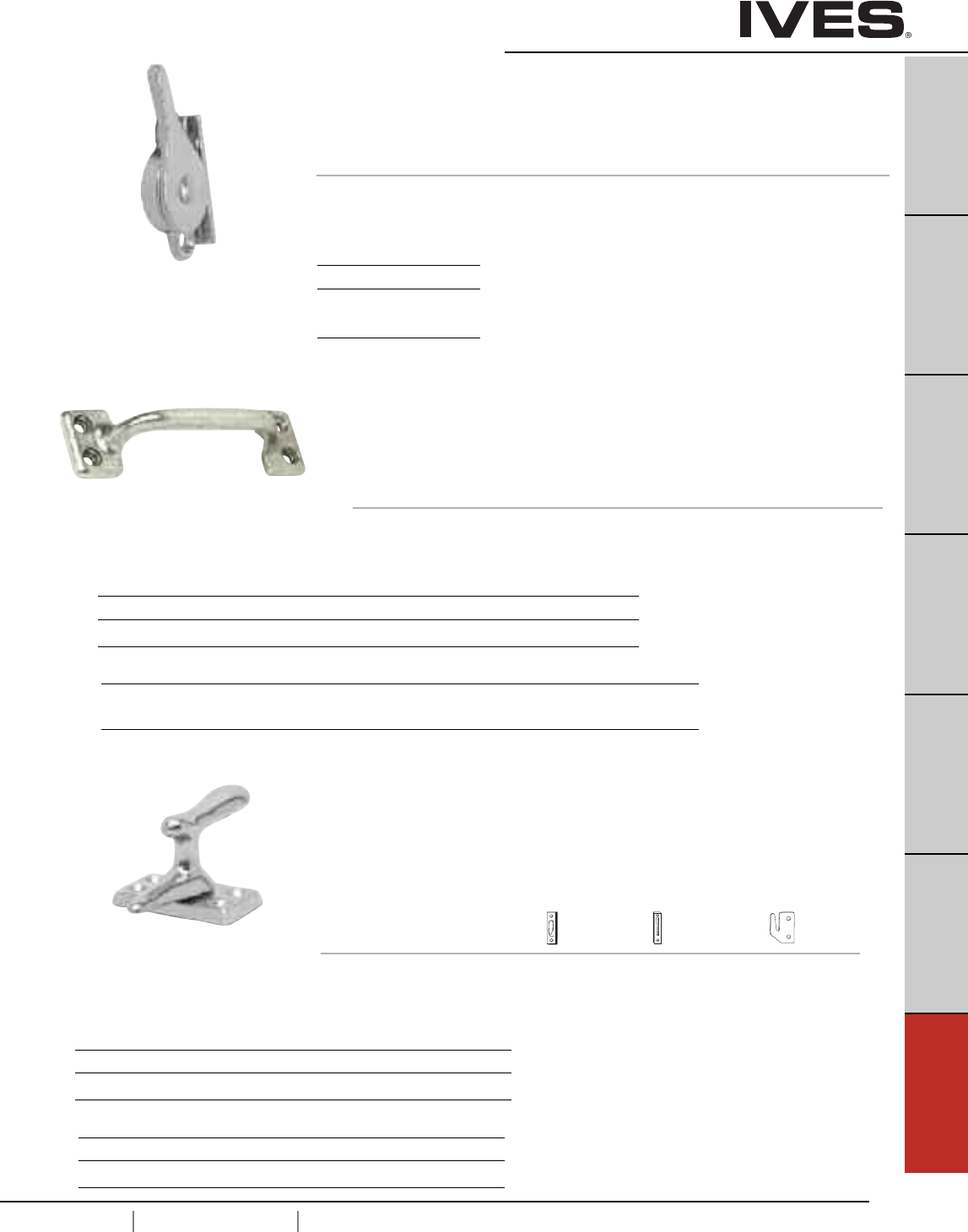
G7
USA 1.877.671.7011 Canada 1.905.403.1800 www.ives.ingersollrand.com
Window Hardare
B
Pulls & Plates
A
Hinges & Pivots
C
Flush Bolts & Coordinators
D
Latches, Catches & Bolts
E
Stops
F
Exterior Hardware
G7
Miscellaneous Hardware
90 Side Window Lock
• May be used singularly for small windows or in pairs for large windows.
• Cam action eliminates rattles and holds window firmly in desired position.
• Made from aluminum.
Dimensions
1-3/4" High x 1-1/8" Wide
Finishes
Ives Number A3
BHMA 666
Meets ANSI/BHMA A156.16
026 Bar Window Lift
• Facilitates opening of window in a safe manner.
• Can also be used as a drawer or utility pull.
• Made from solid brass, aluminum, or epoxy coated aluminum.
Dimensions
Base: 1-1/8" High x 4" Wide
Projection: 1-1/16"
Meets ANSI/BHMA A156.16
Finishes brass
Ives Number B3 B5 B15 B15A* B26 B26D B716
BHMA 605 609 619 620 625 626
Finishes aluminum
Ives Number A3 A5 A14 A15 A92 A716 A-W A-BLK
BHMA 666 669 670 673
066 Casement Fastener
• For use on windows to provide weather-tight fastening and security.
• Also ideal for securing louvered doors and small doors.
• Made from solid brass or aluminum.
• Specify: Surface , Rim , or Mortise
Strike (SS) Strike (RS) Strike (MS)
Dimensions
Base: 1-5/8" x 7/8"
Projection: 1-3/8"
Meets ANSI/BHMA A156.16
Finishes brass
Ives Number B3 B5 B15 B26 B26D
BHMA 605 609 619 625 626
Finishes aluminum
Ives Number A3 A5 A10B A14 A92
BHMA 666 668 703 673
* only available in Schlage Carded or Slim-Pak of 25
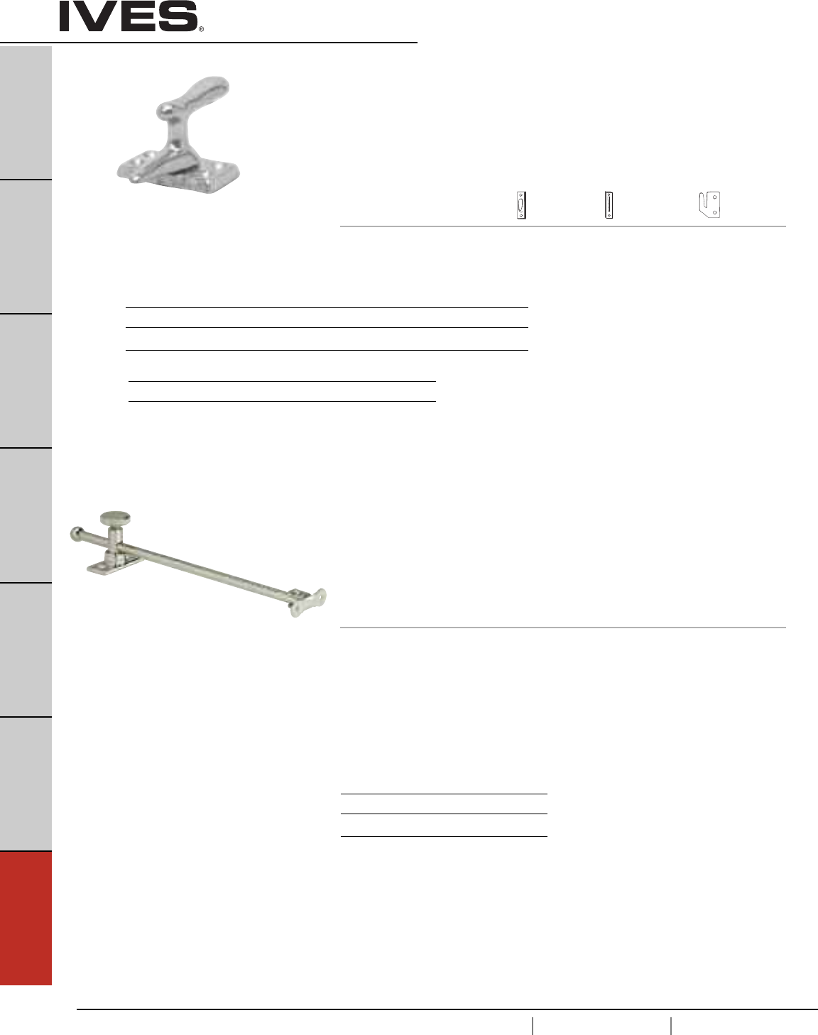
G8
USA 1.877.671.7011 Canada 1.905.403.1800 www.ives.ingersollrand.com
Window Hardware
B
Pulls & Plates
A
Hinges & Pivots
C
Flush Bolts & Coordinators
D
Latches, Catches & Bolts
E
Stops
F
Exterior Hardware
G8
Miscellaneous Hardware
66 Casement Fastener
• For use on windows to provide weather-tight fastening and security.
• Also ideal for securing louvered doors and small doors.
• Made from solid brass or aluminum.
• Specify: Surface , Rim Mortise
Strike (SS) Strike (RS) Strike (MS)
Dimensions
Base: 2-1/16" High x 1-1/16" Wide
Projection: 1-7/8"
Meets ANSI/BHMA A156.16
Finishes brass
Ives Number B3 B5 B15 B26 B26D B716
BHMA 605 609 619 625 626
Finishes aluminum
Ives Number A3 A5 A14 A92
BHMA 666 669 673
71 Casement Adjuster
• Securely holds casement window in any position.
• Can also be used to hold cabinet lids and drafting table tops in
various positions.
• Made from burnished steel or solid brass.
• Available in 10" and 12" lengths.
Dimensions
Tube: 3/8" x 5/8"
Projection: 1"
Sash Plate:
Brass: 1-5/8" High x 5/8" Wide
Steel: 2 x 5/8" Wide
Sill Plate:
2-1/4" x 15/16" Wide
Meets ANSI/BHMA A156.16
Finishes brass
Ives Number B3 B26
BHMA 605 625
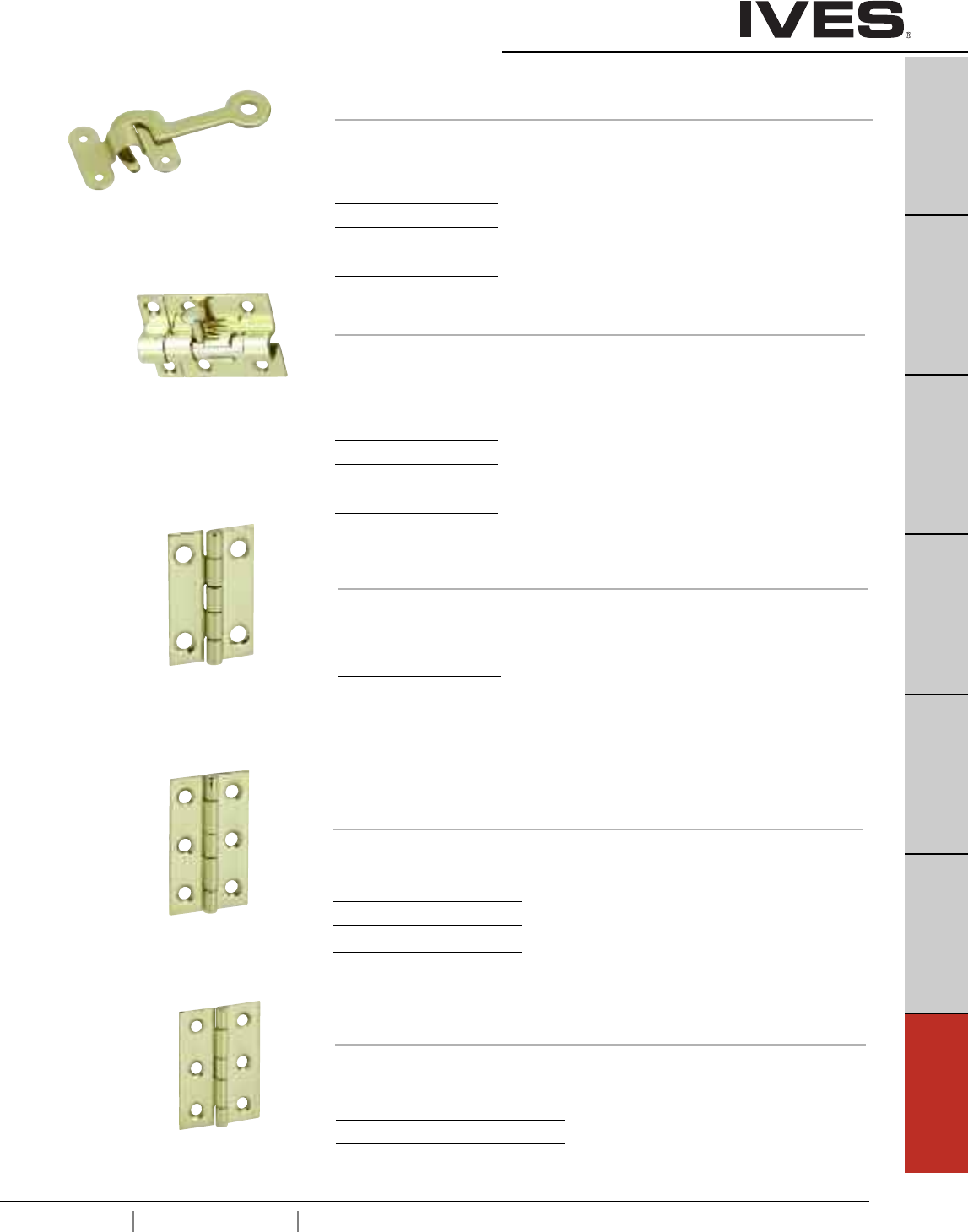
G9
USA 1.877.671.7011 Canada 1.905.403.1800 www.ives.ingersollrand.com
Hobby Hardware
B
Pulls & Plates
A
Hinges & Pivots
C
Flush Bolts & Coordinators
D
Latches, Catches & Bolts
E
Stops
F
Exterior Hardware
G9
Miscellaneous Hardware
78 Hook and Staple
• Made from solid brass.
Dimensions
Hook: 1-1/2” Long
Staple: 3/4” high x 15/16” wide
Finishes
Ives Number B3
BHMA 605
86 Hobbyist Barrel Bolt
• Made from solid brass.
Dimensions
Bolt plate: 1-9/16” high x 1-11/16” wide
Bolt guide: 1-9/16” high x 7/16” wide
Strike plate: 1-9/16” high x 5/8” wide
Finishes
Ives Number B3
BHMA 603
9011 Middle Butt Hinge
9031 Middle Butt Hinge
• Made from solid brass.
Dimensions
9011 Overall height x overall width: 3/4” x 11/16”
9031 Overall height x overall width: 1-1/2” x 1”
Finishes
Ives Number B3
BHMA 605
9042 Broad Butt Hinge
• Made from solid brass.
Dimensions
Overall height x overall width: 2” x 1-3/8”
Finishes
Ives Number B3 B5
BHMA 605 609
9041 Middle Butt Hinge
• Made from solid brass.
Dimensions
Overall height x overall width: 2” x 1-1/4”
Finishes
Ives Number B3
BHMA 605
Schlage Carded - 9011 4 per, 5 cards per box. 9031 2 per, 5 cards per box.
Schlage Carded - 2 per, 5 cards per box.
Schlage Carded - 2 per, 5 cards per box.
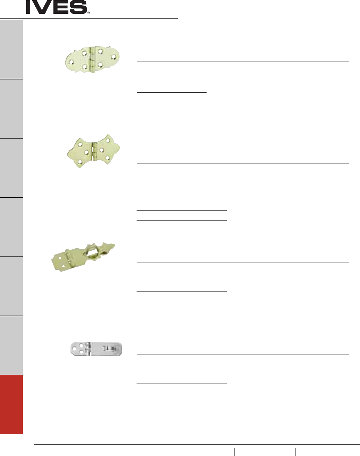
G10
USA 1.877.671.7011 Canada 1.905.403.1800 www.ives.ingersollrand.com
Hobby Hardware
B
Pulls & Plates
A
Hinges & Pivots
C
Flush Bolts & Coordinators
D
Latches, Catches & Bolts
E
Stops
F
Exterior Hardware
G10
Miscellaneous Hardware
9070 Decorative Hinge
•Made from steel.
Dimensions
Overall height x overall width: 1-5/16” x 2-7/8”
Finishes
Ives Number F3
BHMA 632
9071 Decorative Hinge
9072 Decorative Hinge
• Made from solid brass.
Dimensions
9071 Overall height x overall width: 1-3/4” x 3”
9072 Overall height x overall width: 1-5/16” x 2-1/4”
Finishes
Ives Number B3 B5
BHMA 605 609
9110 Decorative Hasp
• Made from solid brass.
Dimensions
Overall height x overall width: 5/8” x 1-7/8”
Finishes
Ives Number B3 B5
BHMA 605 609
9120 Hasp
• Made from solid brass.
Dimensions
Overall height x overall width: 3/4” x 2-3/4”
Finishes
Ives Number B3 B5
BHMA 605 609
Schlage Carded - 2 per, 5 cards per box.
Schlage Carded - 2 per, 5 cards per box.
Schlage Carded - 1 per card, 5 cards per box.
Schlage Carded - 1 per card, 5 cards per box.
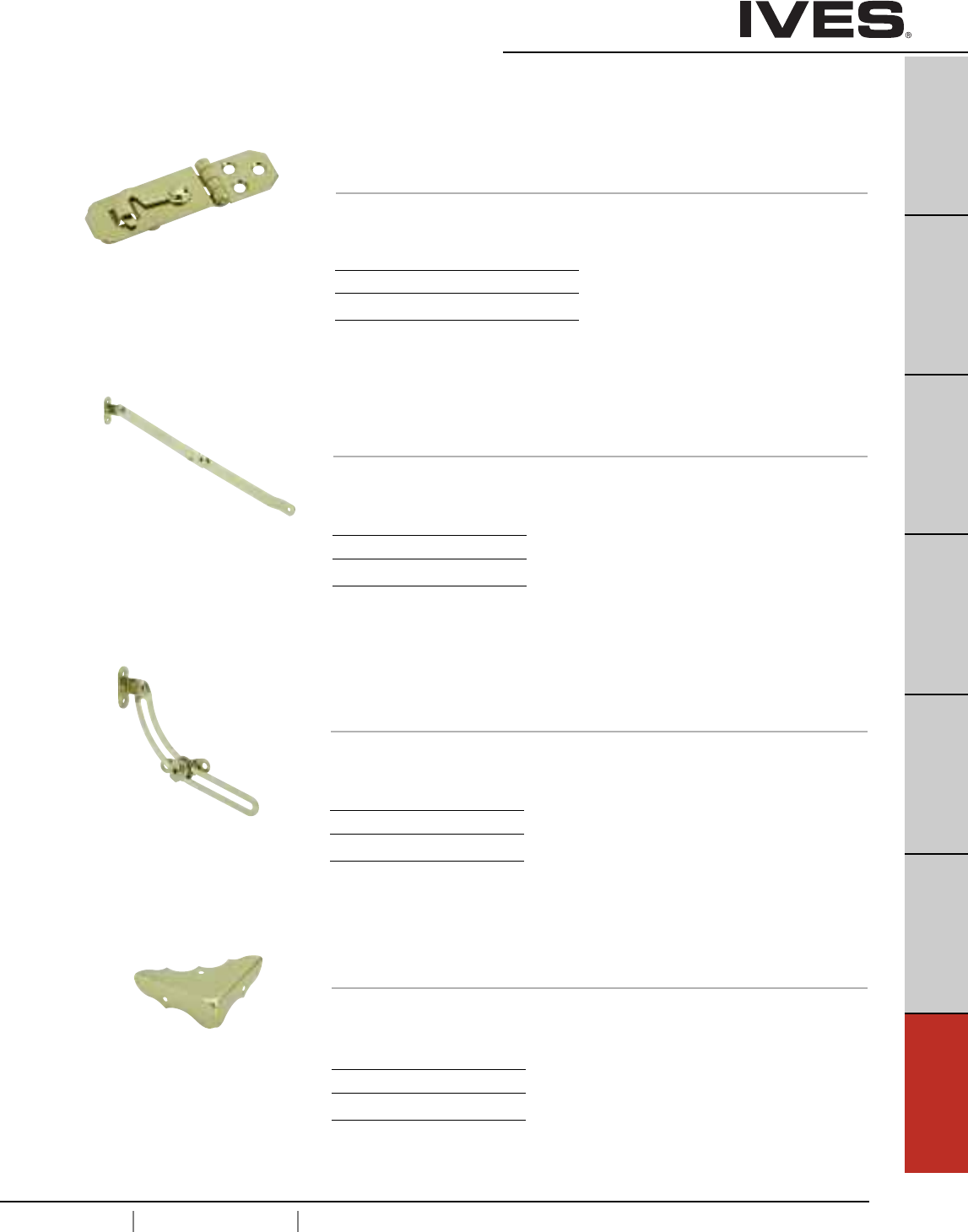
G11
USA 1.877.671.7011 Canada 1.905.403.1800 www.ives.ingersollrand.com
Hobby Hardware
B
Pulls & Plates
A
Hinges & Pivots
C
Flush Bolts & Coordinators
D
Latches, Catches & Bolts
E
Stops
F
Exterior Hardware
G11
Miscellaneous Hardware
9130 Hook with Hasp
• Made from solid brass.
Dimensions
Overall height x overall width: 3/4” x 2-3/4”
Finishes
Ives Number B3
BHMA 605
9210 Support Hinge
• Made from steel.
• Handed. Specify Left Hand (LH) or Right Hand (RH)
Dimensions
Extension: approx. 10-3/8”
Finishes
Ives Number F3
BHMA 632
9220 Friction Lid Support
• Made from steel.
• Handed. Specify Left Hand (LH) or Right Hand (RH)
Dimensions
Extension: approx. 5”
Finishes
Ives Number F3
BHMA 632
9311 Decorative Corner
• Made from solid brass.
Dimensions
9311 Side to corner: 1-3/4”
Finishes
Ives Number B3
BHMA 605
Schlage Carded - 1 per, 5 cards per box.
Schlage Carded - 1 per, 5 cards per box.
Schlage Carded - 1 per, 5 cards per box.
Schlage Carded - 4 per card, 5 cards per box.
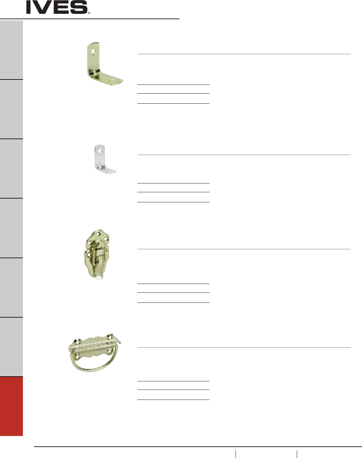
G12
USA 1.877.671.7011 Canada 1.905.403.1800 www.ives.ingersollrand.com
Hobby Hardware
B
Pulls & Plates
A
Hinges & Pivots
C
Flush Bolts & Coordinators
D
Latches, Catches & Bolts
E
Stops
F
Exterior Hardware
G12
Miscellaneous Hardware
9320 Bracket
• Made from solid brass.
Dimensions
Each leaf 1/2” x 1-1/8”
Finishes
Ives Number B3
BHMA 605
9321 Bracket
• Made from solid brass.
Dimensions
Each leaf 1/2” x 1-9/16”
Finishes
Ives Number B3
BHMA 605
9330 Draw Catch
• Made from steel.
Dimensions
Overall height: 1-1/2”
Overall width: 2-3/4”
Finishes
Ives Number F3
BHMA 632
9340 Chest Handle
• Made from steel.
Dimensions
Overall height: 1-1/2”
Overall width: 3-1/2”
Finishes
Ives Number F3
BHMA 632
Schlage Carded - 4 per, 5 cards per box.
Schlage Carded - 4 per, 5 cards per box.
Schlage Carded - 2 per, 5 cards per box.
Schlage Carded - 2 per, 5 cards per box.
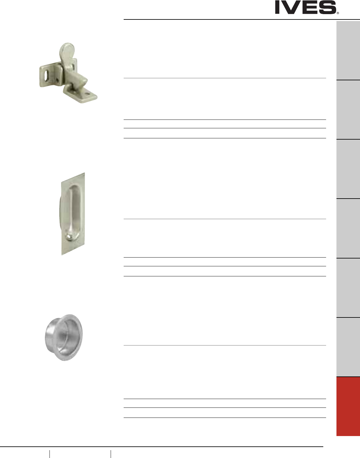
G13
USA 1.877.671.7011 Canada 1.905.403.1800 www.ives.ingersollrand.com
Cabinet/Closet Knobs and Pulls
B
Pulls & Plates
A
Hinges & Pivots
C
Flush Bolts & Coordinators
D
Latches, Catches & Bolts
E
Stops
F
Exterior Hardware
G13
Miscellaneous Hardware
2 Elbow Catch
•Ideal for use on the inactive leaf of a pair of cabinet doors.
• Surface applied, making installation simple.
• Made from cast aluminum.
Dimensions
Plate: 1-3/8" High x 5/8" Wide
Strike: 13/16" High x 5/8" Wide
22 Flush Pull
• Low profile makes this pull ideal for louvered, bi-folding or
wardrobe doors.
• Extra deep recess and reverse tapered grip provide for ease of pulling
and gripping.
• Made from wrought brass.
Dimensions
1-5/16" High x 3-1/8" Wide x 7/16" Deep
Finishes aluminum
Ives Number A3 A5 A14 A15 A92 A716
BHMA 666 669 670 673
Finishes brass
Ives Number B3 B5 B10B B15 B26 B26D
BHMA 605 609 613 619 625 626
Meets ANSI/BHMA A156.9 B33023
Meets ANSI/BHMA A156.9 B22201
and A156.14 D2781.
218 Finger Pull
• Ideal for use on sliding doors.
• Easy installation.
• Made from wrought brass.
Dimensions
Inside Cup Diameter: 3/4"
Overall Diameter: 1"
Depth: 5/16"
Finishes brass
Ives Number B3 B5 B10 B10B B15 B26 B26D
BHMA 605 609 612 613 619 625 626
Meets ANSI/BHMA A156.9 B22201
and A156.14 D2781.
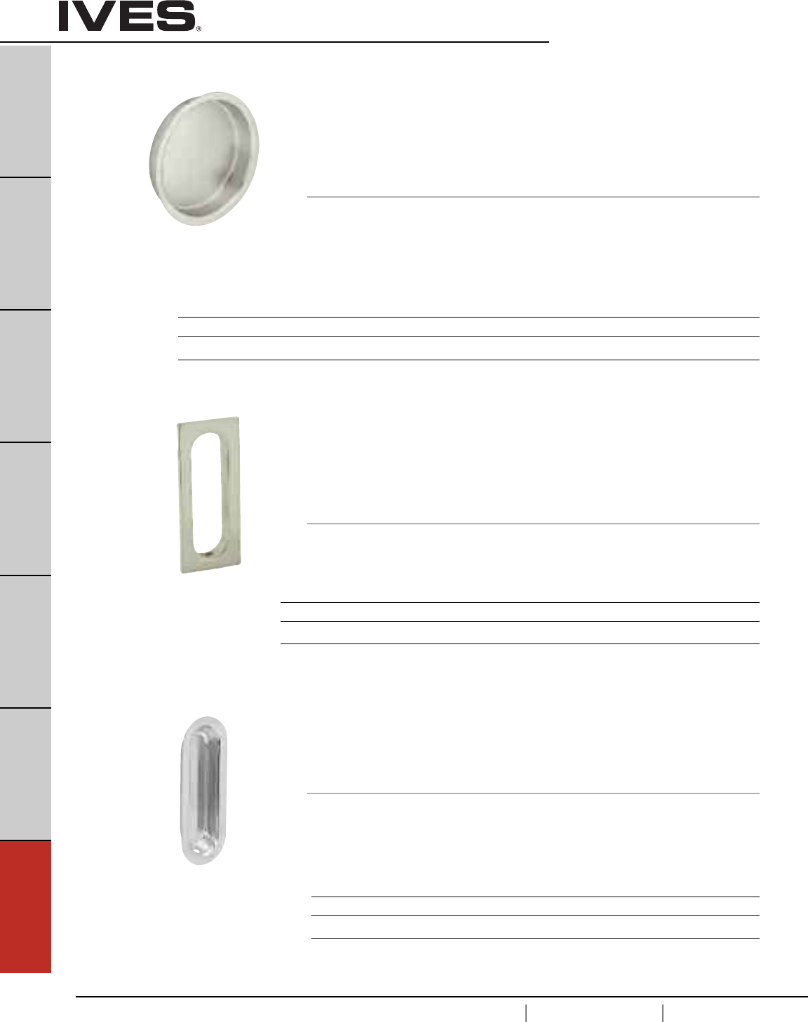
G14
USA 1.877.671.7011 Canada 1.905.403.1800 www.ives.ingersollrand.com
Cabinet/Closet Knobs and Pulls
B
Pulls & Plates
A
Hinges & Pivots
C
Flush Bolts & Coordinators
D
Latches, Catches & Bolts
E
Stops
F
Exterior Hardware
G14
Miscellaneous Hardware
222 Flush Pull
• Low profile makes this pull ideal for louvered, bi-folding or
wardrobe doors.
• Reverse tapered grip provide for ease of pulling.
• Made from cast brass.
Dimensions
3-1/8" High x 1-5/8" Wide x 7/16" Deep
Meets ANSI/BHMA A156.9 B22201
and A156.14 D2781
Meets ANSI/BHMA A156.9 B12201
and A156.14 D1781.
221 Flush Pull
• Ideal for use on sliding doors.
• Built-in prong design eliminates the need for screws or brads and
facilitates installation.
• Packed with two escutcheon pins for added holding power.
• Made from wrought brass.
Dimensions
Inside Cup Diameter: 2-1/8"
Overall Diameter: 2-7/16"
Depth: 7/16"
Finishes brass
Ives Number B3 B4 B5 B10 B10B B15 B15A* B26 B26D B716
BHMA 605 606 609 612 613 619 620 625 626
* only available in Slim-Pak of 25
Finishes brass
Ives Number B3 B4 B5 B10 B10B B15 B26 B26D
BHMA 605 606 609 612 613 619 625 626
223 Flush Pull
• Low profile makes this pull ideal for louvered, bi-folding
or wardrobe doors.
• Made from wrought brass
Dimensions
3-9/16" High x 1-5/16" Wide x 1/2" Deep
Meets ANSI/BHMA A156.9 B22201
and A156.14 D2781.
Finishes brass
Ives Number B3 B4 B10 B10B B15 B26 B26D
BHMA 605 606 612 613 619 625 626
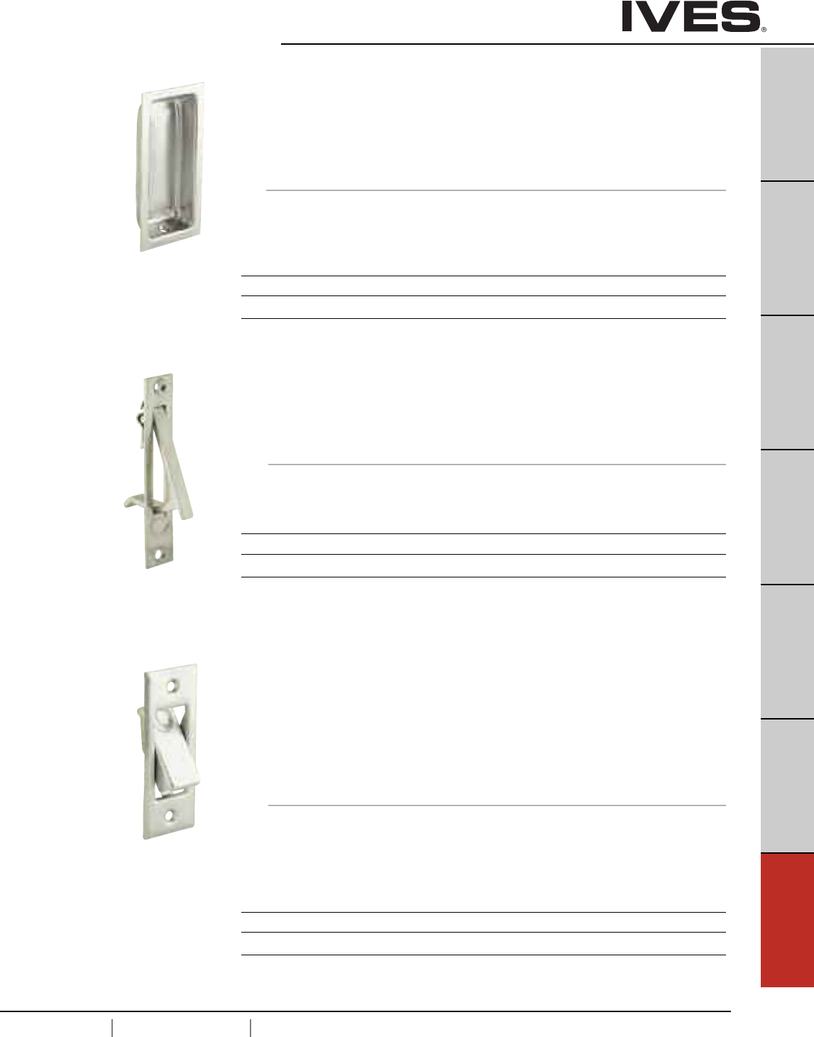
G15
USA 1.877.671.7011 Canada 1.905.403.1800 www.ives.ingersollrand.com
Cabinet/Closet Knobs and Pulls
B
Pulls & Plates
A
Hinges & Pivots
C
Flush Bolts & Coordinators
D
Latches, Catches & Bolts
E
Stops
F
Exterior Hardware
G15
Miscellaneous Hardware
230 Sliding Door Edge Pull
• 3/4" width allows installation on narrow as well as standard doors.
• Spring automatically returns lever flush with plate.
• Made from solid brass.
Dimensions
3-7/8" High x 3/4" Wide
227 Flush Pull
•Contoured for ease of pulling.
• Extra deep well.
•Deluxe quality.
• Made from wrought brass.
Dimensions
3-5/8" High x 1-3/4" Wide x 9/16" Deep
Meets ANSI/BHMA A156.9 B22201
and A156.14 D2781.
Meets ANSI/BHMA A156.14 D2801.
Finishes
Ives Number B3 B4 B5 B10 B10B B15 B26 B26D
BHMA 605 606 609 612 613 619 625 626
Finishes
Ives Number B3 B4 B5 B10 B10B B15 B26 B26D
BHMA 605 606 609 612 613 619 625 626
Finishes
Ives Number B3 B4 B5 B10 B10B B15 B26 B26D
BHMA 605 606 609 612 613 619 625 626
42 Pocket Sliding Door Bolt
•Exclusive Ives design permits emergency release of bolt from
outside the door.
• Spring activated design allows feather-touch action.
• Brass grommet supplied to cap release hole, protecting the
door’s finish.
• Made from wrought brass.
Dimensions
Overall Size Plate: 3-1/16" High x 1-5/32" Wide
Strike: 1" High x 3/4" Wide
Depth of Mortise: 5/8"
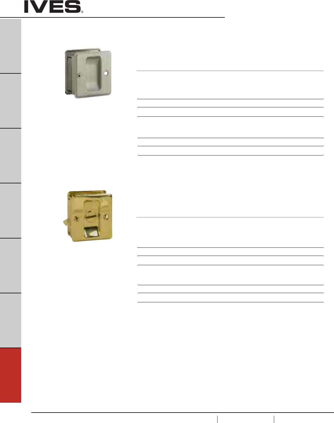
G16
USA 1.877.671.7011 Canada 1.905.403.1800 www.ives.ingersollrand.com
Cabinet/Closet Knobs and Pulls
B
Pulls & Plates
A
Hinges & Pivots
C
Flush Bolts & Coordinators
D
Latches, Catches & Bolts
E
Stops
F
Exterior Hardware
G16
Miscellaneous Hardware
991 Sliding Door Pull
• Fits doors 1-3/8" to 1-1/2".
• Decorative coined edges.
• Pre-assembled for doors opening left to right. Plates are reversible.
• Body, turn knob and strike made from solid brass.
Dimensions
1-3/4" D x 2-1/4" H
990 Sliding Door Pull
• Fits doors 1-3/8" to 1-1/2".
• Decorative coined edges.
•Pre-assembled for doors opening left to right. Plates are reversible.
• Body and strike made from solid brass.
Dimensions
1-3/4" D x 2-1/4" H
Finishes brass
Ives Number B3 B5* B10B B15 B15A* B26 B716
BHMA 605 609 613 619 620 625
* only available in Schlage Carded
Finishes aluminum
Ives Number A3 A5 A14 A15 A26D A716
BHMA 666 669 670 702
Finishes brass
Ives Number B3 B5* B10B B15 B15* B26 B716
BHMA 605 609 613 619 620 625
* only available in Schlage Carded
Finishes aluminum
Ives Number A3 A5 A14 A15 A26D A716
BHMA 666 669 670 702

© 2007 Ingersoll-Rand Company Limited MS-C62 Rev. 10/07 Printed in U.S.A.
© 2011 Ingersoll-Rand Company Limited IV-2001 Rev. 01/11 Printed in U.S.A.
Commercial Customer Service: 877.671.7011
Residential Customer Service: 800.766.1966 www.ives.ingersollrand.com
